1
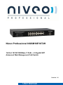
Niveo Professional NGSM16E16T2H
16-Port 10/100/1000Base-T PoE+ + 2 Gigabit SFP
Advanced Web Management PoE Switch
Version 1.0
FCC Warning
This Equipment has been tested and found to comply with the limits for a Class-A digital device,
pursuant to Part 15 of the FCC rules. These limits are designed to provide reasonable protection
against harmful interference in a residential installation. This equipment generates, uses, and can
radiate radio frequency energy. It may cause harmful interference to radio communications if the
equipment is not installed and used in accordance with the instructions. However, there is no
guarantee that interference will not occur in a particular installation. If this equipment does cause
harmful interference to radio or television reception, which can be determined by turning the equipment
off and on, the user is encouraged to try to correct the interference by one or more of the following
measures:
Reorient or relocate the receiving antenna.
Increase the separation between the equipment and receiver.
Connect the equipment into an outlet on a circuit different from that to which the receiver is
connected.
Consult the dealer or an experienced radio/TV technician for help.
CE Mark Warning
This is a Class-A product. In a domestic environment this product may cause radio interference in
which case the user may be required to take adequate measures.
NGSME16T2H User Manual | 2
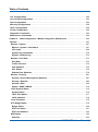
Table of Contents
Table of Contents
Before Starting ............................................................................................................................... 8
Intended Readers ......................................................................................................................... 9
Icons for Note, Caution, and Warning......................................................................................... 9
Product Package Contents .........................................................................................................10
Chapter 1:
Product Overview .................................................................................................... 11
Product Brief Description ...........................................................................................................12
Product Specification .................................................................................................................14
Hardware Description .................................................................................................................17
Hardware Installation ..................................................................................................................18
Chapter 2:
Preparing for Management ......................................................................................19
Preparation for Serial Console ...................................................................................................20
Preparation for Web Interface ....................................................................................................22
Preparation for Telnet/SSH Interface .........................................................................................24
Chapter 3:
Featuring Configuration – Web UI ..........................................................................26
System Configuration .................................................................................................................27
System Information ...................................................................................................................27
Configuration .............................................................................................................................28
IPv6 Configuration ....................................................................................................................30
NTP Configuration .....................................................................................................................32
System Log Configuration ........................................................................................................33
Power Reduction .........................................................................................................................35
LED Power Reduction Configuration .......................................................................................35
Port Configuration ......................................................................................................................38
Security Configuration: ..............................................................................................................40
Security / Switch........................................................................................................................40
Security / Switch / Users Configuration .................................................................................40
Security / Switch / Privilege Levels Configuration ................................................................42
Security / Switch / Auth Method..............................................................................................44
Security /Switch / SSH Configuration.....................................................................................45
Security / Switch / HTTPS Configuration ...............................................................................46
Security / Switch / Access Management Configuration ........................................................47
Security / Switch / SNMP .........................................................................................................49
RMON Statistics Configuration ...............................................................................................60
Security /Network ......................................................................................................................67
Port Security Limit Control Configuration .............................................................................67
NGSME16T2H User Manual | 3
Table of Contents
Security / Network / Network Access Server Configuration .................................................71
Security / Network / Access Control List Configuration .......................................................82
Switch / Network / DHCP Configuration .................................................................................99
IP Source Guard Configuration ............................................................................................102
ARP Inspection ......................................................................................................................104
Security / AAA Authentication Server Configuration ............................................................107
Aggregation Configuration ....................................................................................................... 110
Static Aggregation ................................................................................................................... 110
LACP - Dynamic Aggregation ................................................................................................. 112
Loop Protection......................................................................................................................... 114
Spanning Tree ........................................................................................................................... 116
Spanning Tree / Bridge Setting............................................................................................... 117
Spanning Tree / MSTI Mapping ............................................................................................... 119
Spanning Tree / MSTI Priorities ..............................................................................................120
Spanning Tree / CIST Ports .....................................................................................................121
Spanning Tree MSTI Ports ......................................................................................................124
MVR (Multicast VLAN Registration) .........................................................................................125
IPMC (IP Multicast) ....................................................................................................................127
IGMP Snooping Configuration................................................................................................127
Basic Configuration...............................................................................................................127
IGMP Snooping VLAN Configuration ...................................................................................130
IGMP Snooping / Port Group Filtering .................................................................................132
MLD Snooping Configuration .................................................................................................133
Basic Configuration...............................................................................................................133
MLD Snooping VLAN Configuration.....................................................................................135
IPMC / MLD Snooping / Port Group Filtering .......................................................................137
LLDP Parameters ......................................................................................................................138
LLDP Configuration.................................................................................................................138
LLDP Media Configuration......................................................................................................141
PoE Configuration.....................................................................................................................149
MAC Address Table Configuration...........................................................................................152
VLAN (Virtual LAN)....................................................................................................................155
VLAN Membership Configuration ..........................................................................................155
VLAN Port Configuration ........................................................................................................158
Private VLANs ...........................................................................................................................160
Private VLAN Membership Configuration..............................................................................160
Port Isolation Configuration ...................................................................................................162
NGSME16T2H User Manual | 4
Table of Contents
VCL.............................................................................................................................................163
VCL / MAC-Based VLAN Configuration .................................................................................163
VCL / Protocol-based VLAN ....................................................................................................165
VCL / IP Subnet-based VLAN ..................................................................................................169
Voice VLAN Configuration ........................................................................................................171
Voice VLAN / Configuration ....................................................................................................171
Voice VLAN / OUI Configuration .............................................................................................173
QoS ............................................................................................................................................174
QoS / Ingress Port Classification ...........................................................................................174
QoS / Ingress Port Policer Config ..........................................................................................176
QoS / Port Scheduler...............................................................................................................177
QoS / Egress Port Shapers .....................................................................................................178
QoS / Port Tag Remarking ......................................................................................................179
QoS / Port DSCP Configuration ..............................................................................................180
QoS / DSCP based QoS Ingress Classification .....................................................................182
QoS / DSCP Translation ..........................................................................................................183
QoS / DSCP Classification ......................................................................................................185
QoS / Control List Configuration ............................................................................................186
QoS / Storm Control Configuration ........................................................................................189
Mirroring Configuration ............................................................................................................190
UPnP Configuration ..................................................................................................................192
sFlow Configuration..................................................................................................................193
Chapter 4:
Feature Configuration - CLI ...................................................................................196
System Configuration ...............................................................................................................198
Power Reduction .......................................................................................................................205
Port Configuration ....................................................................................................................207
Security Configuration..............................................................................................................210
Aggregation Configuration .......................................................................................................230
Loop Protection.........................................................................................................................232
Spanning Tree ...........................................................................................................................233
MVR ............................................................................................................................................237
IPMC ...........................................................................................................................................239
LLDP Configuration ..................................................................................................................242
Power over Ethernet Configuration .........................................................................................244
MAC Address Table Configuration...........................................................................................246
VLAN Configuration ..................................................................................................................248
Private VLAN Configuration .....................................................................................................249
NGSME16T2H User Manual | 5
Table of Contents
VCL Configuration.....................................................................................................................250
Voice VLAN Configuration ........................................................................................................252
QoS Configuration ....................................................................................................................254
Mirroring Configuration ............................................................................................................258
UPnP Configuration ..................................................................................................................259
sFlow Configuration..................................................................................................................260
Diagnostic Commands .............................................................................................................262
Maintenance Commands ..........................................................................................................264
Chapter 5:
Web Configuration - Monitor, Diagnostic, Maintenance ......................................266
Monitor .......................................................................................................................................267
Monitor / System .....................................................................................................................267
Monitor / System / Information .............................................................................................267
CPU Load ...............................................................................................................................269
System Log Information ........................................................................................................270
System / Detailed Log............................................................................................................272
Monitor / Port State .................................................................................................................273
Port State................................................................................................................................273
Traffic Overview .....................................................................................................................274
QoS Statistics ........................................................................................................................275
QCL Status .............................................................................................................................276
Detailed Port Statistics ..........................................................................................................278
Monitor / Security ....................................................................................................................281
Security / Access Management Statistics ............................................................................281
Security / Network .................................................................................................................282
Security / AAA ........................................................................................................................302
Switch / SNMP / RMON ..........................................................................................................310
LACP System Status ...............................................................................................................316
System Status ........................................................................................................................316
LACP Port Status ...................................................................................................................317
LACP statistics ......................................................................................................................318
Loop Protection .......................................................................................................................319
STP Bridge Status ...................................................................................................................319
Bridge Status .........................................................................................................................320
STP Port Status......................................................................................................................321
STP Port Statistics .................................................................................................................322
MVR Status ..............................................................................................................................323
Statistics.................................................................................................................................323
NGSME16T2H User Manual | 6
Table of Contents
MVR Group Table ...................................................................................................................324
Monitor / IPMC / IGMP Snooping ............................................................................................325
IGMP Snooping ......................................................................................................................325
MLD Snooping Status............................................................................................................330
Monitor / LLDP .........................................................................................................................335
LLDP / Neighbor.....................................................................................................................335
LLDP MED Neighbors ............................................................................................................337
LLDP PoE ...............................................................................................................................341
LLDP EEE ...............................................................................................................................343
LLDP Statistics ......................................................................................................................345
Dynamic MAC Table ................................................................................................................347
VLAN Membership Status .......................................................................................................349
VCL MAC-Based VLAN Status ................................................................................................353
sFlow ........................................................................................................................................354
Diagnostic..................................................................................................................................355
Ping ..........................................................................................................................................355
Ping6 ........................................................................................................................................356
VeriPHY Cable Diagnostic.......................................................................................................357
Maintenance ..............................................................................................................................358
Restart Device .........................................................................................................................358
Factory Defaults ......................................................................................................................358
Software Upload ......................................................................................................................359
Firmware Update....................................................................................................................359
Image Select ..........................................................................................................................360
Configuration ...........................................................................................................................361
Appendix A: Product Safety .......................................................................................................363
Appendix B: IP Configuration for Your PC ................................................................................364
NGSME16T2H User Manual | 7
Before Starting
In Before Starting:
This section contains introductory information, which includes:
Intended Readers
Icons for Note, Caution, and Warning
Product Package Contents
NGSME16T2H User Manual | 8
Before Starting
Intended Readers
This manual provides information regarding to all the aspects and functions needed
to install, configure, use, and maintain the product you’ve purchased.
This manual is intended for technicians who are familiar with in-depth concepts of
networking management and terminologies.
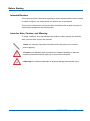
Icons for Note, Caution, and Warning
To install, configure, use, and maintain this product properly, please pay attention
when you see these icons in this manual:
A Note icon indicates important information which will guide you to use this
product properly.
A Caution icon indicates either a potential for hardware damage or data loss,
including information that will guide you to avoid these situations.
A Warning icon indicates potentials for property damage and personal injury.
NGSME16T2H User Manual | 9
Before Starting
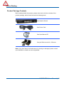
Product Package Contents
Before starting install this product, please check and verify the contents of the
product package, which should include the following items:
One Network Switch
One Power Cord
One User Manual CD
One pair Rack-mount kit + 8 Screws
Note: If any item listed in this table above is missing or damaged, please contact
your distributor or retailer as soon as possible.
NGSME16T2H User Manual | 10
Chapter 1:
Product Overview
In Product Overview:
This section will give you an overview of this product, including its feature functions
and hardware/software specifications.
Product Brief Description
Product Specification
Hardware Description
Hardware Installation
NGSME16T2H User Manual | 11
Chapter 1: Product Overview
Product Overview
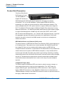
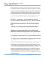
Product Brief Description
This Niveo Web Smart
PoE Switch is 16-port
10/100/1000Base-T + 2
Gigabit SFP Advanced
Web Management PoE Switch that is designed to strengthen its network
connections. The 16 10/100/1000Base-T ports support IEEE 802.3at PoE+
technology, up to 30W per port and maximum 100m transmission distance. The
switch equipped with AC to DC power module to support 200W power budget for
PoE. The added 2 SFP slots support 100M and Gigabit Fiber transceiver for long
distance transmission. The Switch embedded advanced web smart software engine
to support Web Management, SNMP, 802.1Q VLAN, QoS, RSTP, LACP, LLDP,
802.1X and Access Management…etc. The 4K VLAN, 8 physical queues, 13 groups
link aggregation groups are superb functionality for all applications. With these
features, the switch is ideal for the SMB network environment to strengthen its
network connection.
IEEE 802.3at Power over Ethernet (PoE+) ports
The switch features 16 IEEE 802.3at Power over Ethernet (PoE+) ports supplying up
to 30 watts per port. This product can convert standard 100~240V/AC power into
low-voltage DC that runs over existing LAN cable to power up IEEE 802.3at
compliant network accessories. It also features PoE awareness to verify whether the
network device receive power is IEEE 802.3at compliant, or only the data will be
sent through LAN cable. By adding the switch to the existing networking, installing
networking products such as Access Points and IP cameras can be easily managed
and set up. Wireless device deployments are easily located with available power
outlets and network administrators don’t need to use heavy AC power adapters
anymore.
2 Gigabit SFP Open Slots
The switch supports 2 additional SFP open slots to uplink to servers, storage, or
other switching devices for long loop reach applications. The 2 SFP slots can
support different types, speed and distance SFP transceivers. It also supports
legacy 100M SFP transceiver. If the 100M fiber infrastructure is constructed and
100M bandwidth is enough, the 100M SFP transceiver can be an optional choice for
the legacy 100M network environment.
NGSME16T2H User Manual | 12
Chapter 1: Product Overview
Product Overview
Advanced Web Smart Features
The switch features advanced web smart management features and SNMP for
remote management. Through a Web-based interface, an administrator can set up
VLANs to segregate traffic, QoS to prioritize mission-critical data, RSTP/Loop
Protection to avoid network loop, link aggregation to create fat traffic pipelines,
bandwidth control to limit traffic load and the 802.1X and Access Management to
secure your network. Furthermore, it provides Cable Diagnostic, Ping, Firmware
upgrading, Configuration Backup and Restore are very helpful for remote diagnostic
and maintenance.
NGSME16T2H User Manual | 13
Chapter 1: Product Overview
Product Overview
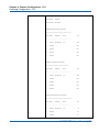
Product Specification
Standard
Ethernet : IEEE 802.3 10Base-T, IEEE 802.3u 100Base-TX, IEEE 802.ab
1000Base-T, IEEE 802.3z 1000Base-SX/LX,
IEEE 802.3x Full-duplex and Flow Control
IEEE 802.3az EEE (Energy Efficient Ethernet)
IEEE 802.3at PoE+ (Power over Ethernet)
IEEE 802.1Q VLAN
IEEE 802.3ad Link Aggregation Control Protocol
IEEE 802.1ab Link Layer Discovery Protocol
IEEE 802.1D Spanning Tree Protocol
IEEE 802.1w Rapid Spanning Tree Protocol
IEEE 802.1p Class of Service, Priority Protocols
IEEE 802.1X Port-based Network Access Control
Interface
Number of Port: 18, All Ethernet Port are on the Rear
10/100/1000Base RJ-45 Port: 16, Auto-negotiation, Auto MDI/MDIX
100/1000Base-X SFP: 2
Performance
Switch Fabric: 36Gbps
MAC Address Table Size: 8K
Forwarding Rate: 26.7Mpps
Packet Buffer: 4Mb
PoE Features
802.3af/at Compliant
Max. Power Output Per Port: 30W
PoE Power Budge: 200W
PoE Management:
Per Port: Enable/Disable, Priority Setting, Maximum Power, PoE Mode Setting
Per System: Maximum Power
PD Classification, PoE Status
L2 Features
Management Interface: Web Browser, SNMP v1/v2c/v3
IP Configuration: IP Setting, DHCP Client, NTP
NGSME16T2H User Manual | 14
Chapter 1: Product Overview
Product Overview
EEE: EEE Configuration for power reduction
Port Configuration: Auto-Negotiation, Port Speed/Duplex control, Flow Control,
Jumbo Frame Enable/Disable, Power Control
Switch Security: System Password, Access Management, HTTPS
IEEE 802.1x(NAS): Port-based access control
Link Aggregation: Static & LACP, up to 9 Groups
Spanning Tree: Rapid Spanning Tree Protocol and legacy STP
Loop Protection: Loop protection to avoid network loop
IGMP Snooping: IGMP Snooping V1/V2, IGMP Query
LLDP: IEEE 802.1ab Link Layer Discovery Protocol
MAC Address Table: Ageing Time, Static/Secure MAC Table
VLAN: IEEE 802.1Q VLAN, up to 4K groups
Private VLAN: Private VLAN and Port Isolation
QoS: 8 Priority Queue, Strict & WRR scheduler
Syslog: System log server mode
Diagnostic: Cable Diagnostic, Ping, Mirroing
Maintenance: Firmware Upgrade, Configuration Backup and Restore, Reload
Default, Warm Reboot
LEDs Indicators
Per Port PoE: On(Amber) - PD is connected
Per Port Link/Act: On/Slow Blinking(Green) – Ethernet Port is connected;
Quick Blinking(Green) – Data Transmitting/Receiving
System: On - Power On (Amber)
Power Input
100~240VAC
Power Consumption
PoE: max. 200W
System: 15W
Dimension(H*W*D)
44*330*220mm
Weight
2.2 kg
Operating Temperature
0~40℃
NGSME16T2H User Manual | 15
Chapter 1: Product Overview
Product Overview
Humidity
5~90% (non-condensing)
Certification
CE, FCC Class A
Safety: UL (UL60950-1), CE(IEC60950-1)
NGSME16T2H User Manual | 16
Chapter 1: Product Overview
Product Overview
Hardware Description
This section mainly describes the hardware of Full L2 Management Network Switch
and gives a physical and functional overview on the certain switch.
Front Panel
The front panel of the L2 management switch consists of 16 10/100/1000 Base-TX
RJ-45 ports and 2 gigabit uplink SFP ports. The LED Indicators are also located on
the front panel.
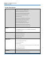
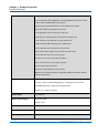
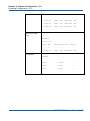
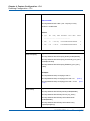
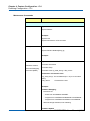
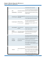
LED Indicators
The LED Indicators present real-time information of systematic operation status. The
following table provides description of LED status and their meaning.
LED
Color / Status
Description
No. of LEDs
Power
Amber On
Power on
Power
Green On
Link Up
Green Blinking
Data Activating
Amber On
PD is connected
16
Green On
linked to Power Device
17~18
Green Blinking
Data Activating
17~18
10/100/1000M
PoE
16
SFP
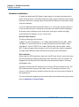
Rear Panel
The rear panel of the Web Smart PoE Switch contains 2 ventilation fans, a power
switch, and a IEC 60320 plug for power supply.
NGSME16T2H User Manual | 17
Chapter 1: Product Overview
Product Overview
Hardware Installation
To install the Web Smart PoE Switch, please place it on a large flat surface with a
power socket close by. This surface should be clean, smooth, and level. Also, please
make sure that there is enough space around the PoE Switch for RJ45 cable, power
cord and ventilation.
If you’re installing this Web Smart PoE Switch on a 19-inch rack, please make sure
to use the rack-mount kit (L brackets) and screws come with the product package.
All screws must be fastened so the rack-mount kit and your product are tightly
conjoined before installing it on your 19-inch rack.
Ethernet cable Request
The wiring cable types are as below.
10 Base-T: 2-pair UTP/STP Cat. 3, 4, 5 cable, EIA/TIA-568 100-ohm (Max. 100m)
100 Base-TX: 2-pair UTP/STP Cat. 5 cable, EIA/TIA-568 100-ohm (Max. 100m)
1000 Base-T: 4-pair UTP/STP Cat. 5 cable, EIA/TIA-568 100-ohm (Max. 100m)
PoE: To delivery power without problem, the Cat 5e and Cat 6 cable is suggested.
The high quality Ethernet cable reduces the lost while power transmission.
SFP Installation
While install the SFP transceiver, make sure the SFP type of the 2 ends is the same
and the transmission distance, wavelength, fiber cable can meet your request. It is
suggested to purchase the SFP transceiver with the switch provider to avoid any
incompatible issue.
The way to connect the SFP transceiver is to Plug in SFP fiber transceiver fist. The
SFP transceiver has 2 plug for fiber cable, one is TX (transmit), the other is RX
(receive). Cross-connect the transmit channel at each end to the receive channel at
the opposite end.
For more information regarding to the product safety and maintenance guide, please
refer to Appendix A: Product Safety.
NGSME16T2H User Manual | 18
Chapter 2:
Preparing for Management
In Preparing for Management:
This section will guide your how to manage this product via serial console,
management web page, and Telnet/SSH interface.
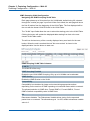
The switch provides both in-band and out-band configuration methods.
Out-band Management: You can configure the switch via RS232 console cable if
you don’t attach your admin PC to your network, or if you lose network connection to
your switch. It wouldn’t be affected by network performance. This is so-called
out-band management.
In-Band Management: You can remotely manage the switch via the Web browser,
such as Microsoft Internet Explorer, or Mozilla, to configure and interrogate the
switch from anywhere on the network.
Preparation for Serial Console
Preparation for Web Interface
Preparation for Telnet/SSH Interface
NGSME16T2H User Manual | 19
Chapter 2: Preparing for Management
Preparing for Management
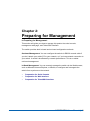
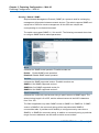
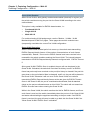
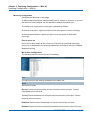
Preparation for Serial Console
In the package, there is one RS-232 console cable. Please attach one end of the
console cable to your PC COM port, the other end to the console port of the switch.
1.
Go to Start -> Program -> Accessories -> Communication -> Hyper Terminal
2.
Give a name to the new console connection.
3.
Choose the COM name
4.
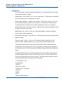
Select correct serial settings. The serial settings of the switch are as below:
Baud Rate: 115200 / Parity: None / Data Bit: 8 / Stop Bit: 1
5.
After connected, you can see Switch login request.
6.
Login the switch. The default username is “admin”, password, “admin”.
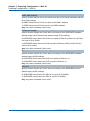
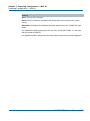
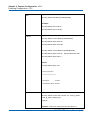
Figure 3-1 Hyper Terminal Console Screen
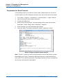
Note: The Win 7 or later OS version doesn't provide Console Terminal tool, please
download the tool, Hyper Terminal from Microsoft web site or other terminal tools,
such as PuTTY for console connection. Type Hyper Terminal or Putty in Google web
site, thus you can find link to download it.
NGSME16T2H User Manual | 20
Chapter 2: Preparing for Management
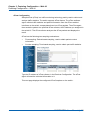
Preparing for Management
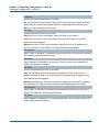
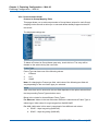
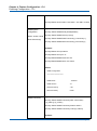
Figure 3-2 Putty Configuration
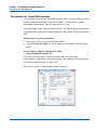
Figure 3-3 Putty Login Screen
NGSME16T2H User Manual | 21
Chapter 2: Preparing for Management
Preparing for Management
Preparation for Web Interface
The web management page allows you to use a standard web-browser such as
Microsoft Internet Explorer, Google Chrome or Mozilla Firefox, to configure and
interrogate the switch from anywhere on the network.
Before you attempt to use the web user interface to manage switch operation, verify
that your Switch is properly installed on your network and that every PC on this
network can access the switch via the web browser.
1.
Verify that your network interface card (NIC) is operational, and that your
operating system supports TCP/IP protocol.
2.
Wire the switch power and connect your computer to the switch.
3.
The switch default IP address is 192.168.2.1. The Switch and the connected
PC should locate within the same IP Subnet.
4.
Change your computer's IP address to 192.168.2.XX or other IP address which
is located in the 192.168.2.x (For example: IP Address: 192.168.2.30; Subnet
Mask: 255.255.255.0) subnet.
NGSME16T2H User Manual | 22
Chapter 2: Preparing for Management
Preparing for Management
5.
Launch the web browser and Login.
6.
Launch the web browser (Internet Explorer or Mozila Firefox) on the PC.
7.
Type http://192.168.2.1 (or the IP address of the switch). And then press Enter.
8.
The login screen will appear next.
9.
Key in the password. Default user name and password are both admin.
If you can't login the switch, the following steps can help you to identify the problem.
1. Switch to DOS command mode and type the "ipconfig" to check the NIC's setting.
Type the "ping 192.168.2.1" to verify a normal response time.
2. Check the security & firewall settings of your computer.
3. Try different Web-browser, like the Mozilla.
For more information, please refer to Appendix B: IP Configuration for Your PC.
NGSME16T2H User Manual | 23
Chapter 2: Preparing for Management
Preparing for Management
Preparation for Telnet/SSH Interface
If your Window OS is Win XP, Win 2000 or early version, you can access the Telnet
console by default command. If your OS is Window 7 or later version, please
download the terminal tool, such as HyperTeminal or Putty.
The switch support both Telnet and SSH console. The SSH console can be treated
as secured Telnet connection, need to enable the SSH feature in "Security / Switch /
SSH".
Tradition way for Telnet Connection
1. Go to Start -> Run -> cmd. And then press Enter
2. Type the Telnet 192.168.2.1 (or the IP address of the switch). And then press
Enter.
Access Telnet or SSH by Terminal tool, Putty.
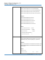
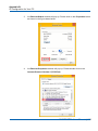
1. Open Telnet/SSH Client/PuTTY
In the Session configuration, choose the Telnet/SSH in Protocol field.
In the Session configuration, enter the Host Name (IP Address of your switch) and
Port number (default Telnet =23, SSH = 22).
Then click on “Open” to start the SSH session console.
NGSME16T2H User Manual | 24
Chapter 2: Preparing for Management
Preparing for Management
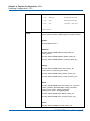
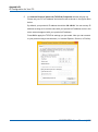
2. After click on Open, then you can see the cipher information in the popup screen.
Press Yes to accept the Security Alert.
If you choose Telnet connection, there is no such cipher information and window.
It goes to next step directly.
3. After few seconds, the Telnet/SSH connection is established, the login page of
Telnet/SSH is the same as console. The command line of Telnet, SSH and
console are all the same.
NGSME16T2H User Manual | 25
Chapter 3:
Featuring Configuration – Web
UI
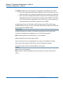
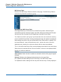
In Featuring Configuration – Web UI:
The switch provides abundant software features, after login the switch, you can start
configuring the settings or monitoring the status. This is one question market on the
right top of the screen, you can also click the question mark to get help from the
system.
NGSME16T2H User Manual | 26
Chapter 3: Featuring Configuration – Web UI
Featuring Configuration – Web UI
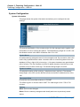
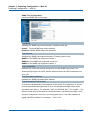
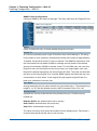
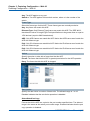
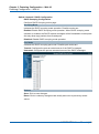
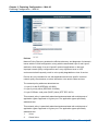
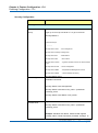
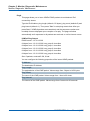
System Configuration
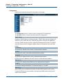
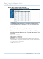
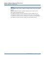
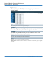
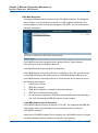
System Information
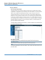
This page shows the system information and allows you to configure the new
settings.
System Contact
The textual identification of the contact person for this managed node, together with
information on how to contact this person. The allowed string length is 0 to 255, and
the allowed content is the ASCII characters from 32 to 126.
System Name
An administratively assigned name for this managed node. By convention, this is the
node's fully-qualified domain name. A domain name is a text string drawn from the
alphabet (A-Za-z), digits (0-9), minus sign (-). No space characters are permitted as
part of a name. The first character must be an alpha character. And the first or last
character must not be a minus sign. The allowed string length is 0 to 255.
System Location
The physical location of this node(e.g., telephone closet, 3rd floor). The allowed
string length is 0 to 255, and the allowed content is the ASCII characters from 32 to
126.
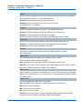
Time zone Offset
Provide the time zone offset relative to UTC/GMT.
The offset is given in minutes east of GMT. The valid range is from -720 to 720
minutes.
Buttons
Save: Click to save changes
Reset: Click to undo any changes made locally and revert to previously saved
values
NGSME16T2H User Manual | 27
Chapter 3: Featuring Configuration – Web UI
Featuring Configuration – Web UI
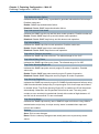
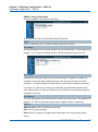
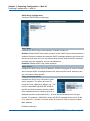
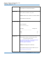
Configuration
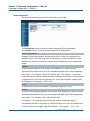
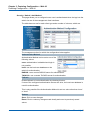
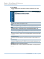
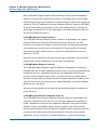
Configure the switch-managed IP information on this page.
The Configured column is used to view or change the IP configuration.
The Current column is used to show the active IP configuration.
DHCP Client
Enable the DHCP client by checking this box. If DHCP fails and the configured IP
address is zero, DHCP will retry. If DHCP fails and the configured IP address is
non-zero, DHCP will stop and the configured IP settings will be used. The DHCP
client will announce the configured System Name as hostname to provide DNS
lookup.
IP Address
Provide the IP address of this switch in dotted decimal notation.
IP Mask
Provide the IP mask of this switch dotted decimal notation.
IP Router
Provide the IP address of the router in dotted decimal notation.
NTPProvide the IP address of the NTP Server in dotted decimal notation.
DNS Server
Provide the IP address of the DNS Server in dotted decimal notation.
VLAN ID
Provide the managed VLAND ID. The allowed range is 1 to 4095.
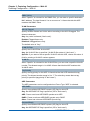
DNS Proxy
When DNS proxy is enabled, the switch will relay DNS requests to the current
configured DNS server on the switch, and reply as a DNS resolver to the client
device on the network.
NGSME16T2H User Manual | 28
Chapter 3: Featuring Configuration – Web UI
Featuring Configuration – Web UI
Buttons
Save: Click to save changes
Reset: Click to undo any changes made locally and revert to previously saved
values
Renew: Click to renew DHCP. This button is only available if DHCP is enabled.
NGSME16T2H User Manual | 29
Chapter 3: Featuring Configuration – Web UI
Featuring Configuration – Web UI
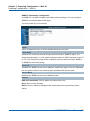
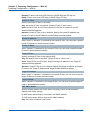
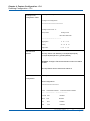
IPv6 Configuration
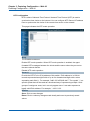
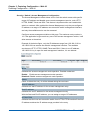
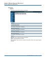
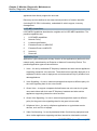
Configure the switch-managed IPv6 information on this page:
The Configured column is used to view or change the IPv6 configuration.
The Current column is used to show the active IPv6 configuration.
Auto Configuration
Enable IPv6 auto-configuration by checking this box. If fails, the configured IPv6
address is zero. The router may delay responding to a router solicitation for a few
seconds, the total time needed to complete auto-configuration can be significantly
longer.
Address
Provide the IPv6 address of this switch. IPv6 address is in 128-bit records
represented as eight fields of up to four hexadecimal digits with a colon separating
each field (:). For example, 'fe80::215:c5ff:fe03:4dc7'. The symbol '::' is a special
syntax that can be used as a shorthand way of representing multiple 16-bit groups of
contiguous zeros; but it can only appear once. It can also represent a legally valid
IPv4 address. For example, '::192.1.2.34'.
Prefix
Provide the IPv6 Prefix of this switch. The allowed range is 1 to 128.
Router
Provide the IPv6 gateway address of this switch. IPv6 address is in 128-bit records
represented as eight fields of up to four hexadecimal digits with a colon separating
each field (:). For example, 'fe80::215:c5ff:fe03:4dc7'.
The symbol '::' is a special syntax that can be used as a shorthand way of
representing multiple 16-bit groups of contiguous zeros; but it can only appear once.
It can also represent a legally valid IPv4 address. . For example, '::192.1.2.34'.
NGSME16T2H User Manual | 30
Chapter 3: Featuring Configuration – Web UI
Featuring Configuration – Web UI
Buttons
Save: Click to save changes
Reset: Click to undo any changes made locally and revert to previously saved
values
Renew: Click to renew IPv6 AUTOCONF. This button is only available if IPv6
AUTOCONF is enabled.
NGSME16T2H User Manual | 31
Chapter 3: Featuring Configuration – Web UI
Featuring Configuration – Web UI
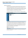
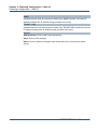
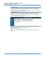
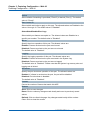
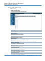
NTP Configuration
NTP is short of Network Time Protocol. Network Time Protocol (NTP) is used to
synchronize time clocks on the internet. You can configure NTP Servers' IP address
here to synchronize the clocks of the remote time server on the network.
This page indicates the NTP mode operation:
Mode
The Possible modes are:
Enable NTP mode operation. When NTP mode operation is enabled, the agent
forwards NTP messages between the clients and the server when they are not on
the same subnet domain.
Disable NTP mode operation.
Server #
Provide the NTP IPv4 or IPv6 address of this switch. IPv6 address is in 128-bit
records represented as eight fields of up to four hexadecimal digits with a colon
separating each field (:). For example, 'fe80::215:c5ff:fe03:4dc7'. The symbol '::' is a
special syntax that can be used as a shorthand way of representing multiple 16-bit
groups of contiguous zeros; but it can only appear once. It can also represent a
legally valid IPv4 address. For example, '::192.1.2.34'.
Buttons
Save: Click to save changes
Reset: Click to undo any changes made locally and revert to previously saved
values
NGSME16T2H User Manual | 32
Chapter 3: Featuring Configuration – Web UI
Featuring Configuration – Web UI
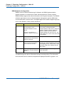
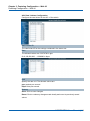
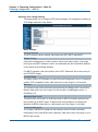
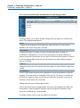
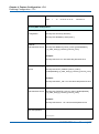
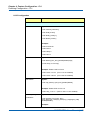
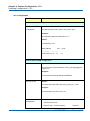
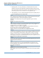
System Log Configuration
System Log is useful to provide system administrator monitor switch events history.
The switch supports syslog server mode. User can install the syslog server in one
computer, then configure the server address and event types in the switch's system
log configuration. When the events occur, the switch will send information or warning
message to the syslog server. The administrator can analysis the system logs
recorded in the syslog server to find out the cause of the issues.
The switch Web UI allows you to Enable the Syslog Server, assign the IP address
and assign the syslog level.
Server Mode
Indicates the server mode operation. When the mode operation is enabled, the
syslog message will send out to syslog server. The syslog protocol is based on UDP
communication and received on UDP port 514 and the syslog server will not send
acknowledgments back sender since UDP is a connectionless protocol and it does
not provide acknowledgments. The syslog packet will always send out even if the
syslog server does not exist. Possible modes are:
Enable server mode operation.
Disable server mode operation.
Server Address
Indicates the IPv4 host address of syslog server. If the switch provide DNS feature, it
also can be a host name.
NGSME16T2H User Manual | 33
Chapter 3: Featuring Configuration – Web UI
Featuring Configuration – Web UI
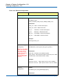
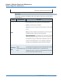
Syslog Level
Indicates what kind of message will send to
syslog server. Possible modes are:
Info: Send information, warnings and errors.
Warning: Send warnings and errors.
Error: Send errors.
Buttons
Save: Click to save changes
Reset: Click to undo any changes made locally and revert to previously saved
values
NGSME16T2H User Manual | 34
Chapter 3: Featuring Configuration – Web UI
Featuring Configuration – Web UI
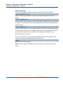
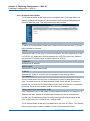
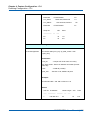
Power Reduction
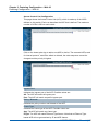
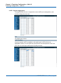
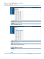
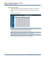
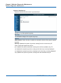
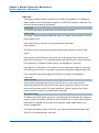
LED Power Reduction Configuration
LEDs Intensity
The LEDs power consumption can be reduced by lowering the LEDs intensity. LEDs
intensity could for example be lowered during night time, or they could be turn
completely off. It is possible to configure 24 different hours of the day, at where the
LEDs intensity should be set.
Time
The time at which the LEDs intensity shall be set. The time setting is step by one
hour.
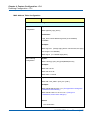
Intensity
The LEDs intensity (100% = Full power, 0% = LED off)
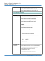
Maintenance Time
When a network administrator does
maintenance of the switch (e.g. adding or
moving users) he might want to have full
LED intensity during the maintenance
period . Therefore it is possible to specify
that the LEDs shall use full intensity a specific period of time. Maintenance Time is
the number of seconds that the LEDs will have full intensity after either a port has
changed link state, or the LED pushbutton has been pushed.
Buttons
Save: Click to save changes
Reset: Click to undo any changes made locally and revert to previously saved
values
NGSME16T2H User Manual | 35
Chapter 3: Featuring Configuration – Web UI
Featuring Configuration – Web UI
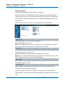
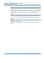
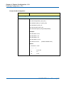
EEE Configuration:
This page allows the user to inspect and configure the current EEE port settings:
EEE is a power saving option that reduces the power usage when there is very low
traffic utilization (or no traffic).
EEE works by powering down circuits when there is no traffic. When a port gets data
to be transmitted all circuits are powered up. The time it takes to power up the
circuits is named wakeup time. The default wakeup time is 17 us for 1Gbit links and
30 us for other link speeds. EEE devices must agree upon the value of the wakeup
time in order to make sure that both the receiving and transmitting device has all
circuits powered up when traffic is transmitted. The devices can exchange
information about the devices wakeup time using the LLDP protocol.
For maximizing the power saving, the circuit isn't started at once transmit data are
ready for a port, but is instead queued until 3000 bytes of data are ready to be
transmitted. For not introducing a large delay in case that data less then 3000 bytes
shall be transmitted, data are always transmitted after 48 us, giving a maximum
latency of 48 us + the wakeup time.
If desired it is possible to minimize the latency for specific frames, by mapping the
frames to a specific queue (done with QOS), and then mark the queue as an urgent
queue. When an urgent queue gets data to be transmitted, the circuits will be
powered up at once and the latency will be reduced to the wakeup time.
NGSME16T2H User Manual | 36
Chapter 3: Featuring Configuration – Web UI
Featuring Configuration – Web UI
Port
The switch port number of the logical EEE port.
EEE Enabled
Controls whether EEE is enabled for this switch port.
EEE Urgent Queues
Queues set will activate transmision of frames as soon as any data is available.
Otherwise the queue will postpone the transmsion until 3000 bytes are ready to be
transmitted.
Buttons
Save: Click to save changes
Reset: Click to undo any changes made locally and revert to previously saved
values
NGSME16T2H User Manual | 37
Chapter 3: Featuring Configuration – Web UI
Featuring Configuration – Web UI
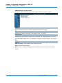
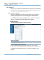
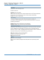
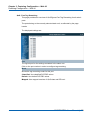
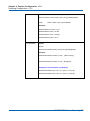
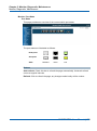
Port Configuration
This page displays current port configurations and link status. Some of the Ports'
settings can also be configured here.
Port
This is the port number for this row.
Link
The current link state is displayed graphically.
Green indicates the link is up and red that it is down.
Current Link Speed
Provides the current link speed of the port.
Ex: 1Gfdx: 1G indicates the Gigabit Speed, fdx indicates the Full Duplex Mode.
Configured Link Speed
Select any available link speed for the given switch port.
Auto Speed: selects the highest speed that is compatible with a link partner.
Disabled:
disables the switch port operation.
Fiber Speed
Configure speed for fiber port.
Note: Port speed for the Copper ports will automatically be set to Auto when dual media is
selected.
Disable SFPs (Copper port only).
SFP-Auto automatically determines the speed at the SFP.
Note: There is no standardized way to do SFP auto detect, so here it is done by reading the SFP
rom. Due to the missing standardized way of doing SFP auto detect some SFPs might not be
detectable.
1000-X force SFP speed to 1000-X.
100-FX force SFP speed to 100-FX.
NGSME16T2H User Manual | 38
Chapter 3: Featuring Configuration – Web UI
Featuring Configuration – Web UI
Flow Control
When Auto Speed is selected on a port, this section indicates the flow control
capability that is advertised to the link partner.
When a fixed-speed setting is selected, that is what is used. The Current Rx column
indicates whether pause frames on the port are obeyed, and the Current Tx column
indicates whether pause frames on the port are transmitted. The Rx and Tx settings
are determined by the result of the last Auto-Negotiation.
Check the configured column to use flow control. This setting is related to the setting
for Configured Link Speed.
Maximum Frame Size
Enter the maximum frame size allowed for the switch port, including FCS.
The switch supports up to 9K Jumbo Frame.
Excessive Collision Mode
Configure port transmit collision behavior.
Discard: Discard frame after 16 collisions (default).
Restart: Restart backoff algorithm after 16 collisions.
Power Control
The Usage column shows the current percentage of the power consumption per port.
The Configured column allows for changing the power savings mode parameters per
port.
Disabled: All power savings mechanisms disabled.
ActiPHY: Link down power savings enabled.
PerfectReach: Link up power savings enabled.
Enabled: Both link up and link down power savings enabled.
Buttons
Save: Click to save changes
Reset: Click to undo any changes made locally and revert to previously saved
values
Refresh: Click to refresh the page. Any changes made locally will be undone.
NGSME16T2H User Manual | 39
Chapter 3: Featuring Configuration – Web UI
Featuring Configuration – Web UI
Security Configuration:
The Security Configuration feature includes 3 sub-titles, Switch, Network and AAA.
Security / Switch
The switch settings includes User Database, Privilege Levels, Authentication
Method, SSH, HTTPs, Access Management, SNMP and RMON setting. Following
are the topic and configuration guide.
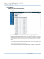
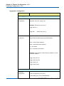
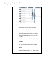
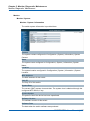
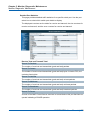
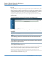
Security / Switch / Users Configuration
This page provides an overview of the current users. Currently the only way to login
as another user on the web server is to close and reopen the browser.
This page configures a user: This is also a link to Add User & Edit User
Add New User/Edit User
Click "Add New User", the
configuration page goes to "Add
User" screen. You can see the
User Setting table, follow the below
instruction to fill the table.
Click the created User Name, the page goes to "Edit User" screen, you can change
the settings on it.
User Name
A string identifying the user name that this entry should belong to. The allowed string
length is 1 to 32. The valid user name is a combination of letters, numbers and
underscores.
Password
The password of the user. The allowed string length is 0 to 32.
NGSME16T2H User Manual | 40
Chapter 3: Featuring Configuration – Web UI
Featuring Configuration – Web UI
Privilege Level
The privilege level of the user. The allowed range is 1 to 15.
If the privilege level value is 15, it can access all groups, i.e. that is granted the fully
control of the device. But others value need to refer to each group privilege level.
User's privilege should be same or greater than the group privilege level to have the
access of that group.
By default setting, most groups privilege level 5 has the read-only access and
privilege level 10 has the read-write access. And the system maintenance (software
upload, factory defaults and etc.) need user privilege level 15. Generally, the
privilege level 15 can be used for an administrator account, privilege level 10 for a
standard user account and privilege level 5 for a guest account.
Check the next chapter to see how to configure privilege level.
Buttons
Add new user: Click to add a new user.
NGSME16T2H User Manual | 41
Chapter 3: Featuring Configuration – Web UI
Featuring Configuration – Web UI
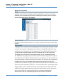
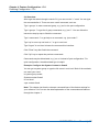
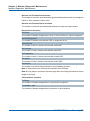
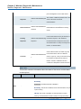
Security / Switch / Privilege Levels Configuration
This page provides an overview of the privilege levels.
Group Name
The name identifying the privilege group. In most cases, a privilege level group
consists of a single module (e.g. LACP, RSTP or QoS), but a few of them contains
more than one.
The following description defines these privilege level groups in details:
System: Contact, Name, Location, Timezone, Log.
Security: Authentication, System Access Management, Port (contains Dot1x port,
MAC based and the MAC Address Limit), ACL, HTTPS, SSH, ARP Inspection and IP
source guard.
IP: Everything except 'ping'.
Port: Everything except 'VeriPHY'.
Diagnostics: 'ping' and 'VeriPHY'.
Maintenance: CLI- System Reboot, System Restore Default, System Password,
Configuration Save, Configuration Load and Firmware Load. Web- Users, Privilege
Levels and everything in Maintenance.
Debug: Only present in CLI.
NGSME16T2H User Manual | 42
Chapter 3: Featuring Configuration – Web UI
Featuring Configuration – Web UI
Privilege Levels
Every group has an authorization Privilege level for the following sub groups:
configuration read-only, configuration/execute read-write, status/statistics read-only,
status/statistics read-write (e.g. for clearing of statistics).
User Privilege should be same or greater than the authorization Privilege level to
have the access to that group.
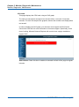
Insufficient Privilege Level: If you login with lower level privilege and try to access
the high privilege level configuration feature, the following message, Insufficient
Privilege Level will appear. If you want continue, be sure that you have the privilege.
Buttons
Save: Click to save changes
Reset: Click to undo any changes made locally and revert to previously saved
values
NGSME16T2H User Manual | 43
Chapter 3: Featuring Configuration – Web UI
Featuring Configuration – Web UI
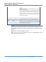
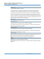
Security / Switch / Auth Method
This page allows you to configure how a user is authenticated when he logs into the
switch via one of the management client interfaces.
The table has one row for each client type and a number of columns, which are:
Client
The management client for which the configuration below applies.
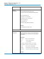
Authentication Method
Authentication Method can be set to one of the
following values:
none: authentication is disabled and login is
not possible.
local: use the local user database on the
switch for authentication.
RADIUS: use a remote RADIUS server for authentication.
TACACS+: use a remote TACACS server for authentication.
Fallback
Enable fallback to local authentication by checking this box.
If none of the configured authentication servers are alive, the local user database is
used for authentication.
This is only possible if the Authentication Method is set to a value other than 'none'
or 'local'.
Buttons
Save: Click to save changes
Reset: Click to undo any changes made locally and revert to previously saved
values
NGSME16T2H User Manual | 44
Chapter 3: Featuring Configuration – Web UI
Featuring Configuration – Web UI
Security /Switch / SSH Configuration
With SSH, you can remotely connect to the switch by command line interface. The
SSH connection can secure all the configuration commands you sent to the switch.
It is also known as secured Telnet console.
To access the switch by SSH, you should install SSH client on you computer, such
as PuTTy console tool. In the switch side, the switch acts as SSH server for user
login, and you can Enable or Disable SSH on this page.
Please check the chapter Preparation for Telnet/SSH to see how to manage the
switch through SSH console.
Mode
Indicates the SSH mode operation. Possible modes are:
Enable:
Enable SSH mode operation.
Disabled: Disable SSH mode operation.
Buttons
Save: Click to save changes
Reset: Click to undo any changes made locally and revert to previously saved
values
NGSME16T2H User Manual | 45
Chapter 3: Featuring Configuration – Web UI
Featuring Configuration – Web UI
Security / Switch / HTTPS Configuration
The web management page also provides secured management HTTPS login. All
the configuration commands will be secured and will be hard for the hackers to sniff
the login password and configuration commands.
This page allows you to configure HTTPS mode.
Mode
Indicates the HTTPS mode operation. Possible modes are:
Enable: Enable HTTPS mode operation.
Disabled: Disable HTTPS mode operation.
Automatic Redirect
Indicates the HTTPS redirect mode operation. Automatically redirect web browser to
HTTPS when HTTPS mode is enabled. Possible modes are:
Enable:
Enable HTTPS redirect mode operation.
Disabled: Disable HTTPS redirect mode operation.
Buttons
Save: Click to save changes
Reset: Click to undo any changes made locally and revert to previously saved
values
NGSME16T2H User Manual | 46
Chapter 3: Featuring Configuration – Web UI
Featuring Configuration – Web UI
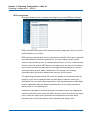
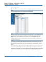
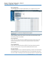
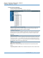
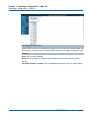
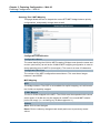
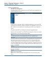
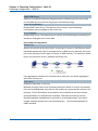
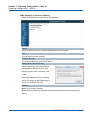
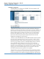
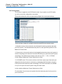
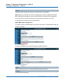
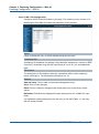
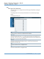
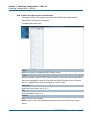
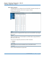
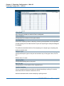
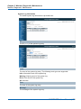
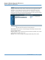
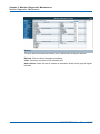
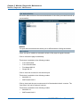
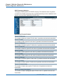
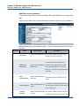
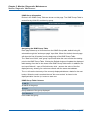
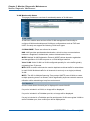
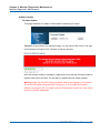
Security / Switch / Access Management Configuration
The Access Management mode allows user to limit the switch access with specific
range of IP address and disable some remote management service, such HTTP,
HTTPS, SNMP, Telnet and SSH. This feature is important while user installed the
switch on network. After enabled the Access Management, only the pre-configured
IP address or a range of IP address can access the switch management interface,
and only the available service can be accessed.
Configure access management table on this page. The maximum entry number is
16. If the application's type match any one of the access management entries, it will
allow access to the switch.
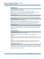
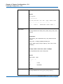
Example of the below figure, only the IP Addresses range from 192.168.2.101 to
192.168.2.200 can access the switch's management interface. The available
services are HTTP, HTTPS, SNMP, Telnet and SSH. If there is one IP address,
192.168.2.201 try to open the web management interface, it is not allowed.
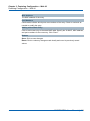
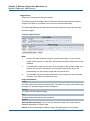
Mode
Indicates the access management mode operation. Possible modes are:
Enable:
Enable access management mode operation.
Disabled: Disable access management mode operation.
Delete
Check to delete the entry. It will be deleted during the next save.
Start IP address
Indicates the start IP address for the access management entry.
End IP address
Indicates the end IP address for the access management entry.
With the Start and End IP address, you can assign a range of IP addresses.
HTTP/HTTPS
Indicates that the host can access the switch from HTTP/HTTPS interface if the host
IP address matches the IP address range provided in the entry.
NGSME16T2H User Manual | 47
Chapter 3: Featuring Configuration – Web UI
Featuring Configuration – Web UI
SNMP
Indicates that the host can access the switch from SNMP interface if the host IP
address matches the IP address range provided in the entry.
TELNET / SSH
Indicates that the host can access the switch from TELNET/SSH interface if the host
IP address matches the IP address range provided in the entry.
Buttons
Add New Entry: Click to add a new group entry
Save: Click to save changes
Reset: Click to undo any changes made locally and revert to previously saved
values
NGSME16T2H User Manual | 48
Chapter 3: Featuring Configuration – Web UI
Featuring Configuration – Web UI
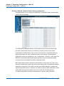
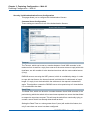
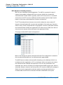
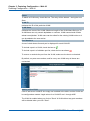
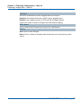
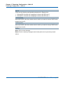
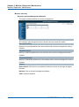
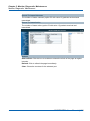
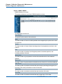
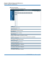
Security / Switch / SNMP
Simple Network Management Protocol (SNMP) is a protocol used for exchanging
management information between network devices. The switch supports SNMP and
equips lots of OIDs for remote management. All the OIDs are unique and
corresponding to one feature/command.
The switch can support SNMP V1, V2c and V3. The following commands show how
to configure SNMP and its related parameters.
Mode
Indicates the SNMP mode operation. Possible modes are:
Enable:
Enable SNMP mode operation.
Disabled: Disable SNMP mode operation.
Version
Indicates the SNMP supported version. Possible versions are:
SNMPv1: Set SNMP supported version 1.
SNMPv2c: Set SNMP supported version 2c.
SNMPv3: Set SNMP supported version 3.
Read Community
Indicates the community read access string to permit access to SNMP agent. The
allowed string length is 0 to 255, and the allowed content is the ASCII characters
from 33 to 126.
The field is applicable only when SNMP version is SNMPv1 or SNMPv2c. If SNMP
version is SNMPv3, the community string will be associated with SNMPv3
communities table. It provides more flexibility to configure security name than a
SNMPv1 or SNMPv2c community string. In addition to community string, a particular
range of source addresses can be used to restrict source subnet.
NGSME16T2H User Manual | 49
Chapter 3: Featuring Configuration – Web UI
Featuring Configuration – Web UI
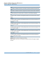
Write Community
Indicates the community write access string to permit access to SNMP agent. The
allowed string length is 0 to 255, and the allowed content is the ASCII characters
from 33 to 126.
The field is applicable only when SNMP version is SNMPv1 or SNMPv2c. If SNMP
version is SNMPv3, the community string will be associated with SNMPv3
communities table. It provides more flexibility to configure security name than a
SNMPv1 or SNMPv2c community string. In addition to community string, a particular
range of source addresses can be used to restrict source subnet.
Engine ID
Indicates the SNMPv3 engine ID. The string must contain an even number(in
hexadecimal format) with number of digits between 10 and 64, but all-zeros and
all-'F's are not allowed. Change of the Engine ID will clear all original local users.
NGSME16T2H User Manual | 50
Chapter 3: Featuring Configuration – Web UI
Featuring Configuration – Web UI
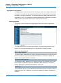
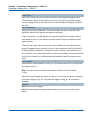
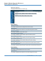
SNMP Trap Configuration
Configure SNMP trap on this page.
Trap Mode
Indicates the SNMP trap mode operation. Possible modes are:
Enable:
Enable SNMP trap mode operation.
Disabled: Disable SNMP trap mode operation.
Trap Version
Indicates the SNMP trap supported version. Possible versions are:
SNMPv1: Set SNMP trap supported version 1.
SNMPv2c: Set SNMP trap supported version 2c.
SNMPv3: Set SNMP trap supported version 3.
Trap Community
Indicates the community access string when sending SNMP trap packet. The
allowed string length is 0 to 255, and the allowed content is ASCII characters from
33 to 126.
Trap Destination Address
Indicates the SNMP trap destination address.
Trap Destination IPv6 Address
Provide the trap destination IPv6 address of this switch. IPv6 address is in 128-bit
records represented as eight fields of up to four hexadecimal digits with a colon
separating each field (:). For example, 'fe80::215:c5ff:fe03:4dc7'. The symbol '::' is a
special syntax that can be used as a shorthand way of representing multiple 16-bit
groups of contiguous zeros; but it can only appear once. It can also represent a
legally valid IPv4 address. For example, '::192.1.2.34'.
NGSME16T2H User Manual | 51
Chapter 3: Featuring Configuration – Web UI
Featuring Configuration – Web UI
Trap Authentication Failure
Indicates that the SNMP entity is permitted to generate authentication failure traps.
Possible modes are:
Enable: SNMP trap authentication failure.
Disabled: Disable SNMP trap authentication failure.
Trap Link-up and Link-down
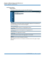
Indicates the SNMP trap link-up and link-down mode operation. Possible modes are:
Enable: Enable SNMP trap link-up and link-down mode operation.
Disabled: Disable SNMP trap link-up and link-down mode operation.
Trap Inform Mode
Indicates the SNMP trap inform mode operation. Possible modes are:
Enable: Enable SNMP trap inform mode operation.
Disabled: Disable SNMP trap inform mode operation.
Trap Inform Timeout (seconds)
Indicates the SNMP trap inform timeout. The allowed range is 0 to 2147.
Trap Inform Retry Times
Indicates the SNMP trap inform retry times. The allowed range is 0 to 255.
Trap Probe Security Engine ID
Indicates the SNMP trap probe security engine ID mode of operation. Possible
values are:
Enable: Enable SNMP trap probe security engine ID mode of operation.
Disabled: Disable SNMP trap probe security engine ID mode of operation.
Trap Security Engine ID
Indicates the SNMP trap security engine ID. SNMPv3 sends traps and informs using
USM for authentication and privacy. A unique engine ID for these traps and informs
is needed. When "Trap Probe Security Engine ID" is enabled, the ID will be probed
automatically. Otherwise, the ID specified in this field is used. The string must
contain an even number(in hexadecimal format) with number of digits between 10
and 64, but all-zeros and all-'F's are not allowed.
Trap Security Name
Indicates the SNMP trap security name. SNMPv3 traps and informs using USM for
authentication and privacy. A unique security name is needed when traps and
informs are enabled.
Buttons
Save: Click to save changes
Reset: Click to undo any changes made locally and revert to previously saved
values
NGSME16T2H User Manual | 52
Chapter 3: Featuring Configuration – Web UI
Featuring Configuration – Web UI
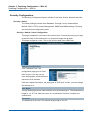
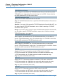
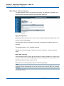
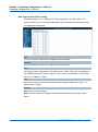
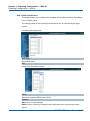
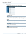
SNMPv3 Community Configuration
In SNMP V3, it is start to support User Name and its privilege. You can configure
SNMPv3 community table on this page:
The entry index key is Community.
Delete
Check to delete the entry. It will be deleted during the next save.
Community
Indicates the community access string to permit access to SNMPv3 agent. The
allowed string length is 1 to 32, and the allowed content is ASCII characters from 33
to 126. The community string will be treated as security name and map a SNMPv1
or SNMPv2c community string.
Source IP
Indicates the SNMP access source address. A particular range of source addresses
can be used to restrict source subnet when combined with source mask.
Source Mask
Indicates the SNMP access source address mask.
Buttons
Add new community: Click to add a new community entry
Save: Click to save changes
Reset: Click to undo any changes made locally and revert to previously saved
values
NGSME16T2H User Manual | 53
Chapter 3: Featuring Configuration – Web UI
Featuring Configuration – Web UI
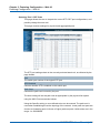
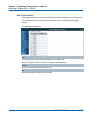
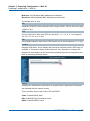
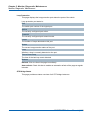
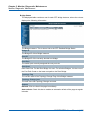
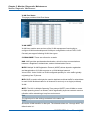
SNMPv3 User Configuration
Configure SNMPv3 user table on this page. The entry index keys are Engine ID and
User Name.
Delete
Check to delete the entry. It will be deleted during the next save.
Engine ID
An octet string identifying the engine ID that this entry should belong to. The string
must contain an even number(in hexadecimal format) with number of digits between
10 and 64, but all-zeros and all-'F's are not allowed. The SNMPv3 architecture uses
the User-based Security Model (USM) for message security and the View-based
Access Control Model (VACM) for access control. For the USM entry, the usm User
Engine ID and usm User Name are the entry's keys. In a simple agent, usm User
Engine ID is always that agent's own snmp Engine ID value. The value can also take
the value of the snmp Engine ID of a remote SNMP engine with which this user can
communicate. In other words, if user engine ID equal system engine ID then it is
local user; otherwise it's remote user.
User Name
A string identifying the user name that this entry should belong to. The allowed string
length is 1 to 32, and the allowed content is ASCII characters from 33 to 126.
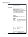
Security Level
Indicates the security model that this entry should belong to. Possible security
models are:
NoAuth, NoPriv: No authentication and no privacy.
Auth, NoPriv: Authentication and no privacy.
Auth, Priv: Authentication and privacy.
The value of security level cannot be modified if entry already exists. That means it
must first be ensured that the value is set correctly.
NGSME16T2H User Manual | 54
Chapter 3: Featuring Configuration – Web UI
Featuring Configuration – Web UI
Authentication Protocol
Indicates the authentication protocol that this entry should belong to. Possible
authentication protocols are:
None: No authentication protocol.
MD5: An optional flag to indicate that this user uses MD5 authentication protocol.
SHA: An optional flag to indicate that this user uses SHA authentication protocol.
The value of security level cannot be modified if entry already exists. That means
must first ensure that the value is set correctly.
Authentication Password
A string identifying the authentication password phrase. For MD5 authentication
protocol, the allowed string length is 8 to 32. For SHA authentication protocol, the
allowed string length is 8 to 40. The allowed content is ASCII characters from 33 to
126.
Privacy Protocol
Indicates the privacy protocol that this entry should belong to. Possible privacy
protocols are:
None: No privacy protocol.
DES: An optional flag to indicate that this user uses DES authentication protocol.
Privacy Password
A string identifying the privacy password phrase. The allowed string length is 8 to 32,
and the allowed content is ASCII characters from 33 to 126.
Buttons
Add new user: Click to add a new user entry
Save: Click to save changes
Reset: Click to undo any changes made locally and revert to previously saved
values
NGSME16T2H User Manual | 55
Chapter 3: Featuring Configuration – Web UI
Featuring Configuration – Web UI
SNMPv3 Group Configuration
Configure SNMPv3 group table on this page:
The entry index keys are Security Mode and Security Name.
Delete
Check to delete the entry. It will be deleted during the next save.
Security Model
Indicates the security model that this entry should belong to. Possible security
models are:
v1: Reserved for SNMPv1.
v2c: Reserved for SNMPv2c.
usm: User-based Security Model (USM).
Security Name
A string identifying the security name that this entry should belong to. The allowed
string length is 1 to 32, and the allowed content is ASCII characters from 33 to 126.
Group Name
A string identifying the group name that this entry should belong to. The allowed
string length is 1 to 32, and the allowed content is ASCII characters from 33 to 126.
Buttons
Add new group: Click to add a new group entry
Save: Click to save changes
Reset: Click to undo any changes made locally and revert to previously saved
values
NGSME16T2H User Manual | 56
Chapter 3: Featuring Configuration – Web UI
Featuring Configuration – Web UI
SNMPv3 View Configuration
Configure SNMPv3 view table on this page.
The entry index keys are View Name and OID Sub-tree.
Delete
Check to delete the entry. It will be deleted during the next save.
View Name
A string identifying the view name that this entry should belong to. The allowed string
length is 1 to 32, and the allowed content is ASCII characters from 33 to 126.
View Type
Indicates the view type that this entry should belong to. Possible view types are:
Included: An optional flag to indicate that this view sub-tree should be included.
excluded:
An optional flag to indicate that this view sub-tree should be excluded.
In general, if a view entry's view type is 'excluded', there should be another view
entry existing with view type as 'included' and it's OID sub-tree should overstep the
'excluded' view entry.
OID Subtree
The OID defining the root of the sub-tree to add to the named view. The allowed OID
length is 1 to 128. The allowed string content is digital number or asterisk(*).
Buttons
Add new view: Click to add a new view entry
Save: Click to save changes
Reset: Click to undo any changes made locally and revert to previously saved
values
NGSME16T2H User Manual | 57
Chapter 3: Featuring Configuration – Web UI
Featuring Configuration – Web UI
SNMPv3 Access Configuration
Configure SNMPv3 access table on this page. The entry index keys are Group
Name, Security Model, and Security Level.
Delete
Check to delete the entry. It will be deleted during the next save.
Group Name
A string identifying the group name that this entry should belong to. The allowed
string length is 1 to 32, and the allowed content is ASCII characters from 33 to 126.
Security Model
Indicates the security model that this entry should belong to. Possible security
models are:
Any: Any security model accepted(v1|v2c|usm).
V1: Reserved for SNMPv1.
V2c: Reserved for SNMPv2c.
Usm: User-based Security Model (USM).
Security Level: Indicates the security model that this entry should belong to.
Possible security models are:
NoAuth, NoPriv: No authentication and no privacy.
Auth, NoPriv: Authentication and no privacy.
Auth,Priv: Authentication and privacy.
NGSME16T2H User Manual | 58
Chapter 3: Featuring Configuration – Web UI
Featuring Configuration – Web UI
Read View Name
The name of the MIB view defining the MIB objects for which this request may
request the current values. The allowed string length is 1 to 32, and the allowed
content is ASCII characters from 33 to 126.
Write View Name
The name of the MIB view defining the MIB objects for which this request may
potentially set new values. The allowed string length is 1 to 32, and the allowed
content is ASCII characters from 33 to 126.
Buttons
Add new access: Click to add a new access entry
Save: Click to save changes
Reset: Click to undo any changes made locally and revert to previously saved
values
NGSME16T2H User Manual | 59
Chapter 3: Featuring Configuration – Web UI
Featuring Configuration – Web UI
RMON Statistics Configuration
RMON is short of Remote Monitoring On Network. An RMON implementation
typically operates in a client/server model. Monitoring device (Probe) contains
RMON software agents that collect information of the system and ports. The RMON
software agent acts as server, and the network management system (NMS) that
communicate with it acts as client. The RMON agent of the switch supports 4 groups,
such as the Statistics, History, Alarm and Event.
RMON Group
Function
Elements
Statistics
Contains statistics measured
by the probe for each
monitored interface on this
device.
Packets dropped, packets sent, bytes
sent (octets), broadcast packets,
multicast packets, CRC errors, undersize
packets, oversize packets, fragments,
jabbers, collisions, and counters for
packets ranging from 64, 65 to 127, 128
to 255, 256 to 511, 512 to 1023, and 1024
to 1518 bytes.
Real-time LAN statistics e.g.
utilization, collisions, CRC errors
History
Records periodic statistical
samples from a network and
stores for retrieval.
History of above Statistics.
Alarm
Definitions for RMON SNMP
traps to be sent when statistics
exceed defined thresholds
Interval for sampling, particular variable,
sample type, value of statistics during the
last sampling period, startup alarm, rising
threshold, rising index, falling threshold,
falling index.
Events
Controls the generation and
notification of events from this
device.
Event index, log index, event log time,
event description
The NMS can get the above information through remotely polling. The information
from the switch can be collected, analyzed and displayed as table or graphic...etc.
NGSME16T2H User Manual | 60
Chapter 3: Featuring Configuration – Web UI
Featuring Configuration – Web UI
RMON Statistics Configuration
Configure RMON Statistics table on this page. The entry index key is ID.
Delete
Check to delete the entry. It will be deleted during the next save.
ID
Indicates the index of the entry. The range is from 1 to 65535.
Data Source
Indicates the port ID which wants to be monitored. If in stacking switch, the value
must add 1000*(switch ID-1), for example, if the port is switch 3 port 5, the value is
2005
Buttons
Add new entry: Click to add a new community entry
Save: Click to save changes
Reset: Click to undo any changes made locally and revert to previously saved
values
NGSME16T2H User Manual | 61
Chapter 3: Featuring Configuration – Web UI
Featuring Configuration – Web UI
RMON History Configuration
Configure RMON History table on this page. The entry index key is ID
Delete
Check to delete the entry. It will be deleted during the next save.
ID
Indicates the index of the entry. The range is from 1 to 65535.
Data Source
Indicates the port ID which wants to be monitored. If in stacking switch, the value
must add 1000*(switch ID-1), for example, if the port is switch 3 port 5, the value is
2005.
Interval
Indicates the interval in seconds for sampling the history statistics data. The range is
from 1 to 3600, default value is 1800 seconds.
Buckets
Indicates the maximum data entries associated this History control entry stored in
RMON. The range is from 1 to 3600, default value is 50.
Buckets Granted
The number of data shall be saved in the RMON.
Buttons
Add new entry: Click to add a new community entry.
Save: Click to save changes.
Reset: Click to undo any changes made locally and revert to previously saved
values.
NGSME16T2H User Manual | 62
Chapter 3: Featuring Configuration – Web UI
Featuring Configuration – Web UI
RMON Alarm Configuration
Configure RMON Alarm table on this page. The entry index key is ID.
Delete
Check to delete the entry. It will be deleted during the next save.
ID
Indicates the index of the entry. The range is from 1 to 65535.
Interval
Indicates the interval in seconds for sampling and comparing the rising and falling
threshold. The range is from 1 to 2^31-1.
Variable
Indicates the particular variable to be sampled, the possible variables are:
InOctets:The total number of octets received on the interface, including framing
characters.
InUcastPkts:The number of uni-cast packets delivered to a higher-layer protocol.
InNUcastPkts: The number of broad-cast and multi-cast packets delivered to a
higher-layer protocol.
InDiscards: The number of inbound packets that are discarded even the packets
are normal.
InErrors: The number of inbound packets that contained errors preventing them
from being deliverable to a higher-layer protocol.
InUnknownProtos: The number of the inbound packets that were discarded
because of the unknown or un-support protocol.
OutOctets: The number of octets transmitted out of the interface , including framing
characters.
OutUcastPkts: The number of uni-cast packets that request to transmit.
NGSME16T2H User Manual | 63
Chapter 3: Featuring Configuration – Web UI
Featuring Configuration – Web UI
OutNUcastPkts: The number of broad-cast and multi-cast packets that request to
transmit.
OutDiscards: The number of outbound packets that are discarded event the
packets is normal.
OutErrors: The number of outbound packets that could not be transmitted because
of errors.
OutQlen: The length of the output packet queue (in packets).
Sample Type
The method of sampling the selected variable and calculating the value to be
compared against the thresholds, possible sample types are:
Absolute: Get the sample directly.
Delta: Calculate the difference between samples (default).
Value
The value of the statistic during the last sampling period.
Startup Alarm
The method of sampling the selected variable and calculating the value to be
compared against the thresholds, possible sample types are:
Rising Trigger alarm when the first value is larger than the rising threshold.
Falling Trigger alarm when the first value is less than the falling threshold.
RisingOrFalling Trigger alarm when the first value is larger than the rising threshold
or less than the falling threshold (default).
Rising Threshold
Rising threshold value (-2147483648-2147483647).
Rising Index
Rising event index (1-65535).
NGSME16T2H User Manual | 64
Chapter 3: Featuring Configuration – Web UI
Featuring Configuration – Web UI
Falling Threshold
Falling threshold value (-2147483648-2147483647)
Falling Index
Falling event index (1-65535).
Buttons
Add new entry: Click to add a new community entry.
Save: Click to save changes.
Reset: Click to undo any changes made locally and revert to previously saved
values.
NGSME16T2H User Manual | 65
Chapter 3: Featuring Configuration – Web UI
Featuring Configuration – Web UI
RMON Event Configuration
Configure RMON Event table on this page. The entry index key is ID.
Delete
Check to delete the entry. It will be deleted during the next save.
ID
Indicates the index of the entry. The range is from 1 to 65535.
Desc
Indicates this event, the string length is from 0 to 127, default is a null string.
Type
Indicates the notification of the event, the posible types are:
None: The total number of octets received on the interface, including framing
characters.
Log: The number of uni-cast packets delivered to a higher-layer protocol.
Snmptrap: The number of broad-cast and multi-cast packets delivered to a
higher-layer protocol.
Logandtrap: The number of inbound packets that are discarded even the packets
are normal.
Community
Specify the community when trap is sent, the string lengh is from 0 to 127, default is
"public".
Event Last Time
Indicates the value of sysUp Time at the time this event entry last generated an
event.
Buttons
Add new entry: Click to add a new community entry.
Save: Click to save changes.
Reset: Click to undo any changes made locally and revert to previously saved
values.
NGSME16T2H User Manual | 66
Chapter 3: Featuring Configuration – Web UI
Featuring Configuration – Web UI
Security /Network
Port Security Limit Control Configuration
This page allows you to configure the Port Security Limit Control system and port
settings.
Limit Control allows for limiting the number of users on a given port. A user is
identified by a MAC address and VLAN ID. If Limit Control is enabled on a port, the
limit specifies the maximum number of users on the port. If this number is exceeded,
an action is taken. The action can be one of the four different actions as described
below.
The Limit Control module utilizes a lower-layer module, Port Security module, which
manages MAC addresses learnt on the port.
The Limit Control configuration consists of two sections, a system- and a port-wide.
NGSME16T2H User Manual | 67
Chapter 3: Featuring Configuration – Web UI
Featuring Configuration – Web UI
System Configuration
Mode
Indicates if Limit Control is globally enabled or disabled on the switch. If globally
disabled, other modules may still use the underlying functionality, but limit checks
and corresponding actions are disabled.
Aging Enabled
If checked, secured MAC addresses are subject to aging as discussed under Aging
Period.
Aging Period
If Aging Period is checked, then the aging period is controlled with this input. If other
modules are using the underlying port security for securing MAC addresses, they
may have other requirements to the aging period. The underlying port security will
use the shorter requested aging period of all modules that use the functionality.
The Aging Period can be set to a number between 10 and 10,000,000 seconds.
To understand why aging may be desired, consider the following scenario: Suppose
an end-host is connected to a 3rd party switch or hub, which in turn is connected to a
port on this switch on which Limit Control is enabled. The end-host will be allowed to
forward if the limit is not exceeded. Now suppose that the end-host logs off or
powers down. If it wasn't for aging, the end-host would still take up resources on this
switch and will be allowed to forward. To overcome this situation, enable aging. With
aging enabled, a timer is started once the end-host gets secured. When the timer
expires, the switch starts looking for frames from the end-host, and if such frames
are not seen within the next Aging Period, the end-host is assumed to be
disconnected, and the corresponding resources are freed on the switch.
NGSME16T2H User Manual | 68
Chapter 3: Featuring Configuration – Web UI
Featuring Configuration – Web UI
Port Configuration
The table allows you to configure the Port Configuration parameters, which are:
Port
The port number to which the configuration below applies.
Mode
Controls whether Limit Control is enabled on this port. Both this and the Global
Mode must be set to Enabled for Limit Control to be in effect. Notice that other
modules may still use the underlying port security features without enabling Limit
Control on a given port.
Limit
The maximum number of MAC addresses that can be secured on this port. This
number cannot exceed 1024. If the limit is exceeded, the corresponding action is
taken.
The switch is "born" with a total number of MAC addresses from which all ports draw
whenever a new MAC address is seen on a Port Security-enabled port. Since all
ports draw from the same pool, it may happen that a configured maximum cannot be
granted, if the remaining ports have already used all available MAC addresses.
NGSME16T2H User Manual | 69
Chapter 3: Featuring Configuration – Web UI
Featuring Configuration – Web UI
Action
If Limit is reached, the switch can take one of the following actions:
None: Do not allow more than Limit MAC addresses on the port, but take no further
action.
Trap: If Limit+ 1 MAC addresses is seen on the port, send an SNMP trap. If Aging is
disabled, only one SNMP trap will be sent, but with Aging enabled, new SNMP traps
will be sent every time the limit gets exceeded.
Shutdown: If Limit + 1 MAC addresses is seen on the port, shut down the port. This
implies that all secured MAC addresses will be removed from the port, and no new
address will be learned. Even if the link is physically disconnected and reconnected
on the port (by disconnecting the cable), the port will remain shut down. There are
three ways to re-open the port:
1) Boot the switch,
2) Disable and re-enable Limit Control on the port or the switch,
3) Click the Reopen button.
Trap & Shutdown: If Limit + 1 MAC addresses is seen on the port, both the "Trap"
and the "Shutdown" actions described above will be taken.
State
This column shows the current state of the port as seen from the Limit Control's
point of view. The state takes one of four values:
Disabled: Limit Control is either globally disabled or disabled on the port.
Ready: The limit is not yet reached. This can be shown for all actions.
Limit Reached: Indicates that the limit is reached on this port. This state can only be
shown if Action is set to None or Trap.
Shutdown: Indicates that the port is shut down by the Limit Control module. This
state can only be shown if Action is set to Shutdown or Trap & Shutdown.
Re-open Button
If a port is shutdown by this module, you may reopen it by clicking this button, which
will only be enabled if this is the case. For other methods, refer to Shutdown in the
Action section.
Note that clicking the reopen button causes the page to be refreshed, so
non-committed changes will be lost.
Buttons
Refresh: Click to refresh the page. Note that non-committed changes will be lost.
Save: Click to save changes.
Reset: Click to undo any changes made locally and revert to previously saved
values.
NGSME16T2H User Manual | 70
Chapter 3: Featuring Configuration – Web UI
Featuring Configuration – Web UI
Security / Network / Network Access Server Configuration
This page allows you to configure the IEEE802.1X and MAC-based authentication
system and port settings.
The IEEE 802.1X standard defines a port-based access control procedure that
prevents unauthorized access to a network by requiring users to first submit
credentials for authentication. One or more central servers, the backend servers,
determine whether the user is allowed access to the network. These backend
(RADIUS) servers are configured on the "Configuration→Security→AAA" page.The
IEEE802.1X standard defines port-based operation, but non-standard variants
overcome security limitations as shall be explored below.
MAC-based authentication allows for authentication of more than one user on the
same port, and doesn't require the user to have special 802.1X supplicant software
installed on his system. The switch uses the user's MAC address to authenticate
against the backend server. Intruders can create counterfeit MAC addresses, which
makes MAC-based authentication less secure than 802.1X authentication.
The NAS configuration consists of two sections, a system- and a port-wide.
NGSME16T2H User Manual | 71
Chapter 3: Featuring Configuration – Web UI
Featuring Configuration – Web UI
System Configuration
Mode
Indicates if NAS is globally enabled or disabled on the switch. If globally disabled, all
ports are allowed forwarding of frames.
Reauthentication Enabled
If checked, successfully authenticated supplicants/clients are reauthenticated after
the interval specified by the Reauthentication Period. Reauthentication for
802.1X-enabled ports can be used to detect if a new device is plugged into a switch
port or if a supplicant is no longer attached.
For MAC-based ports, reauthentication is only useful if the RADIUS server
configuration has changed. It does not involve communication between the switch
and the client, and therefore doesn't imply that a client is still present on a port (see
Aging Period below).
Reauthentication Period
Determines the period, in seconds, after which a connected client must be
reauthenticated. This is only active if the Reauthentication Enabled checkbox is
checked. Valid values are in the range 1 to 3600 seconds.
EAPOL Timeout
Determines the time for retransmission of Request Identity EAPOL frames.
Valid values are in the range 1 to 65535 seconds. This has no effect for MAC-based
ports.
Aging Period
This setting applies to the following modes, i.e. modes using the Port Security
functionality to secure MAC addresses:
Single 802.1X
Multi 802.1X
MAC-Based Auth.
When the NAS module uses the Port Security module to secure MAC addresses,
the Port Security module needs to check for activity on the MAC address in question
at regular intervals and free resources if no activity is seen within a given period of
time. This parameter controls exactly this period and can be set to a number
between 10 and 1000000 seconds.
If reauthentication is enabled and the port is in an 802.1X-based mode, this is not so
critical, since supplicants that are no longer attached to the port will get removed
upon the next reauthentication, which will fail. But if reauthentication is not enabled,
the only way to free resources is by aging the entries.
NGSME16T2H User Manual | 72
Chapter 3: Featuring Configuration – Web UI
Featuring Configuration – Web UI
For ports in MAC-based Auth. mode, reauthentication doesn't cause direct
communication between the switch and the client, so this will not detect whether the
client is still attached or not, and the only way to free any resources is to age the
entry.
Hold Time
This setting applies to the following modes, i.e. modes using the Port Security
functionality to secure MAC addresses:
Single 802.1X
Multi 802.1X
MAC-Based Auth.
If a client is denied access - either because the RADIUS server denies the client
access or because the RADIUS server request times out (according to the timeout
specified on the "Configuration→Security→AAA" page) - the client is put on hold in
the Unauthorized state. The hold timer does not count during an on-going
authentication.
In MAC-based Auth. mode, the switch will ignore new frames coming from the client
during the hold time.
The Hold Time can be set to a number between 10 and 1000000 seconds.
RADIUS-Assigned QoS Enabled
RADIUS-assigned QoS provides a means to centrally control the traffic class to
which traffic coming from a successfully authenticated supplicant is assigned on the
switch. The RADIUS server must be configured to transmit special RADIUS
attributes to take advantage of this feature (see RADIUS-Assigned QoS Enabled
below for a detailed description).
The "RADIUS-Assigned QoS Enabled" checkbox provides a quick way to globally
enable/disable RADIUS-server assigned QoS Class functionality. When checked,
the individual ports' ditto setting determine whether RADIUS-assigned QoS Class is
enabled on that port. When unchecked, RADIUS-server assigned QoS Class is
disabled on all ports.
RADIUS-Assigned VLAN Enabled
RADIUS-assigned VLAN provides a means to centrally control the VLAN on which a
successfully authenticated supplicant is placed on the switch. Incoming traffic will be
classified to and switched on the RADIUS-assigned VLAN. The RADIUS server
must be configured to transmit special RADIUS attributes to take advantage of this
feature (see RADIUS-Assigned VLAN Enabled below for a detailed description).
NGSME16T2H User Manual | 73
Chapter 3: Featuring Configuration – Web UI
Featuring Configuration – Web UI
The "RADIUS-Assigned VLAN Enabled" checkbox provides a quick way to globally
enable/disable RADIUS-server assigned VLAN functionality. When checked, the
individual ports' ditto setting determine whether RADIUS-assigned VLAN is enabled
on that port. When unchecked, RADIUS-server assigned VLAN is disabled on all
ports.
Guest VLAN Enabled
A Guest VLAN is a special VLAN - typically with limited network access - on which
802.1X-unaware clients are placed after a network administrator-defined timeout.
The switch follows a set of rules for entering and leaving the Guest VLAN as listed
below.
The "Guest VLAN Enabled" checkbox provides a quick way to globally
enable/disable Guest VLAN functionality. When checked, the individual ports' ditto
setting determines whether the port can be moved into Guest VLAN. When
unchecked, the ability to move to the Guest VLAN is disabled on all ports.
Guest VLAN ID
This is the value that a port's Port VLAN ID is set to if a port is moved into the Guest
VLAN. It is only changeable if the Guest VLAN option is globally enabled.
Valid values are in the range [1; 4095].
Max. Reauth. Count
The number of times the switch transmits an EAPOL Request Identity frame without
response before considering entering the Guest VLAN is adjusted with this setting.
The value can only be changed if the Guest VLAN option is globally enabled.
Valid values are in the range [1; 255].
Allow Guest VLAN if EAPOL Seen
The switch remembers if an EAPOL frame has been received on the port for the
life-time of the port. Once the switch considers whether to enter the Guest VLAN, it
will first check if this option is enabled or disabled. If disabled (unchecked; default),
the switch will only enter the Guest VLAN if an EAPOL frame has not been received
on the port for the life-time of the port. If enabled (checked), the switch will consider
entering the Guest VLAN even if an EAPOL frame has been received on the port for
the life-time of the port.
The value can only be changed if the Guest VLAN option is globally enabled.
NGSME16T2H User Manual | 74
Chapter 3: Featuring Configuration – Web UI
Featuring Configuration – Web UI
Port Configuration
The table has number of columns which allows you to configure the port mode
based on IEEE 802.1X standard. Select the port and configure the settings.
Port
The port number for which the configuration below applies.
Admin State
If NAS is globally enabled, this selection controls the port's authentication mode.
The following modes are available:
Force Authorized
In this mode, the switch will send one EAPOL Success frame when the port link
comes up, and any client on the port will be allowed network access without
authentication.
Force Unauthorized
In this mode, the switch will send one EAPOL Failure frame when the port link
comes up, and any client on the port will be disallowed network access.
Port-based 802.1X
In the 802.1X-world, the user is called the supplicant, the switch is the authenticator,
and the RADIUS server is the authentication server. The authenticator acts as the
man-in-the-middle, forwarding requests and responses between the supplicant and
NGSME16T2H User Manual | 75
Chapter 3: Featuring Configuration – Web UI
Featuring Configuration – Web UI
the authentication server. Frames sent between the supplicant and the switch are
special 802.1X frames, known as EAPOL (EAP Over LANs) frames.
EAPOL frames encapsulate EAP PDUs (RFC3748). Frames sent between the
switch and the RADIUS server are RADIUS packets. RADIUS packets also
encapsulate EAP PDUs together with other attributes like the switch's IP address,
name, and the supplicant's port number on the switch. EAP is very flexible, in that it
allows for different authentication methods, like MD5-CHALLENGE, PEAP, and TLS.
The important thing is that the authenticator (the switch) doesn't need to know which
authentication method the supplicant and the authentication server are using, or
how many information exchange frames are needed for a particular method. The
switch simply encapsulates the EAP part of the frame into the relevant type (EAPOL
or RADIUS) and forwards it.
When authentication is complete, the RADIUS server sends a special packet
containing a success or failure indication. Besides forwarding this decision to the
supplicant, the switch uses it to open up or block traffic on the switch port connected
to the supplicant.
Note: Suppose two backend servers are enabled and that the server timeout is
configured to X seconds (using the AAA configuration page), and suppose that the
first server in the list is currently down (but not considered dead). Now, if the
supplicant retransmits EAPOL Start frames at a rate faster than X seconds, then it
will never get authenticated, because the switch will cancel on-going backend
authentication server requests whenever it receives a new EAPOL Start frame from
the supplicant. And since the server hasn't yet failed (because the X seconds
haven't expired), the same server will be contacted upon the next backend
authentication server request from the switch. This scenario will loop forever.
Therefore, the server timeout should be smaller than the supplicant's EAPOL Start
frame retransmission rate.
Single 802.1X
In port-based 802.1X authentication, once a supplicant is successfully authenticated
on a port, the whole port is opened for network traffic. This allows other clients
connected to the port (for instance through a hub) to piggy-back on the successfully
authenticated client and get network access even though they really aren't
authenticated. To overcome this security breach, use the Single 802.1X variant.
Single 802.1X is really not an IEEE standard, but features many of the same
characteristics as does port-based 802.1X. In Single 802.1X, at most one supplicant
NGSME16T2H User Manual | 76
Chapter 3: Featuring Configuration – Web UI
Featuring Configuration – Web UI
can get authenticated on the port at a time. Normal EAPOL frames are used in the
communication between the supplicant and the switch. If more than one supplicant
is connected to a port, the one that comes first when the port's link comes up will be
the first one considered. If that supplicant doesn't provide valid credentials within a
certain amount of time, another supplicant will get a chance. Once a supplicant is
successfully authenticated, only that supplicant will be allowed access. This is the
most secure of all the supported modes. In this mode, the Port Security module is
used to secure a supplicant's MAC address once successfully authenticated.
Multi 802.1X
Multi 802.1X is - like Single 802.1X - not an IEEE standard, but a variant that
features many of the same characteristics.In Multi 802.1X, one or more supplicants
can get authenticated on the same port at the same time. Each supplicant is
authenticated individually and secured in the MAC table using the Port Security
module.
In Multi 802.1X it is not possible to use the multicast BPDU MAC address as
destination MAC address for EAPOL frames sent from the switch towards the
supplicant, since that would cause all supplicants attached to the port to reply to
requests sent from the switch. Instead, the switch uses the supplicant's MAC
address, which is obtained from the first EAPOL Start or EAPOL Response Identity
frame sent by the supplicant. An exception to this is when no supplicants are
attached. In this case, the switch sends EAPOL Request Identity frames using the
BPDU multicast MAC address as destination - to wake up any supplicants that might
be on the port.
The maximum number of supplicants that can be attached to a port can be limited
using the Port Security Limit Control functionality.MAC-based Auth.
Unlike port-based 802.1X, MAC-based authentication is not a standard, but merely
a best-practices method adopted by the industry. In MAC-based authentication,
users are called clients, and the switch acts as the supplicant on behalf of clients.
The initial frame (any kind of frame) sent by a client is snooped by the switch, which
in turn uses the client's MAC address as both username and password in the
subsequent EAP exchange with the RADIUS server. The 6-byte MAC address is
converted to a string on the following form "xx-xx-xx-xx-xx-xx", that is, a dash (-) is
used as separator between the lower-cased hexadecimal digits. The switch only
supports the MD5-Challenge authentication method, so the RADIUS server must be
configured accordingly.
NGSME16T2H User Manual | 77
Chapter 3: Featuring Configuration – Web UI
Featuring Configuration – Web UI
When authentication is complete, the RADIUS server sends a success or failure
indication, which in turn causes the switch to open up or block traffic for that
particular client, using the Port-Security module. Only then will frames from the client
be forwarded on the switch. There are no EAPOL frames involved in this
authentication, and therefore, MAC-based Authentication has nothing to do with the
802.1X standard.
The advantage of MAC-based authentication over 802.1X-based authentication is
that the clients don't need special supplicant software to authenticate. The
disadvantage is that MAC addresses can be spoofed by malicious users equipment whose MAC address is a valid RADIUS user can be used by anyone.
Also, only the MD5-Challenge method is supported. The maximum number of clients
that can be attached to a port can be limited using the Port Security Limit Control
functionality.
RADIUS-Assigned QoS Enabled
When RADIUS-Assigned QoS is both globally enabled and enabled (checked) on a
given port, the switch reacts to QoS Class information carried in the RADIUS
Access-Accept packet transmitted by the RADIUS server when a supplicant is
successfully authenticated. If present and valid, traffic received on the supplicant's
port will be classified to the given QoS Class. If (re-)authentication fails or the
RADIUS Access-Accept packet no longer carries a QoS Class or it's invalid, or the
supplicant is otherwise no longer present on the port, the port's QoS Class is
immediately reverted to the original QoS Class (which may be changed by the
administrator in the meanwhile without affecting the RADIUS-assigned).
This option is only available for single-client modes, i.e.
Port-based 802.1X
Single 802.1X0
RADIUS attributes used in identifying a QoS Class:
The User-Priority-Table attribute defined in RFC4675 forms the basis for identifying
the QoS Class in an Access-Accept packet.
Only the first occurrence of the attribute in the packet will be considered, and to be
valid, it must follow this rule:
All 8 octets in the attribute's value must be identical and consist of ASCII
characters in the range '0' - '3', which translates into the desired QoS Class in
the range [0; 3].
NGSME16T2H User Manual | 78
Chapter 3: Featuring Configuration – Web UI
Featuring Configuration – Web UI
RADIUS-Assigned VLAN Enabled
When RADIUS-Assigned VLAN is both globally enabled and enabled (checked) for
a given port, the switch reacts to VLAN ID information carried in the RADIUS
Access-Accept packet transmitted by the RADIUS server when a supplicant is
successfully authenticated. If present and valid, the port's Port VLAN ID will be
changed to this VLAN ID, the port will be set to be a member of that VLAN ID, and
the port will be forced into VLAN unaware mode. Once assigned, all traffic arriving
on the port will be classified and switched on the RADIUS-assigned VLAN ID.
If (re-)authentication fails or the RADIUS Access-Accept packet no longer carries a
VLAN ID or it's invalid, or the supplicant is otherwise no longer present on the port,
the port's VLAN ID is immediately reverted to the original VLAN ID (which may be
changed by the administrator in the meanwhile without affecting the
RADIUS-assigned).
This option is only available for single-client modes, i.e.
Port-based 802.1X
Single 802.1X
For trouble-shooting VLAN assignments, use the "Monitor→VLANs→VLAN
Membership and VLAN Port" pages. These pages show which modules have
(temporarily) overridden the current Port VLAN configuration.
RADIUS attributes used in identifying a VLAN ID:
RFC2868 and RFC3580 form the basis for the attributes used in identifying a VLAN
ID in an Access-Accept packet. The following criteria are used:
The Tunnel-Medium-Type, Tunnel-Type, and Tunnel-Private-Group-IDattributes
must all be present at least once in the Access-Accept packet.
The switch looks for the first set of these attributes that have the same Tag
value and fulfil the following requirements (if Tag == 0 is used, the
Tunnel-Private-Group-IDdoes not need to include a Tag):
Value of Tunnel-Medium-Type must be set to "IEEE-802" (ordinal 6).
Value of Tunnel-Type must be set to "VLAN" (ordinal 13).
Value of Tunnel-Private-Group-ID must be a string of ASCII chars in the
range '0' - '9', which is interpreted as a decimal string representing the
VLAN ID. Leading '0's are discarded. The final value must be in the range
[1; 4095].
NGSME16T2H User Manual | 79
Chapter 3: Featuring Configuration – Web UI
Featuring Configuration – Web UI
Guest VLAN Enabled
When Guest VLAN is both globally enabled and enabled (checked) for a given port,
the switch considers moving the port into the Guest VLAN according to the rules
outlined below.
This option is only available for EAPOL-based modes, i.e.:
Port-based 802.1X
Single 802.1X
Multi 802.1X
For trouble-shooting VLAN assignments, use the "Monitor→VLANs→VLAN
Membership and VLAN Port" pages. These pages show which modules have
(temporarily) overridden the current Port VLAN configuration.
Guest VLAN Operation:
When a Guest VLAN enabled port's link comes up, the switch starts transmitting
EAPOL Request Identity frames. If the number of transmissions of such frames
exceeds Max,. Reauth., Count and no EAPOL frames have been received in the
meanwhile, the switch considers entering the Guest VLAN. The interval between
transmission of EAPOL Request Identity frames is configured with EAPOL Timeout.
If
Allow guest VLAN if EAPOL Seen is enabled, the port will now be placed in the
Guest VLAN. If disabled, the switch will first check its history to see if an EAPOL
frame has previously been received on the port (this history is cleared if the port link
goes down or the port's Admin State is changed), and if not, the port will be placed in
the Guest VLAN. Otherwise it will not move to the Guest VLAN, but continue
transmitting EAPOL Request Identity frames at the rate given by EAPOL Timeout.
Once in the Guest VLAN, the port is considered authenticated, and all attached
clients on the port are allowed access on this VLAN. The switch will not transmit an
EAPOL Success frame when entering the Guest VLAN.
While in the Guest VLAN, the switch monitors the link for EAPOL frames, and if one
such frame is received, the switch immediately takes the port out of the Guest VLAN
and starts authenticating the supplicant according to the port mode. If an EAPOL
frame is received, the port will never be able to go back into the Guest VLAN if the
"Allow Guest VLAN if EAPOL Seen" is disabled.
NGSME16T2H User Manual | 80
Chapter 3: Featuring Configuration – Web UI
Featuring Configuration – Web UI
Port State
The current state of the port. It can undertake one of the following values:
Globally Disabled: NAS is globally disabled.
Link Down: NAS is globally enabled, but there is no link on the port.
Authorized: The port is in Force Authorized or a single-supplicant mode and the
supplicant is authorized.
Unauthorized: The port is in Force Unauthorized or a single-supplicant mode and
the supplicant is not successfully authorized by the RADIUS server.
X Auth/Y Unauth: The port is in a multi-supplicant mode. Currently X clients are
authorized and Y are unauthorized.
Restart
Two buttons are available for each row. The buttons are only enabled when
authentication is globally enabled and the port's Admin State is in an EAPOL-based
or MAC-based mode.
Clicking these buttons will not cause settings changed on the page to take effect.
Reauthenticate: Schedules a reauthentication whenever the quiet-period of the port
runs out(EAPOL-based authentication).For MAC-based authentication,
reauthentication will be attempted immediately.
The button only has effect for successfully authenticated clients on the port and will
not cause the clients to get temporarily unauthorized.
Reinitialize: Forces a reinitialization of the clients on the port and thereby a
reauthentication immediately. The clients will transfer to the unauthorized state while
the reauthentication is in progress.
Buttons
Refresh: Click to refresh the page.
Save: Click to save changes.
Reset: Click to undo any changes made locally and revert to previously saved
values.
NGSME16T2H User Manual | 81
Chapter 3: Featuring Configuration – Web UI
Featuring Configuration – Web UI
Security / Network / Access Control List Configuration
Configure the ACL parameters (ACE) of each switch port. These parameters will
affect frames received on a port unless the frame matches a specific ACE.
The settings relate to the currently selected stack unit, as reflected by the page
header.
Port
The logical port for the settings contained in the same row.
Policy ID
Select the policy to apply to this port. The allowed values are 0 through 255. The
default value is 0.
NGSME16T2H User Manual | 82
Chapter 3: Featuring Configuration – Web UI
Featuring Configuration – Web UI
Action
Select whether forwarding is permitted ("Permit") or denied ("Deny"). The default
value is "Permit".
Rate Limiter ID
Select which rate limiter to apply on this port. The allowed values are Disabled or the
values 1 through 16. The default value is "Disabled".
SelectSelectDisabledPort Copy
Select which port frames are copied on. The allowed values are Disabled or a
specific port number. The default value is "Disabled".
Mirror
Specify the mirror operation of this port. The allowed values are:
Enabled: Frames received on the port are mirrored.
Disabled: Frames received on the port are not mirrored.
The default value is "Disabled".
Logging
Specify the logging operation of this port. The allowed values are:
Enabled: Frames received on the port are stored in the System Log.
Disabled: Frames received on the port are not logged.
The default value is "Disabled". Please note that the System Log memory size and
logging rate is limited.
Shutdown
Specify the port shut down operation of this port. The allowed values are:
Enabled: If a frame is received on the port, the port will be disabled.
Disabled: Port shut down is disabled.
The default value is "Disabled".
Counter
Counts the number of frames that match this ACE.
Buttons
Save: Click to save changes.
Reset: Click to undo any changes made locally and revert to previously saved
values.
Refresh: Click to refresh the page. Any changes made locally will be undone..
Clear: Click to clear the counter
NGSME16T2H User Manual | 83
Chapter 3: Featuring Configuration – Web UI
Featuring Configuration – Web UI
ACL Rate Limiters Configuration
Configure the rate limiter for the ACL of the switch
Rate Limiter ID
The rate limiter ID for the settings contained in the same row.
Rate
The allowed values are: 0-3276700 in pps
Or 0,100,200,300,…,1000000 in kbps.
Unit
Specify the rate unit. The allowed values are:
pps: packets per second.
kbps: Kbits per second.
Buttons
Save: Click to save changes.
Reset: Click to undo any changes made locally and revert to previously saved
values.
NGSME16T2H User Manual | 84
Chapter 3: Featuring Configuration – Web UI
Featuring Configuration – Web UI
Access Control List Configuration
This page shows the Access Control List (ACL), which is made up of the ACEs
defined on this switch. Each row describes the ACE that is defined. The maximum
number of ACEs is 256 on each switch.
Click on the lowest plus sign to add a new ACE to the list. The reserved ACEs used
for internal protocol, cannot be edited or deleted, the order sequence cannot be
changed and the priority is highest.
Ingress Port
Indicates the ingress port of the ACE. Possible values are:
All: The ACE will match all ingress port.
Port: The ACE will match a specific ingress port.
Policy / Bitmask
Indicates the policy number and bitmask of the ACE.
Frame Type
Indicates the frame type of the ACE. Possible values are:
Any: The ACE will match any frame type.
EType: The ACE will match Ethernet Type frames. Note that an Ethernet Type
based ACE will not get matched by IP and ARP frames.
NGSME16T2H User Manual | 85
Chapter 3: Featuring Configuration – Web UI
Featuring Configuration – Web UI
ARP: The ACE will match ARP/RARP frames.
IPv4: The ACE will match all IPv4 frames.
IPv4/ICMP: The ACE will match IPv4 frames with ICMP protocol.
IPv4/UDP: The ACE will match IPv4 frames with UDP protocol.
IPv4/TCP: The ACE will match IPv4 frames with TCP protocol.
IPv4/Other: The ACE will match IPv4 frames, which are not ICMP/UDP/TCP.
IPv6: The ACE will match all IPv6 standard frames.
Action
Indicates the forwarding action of the ACE.
Permit: Frames matching the ACE may be forwarded and learned.
Deny: Frames matching the ACE are dropped.
Rate Limiter
Indicates the rate limiter number of the ACE. The allowed range is 1 to 16. When
Disabled is displayed, the rate limiter operation is disabled.
Port Copy
Indicates the port copy operation of the ACE. Frames matching the ACE are copied
to the port number. The allowed values are Disabled or a specific port number.
When Disabled is displayed, the port copy operation is disabled.
Mirror
Specify the mirror operation of this port. Frames matching the ACE are mirrored to
the destination mirror port. The allowed values are:
Enabled: Frames received on the port are mirrored.
Disabled: Frames received on the port are not mirrored.
The default value is "Disabled".
Counter
The counter indicates the number of times the ACE was hit by a frame.
Modification Buttons
You can modify each ACE (Access Control Entry) in the table using the following
buttons:
: Inserts a new ACE before the current row.
: Edits the ACE row.
: Moves the ACE up the list.
: Moves the ACE down the list.
: Deletes the ACE.
: The lowest plus sign adds a new entry at the bottom of the ACE listings.
NGSME16T2H User Manual | 86
Chapter 3: Featuring Configuration – Web UI
Featuring Configuration – Web UI
Buttons
Auto-refresh: Check this box to refresh the page automatically. Automatic refresh
occurs at regular intervals.
Refresh: Click to refresh the page. Note that non-committed changes will be lost.
Clear: Click to clear the counter
Remove All: Click to remove all ACEs
NGSME16T2H User Manual | 87
Chapter 3: Featuring Configuration – Web UI
Featuring Configuration – Web UI
ACE Configuration
Configure an ACE (Access Control Entry) on this page.
An ACE consists of several parameters. These parameters vary according to the
frame type that you select. First select the ingress port for the ACE, and then select
the frame type. Different parameter options are displayed depending on the frame
type selected.
A frame that hits this ACE matches the configuration that is defined here.
Ingress Port
Select the ingress port for which this ACE applies.
All: The ACE applies to all port.
Port n: The ACE applies to this port number, where n is the number of the switch
port. You can select one port or select multiple ports for the entry.
Policy Filter
Specify the policy number filter for this ACE. The policy ID should be the same when
you want apply it to the ACL or Port.
Any: No policy filter is specified. (policy filter status is "don't-care".)
Specific: If you want to filter a specific policy with this ACE, choose this value. Two
field for entering an policy value and bitmask appears.
Policy Value
When "Specific" is selected for the policy filter, you can enter a specific policy value.
The allowed range is 0 to 255.
Policy Bitmask
When "Specific" is selected for the policy filter, you can enter a specific policy
bitmask. The allowed range is 0x0 to 0xff.
Select the switch to which this ACE applies. This parameter is reserved to the
Stacking model. If the switch doesn't support stacking, the parameter will not display
here.
NGSME16T2H User Manual | 88
Chapter 3: Featuring Configuration – Web UI
Featuring Configuration – Web UI
Any: The ACE applies to any port.
Switch n: The ACE applies to this switch number, where n is the number of the
switch.
Frame Type
Select the frame type for this ACE. These frame types are mutually exclusive.
Any: Any frame can match this ACE.
Ethernet Type: Only Ethernet Type frames can match this ACE. The IEEE 802.3
describes the value of Length/Type Field specifications to be greater than or equal to
1536 decimal (equal to 0600 hexadecimal).
ARP: Only ARP frames can match this ACE. Notice the ARP frames won't match the
ACE with ethernet type.
IPv4: Only IPv4 frames can match this ACE. Notice the IPv4 frames won't match the
ACE with ethernet type.
IPv6: Only IPv6 frames can match this ACE. Notice the IPv6 frames won't match the
ACE with ehternet type.
Action
Specify the action to take with a frame that hits this ACE.
Permit: The frame that hits this ACE is granted permission for the ACE operation.
Deny: The frame that hits this ACE is dropped.
Rate Limiter
Specify the rate limiter in number of base units. The allowed range is 1 to 16.
Disabled indicates that the rate limiter operation is disabled.
SelectSelectPort Copy
Frames that hit the ACE are copied to the port number specified here. The allowed
range is the same as the switch port number range. Disabled indicates that the port
copy operation is disabled.
NGSME16T2H User Manual | 89
Chapter 3: Featuring Configuration – Web UI
Featuring Configuration – Web UI
Mirror
Specify the mirror operation of this port. Frames matching the ACE are mirrored to
the destination mirror port. The allowed values are:
Enabled: Frames received on the port are mirrored.
Disabled: Frames received on the port are not mirrored.
The default value is "Disabled".
Logging
Specify the logging operation of the ACE. The allowed values are:
Enabled: Frames matching the ACE are stored in the System Log.
Disabled: Frames matching the ACE are not logged.
Please note that the System Log memory size and logging rate is limited.
Shutdown
Specify the port shut down operation of the ACE. The allowed values are:
Enabled: If a frame matches the ACE, the ingress port will be disabled.
Disabled: Port shut down is disabled for the ACE.
Counter
The counter indicates the number of times the ACE was hit by a frame.
MAC Parameters
SMAC Filter
(Only displayed when the frame type is Ethernet Type or ARP.)
Specify the source MAC filter for this ACE.
Any: No SMAC filter is specified. (SMAC filter status is "don't-care".)
Specific: If you want to filter a specific source MAC address with this ACE, choose
this value. A field for entering an SMAC value appears.
SMAC Value
When "Specific" is selected for the SMAC filter, you can enter a specific source MAC
address. The legal format is "xx-xx-xx-xx-xx-xx". A frame that hits this ACE matches
this SMAC value.
DMAC Filter
Specify the destination MAC filter for this ACE.
Any: No DMAC filter is specified. (DMAC filter status is "don't-care".)
MC: Frame must be multicast.
BC: Frame must be broadcast.
UC: Frame must be unicast.
Specific: If you want to filter a specific destination MAC address with this ACE,
choose this value. A field for entering a DMAC value appears.
NGSME16T2H User Manual | 90
Chapter 3: Featuring Configuration – Web UI
Featuring Configuration – Web UI
DMAC Value
When "Specific" is selected for the DMAC filter, you can enter a specific destination
MAC address. The legal format is "xx-xx-xx-xx-xx-xx". A frame that hits this ACE
matches this DMAC value.
VLAN Parameters
802.1Q Tagged
Specify whether frames can hit the action according to the 802.1Q tagged. The
allowed values are:
Any: Any value is allowed ("don't-care").
Enabled: Tagged frame only.
Disabled: Untagged frame only.
The default value is "Any".
VLAN ID Filter
Specify the VLAN ID filter for this ACE.
Any: No VLAN ID filter is specified. (VLAN ID filter status is "don't-care".)
Specific: If you want to filter a specific VLAN ID with this ACE, choose this value. A
field for entering a VLAN ID number appears.
VLAN ID
When "Specific" is selected for the VLAN ID filter, you can enter a specific VLAN ID
number. The allowed range is 1 to 4095. A frame that hits this ACE matches this
VLAN ID value.
Tag Priority
Specify the tag priority for this ACE. A frame that hits this ACE matches this tag
priority. The allowed number range is 0 to 7. The value Any means that no tag
priority is specified (tag priority is "don't-care".)
ARP Parameters
The ARP parameters can be configured when Frame Type "ARP" is selected.
ARP/RARP
Specify the available ARP/RARP opcode (OP) flag for this ACE.
Any: No ARP/RARP OP flag is specified. (OP is "don't-care".)
ARP: Frame must have ARP/RARP opcode set to ARP.
RARP: Frame must have ARP/RARP opcode set to RARP.
Other: Frame has unknown ARP/RARP Opcode flag.
Request/Reply
Specify the available ARP/RARP opcode (OP) flag for this ACE.
Any: No ARP/RARP OP flag is specified. (OP is "don't-care".)
NGSME16T2H User Manual | 91
Chapter 3: Featuring Configuration – Web UI
Featuring Configuration – Web UI
Request: Frame must have ARP Request or RARP Request OP flag set.
Reply: Frame must have ARP Reply or RARP Reply OP flag.
Sender IP Filter
Specify the sender IP filter for this ACE.
Any: No sender IP filter is specified. (Sender IP filter is "don't-care".)
Host: Sender IP filter is set to Host. Specify the sender IP address in the SIP
Address field that appears.
Network: Sender IP filter is set to Network. Specify the sender IP address and
sender IP mask in the SIP Address and SIP Mask fields that appear.
Sender IP Address
When "Host" or "Network" is selected for the sender IP filter, you can enter a specific
sender IP address in dotted decimal notation.
Sender IP Mask
When "Network" is selected for the sender IP filter, you can enter a specific sender
IP mask in dotted decimal notation.
Target IP Filter
Specify the target IP filter for this specific ACE.
Any: No target IP filter is specified. (Target IP filter is "don't-care".)
Host: Target IP filter is set to Host. Specify the target IP address in the Target IP
Address field that appears.
Network: Target IP filter is set to Network. Specify the target IP address and target
IP mask in the Target IP Address and Target IP Mask fields that appear.
Target IP Address
When "Host" or "Network" is selected for the target IP filter, you can enter a specific
target IP address in dotted decimal notation.
Target IP Mask
When "Network" is selected for the target IP filter, you can enter a specific target IP
mask in dotted decimal notation.
ARP SMAC Match
Specify whether frames can hit the action according to their sender hardware
address field (SHA) settings.
0: ARP frames where SHA is not equal to the SMAC address.
1: ARP frames where SHA is equal to the SMAC address.
Any: Any value is allowed ("don't-care").
NGSME16T2H User Manual | 92
Chapter 3: Featuring Configuration – Web UI
Featuring Configuration – Web UI
RARP DMAC Match
Specify whether frames can hit the action according to their target hardware address
field (THA) settings.
0: RARP frames where THA is not equal to the DMAC address.
1: RARP frames where THA is equal to the DMAC address.
Any: Any value is allowed ("don't-care").
IP/Ethernet Length
Specify whether frames can hit the action according to their ARP/RARP hardware
address length (HLN) and protocol address length (PLN) settings.
0: ARP/RARP frames where the HLN is not equal to Ethernet (0x06) or the (PLN) is
not equal to IPv4 (0x04).
1: ARP/RARP frames where the HLN is equal to Ethernet (0x06) and the (PLN) is
equal to IPv4 (0x04).
Any: Any value is allowed ("don't-care").
IP
Specify whether frames can hit the action according to their ARP/RARP hardware
address space (HRD) settings.
0: ARP/RARP frames where the HLD is not equal to Ethernet (1).
1: ARP/RARP frames where the HLD is equal to Ethernet (1).
Any: Any value is allowed ("don't-care").
Ethernet
Specify whether frames can hit the action according to their ARP/RARP protocol
address space (PRO) settings.
0: ARP/RARP frames where the PRO is not equal to IP (0x800).
1: ARP/RARP frames where the PRO is equal to IP (0x800).
Any: Any value is allowed ("don't-care").
NGSME16T2H User Manual | 93
Chapter 3: Featuring Configuration – Web UI
Featuring Configuration – Web UI
IP Parameters
The IP parameters can be configured when Frame Type "IPv4" is selected.
IP Protocol Filter
Specify the IP protocol filter for this ACE.
Any: No IP protocol filter is specified ("don't-care").
Specific: If you want to filter a specific IP protocol filter with this ACE, choose this
value. A field for entering an IP protocol filter appears.
ICMP: Select ICMP to filter IPv4 ICMP protocol frames. Extra fields for defining
ICMP parameters will appear. These fields are explained later in this help file.
UDP: Select UDP to filter IPv4 UDP protocol frames. Extra fields for defining UDP
parameters will appear. These fields are explained later in this help file.
TCP: Select TCP to filter IPv4 TCP protocol frames. Extra fields for defining TCP
parameters will appear. These fields are explained later in this help file.
IP Protocol Value
When "Specific" is selected for the IP protocol value, you can enter a specific value.
The allowed range is 0 to 255. A frame that hits this ACE matches this IP protocol
value.
IP TTL
Specify the Time-to-Live settings for this ACE.
zero: IPv4 frames with a Time-to-Live field greater than zero must not be able to
match this entry.
non-zero: IPv4 frames with a Time-to-Live field greater than zero must be able to
match this entry.
Any: Any value is allowed ("don't-care").
IP Fragment
Specify the fragment offset settings for this ACE. This involves the settings for the
More Fragments (MF) bit and the Fragment Offset (FRAG OFFSET) field for an IPv4
frame.
No: IPv4 frames where the MF bit is set or the FRAG OFFSET field is greater than
zero must not be able to match this entry.
Yes: IPv4 frames where the MF bit is set or the FRAG OFFSET field is greater than
zero must be able to match this entry.
Any: Any value is allowed ("don't-care").
NGSME16T2H User Manual | 94
Chapter 3: Featuring Configuration – Web UI
Featuring Configuration – Web UI
IP Option
Specify the options flag setting for this ACE.
No: IPv4 frames where the options flag is set must not be able to match this entry.
Yes: IPv4 frames where the options flag is set must be able to match this entry.
Any: Any value is allowed ("don't-care").
SIP Filter
Specify the source IP filter for this ACE.
Any: No source IP filter is specified. (Source IP filter is "don't-care".)
Host: Source IP filter is set to Host. Specify the source IP address in the SIP
Address field that appears.
Network: Source IP filter is set to Network. Specify the source IP address and
source IP mask in the SIP Address and SIP Mask fields that appear.
SIP Address
When "Host" or "Network" is selected for the source IP filter, you can enter a specific
SIP address in dotted decimal notation.
SIP Mask
When "Network" is selected for the source IP filter, you can enter a specific SIP
mask in dotted decimal notation.
DIP Filter
Specify the destination IP filter for this ACE.
Any: No destination IP filter is specified. (Destination IP filter is "don't-care".)
Host: Destination IP filter is set to Host. Specify the destination IP address in the
DIP Address field that appears.
Network: Destination IP filter is set to Network. Specify the destination IP address
and destination IP mask in the DIP Address and DIP Mask fields that appear.
DIP Address
When "Host" or "Network" is selected for the destination IP filter, you can enter a
specific DIP address in dotted decimal notation.
DIP Mask
When "Network" is selected for the destination IP filter, you can enter a specific DIP
mask in dotted decimal notation.
NGSME16T2H User Manual | 95
Chapter 3: Featuring Configuration – Web UI
Featuring Configuration – Web UI
ICMP Parameters
ICMP Type Filter
Specify the ICMP filter for this ACE.
Any: No ICMP filter is specified (ICMP filter status is "don't-care").
Specific: If you want to filter a specific ICMP filter with this ACE, you can enter a
specific ICMP value. A field for entering an ICMP value appears.
ICMP Type Value
When "Specific" is selected for the ICMP filter, you can enter a specific ICMP value.
The allowed range is0 to 255. A frame that hits this ACE matches this ICMP value.
ICMP Code Filter
Specify the ICMP code filter for this ACE.
Any: No ICMP code filter is specified (ICMP code filter status is "don't-care").
Specific: If you want to filter a specific ICMP code filter with this ACE, you can enter
a specific ICMP code value. A field for entering an ICMP code value appears.
ICMP Code Value
When "Specific" is selected for the ICMP code filter, you can enter a specific ICMP
code value. The allowed range is 0 to 255. A frame that hits this ACE matches this
ICMP code value.
TCP/UDP Parameters
TCP/UDP Source Filter
Specify the TCP/UDP source filter for this ACE.
Any: No TCP/UDP source filter is specified (TCP/UDP source filter status is
"don't-care").
Specific: If you want to filter a specific TCP/UDP source filter with this ACE, you can
enter a specific TCP/UDP source value. A field for entering a TCP/UDP source value
appears.
Range: If you want to filter a specific TCP/UDP source range filter with this ACE,
you can enter a specific TCP/UDP source range value. A field for entering a
TCP/UDP source value appears.
TCP/UDP Source No.
When "Specific" is selected for the TCP/UDP source filter, you can enter a specific
TCP/UDP source value. The allowed range is 0 to 65535. A frame that hits this ACE
matches this TCP/UDP source value.
NGSME16T2H User Manual | 96
Chapter 3: Featuring Configuration – Web UI
Featuring Configuration – Web UI
TCP/UDP Source Range
When "Range" is selected for the TCP/UDP source filter, you can enter a specific
TCP/UDP source range value. The allowed range is 0 to 65535. A frame that hits
this ACE matches this TCP/UDP source value.
TCP/UDP Destination Filter
Specify the TCP/UDP destination filter for this ACE.
Any: No TCP/UDP destination filter is specified (TCP/UDP destination filter status is
"don't-care").
Specific: If you want to filter a specific TCP/UDP destination filter with this ACE, you
can enter a specific TCP/UDP destination value. A field for entering a TCP/UDP
destination value appears.
Range: If you want to filter a specific range TCP/UDP destination filter with this ACE,
you can enter a specific TCP/UDP destination range value. A field for entering a
TCP/UDP destination value appears.
TCP/UDP Destination Number
When "Specific" is selected for the TCP/UDP destination filter, you can enter a
specific TCP/UDP destination value. The allowed range is 0 to 65535. A frame that
hits this ACE matches this TCP/UDP destination value.
TCP/UDP Destination Range
When "Range" is selected for the TCP/UDP destination filter, you can enter a
specific TCP/UDP destination range value. The allowed range is 0 to 65535. A frame
that hits this ACE matches this TCP/UDP destination value.
TCP FIN
Specify the TCP "No more data from sender" (FIN) value for this ACE.
0: TCP frames where the FIN field is set must not be able to match this entry.
1: TCP frames where the FIN field is set must be able to match this entry.
Any: Any value is allowed ("don't-care").
TCP SYN
Specify the TCP "Synchronize sequence numbers" (SYN) value for this ACE.
0: TCP frames where the SYN field is set must not be able to match this entry.
1: TCP frames where the SYN field is set must be able to match this entry.
Any: Any value is allowed ("don't-care").
TCP RST
Specify the TCP "Reset the connection" (RST) value for this ACE.
0: TCP frames where the RST field is set must not be able to match this entry.
1: TCP frames where the RST field is set must be able to match this entry.
Any: Any value is allowed ("don't-care").
NGSME16T2H User Manual | 97
Chapter 3: Featuring Configuration – Web UI
Featuring Configuration – Web UI
TCP PSH
Specify the TCP "Push Function" (PSH) value for this ACE.
0: TCP frames where the PSH field is set must not be able to match this entry.
1: TCP frames where the PSH field is set must be able to match this entry.
Any: Any value is allowed ("don't-care").
TCP ACK
Specify the TCP "Acknowledgment field significant" (ACK) value for this ACE.
0: TCP frames where the ACK field is set must not be able to match this entry.
1: TCP frames where the ACK field is set must be able to match this entry.
Any: Any value is allowed ("don't-care").
TCP URG
Specify the TCP "Urgent Pointer field significant" (URG) value for this ACE.
0: TCP frames where the URG field is set must not be able to match this entry.
1: TCP frames where the URG field is set must be able to match this entry.
Any: Any value is allowed ("don't-care").
NGSME16T2H User Manual | 98
Chapter 3: Featuring Configuration – Web UI
Featuring Configuration – Web UI
Switch / Network / DHCP Configuration
DHCP Snooping Configuration
Configure DHCP Snooping on this page.
Snooping Mode
Indicates the DHCP snooping mode operation. Possible modes are:
Enabled: Enable DHCP snooping mode operation. When DHCP snooping mode
operation is enabled, the DHCP request messages will be forwarded to trusted ports
and only allow reply packets from trusted ports.
Disabled: Disable DHCP snooping mode operation.
Port Mode
Indicates the DHCP snooping port mode. Possible port modes are:
Trusted: Configures the port as trusted source of the DHCP messages.
Untrusted: Configures the port as untrusted source of the DHCP messages.
Buttons
Save: Click to save changes.
Reset: Click to undo any changes made locally and revert to previously saved
values.
NGSME16T2H User Manual | 99
Chapter 3: Featuring Configuration – Web UI
Featuring Configuration – Web UI
DHCP Relay Configuration
Configure DHCP Relay on this page.
Relay Mode
Indicates the DHCP relay mode operation. Possible modes are:
Enabled: Enable DHCP relay mode operation. When DHCP relay mode operation is
enabled, the agent forwards and transfers DHCP messages between the clients and
the server when they are not in the same subnet domain. And the DHCP broadcast
message won't be flooded for security considerations.
Disabled: Disable DHCP relay mode operation.
Relay Server
Indicates the DHCP relay server IP address. A DHCP relay agent is used to forward
and to transfer DHCP messages between the clients and the server when they are
not in the same subnet domain.
Relay Information Mode
Indicates the DHCP relay information mode
option operation. The option 82 circuit ID
format as "[vlan_id][module_id][port_no]". The
first four characters represent the VLAN ID,
the fifth and sixth characters are the module
ID(in standalone device it always equal 0, in
stackable device it means switch ID). ), and the last two characters are the port
number. For example, "00030108" means the DHCP message receive form VLAN
ID 3, switch ID 1, port No 8. And the option 82 remote ID value is equal the switch
MAC address.
Possible modes are:
NGSME16T2H User Manual | 100
Chapter 3: Featuring Configuration – Web UI
Featuring Configuration – Web UI
Enabled: Enable DHCP relay information mode operation. When DHCP relay
information mode operation is enabled, the agent inserts specific information (option
82) into a DHCP message when forwarding to DHCP server and removes it from a
DHCP message when transferring to DHCP client. It only works when DHCP relay
operation mode is enabled.
Disabled: Disable DHCP relay information mode operation.
Relay Information Policy
Indicates the DHCP relay information option policy. When DHCP relay information
mode operation is enabled, if agent receives a DHCP message that already contains
relay agent information it will enforce the policy. And it only works under DHCP if
relay information operation mode is enabled. Possible policies are:
Replace: Replace the original relay information when a DHCP message that already
contains it is received.
Keep: Keep the original relay information when a DHCP message that already
contains it is received.
Drop: Drop the package when a DHCP message that already contains relay
information is received.
Buttons
Save: Click to save changes.
Reset: Click to undo any changes made locally and revert to previously saved
values.
NGSME16T2H User Manual | 101
Chapter 3: Featuring Configuration – Web UI
Featuring Configuration – Web UI
IP Source Guard Configuration
IP Source Guard Configuration
This page provides IP Source Guard related configuration.
Mode of IP Source Guard Configuration
Enable the Global IP Source Guard or disable the Global IP Source Guard. All
configured ACEs will be lost when the mode is enabled.
Port Mode Configuration
Specify IP Source Guard is enabled on which ports. Only when both Global Mode
and Port Mode on a given port are enabled, IP Source Guard is enabled on this
given port.
Max Dynamic Clients
Specify the maximum number of dynamic clients that can be learned on given port.
This value can be 0, 1, 2 or unlimited. If the port mode is enabled and the value of
max dynamic client is equal to 0, it means only allow the IP packets forwarding that
are matched in static entries on the specific port.
Buttons
Save: Click to save changes.
Reset: Click to undo any changes made locally and revert to previously saved
values.
Translate dynamic to static: Click to translate all dynamic entries to static entries.
NGSME16T2H User Manual | 102
Chapter 3: Featuring Configuration – Web UI
Featuring Configuration – Web UI
Static IP Source Guard Table
Delete
Check to delete the entry. It will be deleted during the next save.
Port
The logical port for the settings.
VLAN ID
The vlan id for the settings.
IP Address
Allowed Source IP address.
usedMAC address
Allowed Source MAC address.
Adding new entry
Click to add a new entry to the Static IP Source Gurard table. Specify the Port, VLAN
ID, IP address, and IP Mask for the new entry. Click "Save".
Buttons
Save: Click to save changes.
Reset: Click to undo any changes made locally and revert to previously saved
values.
NGSME16T2H User Manual | 103
Chapter 3: Featuring Configuration – Web UI
Featuring Configuration – Web UI
ARP Inspection
ARP Inspection
This page provides ARP Inspection related configuration.
Mode of ARP Inspection Configuration
Enable the Global ARP Inspection or disable the Global ARP Inspection.
NGSME16T2H User Manual | 104
Chapter 3: Featuring Configuration – Web UI
Featuring Configuration – Web UI
Port Mode Configuration
Specify ARP Inspection is enabled on which ports. Only when both Global Mode and
Port Mode on a given port are enabled, ARP Inspection is enabled on this given port.
Buttons
Save: Click to save changes.
Reset: Click to undo any changes made locally and revert to previously saved
values.
Translate dynamic to static: Click to translate all dynamic entries to static entries.
NGSME16T2H User Manual | 105
Chapter 3: Featuring Configuration – Web UI
Featuring Configuration – Web UI
Static ARP Inspection Table
Delete
Check to delete the entry. It will be deleted during the next save.
Port
The logical port for the settings.
VLAND ID
The vlan id for the settings.
MAC Address
Allowed Source MAC address in ARP request packets.
IP Address
Allowed Source IP address in ARP request packets.
Adding new entry
Click to add a new entry to the Static ARP Inspection table. Specify the Port, VLAN
ID, MAC address, and IP address for the new entry. Click "Save".
Buttons
Save: Click to save changes.
Reset: Click to undo any changes made locally and revert to previously saved
values.
NGSME16T2H User Manual | 106
Chapter 3: Featuring Configuration – Web UI
Featuring Configuration – Web UI
Security / AAA Authentication Server Configuration
This page allows you to configure the Authentication Servers.
Common Server Configuration
These setting are common for all of the Authentication Servers.
Timeout
The Timeout, which can be set to a number between 3 and 3600 seconds, is the
maximum time to wait for a reply from a server.If the server does not reply within this
timeframe, we will consider it to be dead and continue with the next enabled server
(if any).
RADIUS servers are using the UDP protocol, which is unreliable by design. In order
to cope with lost frames, the timeout interval is divided into 3 subintervals of equal
length. If a reply is not received within the subinterval, the request is transmitted
again. This algorithm causes the RADIUS server to be queried up to 3 times before
it is considered to be dead.
Dead Time
The Dead Time, which can be set to a number between 0 and 3600 seconds, is the
period during which the switch will not send new requests to a server that has failed
to respond to a previous request. This will stop the switch from continually trying to
contact a server that it has already determined as dead.
Setting the Dead Time to a value greater than 0 (zero) will enable this feature, but
only if more than one server has been configured.
NGSME16T2H User Manual | 107
Chapter 3: Featuring Configuration – Web UI
Featuring Configuration – Web UI
RADIUS Authentication Server Configuration
The table has one row for each RADIUS Authentication Server and a number of
columns, which are:
#
The RADIUS Authentication Server number for which the configuration below
applies.
Enabled
Enable the RADIUS Authentication Server by checking this box.
IP Address/Hostname
The IP address or hostname of the RADIUS Authentication Server. IP address is
expressed in dotted decimal notation.
Port
The UDP port to use on the RADIUS Authentication Server. If the port is set to 0
(zero), the default port (1812) is used on the RADIUS Authentication Server.
Secret
The secret - up to 29 characters long - shared between the RADIUS Authentication
Server and the switch.
RADIUS Accounting Server Configuration
The table has one row for each RADIUS Accounting Server and a number of
columns, which are:
#
The RADIUS Accounting Server number for which the configuration below applies.
Enabled
Enable the RADIUS Accounting Server by checking this box.
IP Address/Hostname
The IP address or hostname of the RADIUS Accounting Server. IP address is
expressed in dotted decimal notation.
Port
The UDP port to use on the RADIUS Accounting Server. If the port is set to 0 (zero),
the default port (1813) is used on the RADIUS Accounting Server.
Secret
The secret - up to 29 characters long - shared between the RADIUS Accounting
Server and the switch.
NGSME16T2H User Manual | 108
Chapter 3: Featuring Configuration – Web UI
Featuring Configuration – Web UI
TACACS+ Authentication Server Configuration
The table has one row for each TACACS+ Authentication Server and a number of
columns, which are:
#
The TACACS+ Authentication Server number for which the configuration below
applies.
Enabled
Enable the TACACS+ Authentication Server by checking this box.
IP Address/Hostname
The IP address or hostname of the TACACS+ Authentication Server. IP address is
expressed in dotted decimal notation.
Port
The TCP port to use on the TACACS+ Authentication Server. If the port is set to 0
(zero), the default port (49) is used on the TACACS+ Authentication Server.
Secret
The secret - up to 29 characters long - shared between the TACACS+ Authentication
Server and the switch.
Buttons
Save: Click to save changes.
Reset: Click to undo any changes made locally and revert to previously saved
values.
NGSME16T2H User Manual | 109
Chapter 3: Featuring Configuration – Web UI
Featuring Configuration – Web UI
Aggregation Configuration
Link Aggregation is also known as Port Trunking. It allows user using multiple ports
in parallel to increase the link speed beyond the limits of a port and to increase the
redundancy for higher availability. The switch support both Static and Dynamic link
aggregation, LACP. The switch also supports different Hash mechanism to forward
traffic according to the MAC address or IP, Protocol Port Number.
Static Aggregation
This page is used to configure the Aggregation hash mode and the aggregation
group.
The aggregation hash mode settings are global, whereas the aggregation group
relate to the currently selected stack unit, as reflected by the page header.
Hash Code Contributors
Source MAC Address
The Source MAC address can be used to calculate the destination port for the frame.
Check to enable the use of the Source MAC address, or uncheck to disable. By
default, Source MAC Address is enabled.
Destination MAC Address
The Destination MAC Address can be used to calculate the destination port for the
frame. Check to enable the use of the Destination MAC Address, or uncheck to
disable. By default, Destination MAC Address is disabled.
IP Address
The IP address can be used to calculate the destination port for the frame. Check to
enable the use of the IP Address, or uncheck to disable. By default, IP Address is
enabled.
NGSME16T2H User Manual | 110
Chapter 3: Featuring Configuration – Web UI
Featuring Configuration – Web UI
TCP/UDP Port Number
The TCP/UDP port number can be used to calculate the destination port for the
frame. Check to enable the use of the TCP/UDP Port Number, or uncheck to disable.
By default, TCP/UDP Port Number is enabled.
Aggregation Group Configuration
Group ID
Indicates the group ID for the settings contained in the same row. Group ID "Normal"
indicates there is no aggregation. Only one group ID is valid per port.
Port Members
Each switch port is listed for each group ID. Select a radio button to include a port in
an aggregation, or clear the radio button to remove the port from the aggregation. By
default, no ports belong to any aggregation group. Only full duplex ports can join an
aggregation and ports must be in the same speed in each group.
Buttons
Save: Click to save changes.
Reset: Click to undo any changes made locally and revert to previously saved
values.
NGSME16T2H User Manual | 111
Chapter 3: Featuring Configuration – Web UI
Featuring Configuration – Web UI
LACP - Dynamic Aggregation
This page allows the user to inspect the current LACP port configurations, and
possibly change them as well.
Port
The switch port number.
LACP Enabled
Controls whether LACP is enabled on this switch port. LACP will form an
aggregation when 2 or more ports are connected to the same partner. LACP can
form max 12 LLAGs per switch and 2 GLAGs per stack.
NGSME16T2H User Manual | 112
Chapter 3: Featuring Configuration – Web UI
Featuring Configuration – Web UI
Key
The Key value incurred by the port, range 1-65535 . The Autosetting will set the key
as appropriate by the physical link speed, 10Mb = 1, 100Mb = 2, 1Gb = 3. Using the
Specific setting, a user-defined value can be entered. Ports with the same Key value
can participate in the same aggregation group, while ports with different keys
cannot.
Role
The Role shows the LACP activity status. The Active will transmit LACP packets
each second, while Passive will wait for a LACP packet from a partner (speak if
spoken to).
Buttons
Save: Click to save changes.
Reset: Click to undo any changes made locally and revert to previously saved
values.
NGSME16T2H User Manual | 113
Chapter 3: Featuring Configuration – Web UI
Featuring Configuration – Web UI
Loop Protection
This page allows the user to inspect the current Loop Protection configurations, and
possibly change them as well. The loop protection feature is very important to
protect the unexpected network loop, especially when you install the switch on the
internet. The incorrect installation, failure media, or hacker attacking may create
network loop.
The switch supports the Loop Protection feature, the port can be shutdown or log
information per your configuration when the switch do detect the network loop. After
the port is shutdown, it may hard to manually reconnect it, so that there is a
shutdown time timeout design can help re-enable the port link automatically. With
the Loop Protection feature, it can help you to avoid the failure and protect your
network.
General Settings
Enable Loop Protection
Controls whether loop protections is enabled (as a whole).
Transmission Time
The interval between each loop protection PDU sent on each port. valid values are 1
to 10 seconds.
Shutdown Time
The period (in seconds) for which a port will be kept disabled in the event of a loop is
detected (and the port action shuts down the port). Valid values are 0 to 604800
seconds (7 days). A value of zero will keep a port disabled (until next device restart).
NGSME16T2H User Manual | 114
Chapter 3: Featuring Configuration – Web UI
Featuring Configuration – Web UI
Port Configuration
Port
The switch port number of the port.
Enable
Controls whether loop protection is enabled on this switch port.
Action
Configures the action performed when a loop is detected on a port. The valid values
are:
Shutdown Port: Shutdown the port until the Shutdown Time timeout.
Shutdown Port and Log: Shutdown the port and log the status.
Log Only: Only log the status.
Tx Mode
Controls whether the port is actively generating loop protection PDU's, or whether it
is just passively looking for looped PDU's.
Button
Save: Click to save changes.
Reset: Click to undo any changes made locally and revert to previously saved
values.
NGSME16T2H User Manual | 115
Chapter 3: Featuring Configuration – Web UI
Featuring Configuration – Web UI
Spanning Tree
The switch supports Multiple Spanning Tree Protocol (MSTP), Rapid Spanning Tree
Protocol (RSTP) and Legacy Spanning Tree Protocol (STP).
The STP and RSTP is combined and defined in IEEE 802.1D-2004, Rapid Spanning
Tree Protocol. The RSTP protocol is applied to single network domain no matter
how many VLANs in your network. In RSTP domain, one of the switch acts as the
Root Switch and block one of the link with highest path cost to avoid network loop.
There are maximum 23 level switches within one RSTP domain, the network size
may be limited.
Multiple Spanning Tree Protocol (MSTP) is a direct extension of RSTP. It can provide
an independent spanning tree for different VLANs. With the Spanning Tree and
VLAN mapping, each VLAN has its own root and blocking path, the STP region size
becomes lower, the convergence time of topology change becomes faster as well.
There are some important abbreviations as below.
Common Spanning Tree (CST): Common Spanning Tree (CST) interconnects all
adjacent MST regions and acts as a virtual bridge node for communications with
STP or RSTP nodes in the global network.
Common and Internal Spanning Tree (CIST): MSTP connects all bridges and LAN
segments with a single Common and Internal Spanning Tree (CIST). The CIST is
formed as a result of the running spanning tree algorithm between switches that
support the STP, RSTP, MSTP protocols.
MSTI: Multiple Spanning Tree Instance: One VLAN can be mapped to a MSTI.
Each instance has its own root switch, forwarding path, blocking path and table. An
MST Region may contain multiple MSTI.
NGSME16T2H User Manual | 116
Chapter 3: Featuring Configuration – Web UI
Featuring Configuration – Web UI
Spanning Tree / Bridge Setting
This page allows you to configure STP system settings. The settings are used by all
STP Bridge instances in the Switch.
Basic Settings
Protocol Version
The STP protocol version setting. Valid values are STP, RSTP, and MSTP.
Bridge Priority
Controls the bridge priority. Lower numeric values have better priority. The bridge
priority plus the MSTI instance number, concatenated with the 6-byte MAC address
of the switch forms a Bridge Identifier.
For MSTP operation, this is the priority of the CIST. Otherwise, this is the priority of
the STP/RSTP bridge.
Forward Delay
The delay used by STP Bridges to transit Root and Designated Ports to Forwarding
(used in STP compatible mode). Valid values are in the range 4 to 30 seconds.
Max Age
The maximum age of the information transmitted by the Bridge when it is the Root
Bridge. Valid values are in the range 6 to 40 seconds, and MaxAge must be <=
(FwdDelay-1)*2.
Maximum Hop Count
This defines the initial value of remaining Hops for MSTI information generated at
the boundary of an MSTI region. It defines how many bridges a root bridge can
distribute its BPDU information to. Valid values are in the range 6 to 40 hops.
Transmit Hold Count
The number of BPDU's a bridge port can send per second. When exceeded,
transmission of the next BPDU will be delayed. Valid values are in the range 1 to 10
BPDU's per second.
NGSME16T2H User Manual | 117
Chapter 3: Featuring Configuration – Web UI
Featuring Configuration – Web UI
Advanced Settings
This section descript the advanced settings of the Spanning Tree Protocol.
Edge Port BPDU Filtering
Control whether a port explicitly configured as Edge will transmit and receive
BPDUs.
Edge Port BPDU Guard
Control whether a port explicitly configured as Edge will disable itself upon reception
of a BPDU. The port will enter the error-disabled state, and will be removed from the
active topology.
Port Error Recovery
Control whether a port in the error-disabled state automatically will be enabled after
a certain time. If recovery is not enabled, ports have to be disabled and re-enabled
for normal STP operation. The condition is also cleared by a system reboot.
Port Error Recovery Timeout
The time to pass before a port in the error-disabled state can be enabled. Valid
values are between 30 and 86400 seconds (24 hours).
Buttons
Save: Click to save changes.
Reset: Click to undo any changes made locally and revert to previously saved
values.
NGSME16T2H User Manual | 118
Chapter 3: Featuring Configuration – Web UI
Featuring Configuration – Web UI
Spanning Tree / MSTI Mapping
This page allows the user to inspect the current STP MSTI bridge instance priority
configurations, and possibly change them as well.
Configuration Identification
Configuration Name
The name identifying the VLAN to MSTI mapping. Bridges must share the name and
revision (see below), as well as the VLAN-to-MSTI mapping configuration in order to
share spanning trees for MSTI's (Intra-region). The name is at most 32 characters.
Configuration Revision
The revision of the MSTI configuration named above. This must be an integer
between 0 and 65535.
MSTI Mapping
MSTI
The bridge instance. The CIST is not available for explicit mapping, as it will receive
the VLANs not explicitly mapped.
VLANs Mapped
The list of VLANs mapped to the MSTI. The VLANs must be separated with comma
and/or space. A VLAN can only be mapped to oneMSTI. An unused MSTI should
just be left empty. (I.e. not having any VLANs mapped to it.)
Buttons
Save: Click to save changes.
Reset: Click to undo any changes made locally and revert to previously saved
values.
NGSME16T2H User Manual | 119
Chapter 3: Featuring Configuration – Web UI
Featuring Configuration – Web UI
Spanning Tree / MSTI Priorities
This page allows the user to inspect the current STP MSTI bridge instance priority
configurations, and possibly change them as well.
MSTI
The bridge instance. The CIST is the default instance, which is always active
Priority
Controls the bridge priority. Lower numeric values have better priority. The bridge
priority plus the MSTI instance number, concatenated with the 6-byte MAC address
of the switch forms a Bridge Identifier.
Buttons
Save: Click to save changes.
Reset: Click to undo any changes made locally and revert to previously saved
values.
NGSME16T2H User Manual | 120
Chapter 3: Featuring Configuration – Web UI
Featuring Configuration – Web UI
Spanning Tree / CIST Ports
This page allows the user to inspect the current STP CIST port configurations, and
possibly change them as well.
This page contains settings for physical and aggregated ports.
The STP port settings relate to the currently selected stack unit, as reflected by the
page header.
Port
The switch port number of the logical STP port.
STP Enabled
Controls whether STP is enabled on this switch port.
Path Cost
Controls the path cost incurred by the port.
The Auto setting will set the path cost as appropriate by the physical link speed,
using the 802.1D recommended values.
Using the Specific setting, a user-defined value can be entered. The path cost is
used when establishing the active topology of the network. Lower path cost ports are
chosen as forwarding ports in favour of higher path cost ports. Valid values are in the
range 1 to 200000000.
NGSME16T2H User Manual | 121
Chapter 3: Featuring Configuration – Web UI
Featuring Configuration – Web UI
Priority
Controls the port priority. This can be used to control priority of ports having identical
port cost. (See above).
operEdge (state flag)
Operational flag describing whether the port is connecting directly to edge devices.
(No Bridges attached). Transition to the forwarding state is faster for edge ports
(havingoperEdge true) than for other ports.The value of this flag is based on
AdminEdge and AutoEdge fields. This flag is displayed as Edge in
Monitor->Spanning Tree -> STP Detailed Bridge Status.
Admin Edge
Controls whether the operEdge flag should start as set or cleared. (The initial
operEdge state when a port is initialized).
Auto Edge
Controls whether the bridge should enable automatic edge detection on the bridge
port. This allows operEdge to be derived from whether BPDU's are received on the
port or not.
Restricted Role
If enabled, causes the port not to be selected as Root Port for the CIST or any MSTI,
even if it has the best spanning tree priority vector. Such a port will be selected as an
Alternate Port after the Root Port has been selected. If set, it can cause lack of
spanning tree connectivity. It can be set by a network administrator to prevent
bridges external to a core region of the network influence the spanning tree active
topology, possibly because those bridges are not under the full control of the
administrator. This feature is also known as Root Guard.
Restricted TCN
If enabled, causes the port not to propagate received topology change notifications
and topology changes to other ports. If set it can cause temporary loss of
connectivity after changes in a spanning tree's active topology as a result of
persistently incorrect learned station location information. It is set by a network
administrator to prevent bridges external to a core region of the network, causing
address flushing in that region, possibly because those bridges are not under the full
control of the administrator or the physical link state of the attached LANs transits
frequently.
NGSME16T2H User Manual | 122
Chapter 3: Featuring Configuration – Web UI
Featuring Configuration – Web UI
BPDU Guard
If enabled, causes the port to disable itself upon receiving valid BPDU's. Contrary to
the similar bridge setting, the port Edge status does not effect this setting.
A port entering error-disabled state due to this setting is subject to the bridge Port
Error Recovery setting as well.
Point2Point
Controls whether the port connects to a point-to-point LAN rather than to a shared
medium. This can be automatically determined, or forced either true or false.
Transition to the forwarding state is faster for point-to-point LANs than for shared
media.
Buttons
Save: Click to save changes.
Reset: Click to undo any changes made locally and revert to previously saved
values.
NGSME16T2H User Manual | 123
Chapter 3: Featuring Configuration – Web UI
Featuring Configuration – Web UI
Spanning Tree MSTI Ports
STP MSTI Port Configuration
This page allows the user to inspect the current STP MSTI port configurations, and
possibly change them as well.
An MSTI port is a virtual port, which is instantiated separately for each active CIST
(physical) port for each MSTI instance configured on and applicable to the port. The
MSTI instance must be selected before displaying actual MSTI port configuration
options.
This page contains MSTI port settings for physical and aggregated ports.
Apart from the selected MSTI, the STP MSTI port settings also relate to the currently
selected stack unit, as reflected by the page header.
Port
The switch port number of the corresponding STP CIST (and MSTI) port.
Path Cost
Controls the path cost incurred by the port. The Autosetting will set the path cost as
appropriate by the physical link speed, using the 802.1D recommended values.
Using the Specific setting, a user-defined value can be entered. The path cost is
used when establishing the active topology of the network. Lower path cost ports are
chosen as forwarding ports in favour of higher path cost ports. Valid values are in the
range 1 to 200000000.
Priority
Controls the port priority. This can be used to control priority of ports having identical
port cost. (See above).
Buttons
Save: Click to save changes.
Reset: Click to undo any changes made locally and revert to previously saved
values.
NGSME16T2H User Manual | 124
Chapter 3: Featuring Configuration – Web UI
Featuring Configuration – Web UI
MVR (Multicast VLAN Registration)
MVR is shot of Multicast VLAN Registration. The MVR is a protocol for layer 2
network that enables multicast traffic from a source VLAN to be shared with
client/subscriber VLANs. MVR is typically used for IPTV-like service. In non-MVR
environment, the IPTV source to different VLAN would be copied multiple copies
based on how many client/subscriber VLANs it would deliver.
The IPTV actually delivers the same source with multiple the same content IP
streams, the duplicated traffic occupies the bandwidth of the uplink port. Once the
traffic is heavy, some unexpected lost or lag appears. However, after MVR enabled,
the client/subscriber VLANs are registered to the same source VLAN, then there is
only one source stream will be delivered to the registered VLANs.
This page provides MVR related configurations.
Most of the settings are global, whereas the Router Port configuration is related to
the currently selected stack unit, as reflected by the page header.
The MVR feature enables multicast traffic forwarding on the Multicast VLAN. In a
multicast television application, a PC or a television with a set-top box can receive
the multicast stream. Multiple set-top boxes or PCs can be connected to one
subscriber port, which is a switch port configured as an MVR receiver port. When a
subscriber selects a channel, the set-top box or PC sends an IGMP join message to
Switch A to join the appropriate multicast. Uplink ports that send and receive
multicast data to and from the multicast VLAN are called MVR source ports.
NGSME16T2H User Manual | 125
Chapter 3: Featuring Configuration – Web UI
Featuring Configuration – Web UI
MVR Mode
Enable/Disable the Global MVR.
VLAN ID
Specify the Multicast VLAN ID.
Mode
Enable MVR on the port.
Type
Specify the MVR port type on the port.
Immediate Leave
Enable the fast leave on the port.
Buttons
Save: Click to save changes.
Reset: Click to undo any changes made locally and revert to previously saved
values.
NGSME16T2H User Manual | 126
Chapter 3: Featuring Configuration – Web UI
Featuring Configuration – Web UI
IPMC (IP Multicast)
IPMC is short of IP Multicast, the switch support IPv4 and IPv6 multicast forwarding
and filtering. The IGMP Snooping defines how to manage IPv4 multicast traffic, the
MLD defines how to manage IPv6 multicast traffic.
IGMP Snooping Configuration
Internet Group Management Protocol Snooping (IGMP Snooping) is a multicast
constraining mechanism that runs on Layer 2 devices to manage and control
multicast groups. By listening to and analyzing IGMP messages, a Layer 2 device
running IGMP Snooping establishes mappings between ports and multicast MAC
addresses and forwards multicast data based on these mappings.
Basic Configuration
This page provides IGMP Snooping related configuration.
Global Configuration
Snooping Enabled
Enable the Global IGMP Snooping.
Unregistered IPMCv4 Flooding enabled
Enable unregistered IPMCv4 traffic flooding. Unregistered IPMCv4 traffic is
so-called unknown multicast. After selected, the unregistered multicast stream will
be forwarded like normal packets. Once you un-selected it, such stream will be
discarded.
NGSME16T2H User Manual | 127
Chapter 3: Featuring Configuration – Web UI
Featuring Configuration – Web UI
IGMP SSM Range
SSM (Source-Specific Multicast) Range allows the SSM-aware hosts and routers
run the SSM service model for the groups in the address range.
Leave Proxy Enabled
Enable IGMP Leave Proxy. This feature can be used to avoid forwarding
unnecessary leave messages to the router side.
Proxy Enabled
Enable IGMP Proxy. This feature can be used to avoid forwarding unnecessary join
and leave messages to the router side.
Port Related Configuration
Router Port
Specify which ports act as router ports. A router port is a port on the Ethernet switch
that leads towards the Layer 3 multicast device or MLD querier. Normally, the router
port is the uplink port to the upper L3 Router or IGMP Querier. For example in below
figure, the green port of the 2 switches are Router port.
If an aggregation member port is selected as a router port, the whole aggregation
will act as a router port.
Fast Leave
Enable the fast leave on the port.
Multicast snooping Fast Leave processing allows the switch to remove an interface
from the forwarding-table entry without first sending out group specific queries to the
interface. The VLAN interface is pruned from the multicast tree for the multicast
group specified in the original leave message. Fast-leave processing ensures
optimal bandwidth management for all hosts on a switched network, even when
multiple multicast groups are in use simultaneously.
This processing applies to
IGMP and MLD
NGSME16T2H User Manual | 128
Chapter 3: Featuring Configuration – Web UI
Featuring Configuration – Web UI
Throttling
Enable to limit the number of multicast groups to which a switch port can belong.
Buttons
Save: Click to save changes.
Reset: Click to undo any changes made locally and revert to previously saved
values.
NGSME16T2H User Manual | 129
Chapter 3: Featuring Configuration – Web UI
Featuring Configuration – Web UI
IGMP Snooping VLAN Configuration
Navigating the IGMP Snooping VLAN Table
Each page shows up to 99 entries from the VLAN table, default being 20, selected
through the "entries per page" input field. When first visited, the web page will show
the first 20 entries from the beginning of the VLAN Table. The first displayed will be
the one with the lowest VLAN ID found in the VLAN Table.
The "VLAN" input fields allow the user to select the starting point in the VLAN Table.
Clicking the button will update the displayed table starting from that or the next
closest VLAN Table match.
The will use the last entry of the currently displayed entry as a basis for the next
lookup. When the end is reached the text "No more entries" is shown in the
displayed table. Use the button to start over.
IGMP Snooping VLAN Table Columns
VLAN ID
The VLAN ID of the entry.
IGMP Snooping Enabled
Enable the per-VLAN IGMP Snooping. Only up to 64 VLANs can be selected.
IGMP Querier
Enable the IGMP Querier in the VLAN.
Compatibility
Compatibility is maintained by hosts and routers taking appropriate actions
depending on the versions of IGMP operating on hosts and routers within a network.
The allowed selection is IGMP-Auto, Forced IGMPv1, Forced IGMPv2, Forced
IGMPv3,default compatibility value is IGMP-Auto.
RV
Robustness Variable. The Robustness Variable allows tuning for the expected
packet loss on a network. The allowed range is 1 to 255, default robustness variable
value is 2.
NGSME16T2H User Manual | 130
Chapter 3: Featuring Configuration – Web UI
Featuring Configuration – Web UI
QI
Query Interval. The Query Interval is the interval between General Queries sent by
the Querier. The allowed range is 1 to 31744 seconds, default query interval is 125
seconds.
QRI
Query Response Interval. The Max Response Time used to calculate the Max Resp
Code inserted into the periodic General Queries. The allowed range is 0 to 31744
in tenths of seconds, default query response interval is 100 in tenths of seconds (10
seconds).
LLQI (LMQI for IGMP)
Last Member Query Interval. The Last Member Query Time is the time value
represented by the Last Member Query Interval, multiplied by the Last Member
Query Count. The allowed range is 0 to 31744 in tenths of seconds, default last
member query interval is 10 in tenths of seconds (1 second).
URI
Unsolicited Report Interval. The Unsolicited Report Interval is the time between
repetitions of a host's initial report of membership in a group. The allowed range is 0
to 31744 seconds, default unsolicited report interval is 1 second.
Buttons
Refresh: Refreshes the displayed table starting from the “VLAN” input fields.
<<: Updates the table starting from the first entry in the VALN Table, i.e. the entry
with the lowest VLAND ID.
>>: Update the table, staring with the entry after the last entry currently displayed.
Save: To save the configuration.
Reset: Click to undo any changes made locally and revert to previously saved
values.
NGSME16T2H User Manual | 131
Chapter 3: Featuring Configuration – Web UI
Featuring Configuration – Web UI
IGMP Snooping / Port Group Filtering
IGMP Snooping Port Group Filtering Configuration
Delete
Check to delete the entry. It will be deleted during the next save.
Port
The logical port for the settings.
Filtering Groups
The IP Multicast Group that will be filtered.
Adding New Filtering Group
Click to add a new entry to the Group
Filtering table. Specify the Port, and
Filtering Group of the new entry. Click
"Save".
Warning message about the Filtering
Group.The range of the IP Multicast is
224.0.0.0 ~239.255.255.255
Buttons
Save: Click to save changes.
Reset: Click to undo any changes made locally and revert to previously saved
values.
NGSME16T2H User Manual | 132
Chapter 3: Featuring Configuration – Web UI
Featuring Configuration – Web UI
MLD Snooping Configuration
This section provides MLD Snooping related configuration. The MLD is for IPv6
Multicast Snooping. The difference between the 2 IGMP and MLD is that the IGMP
is applied to IPv4 Multicast stream, the MLD is applied to IPv6 Multicast stream.
While configuring the MLD Snooping configuration, the only thing you need to
understand is the IPv6 packet format.
Basic Configuration
This basic configuration of the MLD, IPv6 Multicast Routing.
Most of the settings are global, whereas the Router Port configuration is related to
the currently selected stack unit, as reflected by the page header.
Snooping Enabled
Enable the Global MLD Snooping.
Unregistered IPMCv6 Flooding enabled
Enable unregistered IPMCv6 traffic flooding. Please note that disabling unregistered
IPMCv6 traffic flooding may lead to failure of Neighbor Discovery.
SSM Range
SSM (Source-Specific Multicast) Range allows the SSM-aware hosts and routers
run the SSM service model for the groups in the address range.
Leave Proxy Enabled
Enable MLD Leave Proxy. This feature can be used to avoid forwarding
unnecessary leave messages to the router side.
Proxy Enabled
Enable MLD Proxy. This feature can be used to avoid forwarding unnecessary join
and leave messages to the router side.
Router Port
Specify which ports act as router ports. A router port is a port on the Ethernet switch
that leads towards the Layer 3 multicast device or MLD querier. Normally, the router
port is the uplink port to the upper L3 Router or IGMP Querier. For example in below
figure, the green port of the 2 switches are Router port.
If an aggregation member port is selected as a router port, the whole aggregation
will act as a router port.
NGSME16T2H User Manual | 133
Chapter 3: Featuring Configuration – Web UI
Featuring Configuration – Web UI
Fast Leave
Enable the fast leave on the port.
Throttling
Enable to limit the number of multicast groups to which a switch port can belong.
Buttons
Save: Click to save changes.
Reset: Click to undo any changes made locally and revert to previously saved
values.
NGSME16T2H User Manual | 134
Chapter 3: Featuring Configuration – Web UI
Featuring Configuration – Web UI
MLD Snooping VLAN Configuration
Navigating the MLD Snooping VLAN Table
Each page shows up to 99 entries from the VLAN table, default being 20, selected
through the "entries per page" input field. When first visited, the web page will show
the first 20 entries from the beginning of the VLAN Table. The first displayed will be
the one with the lowest VLAN ID found in the VLAN Table.
The "VLAN" input fields allow the user to select the starting point in the VLAN Table.
Clicking the button will update the displayed table starting from that or the next
closest VLAN Table match.
The will use the last entry of the currently displayed entry as a basis for the next
lookup. When the end is reached the text "No more entries" is shown in the
displayed table. Use the button to start over.
MLD Snooping VLAN Table Columns
VLAN ID
The VLAN ID of the entry.
MLD Snooping Enabled
Enable the per-VLAN MLD Snooping. Only up to 64 VLANs can be selected.
MLD Querier
Enable the IGMP Querier in the VLAN.
Compatibility
Compatibility is maintained by hosts and routers taking appropriate actions
depending on the versions of MLD operating on hosts and routers within a network.
The allowed selection is MLD-Auto, ForcedMLDv1, Forced MLDv2, default
compatibility value is MLD-Auto.
RV
Robustness Variable. The Robustness Variable allows tuning for the expected
packet loss on a link. The allowed range is 1 to 255, default robustness variable
value is 2.
QI
Query Interval. The Query Interval variable denotes the interval between General
Queries sent by the Querier. The allowed range is 1 to 31744 seconds, default query
interval is 125 seconds.
NGSME16T2H User Manual | 135
Chapter 3: Featuring Configuration – Web UI
Featuring Configuration – Web UI
QRI
Query Response Interval. The Maximum Response Delay used to calculate the
Maximum Response Code inserted into the periodic General Queries. The allowed
range is 0 to 31744 in tenths of seconds, default query response interval is 100 in
tenths of seconds (10 seconds).
LLQI
Last Listener Query Interval. The Last Listener Query Interval is the Maximum
Response Delay used to calculate the Maximum Response Code inserted into
Multicast Address Specific Queries sent in response to Version 1 Multicast Listener
Done messages. It is also the Maximum Response Delay used to calculate the
Maximum Response Code inserted into Multicast Address and Source Specific
Query messages. The allowed range is 0 to 31744 in tenths of seconds, default last
listener query interval is 10 in tenths of seconds (1 second).
URI
Unsolicited Report Interval. The Unsolicited Report Interval is the time between
repetitions of a node's initial report of interest in a multicast address. The allowed
range is 0 to 31744 seconds, default unsolicited report interval is 1 second.
Buttons
Refresh: Refreshes the displayed table starting from the “VLAN” input fields.
<<: Updates the table starting from the first entry in the VALN Table, i.e. the entry
with the lowest VLAND ID.
>>: Update the table, staring with the entry after the last entry currently displayed.
NGSME16T2H User Manual | 136
Chapter 3: Featuring Configuration – Web UI
Featuring Configuration – Web UI
IPMC / MLD Snooping / Port Group Filtering
MLD Snooping Port Group Filtering Configuration
Delete
Check to delete the entry. It will be deleted during the next save.
Port
The logical port for the settings.
Filtering Groups
The IP Multicast Group that will be filtered.
Adding New Filtering Group
Click to add a new entry to the Group Filtering table. Specify the Port and Filtering
Group for the new entry. Click "Save".
Buttons
Save: Click to save changes.
Reset: Click to undo any changes made locally and revert to previously saved
values.
NGSME16T2H User Manual | 137
Chapter 3: Featuring Configuration – Web UI
Featuring Configuration – Web UI
LLDP Parameters
The Link Layer Discovery Protocol (LLDP) is a vendor-neutral link layer protocol.
LLDP information is sent by devices from each of their interfaces at a fixed interval,
in the form of an Ethernet Frame. Each frame contains one LLDP Data Unit
(LLDPDU). Each LLDPDU is a sequence of Type-Length-Value (TLV) structures.
Each LLDP frame starts with the following mandatory TLVs: Chassis ID, Port ID, and
Time-to-Live. The mandatory TLVs are followed by any number of optional TLVs.
This section allows the user to inspect and configure the current LLDP port settings.
LLDP Configuration
Tx Interval
The switch periodically transmits LLDP frames to its neighbors for having the
network discovery information up-to-date. The interval between each LLDP frame is
determined by the Tx Interval value. Valid values are restricted to 5 - 32768
seconds.
Tx Hold
Each LLDP frame contains information about how long the information in the LLDP
frame shall be considered valid. The LLDP information valid period is set to Tx Hold
multiplied by Tx Interval seconds. Valid values are restricted to 2 - 10 times.
Tx Delay
If some configuration is changed (e.g. the IP address) a new LLDP frame is
transmitted, but the time between the LLDP frames will always be at least the value
of Tx Delay seconds. Tx Delay cannot be larger than 1/4 of the Tx Interval value.
Valid values are restricted to 1 - 8192 seconds.
NGSME16T2H User Manual | 138
Chapter 3: Featuring Configuration – Web UI
Featuring Configuration – Web UI
Tx Reinit
When a port is disabled, LLDP is disabled or the switch is rebooted, an LLDP
shutdown frame is transmitted to the neighboring units, signalling that the LLDP
information isn't valid anymore. Tx Reinit controls the amount of seconds between
the shutdown frame and a new LLDP initialization. Valid values are restricted to 1 10 seconds.
LLDP Port Configuration
The LLDP port settings relate to the currently selected stack unit, as reflected by the
page header.
Port
The switch port number of the logical LLDP port.
Mode
Select LLDP mode.
Rx only The switch will not send out LLDP information, but LLDP information from
neighbor units is analyzed.
Tx only The switch will drop LLDP information received from neighbors, but will
send out LLDP information.
Disabled The switch will not send out LLDP information, and will drop LLDP
information received from neighbors.
Enabled The switch will send out LLDP information, and will analyze LLDP
information received from neighbors.
CDP Aware
Select CDP awareness.
The CDP operation is restricted to decoding incoming CDP frames (The switch
doesn't transmit CDP frames). CDP frames are only decoded if LLDP on the port is
enabled.
Only CDP TLVs that can be mapped to a corresponding field in the LLDP neighbors'
table are decoded. All other TLVs are discarded (Unrecognized CDP TLVs and
discarded CDP frames are not shown in the LLDP statistics.). CDP TLVs are
mapped onto LLDP neighbors' table as shown below.
CDP TLV "Device ID" is mapped to the LLDP "Chassis ID" field.
CDP TLV "Address" is mapped to the LLDP "Management Address" field. The CDP
address TLV can contain multiple addresses, but only the first address is shown in
the LLDP neighbors table.
NGSME16T2H User Manual | 139
Chapter 3: Featuring Configuration – Web UI
Featuring Configuration – Web UI
CDP TLV "Port ID" is mapped to the LLDP "Port ID" field.
CDP TLV "Version and Platform" is mapped to the LLDP "System Description" field.
Both the CDP and LLDP support "system capabilities", but the CDP capabilities
cover capabilities that are not part of the LLDP. These capabilities are shown as
"others" in the LLDP neighbors' table.
If all ports have CDP awareness disabled the switch forwards CDP frames received
from neighbor devices. If at least one port has CDP awareness enabled all CDP
frames are terminated by the switch.
Note: When CDP awareness on a port is disabled the CDP information isn't
removed immediately, but gets removed when the hold time is exceeded.
Port Descr
Optional TLV: When checked the "port description" is included in LLDP information
transmitted.
Sys Name
Optional TLV: When checked the "system name" is included in LLDP information
transmitted.
Sys Descr
Optional TLV: When checked the "system description" is included in LLDP
information transmitted.
Sys Capa
Optional TLV: When checked the "system capability" is included in LLDP information
transmitted.
Mgmt Addr
Optional TLV: When checked the "management address" is included in LLDP
information transmitted.
Buttons
Save: Click to save changes.
Reset: Click to undo any changes made locally and revert to previously saved
values.
NGSME16T2H User Manual | 140
Chapter 3: Featuring Configuration – Web UI
Featuring Configuration – Web UI
LLDP Media Configuration
This page allows you to configure the LLDE-MED. This function applies to VoIP
devices which support LLDP-MED.
Fast start repeat count
Fast start repeat count
Rapid startup and Emergency Call Service Location Identification Discovery of
endpoints is a critically important aspect of VoIP systems in general. In addition, it is
best to advertise only those pieces of information which are specifically relevant to
particular endpoint types (for example only advertise the voice network policy to
permitted voice-capable devices), both in order to conserve the limited LLDPU
space and to reduce security and system integrity issues that can come with
inappropriate knowledge of the network policy.
With this in mind LLDP-MED defines an LLDP-MED Fast Start interaction between
the protocol and the application layers on top of the protocol, in order to achieve
these related properties. Initially, a Network Connectivity Device will only transmit
LLDP TLVs in an LLDPDU. Only after an LLDP-MED Endpoint Device is detected,
will an LLDP-MED capable Network Connectivity Device start to advertise
LLDP-MED TLVs in outgoing LLDPDUs on the associated port. The LLDP-MED
application will temporarily speed up the transmission of the LLDPDU to start within
a second, when a new LLDP-MED neighbor has been detected in order share
LLDP-MED information as fast as possible to new neighbors.
Because there is a risk of an LLDP frame being lost during transmission between
neighbors, it is recommended to repeat the fast start transmission multiple times to
increase the possibility of the neighbors receiving the LLDP frame. With Fast start
NGSME16T2H User Manual | 141
Chapter 3: Featuring Configuration – Web UI
Featuring Configuration – Web UI
repeat countit is possible to specify the number of times the fast start transmission
would be repeated. The recommended value is 4 times, given that 4 LLDP frames
with a 1 second interval will be transmitted, when an LLDP frame with new
information is received.
It should be noted that LLDP-MED and the LLDP-MED Fast Start mechanism is
only intended to run on links between LLDP-MED Network Connectivity Devices and
Endpoint Devices, and as such does not apply to links between LAN infrastructure
elements, including Network Connectivity Devices, or other types of links.
Coordinates Location
Latitude
Latitude Should be normalized to within 0-90 degrees with a maximum of 4 digits.
It is possible to specify the direction to either North of the equator or south of the
equator.
Longitude
Longitude Should be normalized to within 0-180 degrees with a maximum of 4 digits.
It is possible to specify the direction the either East of the prime meridian or West of
the prime meridian.
Altitude
Altitude SHOULD be normalized to within -32767 to 32767 with a maximum of 4
digits.
It is possible to select between two altitude types (floors or meters).
Meters: Representing meters of Altitude defined by the vertical datum specified.
Floors: Representing altitude in a form more relevant in buildings which have
different floor-to-floor dimensions. An altitude = 0.0 is meaningful even outside a
building, and represents ground level at the given latitude and longitude. Inside a
building, 0.0 represents the floor level associated with ground level at the main
entrance.
Map Datum
The Map Datum is used for the coordinates given in these options:
WGS84: (Geographical 3D) - World Geodesic System 1984, CRS Code 4327, Prime
Meridian Name: Greenwich.
NAD83/NAVD88: North American Datum 1983, CRS Code 4269, Prime Meridian
Name: Greenwich; The associated vertical datum is the North American Vertical
Datum of 1988 (NAVD88). This datum pair is to be used when referencing locations
NGSME16T2H User Manual | 142
Chapter 3: Featuring Configuration – Web UI
Featuring Configuration – Web UI
on land, not near tidal water (which would use Datum = NAD83/MLLW).
NAD83/MLLW: North American Datum 1983, CRS Code 4269, Prime Meridian
Name: Greenwich; The associated vertical datum is Mean Lower Low Water
(MLLW). This datum pair is to be used when referencing locations on
water/sea/ocean.
Civic Address Location
IETF Geopriv Civic Address based Location Configuration Information (Civic
Address LCI).
Country code
The two-letter ISO 3166 Country code in capital ASCII letters – Example: DK, DE, or
US.
State
National subdivisions (state, canton, region, province, prefecture).
County
County, perish, gun ( Japan), district.
City
City, township, shi (Japan) – Example: Copenhagen.
City district
City division, borough, city district, ward, chou ( Japan)
Block ( Neighborhood)
Neighborhood block
Street
Street –Example : Poppelvej
Leading Street Direction
Leading street direction – Example: N
Trailing street suffix
Trailing street suffix – Example: SW
Street suffix
Street suffix – Example : Ave, Platz
House no.
House number – Example: 21
House no. suffix
House number suffix – Example: A, 1/2
Landmark
Landmark or vanity address – Example : Columbia University.
NGSME16T2H User Manual | 143
Chapter 3: Featuring Configuration – Web UI
Featuring Configuration – Web UI
Additional location info.
Additional location info – Example : South Wing.
Name
Name ( residence and office occupant ) – Example : Flemming Jahn.
Zip code
Postal /zip code – Example: 2791
Building
Building ( structure ) – Example : Low Library.
Apartment
Unit ( Apartment, suite) – Example: Apt 42.
Floor
Floor – Example: 4
Room No.
Room number – Example: 450F.
Place type
Place type – Example: Office.
Postal community name
Postal community name – Example: Leonia.
P.O. Box
Post office box ( P.O. Box ) Example : 12345.
Additional code
Additional code – Example: 1320300003.
Emergency Call Service
Emergency Call Service (e.g. E911 and others), such as defined by TIA or NENA.
Emergency Call Service
Emergency Call Service ELIN identifier data format is defined to carry the ELIN
identifier as used during emergency call setup to a traditional CAMA or ISDN
trunk-based PSAP. This format consists of a numerical digit string, corresponding to
the ELIN to be used for emergency calling.
NGSME16T2H User Manual | 144
Chapter 3: Featuring Configuration – Web UI
Featuring Configuration – Web UI
Policies
Network Policy Discovery enables the efficient discovery and diagnosis of mismatch
issues with the VLAN configuration, along with the associated Layer 2 and Layer 3
attributes, which apply for a set of specific protocol applications on that port.
Improper network policy configurations are a very significant issue in VoIP
environments that frequently result in voice quality degradation or loss of service.
Policies are only intended for use with applications that have specific 'real-time'
network policy requirements, such as interactive voice and/or video services.
The network policy attributes advertised are:
1. Layer 2 VLAN ID (IEEE 802.1Q-2003)
2. Layer 2 priority value (IEEE 802.1D-2004)
3. Layer 3 Diffserv code point (DSCP) value (IETF RFC 2474)
This network policy is potentially advertised and associated with multiple sets of
application types supported on a given port. The application types specifically
addressed are:
This network policy is potentially advertised and associated with multiple sets of
application types supported on a given port. The application types specifically
addressed are:
1.
Voice
2.
Guest Voice
NGSME16T2H User Manual | 145
Chapter 3: Featuring Configuration – Web UI
Featuring Configuration – Web UI
3.
Soft phone Voice
4.
Video Conferencing
5.
Streaming Veido
6.
Control / Singalling ( Conditionally support a separate network policy for the
media types above )
A large network may support multiple VoIP policies across the entire organization,
and different policies per application type. LLDP-MED allows multiple policies to be
advertised per port, each corresponding to a different application type. Different
ports on the same Network Connectivity Device may advertise different sets of
policies, based on the authenticated user identity or port configuration.
It should be noted that LLDP-MED is not intended to run on links other than between
Network Connectivity Devices and Endpoints, and therefore does not need to
advertise the multitude of network policies that frequently run on an aggregated link
interior to the LAN.
Delete
Check to delete the policy. It will be deleted during the next save.
Policy ID
ID for the policy. This is auto generated and shall be used when selecting the polices
that shall be mapped to the specific ports.
Application Type
Intended use of the application types:
1. Voice - for use by dedicated IP Telephony handsets and other similar appliances
supporting interactive voice services. These devices are typically deployed on a
separate VLAN for ease of deployment and enhanced security by isolation from data
applications.
2. Voice Signaling (conditional) - for use in network topologies that require a different
policy for the voice signaling than for the voice media. This application type should
not be advertised if all the same network policies apply as those advertised in the
Voice application policy.
3. Guest Voice - support a separate 'limited feature-set' voice service for guest users
and visitors with their own IP Telephony handsets and other similar appliances
supporting interactive voice services.
4. Guest Voice Signaling (conditional) - for use in network topologies that require a
different policy for the guest voice signaling than for the guest voice media. This
NGSME16T2H User Manual | 146
Chapter 3: Featuring Configuration – Web UI
Featuring Configuration – Web UI
application type should not be advertised if all the same network policies apply as
those advertised in the Guest Voice application policy.
5. Softphone Voice - for use by softphone applications on typical data centric
devices, such as PCs or laptops. This class of endpoints frequently does not support
multiple VLANs, if at all, and are typically configured to use an 'untagged' VLAN or a
single 'tagged' data specific VLAN. When a network policy is defined for use with an
'untagged' VLAN (see Tagged flag below), then the L2 priority field is ignored and
only the DSCP value has relevance.
6. Video Conferencing - for use by dedicated Video Conferencing equipment and
other similar appliances supporting real-time interactive video/audio services.
7. Streaming Video - for use by broadcast or multicast based video content
distribution and other similar applications supporting streaming video services that
require specific network policy treatment. Video applications relying on TCP with
buffering would not be an intended use of this application type.
8. Video Signalling (conditional) - for use in network topologies that require a
separate policy for the video signalling than for the video media. This application
type should not be advertised if all the same network policies apply as those
advertised in the Video Conferencing application policy
Tag
Tag indicating whether the specified application type is using a 'tagged' or an
'untagged' VLAN.
Untagged indicates that the device is using an untagged frame format and as such
does not include a tag header as defined by IEEE 802.1Q-2003. In this case, both
the VLAN ID and the Layer 2 priority fields are ignored and only the DSCP value has
relevance.
Tagged indicates that the device is using the IEEE 802.1Q tagged frame format, and
that both the VLAN ID and the Layer 2 priority values are being used, as well as the
DSCP value. The tagged format includes an additional field, known as the tag
header. The tagged frame format also includes priority tagged frames as defined by
IEEE 802.1Q-2003.
VLAN ID
VLAN identifier (VID) for the port as defined in IEEE 802.1Q-2003.
NGSME16T2H User Manual | 147
Chapter 3: Featuring Configuration – Web UI
Featuring Configuration – Web UI
L2 Priority
L2 Priority is the Layer 2 priority to be used for the specified application type. L2
Priority may specify one of eight priority levels (0 through 7), as defined by IEEE
802.1D-2004. A value of 0 represents use of the default priority as defined in IEEE
802.1D-2004.
DSCP
DSCP value to be used to provide Diffserv node behaviour for the specified
application type as defined in IETF RFC 2474. DSCP may contain one of 64 code
point values (0 through 63). A value of 0 represents use of the default DSCP value
as defined in RFC 2475.
Adding a new policy
Click to add a new policy. Specify the Application type, Tag, VLAN ID, L2 Priority and
DSCP for the new policy. Click "Save".
Port Policies Configuration
Every port may advertise a unique set of network policies or different attributes for
the same network policies, based on the authenticated user identity or port
configuration.
Port
The port number to which the configuration applies.
Policy Id
The set of policies that shall apply to a given port. The set of policies is selected by
check marking the checkboxes that corresponds to the policies.
Buttons
Save: Click to save changes.
Reset: Click to undo any changes made locally and revert to previously saved
values.
NGSME16T2H User Manual | 148
Chapter 3: Featuring Configuration – Web UI
Featuring Configuration – Web UI
PoE Configuration
The function is applied to the PoE Switch model. If your switch is not PoE switch,
you will not see this configuration commands.
This section allows the user to inspect and configure the current port settings.
Power Over Ethernet Configuration
Reserved Power determined by
There are three modes for configuring how the ports/PDs may reserve power.
1. Allocation mode: In this mode the user allocates the amount of power that each
port may reserve. The allocated/reserved power for each port/PDs specified in the
Maximum Power fields.
2. Class mode: In this mode each port automatically determines how much power to
reserve according to the class the connected PD belongs to, and reserves the power
accordingly. Four different port classes exist and one for 4, 7, 15.4 or 30 Watts.
In this mode the Maximum Power fields have no effect.
3. LLDP-MED mode: This mode is similar to the Class mode expect that each port
determine the amount power it reserves by exchanging PoE information using the
LLDP protocol and reserves power accordingly. If no LLDP information is available
for a port, the port will reserve power using the class mode
In this mode the Maximum Power fields have no effect
For all modes: If a port uses more power than the reserved power for the port, the
port is shut down.
NGSME16T2H User Manual | 149
Chapter 3: Featuring Configuration – Web UI
Featuring Configuration – Web UI
Power Management Mode
There are 2 modes for configuring when to shut down the ports:
1. Actual Consumption: In this mode the ports are shut down when the actual power
consumption for all ports exceeds the amount of power that the power supply can
deliver or if the actual power consumption for a given port exceeds the reserved
power for that port. The ports are shut down according to the ports priority. If two
ports have the same priority the port with the highest port number is shut down.
2. Reserved Power: In this mode the ports are shut down when total reserved
powered exceeds the amount of power that the power supply can deliver. In this
mode the port power is not turned on if the PD requests more power than available
from the power supply.
PoE Power Supply Configuration
Primary Power Supply (W)
Some switches support having two PoE power supplies. One is used as primary
power source, and one as backup power source. If the switch doesn't support
backup power supply only the primary power supply settings will be shown. In case
that the primary power source fails the backup power source will take over. For
being able to determine the amount of power the PD may use, it must be defined
what amount of power the primary and backup power sources can deliver.
The valid values in this field is range from 0 to 2000, however, the valid range of
power supply is up to your product specification. Check the power budget of your
switch and type the correct number here.
PoE Port Configuration
Port
This is the logical port number for this row.
Ports that are not PoE-capable are grayed out and thus impossible to configure PoE
for.
PoE Mode
The PoE Mode represents the PoE operating mode for the port.
Disabled: PoE disabled for the port.
PoE: Enables PoE IEEE 802.3af (Class 4 PDs limited to 15.4W)
PoE+: Enables PoE+ IEEE 802.3at (Class 4 PDs limited to 30W)
NGSME16T2H User Manual | 150
Chapter 3: Featuring Configuration – Web UI
Featuring Configuration – Web UI
Priority
The Priority represents the ports priority. There are three levels of power priority
named Low, High and Critical.
The priority is used in the case where the remote devices requires more power than
the power supply can deliver. In this case the port with the lowest priority will be turn
off starting from the port with the highest port number.
Maximum Power
The Maximum Power value contains a numerical value that indicates the maximum
power in watts that can be delivered to a remote device.
The maximum allowed value is 30 W.
Buttons
Save: Click to save changes.
Reset: Click to undo any changes made locally and revert to previously saved
values.
NGSME16T2H User Manual | 151
Chapter 3: Featuring Configuration – Web UI
Featuring Configuration – Web UI
MAC Address Table Configuration
The MAC Address Table is configured on this page. Set timeouts for entries in the
dynamic MAC Table and configure the static MAC table here.
Aging Configuration
By default, dynamic entries are removed from the MAC table after 300 seconds. This
removal is also called aging.
Configure aging time by entering a value here in seconds; for example, Age time
seconds.
The allowed range is 10 to 1000000 seconds.
Disable the automatic aging of dynamic entries by checking
Disable automatic
aging.
MAC Table Learning
If the learning mode for a given port is greyed out, another module is in control of the
mode, so that it cannot be changed by the user. An example of such a module is the
MAC-Based Authentication under 802.1X.
Each port can do learning based upon the following settings:
Auto
Learning is done automatically as soon as a frame with unknown SMAC is received.
Disable
No learning is done.
NGSME16T2H User Manual | 152
Chapter 3: Featuring Configuration – Web UI
Featuring Configuration – Web UI
Secure
Only static MAC entries are learned, all other frames are dropped.
Note: Make sure that the link used for managing the switch is added to the Static
Mac Table before changing to secure learning mode, otherwise the management
link is lost and can only be restored by using another non-secure port or by
connecting to the switch via the serial interface.
Static MAC Table Configuration
The static entries in the MAC table are shown in this table. The static MAC table can
contain 64 entries.
The table is sorted first by VLAN ID and then by MAC address.
Delete
Check to delete the entry. It will be deleted during the next save.
VLAN ID
The VLAN ID of the entry.
NGSME16T2H User Manual | 153
Chapter 3: Featuring Configuration – Web UI
Featuring Configuration – Web UI
MAC Address
The MAC address of the entry.
Port Members
Checkmarks indicate which ports are members of the entry. Check or uncheck as
needed to modify the entry.
Adding a New Static Entry
Click to add a new entry to the static MAC table. Specify the VLAN ID, MAC address,
and port members for the new entry. Click "Save".
Buttons
Save: Click to save changes.
Reset: Click to undo any changes made locally and revert to previously saved
values.
NGSME16T2H User Manual | 154
Chapter 3: Featuring Configuration – Web UI
Featuring Configuration – Web UI
VLAN (Virtual LAN)
The VLAN is short of Virtual LAN (Local Area Network.) The VLAN technology
allows you to divide the physical ports to different logical groups. Each groups is a
virtual LAN, the clients within the VLAN is a broadcast domain. While the clients in
different VLANs need to communicate, the VLAN Overlapping setting or a additional
upper router is needed.
There are 2 typical types VLAN technology, Port-Based and Tag Based. The
Port-based VLAN is the simplest approach to LAN implementation. The idea is to
assign the ports on a switch to different VLANs, the settings is only applied to the
ports of the switch.
Tag-based VLAN follows IEEE 802.1Q technology to tag VLAN ID to the packets.
The tagged VID is not only apply to the switch, but also can be forwarded to next
switch and whole network depends on how you configuring the switch settings.
VLAN Membership Configuration
The VLAN membership configuration for theswitch can be monitored and modified
here. Up to 4096 VLANs are supported. This page allows for adding and deleting
VLANs as well as adding and deleting port members of each VLAN.
Navigating the VLAN Table
Each page shows up to 99 entries from the VLAN table, default being 20, selected
through the "entries per page" input field. When first visited, the web page will show
the first 20 entries from the beginning of the VLAN Table. The first displayed will be
the one with the lowest VLAN ID found in the VLAN Table.
The "VLAN" input fields allow the user to select the starting point in the VLAN Table.
Clicking the button will update the displayed table starting from that or the closest
next VLAN Table match. The will use the last entry of the currently displayed VLAN
entry as a basis for the next lookup. When the end is reached the text "No more
entries" is shown in the displayed table. Use the button to start over.
NGSME16T2H User Manual | 155
Chapter 3: Featuring Configuration – Web UI
Featuring Configuration – Web UI
Delete
To delete a VLAN entry, check this box. The entry will be deleted during the next
Save.
VLAN ID
Indicates the ID of this particular VLAN.
VLAN Name
Indicates the name of the VLAN. Maximum length of the VLAN Name String is 32.
VLAN Name can only contain alphabets or numbers. VLAN name should contain
atleast one alphabet. VLAN name can be edited for the existing VLAN entries or it
can be added to the new entries.
Port Members
A row of check boxes for each port is displayed for each VLAN ID.
To include a port in a VLAN, check the box as
.
To include a port in a forbidden port list, check the box as shown
.
To remove or exclude the port from the VLAN, make sure the box is unchecked.
By default, no ports are members, and for every new VLAN entry all boxes are
unchecked.
Adding a New VLAN
Click to add a new VLAN ID. An empty row is added to the table, and the VLAN can
be configured as needed. Legal values for a VLAN ID are 1 through 4095.
The VLAN is enabled when you click on "Save".A VLAN without any port members
will be deleted when you click "Save".
NGSME16T2H User Manual | 156
Chapter 3: Featuring Configuration – Web UI
Featuring Configuration – Web UI
The button can be used to undo the addition of new VLANs.
Buttons
Save: Click to save changes.
Reset: Click to undo any changes made locally and revert to previously saved
values.
Refreshes: Refreshes the displayed the table starting from the “VLAND ID” input
fields.
<<: Updates the table starting from the first entry in the VALN Table, i.e. the entry
with the lowest VLAND ID.
>>: Update the table, staring with the entry after the last entry currently displayed.
NGSME16T2H User Manual | 157
Chapter 3: Featuring Configuration – Web UI
Featuring Configuration – Web UI
VLAN Port Configuration
This page is used for configuring the selected stack switch unit port VLAN.
This page is used for configuring the switch port VLAN.
Ether type for Custom S-ports
This field specifies the ether type used for Custom S-ports. This is a global setting
for all the Custom S-ports.
Port
This is the logical port number of this row.
Port Type
Port can be one of the following types: Unaware, Customer port(C-port), Service
port(S-port), Custom Service port(S-custom-port)
If Port Type is Unaware, all frames are classified to the Port VLAN ID and tags are
not removed.
Ingress Filtering
Enable ingress filtering on a port by checking the box. This parameter affects VLAN
ingress processing. If ingress filtering is enabled and the ingress port is not a
member of the classified VLAN of the frame, the frame is discarded. By default,
ingress filtering is disabled (no checkmark).
NGSME16T2H User Manual | 158
Chapter 3: Featuring Configuration – Web UI
Featuring Configuration – Web UI
Frame Type
Determines whether the port accepts all frames or only tagged/untagged frames.
This parameter affects VLAN ingress processing. If the port only accepts tagged
frames, untagged frames received on the port are discarded. By default, the field is
set to All.
Port VLAN Mode
Configures the Port VLAN Mode. The allowed values are None or Specific This
parameter affects VLAN ingress and egress processing.
If None is selected, a VLAN tag with the classified VLAN ID is inserted in frames
transmitted on the port. This mode is normally used for ports connected to VLAN
aware switches.
If Specific (the default value) is selected, a Port VLAN ID can be configured (see
below). Untagged frames received on the port are classified to the Port VLAN ID. If
VLAN awareness is disabled, all frames received on the port are classified to the
Port VLAN ID. If the classified VLAN ID of a frame transmitted on the port is different
from the Port VLAN ID, a VLAN tag with the classified VLAN ID is inserted in the
frame.
Port VLAN ID
Configures the VLAN identifier for the port. The allowed values are 1 through 4095.
The default value is 1.
Note: The port must be a member of the same VLAN as the Port VLAN ID.
Tx Tag
Determines egress tagging of a port. Untag_pvid - All VLANs except the configured
PVID will be tagged. Tag_all - All VLANs are tagged. Untag_all - All VLANs are
untagged.
Buttons
Save: Click to save changes.
Reset: Click to undo any changes made locally and revert to previously saved
values.
NGSME16T2H User Manual | 159
Chapter 3: Featuring Configuration – Web UI
Featuring Configuration – Web UI
Private VLANs
The Private VLAN feature provides the ability to extend the capabilities of a
"standard" VLAN. The additional concepts, Primary VLAN, Community VLAN and
Isolated VLAN are introduced in Private VLAN.
The Primary VLAN can be considered the master in the master/slave relationship
with the other 2 sub-types, Community VLAN and Isolated VLAN. The switch Ports
assigned with the primary VLAN are able to access the ports in the 2 sub-tyupes.
Both the Community VLN and Isolated VLAN can be considered slaves in the
master/slave relationship with the primary VLAN. The switch ports assigned to a
Community VLAN can see traffic from all other devices in the same Community. The
switch ports assigned to an Isolated VLAN can send traffic to the primary VLAN, but
CANNOT see traffic from other devices in the same Isolated VLAN.
In this section, the switch allows you to assign Private VLAN Member Configuration
and Port Isolation Configuration.
Private VLAN Membership Configuration
The Private VLAN membership configurations for the switch can be monitored and
modified here. Private VLANs can be added or deleted here. Port members of each
Private VLAN can be added or removed here.
Private VLANs are based on the source port mask, and there are no connections to
VLANs. This means that VLAN IDs and Private VLAN IDs can be identical.
A port must be a member of both a VLAN and a Private VLAN to be able to forward
packets. By default, all ports are VLAN unaware and members of VLAN 1 and
Private VLAN 1.
A VLAN unaware port can only be a member of one VLAN, but it can be a member
of multiple Private VLANs.
Private VLANs do not work across the stack.
NGSME16T2H User Manual | 160
Chapter 3: Featuring Configuration – Web UI
Featuring Configuration – Web UI
Delete
To delete a private VLAN entry, check this box. The entry will be deleted during the
next save.
Private VLAN ID
Indicates the ID of this particular private VLAN.
Port Members
A row of check boxes for each port is displayed for each private VLAN ID. To include
a port in a Private VLAN, check the box. To remove or exclude the port from the
Private VLAN, make sure the box is unchecked. By default, no ports are members,
and all boxes are unchecked.
Adding a New Private VLAN
Click to add a new private VLAN ID. An empty row is added to the table, and the
private VLAN can be configured as needed. The allowed range for a private VLAN
ID is the same as the switch port number range. Any values outside this range are
not accepted, and a warning message appears. Click "OK" to discard the incorrect
entry, or click "Cancel" to return to the editing and make a correction.
The Private VLAN is enabled when you click "Save".
The button can be used to undo the addition of new Private VLANs.
Buttons
Save: Click to save changes.
Reset: Click to undo any changes made locally and revert to previously saved
values.
NGSME16T2H User Manual | 161
Chapter 3: Featuring Configuration – Web UI
Featuring Configuration – Web UI
Port Isolation Configuration
Overview
This page is used for enabling or disabling port isolation on ports in a Private VLAN..
A port member of a VLAN can be isolated to other isolated ports on the same VLAN
and Private VLAN.
The port settings relate to the currently selected stack unit, as reflected by the page
header.
This feature works across the stack.
Configuration
Port Members
A check box is provided for each port of a private VLAN. When checked, port
isolation is enabled on that port. When unchecked, port isolation is disabled on that
port.
By default, port isolation is disabled on all ports.
Buttons
Save: Click to save changes.
Reset: Click to undo any changes made locally and revert to previously saved
values.
NGSME16T2H User Manual | 162
Chapter 3: Featuring Configuration – Web UI
Featuring Configuration – Web UI
VCL
VCL / MAC-Based VLAN Configuration
The MAC-based VLAN entries can be configured here. This page allows for adding
and deleting MAC-based VLAN entries and assigning the entries to different ports.
This page shows only static entries.
Delete
To delete a MAC-based VLAN entry, check this box and press save. The entry will
be deleted in the stack.
MAC Address
Indicates the MAC address.
VLAN ID
Indicates the VLAN ID.
Port Members
A row of check boxes for each port is displayed for each MAC-based VLAN entry. To
include a port in a MAC-based VLAN, check the box. To remove or exclude the port
from the MAC-based VLAN, make sure the box is unchecked. By default, no ports
are members, and all boxes are unchecked.
Adding a New MAC-based VLAN
Click to add a new MAC-based VLAN entry. An empty row is added to the table, and
the MAC-based VLAN entry can be configured as needed. Any unicast MAC
address can be configured for the MAC-based VLAN entry. No broadcast or
multicast MAC addresses are allowed. Legal values for a VLAN ID are 1 through
4095.
The MAC-based VLAN entry is enabled when you click on "Save". A MAC-based
VLAN without any port members will be deleted when you click "Save".
The button can be used to undo the addition of new MAC-based VLANs.
NGSME16T2H User Manual | 163
Chapter 3: Featuring Configuration – Web UI
Featuring Configuration – Web UI
Buttons
Save: Click to save changes.
Reset: Click to undo any changes made locally and revert to previously saved
values.
Refreshes: Refreshes the displayed the table starting from the “VLAND ID” input
fields.
<<: Updates the table starting from the first entry in the VALN Table, i.e. the entry
with the lowest VLAND ID.
>>: Update the table, staring with the entry after the last entry currently displayed.
NGSME16T2H User Manual | 164
Chapter 3: Featuring Configuration – Web UI
Featuring Configuration – Web UI
VCL / Protocol-based VLAN
Protocol to Group Mapping Table
This page allows you to add new protocols to Group Name (unique for each Group)
mapping entries as well as allow you to see and delete already mapped entries for
the switch.
The displayed settings are:
Delete
To delete a Protocol to Group Name map entry, check this box. The entry will be
deleted on the switch during the next Save.
Frame Type
Frame Type can have one of the following values:
1.
Ethernet
2.
LLC
3.
SNAP
Note: On changing the Frame type field, valid value of the following text field will
vary depending on the new frame type you selected.
Value
Valid value that can be entered in this text field depends on the option selected from
the the preceding Frame Type selection menu.
Below is the criteria for three different Frame Types:
For Ethernet: Values in the text field when Ethernet is selected as a Frame Type is
called etype. Valid values for etype ranges from 0x0600-0xffff
For LLC: Valid value in this case is comprised of two different sub-values.
a. DSAP: 1-byte long string (0x00-0xff)
b. SSAP: 1-byte long string (0x00-0xff)
NGSME16T2H User Manual | 165
Chapter 3: Featuring Configuration – Web UI
Featuring Configuration – Web UI
For SNAP: Valid value in this case also is comprised of two different sub-values.
a. OUI: OUI (Organizationally Unique Identifier) is value in format of xx-xx-xx
where each pair (xx) in string is a hexadecimal value ranges from 0x00-0xff.
b. PID: If the OUI is hexadecimal 000000, the protocol ID is the Ethernet type
(EtherType) field value for the protocol running on top of SNAP; if the OUI is
an OUI for a particular organization, the protocol ID is a value assigned by
that organization to the protocol running on top of SNAP.
In other words, if value of OUI field is 00-00-00 then value of PID will be etype
(0x0600-0xffff) and if value of OUI is other than 00-00-00 then valid value of PID will
be any value from 0x0000 to 0xffff.
Group Name
A valid Group Name is a unique 16-character long string for every entry which
consists of a combination of alphabets (a-z or A-Z) and integers(0-9).
Note: special character and underscore(_) are not allowed.
Adding a New Group to VLAN mapping entry
Click to add a new entry in mapping table. An empty row is added to the table;
Frame Type, Value and the Group Name can be configured as needed.
The button can be used to undo the addition of new entry.
Buttons
Save: Click to save changes.
Reset: Click to undo any changes made locally and revert to previously saved
values.
NGSME16T2H User Manual | 166
Chapter 3: Featuring Configuration – Web UI
Featuring Configuration – Web UI
VLC / Protocol-based VLAN / Group Name to VLAN mapping Table
This page allows you to map a already configured Group Name to a VLAN for the
switch. The displayed settings are:
Delete
To delete a Group Name to VLAN map entry, check this box. The entry will be
deleted on the switch during the next Save
Group Name
A valid Group Name is a string of atmost 16 characters which consists of a
combination of alphabets (a-z or A-Z) and integers(0-9), no special character is
allowed. whichever Group name you try map to a VLAN must be present in Protocol
to Group mapping table and must not be preused by any other existing mapping
entry on this page.
VLAD ID
Indicates the ID to which Group Name will be mapped. A valid VLAN ID ranges from
1-4095.
Port Members
A row of check boxes for each port is displayed for each Group Name to VLAN ID
mapping. To include a port in a mapping, check the box. To remove or exclude the
port from the mapping, make sure the box is unchecked. By default, no ports are
members, and all boxes are unchecked.
Adding a New Group to VLAN mapping entry
Click to add a new entry in mapping table. An empty row is added to the table, the
Group Name, VLAN ID and port members can be configured as needed. Legal
values for a VLAN ID are 1 through 4095.
The button can be used to undo the addition of new entry.
NGSME16T2H User Manual | 167
Chapter 3: Featuring Configuration – Web UI
Featuring Configuration – Web UI
Buttons
Save: Click to save changes.
Reset: Click to undo any changes made locally and revert to previously saved
values.
NGSME16T2H User Manual | 168
Chapter 3: Featuring Configuration – Web UI
Featuring Configuration – Web UI
VCL / IP Subnet-based VLAN
The IP subnet-based VLAN enties can be configured here. This page allows for
adding, updating and deleting IP subnet-based VLAN entries and assigning the
entries to different ports. This page shows only static entries.
Delete
To delete a IP subnet-based VLAN entry, check this box and press save. The entry
will be deleted in the stack.
VCE ID
Indicates the index of the entry. It is user configurable. It's value ranges from 0-256.
If a VCE ID is 0, application will auto-generate the VCE ID for that entry. Deletion
and lookup of IP subnet-based VLAN are based on VCE ID.
IP Address
Indicates the IP address.
Mask Length
Indicates the network mask length.
VLAN ID
Indicates the VLAN ID. VLAN ID can be changed for the existing entries.
Port Members
A row of check boxes for each port is displayed for each IP subnet-based VLAN
entry. To include a port in a IP subnet-based VLAN, check the box. To remove or
exclude the port from the IP subnet-based VLAN, make sure the box is unchecked.
By default, no ports are members, and all boxes are unchecked.
Adding a New IP subnet-based VLAN
Click "Add New Entry" to add a new IP subnet-based VLAN entry. An empty row is
added to the table, and the IP subnet-based VLAN entry can be configured as
needed. Any IP address/mask can be configured for the IP subnet-based VLAN
entry. Legal values for a VLAN ID are 1 through 4095.
The IP subnet-based VLAN entry is enabled when you click on "Save". The "Delete"
button can be used to undo the addition of new IP subnet-based VLANs.
NGSME16T2H User Manual | 169
Chapter 3: Featuring Configuration – Web UI
Featuring Configuration – Web UI
Buttons
Save: Click to save changes.
Reset: Click to undo any changes made locally and revert to previously saved
values.
Auto-refresh: Check this box to refresh the page automatically. Automatic refresh
occurs every 3 seconds.
Refresh: Refreshes the displayed table.
NGSME16T2H User Manual | 170
Chapter 3: Featuring Configuration – Web UI
Featuring Configuration – Web UI
Voice VLAN Configuration
Voice VLAN / Configuration
The Voice VLAN feature enables voice traffic forwarding on the Voice VLAN, then
the switch can classify and schedule network traffic. It is recommended that there be
two VLANs on a port - one for voice, one for data. Before connecting the IP device to
the switch, the IP phone should configure the voice VLAND ID correctly. It should be
configured through its own GUI.
Mode
Indicates the Voice VLAN mode operation. We must disable MSTP feature before
we enable Voice VLAN. It can avoid the conflict of ingress filtering. Possible modes
are:
Enabled: Enable Voice VLAN mode operation.
Disabled: Disable Voice VLAN mode operation.
VLAN ID
Indicates the Voice VLAN ID. It should be a unique VLAN ID in the system and
cannot equal each port PVID. It is a conflict in configuration if the value equals
management VID, MVR VID, PVID etc. The allowed range is 1 to 4095.
Aging Time
Indicates the Voice VLAN secure learning aging time. The allowed range is 10 to
1000000 seconds. It is used when security mode or auto detect mode is enabled. In
other cases, it will be based on hardware aging time. The actual aging time will be
situated between the [age time; 2 * age time] interval.
Traffic Class
Indicates the Voice VLAN traffic class. All traffic on the Voice VLAN will apply this
class.
NGSME16T2H User Manual | 171
Chapter 3: Featuring Configuration – Web UI
Featuring Configuration – Web UI
Port Mode
Indicates the Voice VLAN port mode.
Possible modes are:
Disabled: from Voice VLAN.
Auto: Enable auto detect mode. It detects whether there is VoIP phone attached to
the specific port and configures the Voice VLAN members automatically.
Forced: Force join to Voice VLAN.
Port Security
The Voice VLAN port security mode. When the function is enabled, all
non-telephonic MAC addresses in the Voice VLAN will be blocked for 10 seconds.
Possible port modes are:
Enabled: Enable Voice VLAN security mode operation.
Disabled: Disable Voice VLAN security mode operation.
Port Discovery Protocol
Indicates the Voice VLAN port discovery protocol. It will only work when auto detect
mode is enabled. We should enable LLDP feature before configuring discovery
protocol to "LLDP" or "Both". Changing the discovery protocol to "OUI" or "LLDP" will
restart auto detect process. Possible discovery protocols are:
OUI: Detect telephony device by OUI address.
LLDP: Detect telephony device by LLDP.
Both: Both OUI and LLDP.
Buttons
Save: Click to save changes.
Reset: Click to undo any changes made locally and revert to previously saved
values.
NGSME16T2H User Manual | 172
Chapter 3: Featuring Configuration – Web UI
Featuring Configuration – Web UI
Voice VLAN / OUI Configuration
Configure VOICE VLAN OUI table on this page. The maximum entry number is 16.
Modifying the OUI table will restart auto detection of OUI process.
Delete
Check to delete the entry. It will be deleted during the next save.
Telephony OUI
A telephony OUI address is a globally unique identifier assigned to a vendor by IEEE.
It must be 6 characters long and the input format is "xx-xx-xx" (x is a hexadecimal
digit).
Description
The description of OUI address. Normally, it describes which vendor telephony
device it belongs to. The allowed string length is 0 to 32.
Buttons
Add new entry: Click to add a new access management entry.
Save: Click to save changes.
Reset: Click to undo any changes made locally and revert to previously saved
values.
Refreshes: Refreshes the displayed the table starting from the “VLAND ID” input
fields.
<<: Updates the table starting from the first entry in the VALN Table, i.e. the entry
with the lowest VLAND
NGSME16T2H User Manual | 173
Chapter 3: Featuring Configuration – Web UI
Featuring Configuration – Web UI
QoS
QoS / Ingress Port Classification
This page allows you to configure the basic QoS Ingress Classification settings for
all switch ports.
The settings relate to the currently selected stack unit, as reflected by the page
header.
The displayed settings are:
Port
The port number for which the configuration below applies.
QoS class
Controls the default QoS class, i.e., the QoS class for frames not classified in any
other way. There is a one to one mapping between QoS class, queue and priority. A
QoS class of 0 (zero) has the lowest priority.
DP level
Controls the default Drop Precedence Level i.e., the DP level for frames not
classified in any other way.
PCP
Controls the default PCP for untagged frames.
DEI
Controls the default DEI for untagged frames.
NGSME16T2H User Manual | 174
Chapter 3: Featuring Configuration – Web UI
Featuring Configuration – Web UI
Tag Class.
Shows the classification mode for tagged frames on this port.
Disabled: Use default QoS class and DP level for tagged frames.
Enabled: Use mapped versions of PCP and DEI for tagged frames.
Click on the mode in order to configure the mode and/or mapping.
DSCP Based
Click to Enable DSCP Based QoS Ingress Port Classification.
Buttons
Save: Click to save changes.
Reset: Click to undo any changes made locally and revert to previously saved
values.
NGSME16T2H User Manual | 175
Chapter 3: Featuring Configuration – Web UI
Featuring Configuration – Web UI
QoS / Ingress Port Policer Config
This page allows you to configure the Policer settings for all switch ports. The
settings relate to the currently selected stack unit, as reflected by the page header.
The displayed settings are:
Port
The port number for which the configuration below applies.
Enabled
Controls whether the policer is enabled on this switch port.
Rate
Controls the rate for the policer. The default value is 500. This value is restricted to
100-1000000 when the "Unit" is "kbps" or "fps", and it is restricted to 1-3300 when
the "Unit" is "Mbps" or "kfps".
Unit
Controls the unit of measure for the policer rate as kbps, Mbps, fps or kfps . The
default value is "kbps".
Buttons
Save: Click to save changes.
Reset: Click to undo any changes made locally and revert to previously saved
values.
NGSME16T2H User Manual | 176
Chapter 3: Featuring Configuration – Web UI
Featuring Configuration – Web UI
QoS / Port Scheduler
This page provides an overview of QoS Egress Port Schedulers for all switch ports.
The ports belong to the currently selected stack unit, as reflected by the page
header.
The displayed settings are:
Port
The logical port for the settings contained in the same row.
Click on the port number in order to configure the schedulers.
Mode
Shows the scheduling mode for this port.
Qn
Shows the weight for this queue and port.
NGSME16T2H User Manual | 177
Chapter 3: Featuring Configuration – Web UI
Featuring Configuration – Web UI
QoS / Egress Port Shapers
This page provides an overview of QoS Egress Port Shapers for all switch ports.
The ports belong to the currently selected stack unit, as reflected by the page
header.
The displayed settings are:
Port
The logical port for the settings contained in the same row.
Click on the port number in order to configure the shapers.
Qn
Shows "disabled" or actual queue shaper rate - e.g. "800 Mbps".
Port
Shows "disabled" or actual port shaper rate - e.g. "800 Mbps".
NGSME16T2H User Manual | 178
Chapter 3: Featuring Configuration – Web UI
Featuring Configuration – Web UI
QoS / Port Tag Remarking
This page provides an overview of QoS Egress Port Tag Remarking for all switch
ports.
The ports belong to the currently selected stack unit, as reflected by the page
header.
The displayed settings are:
Port
The logical port for the settings contained in the same row.
Click on the port number in order to configure tag remarking.
Mode
Shows the tag remarking mode for this port.
Classified: Use classified PCP/DEI values.
Default: Use default PCP/DEI values.
Mapped: Use mapped versions of QoS class and DP level..
NGSME16T2H User Manual | 179
Chapter 3: Featuring Configuration – Web UI
Featuring Configuration – Web UI
QoS / Port DSCP Configuration
This page allows you to configure the basic QoS Port DSCP Configuration settings
for all switch ports.
The settings relate to the currently selected stack unit, as reflected by the page
header.
The displayed settings are:
Port
The Port column shows the list of ports for which you can configure dscp ingress and
egress settings.
Ingress
In Ingress settings you can change ingress translation and classification settings for
individual ports.
There are two configuration parameters available in Ingress:
1. Translate
2. Classify
1. Translate
To Enable the Ingress Translation click the checkbox.
2. Classify
Classification for a port have 4 different values.
Disabled: No Ingress DSCP Classification.
DSCP=0: Classify if incoming (or translated if enabled) DSCP is 0.
Selected: Classify only selected DSCP for which classification is enabled as
specified in DSCP Translation window for the specific DSCP.
All: Classify all DSCP.
NGSME16T2H User Manual | 180
Chapter 3: Featuring Configuration – Web UI
Featuring Configuration – Web UI
Egress
Port Egress Rewriting can be one of Disabled: No Egress rewrite.
Enable: Rewrite enabled without remapping.
Remap DP Unaware: DSCP from analyzer is remapped and frame is remarked with
remapped DSCP value. The remapped DSCP value is always taken from the 'DSCP
Translation->Egress Remap DP0' table.
Remap DP Aware: DSCP from analyzer is remapped and frame is remarked with
remapped DSCP value. Depending on the DP level of the frame, the remapped
DSCP value is either taken from the 'DSCP Translation->Egress Remap DP0' table
or from the 'DSCP Translation->Egress Remap DP1' table.
Buttons
Save: Click to save changes.
Reset: Click to undo any changes made locally and revert to previously saved
values.
NGSME16T2H User Manual | 181
Chapter 3: Featuring Configuration – Web UI
Featuring Configuration – Web UI
QoS / DSCP based QoS Ingress Classification
This page allows you to configure the basic QoS DSCP based QoS Ingress
Classification settings for all switches.
The displayed settings are:
DSCP
Maximum number of supported DSCP values are 64.
Trust
Controls whether a specific DSCP value is trusted. Only frames with trusted DSCP
values are mapped to a specific QOs class and Drop Precedence Level. Frames
with un- trusted DSCP values are treated as a non-IP frame.
QoS Class
QoS class value can be any of (0-7)
DPL
Drop Precedence Level (0-1)
Buttons
Save: Click to save changes.
Reset: Click to undo any changes made locally and revert to previously saved
values.
NGSME16T2H User Manual | 182
Chapter 3: Featuring Configuration – Web UI
Featuring Configuration – Web UI
QoS / DSCP Translation
This page allows you to configure the basic QoS DSCP Translation settings for all
switches. DSCP translation can be done in Ingress or Egress.
The displayed settings are:
DSCP
Maximum number of supported DSCP values are 64 and valid DSCP value ranges
from 0 to 63.
Ingress
Ingress side DSCP can be first translated to new DSCP before using the DSCP for
QoS class and DPL map.
There are two configuration parameters for DSCP Translation 1. Translate
2. Classify
1. Translate
DSCP at Ingress side can be translated to any of (0-63) DSCP values.
2. Classify
Click to enable Classification at Ingress side.
NGSME16T2H User Manual | 183
Chapter 3: Featuring Configuration – Web UI
Featuring Configuration – Web UI
Egress
There are the following configurable parameters for Egress side 1. Remap DP0 Controls the remapping for frames with DP level 0.
2. Remap DP1 Controls the remapping for frames with DP level 1.
1. Remap DP0
Select the DSCP value from select menu to which you want to remap. DSCP value
ranges form 0 to 63.
2. Remap DP1
Select the DSCP value from select menu to which you want to remap. DSCP value
ranges form 0 to 63.
Buttons
Save: Click to save changes.
Reset: Click to undo any changes made locally and revert to previously saved
values.
NGSME16T2H User Manual | 184
Chapter 3: Featuring Configuration – Web UI
Featuring Configuration – Web UI
QoS / DSCP Classification
This page allows you to configure the mapping of QoS class and Drop Precedence
Level to DSCP value.
The settings relate to the currently selected stack unit, as reflected by the page
header.
The displayed settings are:
QoS Class
Actual QoS class.
DPL
Actual Drop Precedence Level.
DSCP
Select the classified DSCP value (0-63).
Buttons
Save: Click to save changes.
Reset: Click to undo any changes made locally and revert to previously saved
values.
NGSME16T2H User Manual | 185
Chapter 3: Featuring Configuration – Web UI
Featuring Configuration – Web UI
QoS / Control List Configuration
QoS Control List Configuration
This page shows the QoS Control List(QCL), which is made up of the QCEs. Each
row describes a QCE that is defined. The maximum number of QCEs is 256 on each
switch.
Click on the lowest plus sign to add a new QCE to the list.
QCE#
Indicates the index of QCE.
IndicatesPort
Indicates the list of ports configured with the QCE.
Frame Type
Indicates the type of frame to look for incomming frames. Possible frame types are:
Any: The QCE will match all frame type.
Ethernet: Only Ethernet frames (with Ether Type 0x600-0xFFFF) are allowed.
LLC: Only (LLC) frames are allowed.
SNAP: Only (SNAP) frames are allowed.
IPv4: The QCE will match only IPV4 frames.
IPv6: The QCE will match only IPV6 frames.
SMAC
Displays the OUI field of Source MAC address, i.e. first three octet (byte) of MAC
address.
DMAC
Specify the type of Destination MAC addresses for incoming frame. Possible values
are:
Any: All types of Destination MAC addresses are allowed.
Unicast: Only Unicast MAC addresses are allowed.
NGSME16T2H User Manual | 186
Chapter 3: Featuring Configuration – Web UI
Featuring Configuration – Web UI
Multicast: Only Multicast MAC addresses are allowed.
Broadcast: Only Broadcast MAC addresses are allowedd.
The default value is 'Any'.
VID
Indicates (VLAN ID), either a specific VID or range of VIDs. VID can be in the range
1-4095 or 'Any'
PCP
Priority Code Point: Valid value PCP are specific(0, 1, 2, 3, 4, 5, 6, 7) or range(0-1,
2-3, 4-5, 6-7, 0-3, 4-7) or 'Any'.
DEI
Drop Eligible Indicator: Valid value of DEI can be any of values between 0, 1 or 'Any'.
Conflict
Displays QCE status. It may happen that resources required to add a QCE may not
available, in that case it shows conflict status as 'Yes', otherwise it is always 'No'.
Please note that conflict can be resolved by releasing the resource required by the
QCE and pressing 'Refresh' button.
Action
Indicates the classification action taken on ingress frame if parameters configured
are matched with the frame's content.
There are three action fields: Class, DPL and DSCP.
Class: Classified QoS class..
DPL: Classified Drop Precedence Level.
DSCP: Classified DSCP value.
NGSME16T2H User Manual | 187
Chapter 3: Featuring Configuration – Web UI
Featuring Configuration – Web UI
Modification Buttons
You can modify each QCE (QoS Control Entry) in the table using the following
buttons:
: Inserts a new QCE before the current row.
: Edits the QCE.
: Moves the QCE up the list.
: Moves the QCE down the list.
: Deletes the QCE.
: The lowest plus sign adds a new entry at the bottom of the QCE listings.
Buttons
Refresh: Click to refresh the page. This will help to check the lates conflict status
after releasing the resources.
NGSME16T2H User Manual | 188
Chapter 3: Featuring Configuration – Web UI
Featuring Configuration – Web UI
QoS / Storm Control Configuration
Storm control for the switch is configured on this page.
There is a unicast storm rate control, multicast storm rate control, and a broadcast storm rate
control. These only affect flooded frames, i.e. frames with a (VLAN ID, DMAC) pair not
present on the MAC Address table.
The configuration indicates the permitted packet rate for unicast, multicast or broadcast
traffic across the switch.
Note: Frames, which are sent to the CPU of the switch are always limited to approximately 4
kpps. For example, broadcasts in the management VLAN are limited to this rate. The
management VLAN is configured on the IP setup page.
Frame Type
The settings in a particular row apply to the frame type listed here: Unicast, Multicast
or Broadcast.
Enable
Enable or disable the storm control status for the given frame type.
Rate
The rate unit is packets per second (pps). Valid values
are:1,2,4,8,16,32,64,128,256,512,1K,2K,4K,8K,16K,32K,64K,128K,256K,512K,102
4K,2048K,4096K,8192K,16384K or 32768K.
Buttons
Save: Click to save changes.
Reset: Click to undo any changes made locally and revert to previously saved
values.
NGSME16T2H User Manual | 189
Chapter 3: Featuring Configuration – Web UI
Featuring Configuration – Web UI
Mirroring Configuration
Configure port Mirroring on this page.
To debug network problems, selected traffic can be copied, or mirrored, on a mirror
port where a frame analyzer can be attached to analyze the frame flow.
The traffic to be copied on the mirror port is selected as follows:
All frames received on a given port (also known as ingress or source mirroring).
All frames transmitted on a given port (also known as egress or destination
mirroring).
Port to mirror on
Port to mirror also known as the mirror port. Frames from ports that have either
source (rx) or destination (tx) mirroring enabled are mirrored on this port. Disabled
disables mirroring.
Mirror Port Configuration
The following table is used for Rx and Tx enabling.
Port
The logical port for the settings contained in the same row.
Mode
Select mirror mode.
Rx only Frames received on this port are mirrored on the mirror port. Frames
transmitted are not mirrored.
Tx only Frames transmitted on this port are mirrored on the mirror port. Frames
received are not mirrored.
Disabled: Neither frames transmitted nor frames received are mirrored.
Enabled Frames received and frames transmitted are mirrored on the mirror port.
NGSME16T2H User Manual | 190
Chapter 3: Featuring Configuration – Web UI
Featuring Configuration – Web UI
Note: For a given port, a frame is only transmitted once. It is therefore not possible
to mirror Tx frames on the mirror port. Because of this, mode for the selected mirror
port is limited to Disabled or Rx only.
Buttons
Save: Click to save changes.
Reset: Click to undo any changes made locally and revert to previously saved
values.
NGSME16T2H User Manual | 191
Chapter 3: Featuring Configuration – Web UI
Featuring Configuration – Web UI
UPnP Configuration
Configure UPnP on this page.
Mode
Indicates the UPnP operation mode. Possible modes are:
Enabled: Enable UPnP mode operation.
Disabled: Disable UPnP mode operation.
When the mode is enabled, two ACEs are added automatically to trap UPNP related
packets to CPU. The ACEs are automatically removed when the mode is disabled.
TTL
The TTL value is used by UPnP to send SSDP advertisement messages. Valid
values are in the range 1 to 255.
Advertising Duration
The duration, carried in SSDP packets, is used to inform a control point or control
points how often it or they should receive an SSDP advertisement message from
this switch. If a control point does not receive any message within the duration, it will
think that the switch no longer exists. Due to the unreliable nature of UDP, in the
standard it is recommended that such refreshing of advertisements to be done at
less than one-half of the advertising duration. In the implementation, the switch
sends SSDP messages periodically at the interval one-half of the advertising
duration minus 30 seconds. Valid values are in the range 100 to 86400.
Buttons
Save: Click to save changes.
Reset: Click to undo any changes made locally and revert to previously saved
values.
NGSME16T2H User Manual | 192
Chapter 3: Featuring Configuration – Web UI
Featuring Configuration – Web UI
sFlow Configuration
Sampled Flow (sFlow) is a traffic monitoring technology mainly used to collect and
analyze traffic statistics. The switch supports sFlow feature. The sFlow software
agent collects traffic statistics and packet information from the sFlow-enabled
interfaces on the switch, encapsulates them into sFlow packets. The sFlow agent
then sends the packet to a specified sFlow collector, the IP Address you assigned in
the switch UI. The sFlow collector analyzes the sFlow packets and displays the
result.
sFlow has the following two sampling mechanisms:
Flow sampling: Packet-based sampling, used to obtain packet content
information.
Counter sampling: Time-based sampling, used to obtain port traffic statistics.
Type the IP address of sFlow collector in the Receiver Configuration. The sFlow
agent will send the collected information to it.
This next page displays the configured sFlow Samplers on the switch .
NGSME16T2H User Manual | 193
Chapter 3: Featuring Configuration – Web UI
Featuring Configuration – Web UI
sFlow Ports
List of the port numbers on which sFlow is configured.
sFlow Instance
Configured sFlow instance for the port number.
Flow Sampling
Packet flow sampling refers to arbitrarily choosing some packets out of a specified
number,reading the first "Max Hdr Size" bytes and exporting the sampled datagram
for analysis.
The attributes associated with the flow sampling are: sampler type, sampling rate,
maximum header size.
Sampler Type
Configured sampler type on the port and could be any of the types: None, RX,TX,
ALL.
Default value is "none".
Sampling Rate
Configured sampling rate on the ports.
Max Hdr Size
Configured size of the header of the sampled frame.
Counter Sampling
Counter sampling performs periodic,time-based sampling or polling of counters
associated with an interface enabled for sFlow.
Attribute associated with counter sampling is polling interval.
NGSME16T2H User Manual | 194
Chapter 3: Featuring Configuration – Web UI
Featuring Configuration – Web UI
Polling Interval
Configured polling interval for the counter sampling.
Editing Button
You can modify each port's sampler configuration the table using the following
button:
: Edits the port sampler configuration.
NGSME16T2H User Manual | 195
Chapter 4:
Feature Configuration - CLI
In Feature Configuration - CLI:
The Command Line Interface (CLI) is the user interface to the switch’s embedded
software system. You can view the system information, show the status, configure
the switch and receive a response back from the system by keying in a command.
NGSME16T2H User Manual | 196
Chapter 4: Feature Configuration - CLI
Featuring Configuration – CLI
CLI Overview
After login the switch through console CLI, you can see the ">" mark. You can type
the command after it. There are some useful command, such as:
Type '<group>' to enter command group, e.g. 'port' to the port configuration.
Type '<group> ?' to get list of group commands, e.g. 'port ?'. You can follow the
instruction step by step to finish the command.
Type '<command> ?' to get help on a command, e.g. 'port mode ?'.
Type 'up' to move up one level or '/' to go to root level
Type "logout" in root level to leave the command line interface
Click "Enter" key after finish the command.
Click "Up" key to repeat the previous commands
Commands may be abbreviated, e.g. 'por co' instead of 'port configuration'. For
quick configuration, the abbreviated typo is helpful.
Example: Configure the System Contact to Orwell
You can go to system group or type the full name in root level. Both of the methods
can meet your need.
In system group mode:
System>contact Orwell
In root level:
>sys contact Orwell
Note: This chapter just lists the relevant command lines of the feature settings for
your reference. You can see the detail explanation of the commands and features
through the chapter 3.
NGSME16T2H User Manual | 197
Chapter 4: Feature Configuration - CLI
Featuring Configuration – CLI
System Configuration
Feature
Command Line
System Information
System Group
Enter the System Configuration Group to do further
configuration.
>system
Type 'up' to move up one level or '/' to go to root level
System>
System Contact
Syntax:
System Name [<name>]
Parameters:
<name>: System name string. (1-255)
Example: Contact Name = Orwell
System>contact Orwell
System Name
Syntax:
System Name [<name>]
Parameters:
<name>: System name string. (1-255)
Example: Contact Name = poeswitch
System>name poeswitch
poeswitch:/>
(After given system name, the prompt character will be
changed automatically.)
System Location
Syntax:
NGSME16T2H User Manual | 198
Chapter 4: Feature Configuration - CLI
Featuring Configuration – CLI
System Location [<location>]
Parameters:
<location>: System location string. (1-255)
Example: Location Name
poeswitch:/System>loca fll_01
Time Zone Offset
Syntax:
System Timezone [<offset>]
Parameters:
<offset>: Time zone offset in minutes (-720 to 720) relative to
UTC
Example: Time Zone = 100
poeswitch:/System>time 100
IP Configuration
IP Group
Enter the IP Configuration Group
poeswitch:/>ip
Type 'up' to move up one level or '/' to go to root level
poeswitch:/IP>
DHCP Client
Syntax:
IP DHCP [enable|disable]
poeswitch:/IP>dhcp en
IP Setting (Address,
Mask, Gateway,
Syntax:
IP Setup [<ip_addr>] [<ip_mask>] [<ip_router>] [<vid>]
Managed VID)
Example: IP=192.168.2.2, Mask=255.255.255.0, Gateway:
192.168.2.254, VID=1
NGSME16T2H User Manual | 199
Chapter 4: Feature Configuration - CLI
Featuring Configuration – CLI
poeswitch:/IP>setup 192.168.2.2 255.255.255.0 192.168.2.254 1
NTP
Enable NTP Mode by below command:
poeswitch:/IP>ntp mode en
Type the NTP Server address settings by below command:
Syntax:
IP NTP Server Add <server_index> <ip_addr_string>
IP NTP Server Ipv6 Add <server_index> <server_ipv6>
IP NTP Server Delete <server_index>
Example:
poeswitch:/IP>ntp ser add 1 192.168.100.1
poeswitch:/IP>ntp ser add 2 168.95.1.1
Check the NTP Server settings by below command:
poeswitch:/IP>ntp conf
IP NTP Configuration:
=====================
NTP Mode : Enabled
Idx
---
Server IP host address (a.b.c.d) or a host name string
------------------------------------------------------
1
192.168.100.1
2
168.95.1.1
3
4
5
DNS Server
Syntax:
NGSME16T2H User Manual | 200
Chapter 4: Feature Configuration - CLI
Featuring Configuration – CLI
IP DNS [<ip_addr>]
Parameters:
<ip_addr>: IP address (a.b.c.d), default: Show IP address
Example:
poeswitch:/IP>dns 168.95.1.1
DNS Proxy
Syntax: IP DNS_Proxy [enable|disable]
poeswitch:/IP>dns_proxy en
IPv6 Configuration
IPv6 Commands
Syntax:
IP IPv6 AUTOCONFIG [enable|disable]
IP IPv6 Setup [<ipv6_addr>] [<ipv6_prefix>] [<ipv6_router>]
IP IPv6 State <ipv6_addr> [enable|disable]
IP IPv6 Ping6 <ipv6_addr> [(Length <ping_length>)] [(Count
<ping_count>)] [(Interval <ping_interval>)]
Auto Configuration
Syntax:
IP IPv6 AUTOCONFIG [enable|disable]
Example:
poeswitch:/IP>ipv6 auto en
IPv6 Address Setting
(Address, Prefix,
Router)
Syntax:
IP IPv6 Setup [<ipv6_addr>] [<ipv6_prefix>] [<ipv6_router>]
Example:
poeswitch:/IP>ipv6 setup 2001:DB8::250:8bff:fee8:f800 48
2001:DB8::250:8bff:fee8:f8ff
IPv6 Ping Test
Syntax:
NGSME16T2H User Manual | 201
Chapter 4: Feature Configuration - CLI
Featuring Configuration – CLI
IP IPv6 Ping6 <ipv6_addr> [(Length <ping_length>)] [(Count
<ping_count>)] [(Interval <ping_interval>)]
Example:
poeswitch:/IP>ipv6 ping6 2001:DB8::250:8bff:fee8:f800
NTP
NTP Mode
Enable NTP Mode by below command:
poeswitch:/IP>ntp mode en
NTP Server Address
Setting
Syntax:
Type the NTP Server address settings by below command:
IP NTP Server Add <server_index> <ip_addr_string>
IP NTP Server Ipv6 Add <server_index> <server_ipv6>
IP NTP Server Delete <server_index>
Example:
poeswitch:/IP>ntp ser add 1 192.168.100.1
poeswitch:/IP>ntp ser add 2 168.95.1.1
NTP Setting Status
Check the NTP Server settings by below command:
poeswitch:/IP>ntp conf
IP NTP Configuration:
=====================
NTP Mode : Enabled
Idx
---
Server IP host address (a.b.c.d) or a host name string
------------------------------------------------------
1
192.168.100.1
2
168.95.1.1
3
NGSME16T2H User Manual | 202
Chapter 4: Feature Configuration - CLI
Featuring Configuration – CLI
4
5
System Log
Server Mode
Syntax:
System Log Server Mode [enable|disable]
Example:
poeswitch:/System>log server mode en
Server Address
Syntax:
System Log Server Address [<ip_addr_string>]
Example:
poeswitch:/System>log server add 192.168.2.100
Syslog Level
Syntax:
System Log Level [info|warning|error]
Information:
poeswitch:/System>log level inf
Warning:
poeswitch:/System>log level war
Error:
poeswitch:/System>log level err
Clear Syslog
Syntax:
System Log Clear [all|info|warning|error]
poeswitch:/System>log clear all
NGSME16T2H User Manual | 203
Chapter 4: Feature Configuration - CLI
Featuring Configuration – CLI
System Log
poeswitch:/System>log conf
Configuration
System Log Configuration:
=========================
System Log Server Mode
: Enabled
System Log Server Address : 192.168.2.100
System Log Level
: Error
NGSME16T2H User Manual | 204
Chapter 4: Feature Configuration - CLI
Featuring Configuration – CLI
Power Reduction
Feature
Command Line
LED Power Reduction
LED Intensity Times
Syntax:
led_power timers [<hour>] [<intensity>]
Parameters:
<hour> : The hour (0-24) at which to change LEDs intensity
<intensity>: The LED intensity in % (0-100)
Example: (Time=2:00, Intensity: 30%)
led_power>timer 2 30
Maintenance
Syntax:
led_power maintenance [<maintenance_time>]
[on_at_errors|leave_at_errors]
Parameters:
<maintenance_time> : Time in seconds (0-65535) that the
LEDs shall be turned on, when any port changes link state
on_at_errors|leave_at_errors: on_at_error if LEDs shall be
turned on if any errors has been detected. leave_at_errors if
no LED change shall happen when errors have been detected
Example:
led_power>main 20
led_power>main 20 on
(20 sec., on_ad_errors enabled)
EEE Configuration
EEE Port
Syntax:
Configuration
EEE Mode [<port_list>] [enable|disable]
NGSME16T2H User Manual | 205
Chapter 4: Feature Configuration - CLI
Featuring Configuration – CLI
Parameters:
<port_list>: Port list or 'all', default: All ports
enable : Enable EEE
disable: Disable EEE
Example: Enable Port 1-5
EEE>mode 1-5 en
Urgent Queue of Port
Syntax:
EEE Urgent_queues [<port_list>] [<queue_list>]
Parameters:
<port_list> : Port list or 'all', default: All ports
<queue_list>: List of queues to configure as urgent queues
(1-8 or none)
Example: Enable Urgent_Queue on Port 1-5
EEE>urge 1-5 2
NGSME16T2H User Manual | 206
Chapter 4: Feature Configuration - CLI
Featuring Configuration – CLI
Port Configuration
Feature
Command Line
Port Configuration
Port Group
poeswitch:/>port
Type 'up' to move up one level or '/' to go to root level
poeswitch:/Port>
Link State
Syntax:
Port State [<port_list>] [enable|disable]
Example: Enable/Disable Port 1 State. After port 1 disabled,
the port can't access the switch.
Port>state 1 en
Port>state 1 dis
Link Speed and
Syntax:
Duplex
Port Mode [<port_list>]
[auto|10hdx|10fdx|100hdx|100fdx|1000fdx|sfp_auto_ams|100
0x_ams|100fx_ams|1000x|100fx]
Example:
Port>mode 2 1000fdx
(Configure port 2 to 1000 Full Duplex)
Port>mode 1-4 1000fdx (Configure port 1-4 to 1000 Full
Duplex)
Flow Control
Syntax:
Port Flow Control [<port_list>] [enable|disable]
Example:
Port>flow cont 1 en
(Enable Flow Control on Port 1)
Port>flow cont 1 dis
(Disable Flow Control on Port 2)
NGSME16T2H User Manual | 207
Chapter 4: Feature Configuration - CLI
Featuring Configuration – CLI
Maximum Frame Size
Syntax:
Port MaxFrame [<port_list>] [<max_frame>]
Example: Set port 1-24's maximum frame size to 9K jumbo
frame
Port>maxf 1-24 9600
Port Status
Port Status
Port>conf 1-2
Port Configuration:
===================
Port State
Mode
Flow Control MaxFrame Power
Excessive Link
---- -------- ----------- ------------ -------- -------- --------- ----
1
Enabled
Auto
Disabled
9600
Disabled Discard
Down
2
Enabled
Auto
Disabled
9600
Disabled Discard
1Gfdx
.............
Port Mode
Port>mode 2
Port Mode
Link
---- ----------- ----
2
Port Status - All
Auto
1Gfdx
poeswitch:/Port>config
Information
Port Configuration:
===================
Port State
Mode
Flow Control MaxFrame Power
Excessive Link
NGSME16T2H User Manual | 208
Chapter 4: Feature Configuration - CLI
Featuring Configuration – CLI
---- -------- ----------- ------------ -------- -------- --------- ----
1
Enabled
Auto
Disabled
9600
Disabled Discard
Down
2
Enabled
Auto
Disabled
9600
Disabled Discard
1Gfdx
3
Enabled
Auto
Disabled
9600
Disabled Discard
Down
..............
Status of Link UP
poeswitch:/Port>conf all up
ports
Port Configuration:
===================
Port State
Mode
Flow Control MaxFrame Power
Excessive Link
---- -------- ----------- ------------ -------- -------- --------- ----
2
Port Statistic
Enabled
Auto
Disabled
9600
Disabled Discard
1Gfdx
poeswitch:/Port>statistic 1
Port 1 Statistics:
Rx Packets:
0
Tx Packets:
0
Rx Octets:
0
Tx Octets:
0
Rx Unicast:
0
Tx Unicast:
0
...................
NGSME16T2H User Manual | 209
Chapter 4: Feature Configuration - CLI
Featuring Configuration – CLI
Security Configuration
Feature
Command Line
Security-Switch Configuration
Security -Switch
>securi swi
Group
Type 'up' to move up one level or '/' to go to root level
Security/Switch>?
Command Groups:
--------------Security Switch Users
: User management
Security Switch Privilege: Privilege level
Security Switch Auth
: Authentication
Security Switch SSH
: Secure Shell
Security Switch HTTPS
Layer
Security Switch Access
User Configuration
: Hypertext Transfer Protocol over Secure Socket
: Access management
Security Switch SNMP
: Simple Network Management Protocol
Security Switch RMON
: Remote Network Monitoring
Security/Switch>user ?
Available Commands:
Security Switch Users Configuration
Security Switch Users Add <user_name> <password>
<privilege_level>
Security Switch Users Delete <user_name>
Add New User
Syntax:
Security Switch Users Add <user_name> <password>
<privilege_level>
Example: Add New User Name, Password with highest
privilege, Name: Orwell, Password: possword, Privilege: 15
NGSME16T2H User Manual | 210
Chapter 4: Feature Configuration - CLI
Featuring Configuration – CLI
Security/Switch>users add Orwell password 15
Delete the User
Syntax:
Security Switch Users Delete <user_name>
Example: Delete the User, Orwell from User Name database
Security/Switch>users del Orwell
User Name Database
Security/Switch>users conf
Users Configuration:
====================
User Name
Privilege Level
-------------------------------- --------------admin
15
Orwell
Privilege Level
15
Syntax:
Security Switch Privilege Level Group <group_name>
[<cro>] [<crw>] [<sro>] [<srw>]
(cro=Configuration Read-Only, crw=Configuration/Excute
Read/Write, sro=Status/Statistics Read-Only,
srw=Status/Statistics Read/Write)
Example: Set Privilege level of VLAN Group
Security/Switch/Privilege>level group VLANs 10 10 10 10
(cro=10, crw=10, sro=10, srw=10)
NGSME16T2H User Manual | 211
Chapter 4: Feature Configuration - CLI
Featuring Configuration – CLI
Privilege Level
Security/Switch>pri level conf
Configuration Table
Privilege Level Configuration:
==============================
Privilege Current Level: 15
Group Name
Privilege Level
CRO CRW SRO SRW
-------------------------------- --- --- --- --Aggregation
5 10
5 10
Debug
15 15 15 15
Diagnostics
5 10
5 10
Authentication
Syntax:
Method
Security Switch Auth Method [console|telnet|ssh|web]
[none|local|radius|tacacs+] [enable|disable]
Example: Configure Telnet Authentication method to Radius
Enable
Security/Switch>auth method telnet radius en
Authentication
Security/Switch>auth conf
Configuration
Auth Configuration:
===================
Client
Authentication Method
Local Authentication Fallback
------- ---------------------- ----------------------------console local
telnet
local
Disabled
Disabled
ssh
local
Disabled
web
local
Disabled
NGSME16T2H User Manual | 212
Chapter 4: Feature Configuration - CLI
Featuring Configuration – CLI
SSH
Syntax:
Security Switch SSH Mode [enable|disable]
Example:
Security/Switch>ssh mode en
Security/Switch>ssh mode dis
HTTPS
Syntax:
Security Switch HTTPS Mode [enable|disable]
Security/Switch>https mode en
Security/Switch>https mode dis
Security Switch HTTPS Redirect [enable|disable]
Security/Switch>https mode en
(Must enabled HTTPS)
Security/Switch>https redi en
Result:
Security/Switch>https conf
HTTPS Configuration:
====================
HTTPS Mode
: Enabled
HTTPS Redirect Mode : Enabled
Access Management
Syntax:
Security Switch Access Add <access_id> <start_ip_addr>
<end_ip_addr> [web] [snmp
] [telnet]
Example: Limit the IP range from the 192.168.2.1 to
NGSME16T2H User Manual | 213
Chapter 4: Feature Configuration - CLI
Featuring Configuration – CLI
192.168.2.10 can access the web UI.
Security/Switch>access add 1 192.168.2.1 192.168.2.10 web
SNMP System
Syntax:
Configuration
Security Switch SNMP Mode [enable|disable]
(Mode, Version, Read
/Write Community)
Security Switch SNMP Version [1|2c|3]
Security Switch SNMP Read Community [<community>]
Security Switch SNMP Write Community [<community>]
Example:
Security/Switch>snmp mode en
Security/Switch>snmp ver 2c
Security/Switch/SNMP>read com abc
Security/Switch/SNMP>write com orwell
Result:
SNMP Configuration:
===================
SNMP Mode
SNMP Community
: Enabled
SNMP Version
: 2c
Read Community
: abc
Write Community
: orwell
Syntax:
Security Switch SNMP Community Add <community>
[<ip_addr>] [<ip_mask>]
Security Switch SNMP Community Delete <index>
Security Switch SNMP Community Lookup [<index>]
Example:
NGSME16T2H User Manual | 214
Chapter 4: Feature Configuration - CLI
Featuring Configuration – CLI
Security/Switch>snmp commu add abc
Security/Switch>snmp commu add test 192.168.2.100
255.255.255.0
SNMP Trap Server
Enter the SNMP Trap Configuration Group
Setting
Security/Switch/SNMP>trap
Type 'up' to move up one level or '/' to go to root level
Security/Switch/SNMP/Trap>
Syntax:
Security Switch SNMP Trap Mode [enable|disable]
Security Switch SNMP Trap Version [1|2c|3]
Security Switch SNMP Trap Community [<community>]
Security Switch SNMP Trap Destination [<ip_addr_string>]
Security Switch SNMP Trap IPv6 Destination [<ipv6_addr>]
Example:
Security/Switch/SNMP/Trap>mode ena
Security/Switch/SNMP/Trap>version 2c
Security/Switch/SNMP/Trap>community public
Security/Switch/SNMP/Trap>destination 192.168.2.100
Result:
Trap Mode
: Enabled
Trap Version
: 2c
Trap Community
: public
Trap Destination
: 192.168.2.100
Trap IPv6 Destination
: ::
SNMP Trap Event
Syntax:
Setting
Security Switch SNMP Trap Authentication Failure
NGSME16T2H User Manual | 215
Chapter 4: Feature Configuration - CLI
Featuring Configuration – CLI
[enable|disable]
Security Switch SNMP Trap Link-up [enable|disable]
Security Switch SNMP Trap Inform Mode [enable|disable]
Security Switch SNMP Trap Inform Timeout [<timeout>]
Security Switch SNMP Trap Inform Retry Times [<retries>]
Example:
Security/Switch/SNMP>trap auth fai en
Security/Switch/SNMP>trap link-up en
Security/Switch/SNMP>trap info mode en
Security/Switch/SNMP>trap info time 5
Security/Switch/SNMP>trap info ret times 5
Result:
Trap Authentication Failure
Trap Link-up and Link-down
Trap Inform Mode
: Enabled
: Enabled
: Enabled
Trap Inform Timeout (seconds) : 5
Trap Inform Retry Times
SNMPv3 User
:5
Syntax:
Security Switch SNMP User Add <engineid> <user_name>
[MD5|SHA] [<auth_password>] [DES] [<priv_password>]
Example:
Security/Switch/SNMP>user add 800007e5017f000001 orwell
Security/Switch/SNMP>user add 800007e5017f000001 andy
md5 andy123
Result:
SNMPv3 Users Table:
Idx Engine ID User Name
Level
Auth Priv
NGSME16T2H User Manual | 216
Chapter 4: Feature Configuration - CLI
Featuring Configuration – CLI
--- --------- -------------------------------- -------------- ---- ---1
Local
default_user
NoAuth, NoPriv None None
2
Local
orwell
NoAuth, NoPriv None None
3
Local
andy
Auth, NoPriv
MD5 None
Number of entries: 3
RMON
In Security/Switch Group, the system supports 4 types RMON
groups, please follow the RMON Syntax to add the entries.
Syntax:
Security/Switch>rmon ?
Statistics:
Security Switch RMON Statistics Add <stats_id>
<data_source>
Security Switch RMON Statistics Delete <stats_id>
Security Switch RMON Statistics Lookup [<stats_id>]
Histroy:
Security Switch RMON History Add <history_id>
<data_source> [<interval>] [<buckets>]
Security Switch RMON History Delete <history_id>
Security Switch RMON History Lookup [<history_id>]
Alarm:
Security Switch RMON Alarm Add <alarm_id> <interval>
<alarm_vairable> [absolute|delta] <rising_threshold>
<rising_event_index> <falling_threshold>
<falling_event_index> [rising|falling|both]
Security Switch RMON Alarm Delete <alarm_id>
Security Switch RMON Alarm Lookup [<alarm_id>]
Event:
Security Switch RMON Event Add <event_id>
NGSME16T2H User Manual | 217
Chapter 4: Feature Configuration - CLI
Featuring Configuration – CLI
[none|log|trap|log_trap] [<community>] [<description>]
Security Switch RMON Event Delete <event_id>
Security Switch RMON Event Lookup [<event_id>]
Security-Network Configuration
Limit Control
Limit Control -
Syntax:
System Configuration
Security Network Limit Configuration [<port_list>]
Security Network Limit Mode [enable|disable]
Security Network Limit Aging [enable|disable]
Security Network Limit Agetime [<age_time>]
Example:
Security/Network>limit mode enable
Security/Network>limit agin enable
Security/Network>limit agetim 1000
Result:
Port Security Limit Control Configuration:
==========================================
Mode
: Enabled
Aging
: Disabled
Age Period: 3600
Limit Control - Port
Syntax:
Configuration
Security Network Limit Port [<port_list>] [enable|disable]
Security Network Limit Limit [<port_list>] [<limit>]
Security Network Limit Action [<port_list>]
[none|trap|shut|trap_shut]
Security Network Limit Reopen [<port_list>]
NGSME16T2H User Manual | 218
Chapter 4: Feature Configuration - CLI
Featuring Configuration – CLI
Example:
Security/Network>limit port 1 enabl
Security/Network>limit limit 1 5
Security/Network>limit action 1 trap
Network Access Server Configuration (also known as IEEE 802.1X)
NAS System
Syntax:
Configuration
Mode:
Security Network NAS Mode [enable|disable]
Security Network NAS Reauthentication [enable|disable]
Time Settings
Security Network NAS ReauthPeriod [<reauth_period>]
Security Network NAS EapolTimeout [<eapol_timeout>]
Security Network NAS Agetime [<age_time>]
Security Network NAS Holdtime [<hold_time>]
Radius-Assigned
Security Network NAS RADIUS_QoS [global|<port_list>]
[enable|disable]
Security Network NAS RADIUS_VLAN [global|<port_list>]
[enable|disable]
Guest VLAN
Security Network NAS Guest_VLAN [global|<port_list>]
[enable|disable] [<vid>] [<reauth_max>]
[<allow_if_eapol_seen>]
Example:
Guest_VLAN Global Enabled, Guest VLAN ID=100,
Max. Re-Authentication Count = 10,
Allow Guest VLAN if EAPOL See = Enable
NGSME16T2H User Manual | 219
Chapter 4: Feature Configuration - CLI
Featuring Configuration – CLI
Security/Network>nas gues glob en 100 10 en
NAS Port
Syntax:
Configuration
Security Network NAS State [<port_list>]
[auto|authorized|unauthorized|single|multi|macbased]
auto= Port-based 802.1X
authorized = Force Authorized
unauthorized = Force Unauthorized
single = Single 802.1X
multi= Multi 802.1X
macbased = MAC_Based Authentication
Example:
Security/Network>nas state 2 auto
ACL (Access Control List)
ACL Port
Syntax:
Configuration
Security Network ACL Action [<port_list>] [permit|deny]
[<rate_limiter>] [<port_redirect>] [<mirror>] [<logging>]
[<shutdown>]
Parameters:
<port_list>
permit
deny
: Port list or 'all', default: All ports
: Permit forwarding (default)
: Deny forwarding
<rate_limiter> : Rate limiter number (1-15) or 'disable'
<port_redirect>: Port list for copy of frames or 'disable'
<mirror>
: Mirror of frames: enable|disable
<logging>
: System logging of frames: log|log_disable
<shutdown>
: Shut down ingress port: shut|shut_disable
Example:
NGSME16T2H User Manual | 220
Chapter 4: Feature Configuration - CLI
Featuring Configuration – CLI
Security/Network/ACL>Action 1 permit 10 dis en log shut
Result:
ACL Configuration:
==================
Port Policy Action Rate L. Port C. Mirror
Logging
Shutdown Counter
---- ------ ------ ------- ------- -------- -------- -------- ------1
Rate Limiter
0
Permit 10
Disabled Enabled
Enabled
Enabled
0
Syntax:
Security Network ACL Rate [<rate_limiter_list>] [<rate_unit>]
[<rate>]
Parameters:
<rate_limiter_list>: Rate limiter list (1-16), default: All rate
limiters
<rate_unit> : IP flags: pps|kbps, default: pss
<rate>: Rate in pps (0-100) or kbps (0, 100, 2*100, 3*100, ...,
1000000)
Example: Rate Limiter ID=10, Rate = 300kbps
Security/Network/ACL>rate 10 kbps 300
Result:
Rate Limiter
------------
Rate
----
..........
9
1 PPS
10
300 KBPS
.......
ACL Policy
Syntax:
Security Network ACL Policy [<port_list>] [<policy>]
NGSME16T2H User Manual | 221
Chapter 4: Feature Configuration - CLI
Featuring Configuration – CLI
Example:
Security/Network/ACL>policy 1 2
Access Control List
Syntax:
Security Network ACL Add [<ace_id>] [<ace_id_next>] [(port
<port_list>)] [(policy <policy> <policy_bitmask>)]
[<tagged>] [<vid>] [<tag_prio>] [<dmac_type>] [(etype
[<etype>] [<smac>] [<dmac>]) |
(arp [<sip>] [<dip>] [<smac>] [<arp_opcode>] [<arp_flags>]) |
(ip
[<sip>] [<dip>] [<protocol>] [<ip_flags>]) |
(icmp [<sip>] [<dip>] [<icmp_type>] [<icmp_code>]
[<ip_flags>]) |
(udp
[<sip>] [<dip>] [<sport>] [<dport>] [<ip_flags>]) |
(tcp [<sip>] [<dip>] [<sport>] [<dport>] [<ip_flags>]
[<tcp_flags>])]
[permit|deny] [<rate_limiter>] [<port_redirect>] [<mirror>]
[<logging>][<shutdown>]
Parameters:
<ace_id>
: ACE ID (1-256), default: Next available ID
<ace_id_next>
: Next ACE ID (1-256), default: Add ACE last
port
: Port ACE keyword
<port_list>
: Port list or 'all', default: All ports
policy
: Policy ACE keyword
<policy>
: Policy number (0-255)
<policy_bitmask>: Policy number bitmask (0x0-0xFF)
<tagged>
: Tagged of frames: any|enable|disable
<vid>
: VLAN ID (1-4095) or 'any'
<tag_prio>
: VLAN tag priority (0-7) or 'any'
<dmac_type>
: DMAC type:
any|unicast|multicast|broadcast
etype
: Ethernet Type keyword
<etype>
: Ethernet Type: 0x600 - 0xFFFF or 'any' but
excluding 0x800(IPv4) 0x806(ARP) and 0x86DD(IPv6)
<smac>
: Source MAC address ('xx-xx-xx-xx-xx-xx'
or 'xx.xx.xx.xx.xx.xx' or 'xxxxxxxxxxxx', x is a hexadecimal
NGSME16T2H User Manual | 222
Chapter 4: Feature Configuration - CLI
Featuring Configuration – CLI
digit) or 'any'
<dmac>
: Destination MAC address
('xx-xx-xx-xx-xx-xx' or 'xx.xx.xx.xx.xx.xx' or 'xxxxxxxxxxxx', x is
a hexadecimal digit) or 'any'
arp
: ARP keyword
<sip>
: Source IP address (a.b.c.d/n) or 'any'
<dip>
: Destination IP address (a.b.c.d/n) or 'any'
<arp_opcode>
: ARP operation code: any|arp|rarp|other
<arp_flags>
[0|1|any]
: ARP flags: request|smac|tmac|len|ip|ether
ip
: IP keyword
<protocol>
: IP protocol number (0-255) or 'any'
<ip_flags>
: IP flags: ttl|options|fragment [0|1|any]
icmp
: ICMP keyword
<icmp_type>
: ICMP type number (0-255) or 'any'
<icmp_code>
: ICMP code number (0-255) or 'any'
udp
: UDP keyword
<sport>
'any'
: Source UDP/TCP port range (0-65535) or
<dport>
or 'any'
: Destination UDP/TCP port range (0-65535)
tcp
: TCP keyword
<tcp_flags>
: TCP flags: fin|syn|rst|psh|ack|urg [0|1|any]
permit
: Permit forwarding (default)
deny
<rate_limiter>
: Deny forwarding
: Rate limiter number (1-15) or 'disable'
<port_redirect> : Port list for copy of frames or 'disable'
<mirror>
: Mirror of frames: enable|disable
<logging>
: System logging of frames: log|log_disable
<shutdown>
: Shut down ingress port: shut|shut_disable
Example:
Add one ACE:
Security/Network/ACL>add 2 port 6-10 policy 3 8 ip
NGSME16T2H User Manual | 223
Chapter 4: Feature Configuration - CLI
Featuring Configuration – CLI
ACE ID 2 added last
Edit one ACE:
Security/Network/ACL>add 1 port 1-5 policy 2 8 any
ACE ID 1 modified last
Result:
ID
--
Type
Port
Policy
Frame Action Rate L. Port C. Mirror
Counter
------- -------- -------- ----- ------ -------- -------- -------- -------
1
User
1-5
2 /0x8 Any
Permit Disabled Disabled Disabled
0
2
User
6-10
3 /0x8 IP
Permit Disabled Disabled Disabled
0
DHCP
DHCP Snooping
Syntax:
Security Network DHCP Snooping Mode [enable|disable]
Security Network DHCP Snooping Port Mode [<port_list>]
[trusted|untrusted]
Security Network DHCP Snooping Statistics [<port_list>]
[clear]
Example:
Security/Network>dhcp snooping mode en
Security/Network>dhcp snooping port mode 1 tru
(Port 1)
Security/Network>dhcp snooping port mode 1-10 tru
1-10)
DHCP Relay
(Port
Syntax:
Security Network DHCP Relay Mode [enable|disable]
Security Network DHCP Relay Server [<ip_addr>]
Security Network DHCP Relay Information Mode
[enable|disable]
Security Network DHCP Relay Information Policy
[replace|keep|drop]
NGSME16T2H User Manual | 224
Chapter 4: Feature Configuration - CLI
Featuring Configuration – CLI
Example:
Security/Network>dhcp relay server 192.168.2.100
Security/Network>dhcp relay mode en
(Assign one Server IP before enable the Relay mode)
Security/Network>dhcp rel info mode en
Security/Network>dhcp rel info policy keep
IP Source Guard
IP Source Guard
Syntax:
Configuration
Security Network IP Source Guard Configuration
Security Network IP Source Guard Mode [enable|disable]
Security Network IP Source Guard Port Mode [<port_list>]
[enable|disable]
Security Network IP Source Guard limit [<port_list>]
[<dynamic_entry_limit>|unlimited]
Security Network IP Source Guard Entry [<port_list>]
add|delete <vid> <allowed_ip> <allowed_mac>
Security Network IP Source Guard Status [<port_list>]
Security Network IP Source Guard Translation
Example:
Security/Network>ip source guard mode en
Security/Network>ip source guard port mode 1-10 en (Port
1-10)
Security/Network>ip source guard limit 1-10 2 (limit 2 MAC
Address)
IP Source Guard
Syntax:
Static Table
Security Network IP Source Guard Entry [<port_list>]
add|delete <vid> <allowed_ip> <allowed_mac>
Example:
NGSME16T2H User Manual | 225
Chapter 4: Feature Configuration - CLI
Featuring Configuration – CLI
Security/Network>ip source guard entry 5 add 2
192.168.2.101 001122334455
Result:
IP Source Guard Entry Table:
Type
-------
Port
----
----
VLAN IP Address
---------------
MAC Address
-----------------
Static
1
1
192.168.2.10
11-22-33-44-55-66
Static
5
2
192.168.2.101
00-0b-16-21-2c-37
ARP Inspection
ARP Inspection
Syntax:
Security Network ARP Inspection Configuration
Security Network ARP Inspection Mode [enable|disable]
Security Network ARP Inspection Port Mode [<port_list>]
[enable|disable]
Security Network ARP Inspection Entry [<port_list>]
add|delete <vid> <allowed_mac> <allowed_ip>
Security Network ARP Inspection Status [<port_list>]
Security Network ARP Inspection Translation
Example:
Security/Network>arp inspection mode en
Security/Network>arp inspection port mode 1-10 en
Security/Network>arp inspection entry 1 add 10
112233445566 192.168.2.10
Security/Network>arp inspection status
ARP Inspection Entry Table:
Type
Port
VLAN MAC Address
IP Address
NGSME16T2H User Manual | 226
Chapter 4: Feature Configuration - CLI
Featuring Configuration – CLI
-------
----
----
Static
1
10
-----------------
-------------
0b-16-21-2c-37-42
192.168.2.10
Security-AAA Configuration
Common Server
Syntax:
Configuration
Security AAA Timeout [<timeout>]
Security AAA Deadtime [<dead_time>]
RADIUS
Syntax:
Authentication Server
Security AAA RADIUS [<server_index>] [enable|disable]
[<ip_addr_string>] [<secret>] [<server_port>]
Example:
Security>aaa radi 1 en 192.168.2.200 password 1812
RADIUS Accounting
Syntax:
Server
Security AAA ACCT_RADIUS [<server_index>]
[enable|disable] [<ip_addr_string>] [<secret>] [<server_port>]
Example:
Security>aaa ACCT_radi 1 en 192.168.2.200 password 1813
TACACS+
Syntax:
Authentication Server
Security AAA TACACS+ [<server_index>] [enable|disable]
[<ip_addr_string>] [<secret>] [<server_port>]
Example:
Security>aaa tacacs+ 1 en 192.168.2.200 password 49
AAA Configuration
Security>aaa con
AAA Configuration:
NGSME16T2H User Manual | 227
Chapter 4: Feature Configuration - CLI
Featuring Configuration – CLI
==================
Server Timeout
: 15 seconds
Server Dead Time : 300 seconds
RADIUS Authentication Server Configuration:
===========================================
Server Mode
IP Address
Secret
Port
------ -------- --------------- ------------------------------ -----
1
Enabled
192.168.2.200
********
1812
2
Disabled
1812
3
Disabled
1812
4
Disabled
1812
5
Disabled
1812
RADIUS Accounting Server Configuration:
=======================================
Server Mode
IP Address
Secret
Port
------ -------- --------------- ------------------------------ -----
1
Enabled
192.168.2.200
********
1813
2
Disabled
1813
3
Disabled
1813
4
Disabled
1813
5
Disabled
1813
TACACS+ Authentication Server Configuration:
============================================
Server Mode
IP Address
Secret
Port
------ -------- --------------- ------------------------------ -----
1
Enabled
192.168.2.200
********
49
2
Disabled
49
3
Disabled
49
NGSME16T2H User Manual | 228
Chapter 4: Feature Configuration - CLI
Featuring Configuration – CLI
4
Disabled
49
5
Disabled
49
Security>
NGSME16T2H User Manual | 229
Chapter 4: Feature Configuration - CLI
Featuring Configuration – CLI
Aggregation Configuration
Feature
Command Line
Static Aggregation Configuration
Aggregation Group
Syntax:
Configuration
Aggr Add <port_list> [<aggr_id>]
Example: Add port 5-8 to Group 1
>aggr add 5-8 1
>aggr del 1
(Delete the group 1)
Hash Code
Syntax:
Contributors
Aggr Mode [smac|dmac|ip|port] [enable|disable]
smac = Source MAC Address
dmac = Destination MAC Address
ip = IP Address
port = TCP/UDP Port Number
Example: Only the Source MAC Hash is enabled. The rest
mode are disabled.
>agg mode smac en
>agg mode dmac dis
>agg mode ip dis
>agg mode port dis
LACP
LACP Port
Syntax:
Configuration
LACP Configuration [<port_list>]
LACP Mode [<port_list>] [enable|disable]
NGSME16T2H User Manual | 230
Chapter 4: Feature Configuration - CLI
Featuring Configuration – CLI
LACP Key [<port_list>] [<key>]
LACP Role [<port_list>] [active|passive]
LACP Status [<port_list>]
LACP Statistics [<port_list>] [clear]
Example: Configure port 5-8 to a LACP group
>lacp mode 5-8 en
(Mode = Enable)
>lacp key 5-8 100
(Key = 100)
>lacp role 5-8 act
(Role = Enable)
NGSME16T2H User Manual | 231
Chapter 4: Feature Configuration - CLI
Featuring Configuration – CLI
Loop Protection
Feature
Command Line
General Settings
Enable Loop
Syntax:
Protection
Loop Protect Mode [enable|disable]
Loop Protect Transmit [<transmit-time>]
Loop Protect Shutdown [<shutdown-time>]
Example:
>loop protect mode en
Transmission Time
>loop protect trans 10
(10 seconds)
Shutdown Time
>loop protect shut 200
(200 seconds)
Port Configuration
Loop Protection - Port
Syntax:
Configuration
Loop Protect Port Mode [<port_list>] [enable|disable]
Loop Protect Port Action [<port_list>] [shutdown|shut_log|log]
Loop Protect Port Transmit [<port_list>] [enable|disable]
Example:
Loop/Protect>port mode 1 en
Loop/Protect>port action 1 shut_log (Shutdown Port and Log)
Loop/Protect>port transmit 1 en
NGSME16T2H User Manual | 232
Chapter 4: Feature Configuration - CLI
Featuring Configuration – CLI
Spanning Tree
Feature
Command Line
Bridge Configuration
Protocol Version
Syntax:
STP Version [<stp_version>]
Parameters:
<stp_version>: mstp|rstp|stp
Example:
STP>ver rstp
Bridge Priority
Syntax:
STP Msti Priority [<msti>] [<priority>]
Example:
STP>msti pri
MSTI#
Bridge Priority
-----
---------------
CIST
32768
STP>msti pri 4096
(The available priority parameter includes: 0, 4096, 8192,
12288, 16384, 20480, 24576, 28672, 32768, 36864, 40960,
45056, 49152, 53248, 57344, 61440)
Forward Delay
Syntax:
STP FwdDelay [<delay>]
(Valid values are in the range 4 to 30 seconds)
Max. Age
Syntax:
STP MaxAge [<max_age>]
NGSME16T2H User Manual | 233
Chapter 4: Feature Configuration - CLI
Featuring Configuration – CLI
(Valid values are in the range 6 to 40 seconds, and MaxAge must be
<= (FwdDelay-1)*2.)
Maximum Hop Count
Syntax:
STP MaxHops [<maxhops>]
(Valid values are in the range 6 to 40 hops)
Transmit Hold Count
Syntax:
STP Txhold [<holdcount>]
(Valid values are in the range 1 to 10 BPDU's per second.)
Advanced Setting
Syntax:
STP bpduFilter [enable|disable]
STP bpduGuard [enable|disable]
STP recovery [<timeout>]
(After recovery timeout time is set, the recovery is enabled
automatically.)
MSTI Mapping
MSTI/VLAN Mapping
Syntax:
STP Msti Add <msti> <vid-range>
Example:
STP>mst add 1 100
Add VLAN 100 to MSTI1
STP>mst map
MSTI
----
VLANs mapped to MSTI
--------------------
MSTI1
100
MSTI2
No VLANs mapped
MSTI3
No VLANs mapped
MSTI4
No VLANs mapped
MSTI5
No VLANs mapped
NGSME16T2H User Manual | 234
Chapter 4: Feature Configuration - CLI
Featuring Configuration – CLI
MSTI6
No VLANs mapped
MSTI7
No VLANs mapped
Port Setting
STP Port Mode
Syntax:
STP Port Mode [<port_list>] [enable|disable]
STP Port Edge [<port_list>] [enable|disable]
STP Port AutoEdge [<port_list>] [enable|disable]
STP Port P2P [<port_list>] [enable|disable|auto]
STP Port RestrictedRole [<port_list>] [enable|disable]
STP Port RestrictedTcn [<port_list>] [enable|disable]
STP Port bpduGuard [<port_list>] [enable|disable]
STP Port Statistics [<port_list>] [clear]
Example:
STP>port mode 1-24 dis
(Disable STP on port 1-24)
STP>port edge 1-24 en
(Enable Edge port on port 1-24)
STP>port autoedge 1-24 en
STP>port p2p 1-24 en
Port Path Cost
(Enable Auto Edge on P1-24)
(Enable P2P mode on P1-24)
STP>port p2p 1-24 auto
(Enable Automatic P2P detection)
STP>port bpdu 1-24 en
(Enable BPDUGuard on P1-24)
Syntax:
STP Msti Port Cost [<msti>] [<port_list>] [<path_cost>]
Parameters:
<msti>
: STP bridge instance no (0-7, CIST=0, MSTI1=1, ...)
<port_list>: Port list or 'all'. Port zero means aggregations.
<path_cost>: STP port path cost (1-200000000) or 'auto'
Example: Configure CIST 0 Port Path Cost
NGSME16T2H User Manual | 235
Chapter 4: Feature Configuration - CLI
Featuring Configuration – CLI
STP>msti port cost 0 all auto
(Path cost = auto)
STP>msti port cost 0 all 100000 (Path cost = 100000)
Port Priority
Syntax:
STP Msti Port Priority [<msti>] [<port_list>] [<priority>]
Parameters:
<msti>
: STP bridge instance no (0-7, CIST=0, MSTI1=1, ...)
<port_list>: Port list or 'all'. Port zero means aggregations.
<priority> : STP port priority (0/16/32/48/.../224/240)
Example: Configure CIST 0 Port Priority
STP Msti Port Priority [<msti>] [<port_list>] [<priority>]
STP>msti port priority 0 5 240
(Port 5 Priority = 240)
STP>msti port priority 0 all 128 (All Ports' priority = 128)
Example: Configure MSTI 1 Port Priority
STP>msti port priority 1 5 240 (MSTI1 port 5 priority=240)
NGSME16T2H User Manual | 236
Chapter 4: Feature Configuration - CLI
Featuring Configuration – CLI
MVR
Feature
Command Line
MVR Configuration
MVR Mode
Syntax:
MVR Mode [enable|disable]
MVR - VLAN
Syntax:
Interface Setting
MVR VLAN Setup [<mvid>] [add|del|upd] [(Name
<mvr_name>)]
Example: MVR VLAN 2, MVR Name = Source2
MVR>vlan setup 2 add Name Source2
MVR - Port Role
Syntax:
MVR VLAN Port [<vid>|<mvr_name>] [<port_list>]
[source|receiver|inactive]
Example: Port 2 = Source Port, Port 6-7 = Receiver Port
MVR>vlan port 2 2 source
MVR>vlan port 2 6-7 rec
Immediately Leave
Syntax:
MVR Immediate Leave [<port_list>] [enable|disable]
Example:
MVR>immedi leave 1-10 en
MVR Configuration
MVR>conf
(View the settings of above configuration)
MVR Configuration:
==================
MVR Mode: Enabled
MVR Interface Setting
VID
Name
Mode
Tagging
Priority LLQI
---- -------------------------------- ---------- -------- -------- ----2
Source2
Dynamic
Tagged
0
5
NGSME16T2H User Manual | 237
Chapter 4: Feature Configuration - CLI
Featuring Configuration – CLI
[Port Setting of Source2(VID-2)]
Source Port : 2
Receiver Port: 6,7
Inactive Port: 1,3-5,8-26
[Channel Setting of Source2(VID-2)]
<Empty Channel Table>
MVR Immediate Leave Setting
Port Immediate Leave
---- --------------1
Enabled
2
Enabled
3
Enabled
4
Enabled
5
Enabled
6
Enabled
7
Enabled
8
Enabled
9
Enabled
10
Enabled
11
Disabled
12
Disabled
NGSME16T2H User Manual | 238
Chapter 4: Feature Configuration - CLI
Featuring Configuration – CLI
IPMC
Feature
Command Line
IGMP Snooping Configuration
IGMP Snooping
Enable
Syntax:
IPMC Mode [mld|igmp] [enable|disable]
Example:
IPMC>mode igmp en
Unregistered IPMCv4
Flooding Enabled
Syntax:
IPMC Flooding [mld|igmp] [enable|disable]
Example:
IPMC>flood igmp en
IGMP SSM Range
Syntax:
(Source-Specific
IPMC SSM [mld|igmp] [(Range <prefix> <mask_len>)]
Multicast)
Example:
IPMC>ssm igmp range 239.0.0.0 8
(Range from 239.0.0.0, mask length=8)
Leave Proxy Enable
Syntax:
IPMC Leave Proxy [mld|igmp] [enable|disable]
Example:
Proxy Enable
IPMC>leave proxy igmp en
(Enable)
IPMC>leave proxy igmp dis
(Disable)
Syntax:
IPMC Proxy [mld|igmp] [enable|disable]
Example:
IPMC>proxy igmp en
(Enable)
NGSME16T2H User Manual | 239
Chapter 4: Feature Configuration - CLI
Featuring Configuration – CLI
IPMC>proxy igmp dis
Port Related
Configuration
(Disable)
Syntax:
IPMC Router [mld|igmp] [<port_list>] [enable|disable]
(Router Port, Fast
IPMC Fastleave [mld|igmp] [<port_list>] [enable|disable]
Leave, Throttling)
IPMC Throttling [mld|igmp] [<port_list>] [limit_group_number]
Example:
IPMC>router igmp 25-26 en
(Port 25-26 are router ports)
IPMC>Fast igmp 1-24 en (Enable IGMP Fast Leave on P1-24)
IPMC>thro igmp 1-2 5
VLAN Configuration
(Throtting of Port 1, 2 is 5 groups.)
Syntax:
IPMC State [mld|igmp] [<vid>] [enable|disable]
IPMC Querier [mld|igmp] [<vid>] [enable|disable]
IPMC Compatibility [mld|igmp] [<vid>] [auto|v1|v2|v3]
IPMC Parameter RV [mld|igmp] [<vid>] [ipmc_param_rv]
IPMC Parameter QI [mld|igmp] [<vid>] [ipmc_param_qi]
IPMC Parameter QRI [mld|igmp] [<vid>] [ipmc_param_qri]
IPMC Parameter LLQI [mld|igmp] [<vid>] [ipmc_param_llqi]
IPMC Parameter URI [mld|igmp] [<vid>] [ipmc_param_uri]
Example:
IPMC>state igmp 2 en
(Enable IGMP Snooping on VLAN 2)
IPMC>quer igmp 2 en (Enable IGMP Querier on VLAN 2)
IPMC>compa igmp 2 v2 (Enable IGMPv2 on VLAN 2)
MLD Snooping
MLD Snooping
Note: The MLD Snooping is applied to IPv6 Multicast. The
commands are the same as above IGMP Snooping (IPv4)
Commands. Just chooses mld instead of igmp when seeing
NGSME16T2H User Manual | 240
Chapter 4: Feature Configuration - CLI
Featuring Configuration – CLI
[mld|igmp] in the syntax. The IP Address should be IPv6
format for sure.
NGSME16T2H User Manual | 241
Chapter 4: Feature Configuration - CLI
Featuring Configuration – CLI
LLDP Configuration
Feature
Command Line
LLDP Parameters
LLDP Timers
Syntax:
LLDP Interval [<interval>]
LLDP Hold [<hold>]
LLDP Delay [<delay>]
LLDP Reinit [<reinit>]
Example:
LLDP>interval 30
LLDP>hold 4
LLDP>delay 2
LLDP>reini 2
LLDP Mode
Syntax:
LLDP Mode [<port_list>] [enable|disable|rx|tx]
(rx=RX Only, tx=TX Only)
Example: Enable LLDP on Ports
CDP aware
LLDP>mode 1-10 en
(Port 1-10 are enabled)
LLDP>mode 1-26 en
(Port 1-26 are enabled)
Syntax:
LLDP cdp_aware [<port_list>] [enable|disable]
Example: Enable CDP on Port 1-5
LLDP>cdp_a 1-5 en
(CDP on Port 1-5 are enabled)
LLDP Optional_TLV
Syntax:
Parameters
LLDP optional_TLV [<port_list>]
[port_descr|sys_name|sys_descr|sys_capa|mgmt_addr]
[enable|disable]
Example:
NGSME16T2H User Manual | 242
Chapter 4: Feature Configuration - CLI
Featuring Configuration – CLI
LLDP>option 1-3 port en
LLDP>option 1-3 sys_name en
LLDP>option 1-3 sys_desc en
LLDP>option 1-3 sys_capa en
LLDP>option 1-3 mgmt_add en
NGSME16T2H User Manual | 243
Chapter 4: Feature Configuration - CLI
Featuring Configuration – CLI
Power over Ethernet Configuration
Feature
Command Line
PoE Configuration
PoE Configuration
Syntax:
PoE Mgmt_mode
[class_con|class_res|al_con|al_res|lldp_res|lldp_con]
Parameters:
class_con : Class + Actual Consumption
class_res : Class + Reserved Power
al_con
: Allocation + Actual Consumption
al_res
: Allocation + Reserved Power
lldp_con
: LLDP-MED + Actual Consumption
lldp_res
: LLDP-MED + Reserved Power
Example:
PoE>mgmt class_con
PoE Power Supply
Syntax:
Configuration
PoE Maximum_Power [<port_list>] [<port_power>]
(Warning: The default
value is for reference
only. If the value is
not comfort to your
product specification,
please give the
correct value before
you start using PoE
function.)
Parameters:
<port_list> : Port list or 'all', default: All ports
<port_power>: PoE maximum power for the port (0-15.4 Watt
for PoE mode, 0-30.0 Watt for PoE+ mode)
Example:
PoE>max 1-24 10
(Max. power of Port 1-24 to 10Watt)
PoE>max 1-24 15.4
(Max. power of Port 1-24 to 15.4 Watt)
PoE Port
Syntax:
Configuration
PoE Mode [<port_list>] [disabled|poe|poe+]
Parameters:
NGSME16T2H User Manual | 244
Chapter 4: Feature Configuration - CLI
Featuring Configuration – CLI
<port_list>: Port list or 'all', default: All ports
disables
: Disable PoE
poe: Enables PoE IEEE 802.3af (Class 4 limited to 15.4W)
poe+: Enables PoE+ IEEE 802.3at (Class 4 limited to 30W)
(default: Show PoE's mode)
Example: Set Port 1-24 ro PoE+ mode
PoE>mode 1-24 poe+
PoE Status
Primary Power Supply
PoE>prim
Primary Power Supply
--------------------200 [W]
Port Status
PoE>sta
Port PD Class Port Status
Power Used [W]
Current Used [mA]
---- -------- --------------------------------------- -------------- ------- ----------
1
-
No PD detected
0.0
0
2
-
No PD detected
0.0
0
NGSME16T2H User Manual | 245
Chapter 4: Feature Configuration - CLI
Featuring Configuration – CLI
MAC Address Table Configuration
Feature
Command Line
MAC Address Table Configuration
Aging Time
Configuration
Syntax:
MAC Agetime [<age_time>]
Parameters:
<age_time>: MAC address age time (0,10-1000000)
0=disable
Example:
MAC>age 100
(change aging time to 100 seconds, the aging
time range is 10-1000000)
MAC>age 0
MAC Learning
Configuration
(0 = Disable Aging time)
Syntax:
MAC Learning [<port_list>] [auto|disable|secure]
Example:
MAC>lear 1-8 sec
MAC>lear 9-12 dis
MAC>learn 1-12 auto
Static MAC Table
Syntax:
MAC Add <mac_addr> <port_list> [<vid>]
Example:
MAC>add 0b16212c3742 1-5 1 (This type will be changed to
hexadecimal automatically.)
MAC>add 0b-16-21-2c-37-42 1-10 1 (This type is
hexadecimal, it will not be changed.)
Result:
Non-volatile static:
NGSME16T2H User Manual | 246
Chapter 4: Feature Configuration - CLI
Featuring Configuration – CLI
VID
---
MAC Address
-----------------
Ports
-----
1
00-10-15-02-25-2a
1-5
1
0b-16-21-2c-37-42
1-10
NGSME16T2H User Manual | 247
Chapter 4: Feature Configuration - CLI
Featuring Configuration – CLI
VLAN Configuration
Feature
Command Line
VLAN Configuration
VLAN Membership
Syntax:
VLAN Add <vid>|<name> [<ports_list>]
VLAN Name Add <name> <vid>
Example:
VLAN>add 3 5-8 (Add port 5-8 to VLAN 3)
VLAN>name add vlan3 3
Port Configuration
(vlan3 is the name of VLAN 3)
Syntax:
VLAN FrameType [<port_list>] [all|tagged|untagged]
VLAN IngressFilter [<port_list>] [enable|disable]
VLAN tx_tag [<port_list>] [untag_pvid|untag_all|tag_all]
VLAN PortType [<port_list>]
[unaware|c-port|s-port|s-custom-port]
Example:
VLAN>framety 1-3 all
VLAN>ingr 1-3 en
VLAN>tx_t 1-3 untag_pvid
VLAN>portty 1-3 un
NGSME16T2H User Manual | 248
Chapter 4: Feature Configuration - CLI
Featuring Configuration – CLI
Private VLAN Configuration
Feature
Command Line
PVLAN Configuration
PVLAN Configuration
Syntax:
PVLAN Configuration [<port_list>]
PVLAN Add <pvlan_id> [<port_list>]
PVLAN Delete <pvlan_id>
PVLAN Lookup [<pvlan_id>]
PVLAN Isolate [<port_list>] [enable|disable]
Example:
PVLAN>add 10 9-12
PVLAN>add 10 1-2
PVLAN>add 20 1-2
PVLAN>add 20 13-18
PVLAN>iso 9-18 en
(Enable Isolated Ports)
Result:
PVLAN ID
--------
Ports
-----
1
1-8,17-26
10
1,2
20
13-18
NGSME16T2H User Manual | 249
Chapter 4: Feature Configuration - CLI
Featuring Configuration – CLI
VCL Configuration
Feature
Command Line
MAC-based VLAN Configuration
MAC-based VLAN
Syntax:
Configuration
VCL Macvlan Add <mac_addr> <vid> [<port_list>]
Example:
VCL/Macvlan>add 001122334455 10 1-4
Result:
VCL/Macvlan>conf
MAC Address
-----------------
VID
----
-----
00-0b-16-21-2c-37
10
Ports
1-4
Protocol-based VLAN Configuration
Protocol to Group
Syntax:
VCL ProtoVlan Protocol Add Eth2 <ether_type>|arp|ip|ipx|at
<group_id>
Example:
VCL/ProtoVlan>protocol add Eth2 0x0808 E4
Group to VLAN
Syntax:
VCL ProtoVlan Vlan Add [<port_list>] <group_id> <vid>
Example:
VCL/ProtoVlan>vlan add 1-8 E4 10
Protocol VLAN
Configuration
Result:
VCL/ProtoVlan>conf
Protocol Type
Protocol (Value)
Group ID
NGSME16T2H User Manual | 250
Chapter 4: Feature Configuration - CLI
Featuring Configuration – CLI
-------------
------------------------
EthernetII
ETYPE:0x808
LLC_Other
-------E4
DSAP:0xff; SSAP:0xff
LLC_SNAP
OUI-00:e0:2b; PID:0x1
EthernetII
ETYPE:0x800
Group ID
VID
----------------
L3
----
S2
E1
Ports
-----
E4
10
1-8
E1
10
5-8
IP Subnet-based VLAN Configuration
IP Subnet-based
Syntax:
VLAN Configuration
VCL IPVlan Add [<vce_id>] <ip_addr_mask> <vid>
[<port_list>]
Parameters:
<vce_id>
: Unique VCE ID for each VCL entry
<ip_addr_mask>: Source IP address and mask (Format:
a.b.c.d/n).
<vid>
: VLAN ID (1-4095)
<port_list>
: Port list or 'all', default: All ports
Example:
VCL/IPVlan>add 1 192.168.10.0/24 10 1-10
Result:
VCE ID
-----1
IP Address
---------------
Mask Length
-----------
192.168.10.0
24
----
VID
Ports
----10
1-10
NGSME16T2H User Manual | 251
Chapter 4: Feature Configuration - CLI
Featuring Configuration – CLI
Voice VLAN Configuration
Feature
Command Line
Voice VLAN Configuration
Voice VLAN
Syntax:
Configuration
Voice VLAN Mode [enable|disable]
Voice VLAN ID [<vid>]
Voice VLAN Agetime [<age_time>]
Voice VLAN Traffic Class [<class>]
Example:
Voice>vlan mode en
Voice>vlan id 100
Voice>vlan age 86400
Voice>vlan traff class 7
Result:
Voice VLAN Configuration:
=========================
Voice VLAN Mode
: Enabled
Voice VLAN VLAN ID
: 100
Voice VLAN Age Time(seconds)
Voice VLAN Traffic Class
Port Configuration
: 86400
:7
Syntax:
Voice VLAN Port Mode [<port_list>] [disable|auto|force]
Voice VLAN Security [<port_list>] [enable|disable]
Voice VLAN Discovery Protocol [<port_list>] [oui|lldp|both]
Example:
Voice/VLAN>port mode 1-4 auto
Voice/VLAN>security 1-4 en
Voice/VLAN>disco pro 1-4 both
Result:
Voice VLAN Port Configuration:
NGSME16T2H User Manual | 252
Chapter 4: Feature Configuration - CLI
Featuring Configuration – CLI
==============================
Port
----
OUI Configuration
Mode
--------
Security
--------
Discovery Protocol
------------------
1
Auto
Enabled
Both
2
Auto
Enabled
Both
3
Auto
Enabled
Both
4
Auto
Enabled
Both
Syntax:
Voice VLAN OUI Add <oui_addr> [<description>]
Voice VLAN OUI Delete <oui_addr>
Voice VLAN OUI Clear
Voice VLAN OUI Lookup [<oui_addr>]
Example:
Voice/VLAN>oui add 00-12-08 hello
Result:
Voice/VLAN>oui lookup
Voice VLAN OUI Table:
=====================
Telephony OUI Description
------------- ----------00-01-E3
Siemens AG phones
00-03-6B
Cisco phones
00-0F-E2
H3C phones
00-60-B9
Philips and NEC AG phones
00-D0-1E
Pingtel phones
00-E0-75
Polycom phones
00-E0-BB
3Com phones
00-12-77
e10
00-12-08
hello
NGSME16T2H User Manual | 253
Chapter 4: Feature Configuration - CLI
Featuring Configuration – CLI
QoS Configuration
Feature
Command Line
QoS Configuration
Port
Syntax:
Classification
QoS Port Classification Class [<port_list>] [<class>]
QoS Port Classification DPL [<port_list>] [<dpl>]
QoS Port Classification PCP [<port_list>] [<pcp>]
QoS Port Classification DEI [<port_list>] [<dei>]
QoS Port Classification Tag [<port_list>] [enable|disable]
QoS Port Classification Map [<port_list>] [<pcp_list>] [<dei_list>]
[<class>] [<dpl>]
QoS Port Classification DSCP [<port_list>] [enable|disable]
Range of the Value:
<class>: QoS class (0-7)
<dpl>: Drop Precedence Level (0-1)
<pcp>: Priority Code Point (0-7)
<dei>: Drop Eligible Indicator (0-1)
Example:
QoS/Port/Classification>clas 1-2 7
QoS/Port/Classification>dpl 1-2 1
QoS/Port/Classification>pcp 1-2 7
QoS/Port/Classification>dei 1-2 1
QoS/Port/Classification>tag 1-2 en
QoS/Port/Classification>dscp 1-2 en
QoS Ingress Port
Syntax:
Tag
Classification
QoS Port Classification Map [<port_list>] [<pcp_list>] [<dei_list>]
[<class>] [<dpl>]
Port Policing
Syntax:
QoS Port Policer Mode [<port_list>] [enable|disable]
QoS Port Policer Rate [<port_list>] [<rate>]
NGSME16T2H User Manual | 254
Chapter 4: Feature Configuration - CLI
Featuring Configuration – CLI
QoS Port Policer Unit [<port_list>] [kbps|fps]
QoS Port Policer FlowControl [<port_list>] [enable|disable]
<rate>
: Rate in kbps or fps (100-3300000)
Example:
QoS/Port/Policer>mode 1-2 en
QoS/Port/Policer>rate 1-2 300
QoS/Port/Policer>unit 1-2 kbps
QoS/Port/Policer>flow 1-2 en
Port Scheduler
Syntax:
Syntax:
QoS Port Scheduler Mode [<port_list>] [strict|weighted]
Example:
QoS/Port/Scheduler>mode 1-2 stric
QoS/Port/Scheduler>mode 1-2 wei
(Strict Priority)
(Weighted)
QoS Egress Port Scheduler and Shapers
QoS/Port/Scheduler>wei 1-2 1 30
(Port 1-2, Q1=30)
QoS/Port/Scheduler>wei 1-2 2 30
(Port 1-2, Q2=30)
NGSME16T2H User Manual | 255
Chapter 4: Feature Configuration - CLI
Featuring Configuration – CLI
Port Shaping
Syntax:
Port Shaper:
QoS Port Shaper Mode [<port_list>] [enable|disable]
QoS Port Shaper Rate [<port_list>] [<bit_rate>]
Queue Shaper:
QoS Port QueueShaper Mode [<port_list>] [<queue_list>]
[enable|disable]
QoS Port QueueShaper Rate [<port_list>] [<queue_list>]
[<bit_rate>]
QoS Port QueueShaper Excess [<port_list>] [<queue_list>]
[enable|disable]
Parameters:
<port_list>: Port list or 'all', default: All ports
<bit_rate> : Rate in kilo bits per second (100-3300000)
Example:
QoS/Port/Shaper>rate 1-2 1000
QoS/Port/QueueShaper>mode 1-2 all en
(Queue Shaper)
QoS/Port/QueueShaper>rate 1-2 all 600
(Queue Shaper)
NGSME16T2H User Manual | 256
Chapter 4: Feature Configuration - CLI
Featuring Configuration – CLI
DSCP
Configuration
Syntax:
QoS Port DSCP Translation [<port_list>] [enable|disable]
QoS Port DSCP Classification [<port_list>] [none|zero|selected|all]
QoS Port DSCP EgressRemark [<port_list>]
[disable|enable|remap_dp_unaware|remap_dp_aware]
Note: DSCP is an advanced QoS setting, please follow the DSCP
table of upper access/core switch to configure the table. The table of
the whole network must be unified.
Storm Configuration
Strom Control
Syntax:
QoS Storm Unicast [enable|disable] [<packet_rate>]
QoS Storm Multicast [enable|disable] [<packet_rate>]
QoS Storm Broadcast [enable|disable] [<packet_rate>]
<packet_rate>: Rate in fps (1, 2, 4, 8, 16, 32, 64, 128, 256, 512, 1k,
2k, 4k, 8k, 16k, 32k, 64k, 128k, 256k, 512k, 1024k, 2048k, 4096k,
8192k, 16384k, 32768k)
Example:
QoS/Storm>unic en 32768k
QoS/Storm>multi en 4096k
QoS/Storm>broad en 4k
NGSME16T2H User Manual | 257
Chapter 4: Feature Configuration - CLI
Featuring Configuration – CLI
Mirroring Configuration
Feature
Command Line
Mirroring Configuration
Mirror Configuration
Syntax:
Mirror Port [<port>|disable]
Mirror Mode [<port_cpu_list>] [enable|disable|rx|tx]
Example:
Mirror>port 5
Mirror>mode 6-8 en
Result:
Mirror Configuration:
=====================
Mirror Port: 5
Port
----
Mode
--------
1
Disabled
2
Disabled
3
Disabled
4
Disabled
5
Disabled
6
Enabled
7
Enabled
8
Enabled
NGSME16T2H User Manual | 258
Chapter 4: Feature Configuration - CLI
Featuring Configuration – CLI
UPnP Configuration
Feature
Command Line
UPnP Configuration
UPnp Configuration
Syntax:
UPnP Configuration
UPnP Mode [enable|disable]
UPnP TTL [<ttl>]
UPnP AdvertisingDuration [<duration>]
Example:
UPnP>mode en
UPnP>ttl 5
(Default=4)
UPnP>adver 200
(Default=100)
Result:
UPnP Configuration:
===================
UPnP Mode
: Enabled
UPnP TTL
:5
UPnP Advertising Duration : 200
NGSME16T2H User Manual | 259
Chapter 4: Feature Configuration - CLI
Featuring Configuration – CLI
sFlow Configuration
Feature
Command Line
sFlow Configuration
Receiver
Syntax:
Configuration
sFlow Receiver [release] [<timeout>] [<ip_addr_host>]
[<udp_port>] [<datagram_size>]
Example:
sFlow>receiver 10 192.168.2.100 6343 1400
Result:
Receiver Configuration:
=======================
Owner
: <none>
Receiver
: 192.168.2.100
UDP Port
: 6343
Max. Datagram: 1400 bytes
Time left
Receiver Release
sFlow>receiver
Port Configuration
Syntax:
: 0 seconds
sFlow Receiver [release] [<timeout>] [<ip_addr_host>]
[<udp_port>] [<datagram_size>]
sFlow FlowSampler [<port_list>] [<sampling_rate>]
[<max_hdr_size>]
sFlow CounterPoller [<port_list>] [<interval>]
sFlow Statistics Receiver [clear]
sFlow Statistics Samplers [<port_list>] [clear]
Example:
sFlow>flow 1-2 10 128
(Enable FlowSample on port 1-2,
NGSME16T2H User Manual | 260
Chapter 4: Feature Configuration - CLI
Featuring Configuration – CLI
rate=10, max. size=128)
sFlow>coun 1-2 5
set interval to 5)
(Enable CounterPoller of port 1-2, and
sFlow>statistic sample 1-2
Per-Port Statistics:
====================
Port Rx Flow Samples Tx Flow Samples Counter Samples
---- --------------- --------------- --------------1
0
0
0
2
0
0
0
NGSME16T2H User Manual | 261
Chapter 4: Feature Configuration - CLI
Featuring Configuration – CLI
Diagnostic Commands
Feature
Command Line
Ping
Ping Test
Syntax:
IP Ping <ip_addr_string> [(Length <ping_length>)] [(Count
<ping_count>)] [(Interval <ping_interval>)]
Parameters:
<ip_addr_string>: IPv4 host address (a.b.c.d) or a host name
string
length
: PING Length keyword
<ping_length>
: Ping ICMP data length (2-1452; Default is
56), excluding MAC,
IP and ICMP headers
count
: PING Count keyword
<ping_count>
: Transmit ECHO_REQUEST packet count
(1-60; Default is 5)
interval
: PING Interval keyword
<ping_interval> : Ping interval (0-30; Default is 0)
Example: Ping IP 192.168.2.100
IP>ping 192.168.2.100
PING server 192.168.2.100, 56 bytes of data.
64 bytes from 192.168.2.100: icmp_seq=0, time=0ms
64 bytes from 192.168.2.100: icmp_seq=1, time=0ms
64 bytes from 192.168.2.100: icmp_seq=2, time=0ms
64 bytes from 192.168.2.100: icmp_seq=3, time=0ms
64 bytes from 192.168.2.100: icmp_seq=4, time=0ms
Sent 5 packets, received 5 OK, 0 bad
IPv6 Ping Test
Syntax:
IP IPv6 Ping6 <ipv6_addr> [(Length <ping_length>)] [(Count
<ping_count>)] [(Interval <ping_interval>)]
Example:
NGSME16T2H User Manual | 262
Chapter 4: Feature Configuration - CLI
Featuring Configuration – CLI
poeswitch:/IP>ipv6 ping6 2001:DB8::250:8bff:fee8:f800
VeriPHY
Syntax:
Port VeriPHY [<port_list>]
Example:
Port>veriphy 24
Starting VeriPHY, please wait
Port
Pair A
Length
Pair B
Length
Pair C
Length
Pair D
Length
----- ------- ------- ------- ------- ------- ------- ------- ------
24
OK
0
OK
0
OK
0
OK
0
NGSME16T2H User Manual | 263
Chapter 4: Feature Configuration - CLI
Featuring Configuration – CLI
Maintenance Commands
Feature
Command Line
Maintenance Commands
Restart Device
Syntax:
System Reboot
Example:
System>reb
System will reboot in a few seconds
Factory Defaults
Syntax:
System Restore Default [keep_ip]
Example:
Software/Firmware
Syntax:
(Firmware Version,
Firmware Information
Firmware Swapping,
Firmware Swap
Firmware Update)
Firmware Load <ip_addr_string> <file_name>
Parameters of Firmware Load:
<ip_addr_string>: IP host address (a.b.c.d) or a host name
string
<file_name>
: Firmware file name
Example:
Firmware Swapping
Firmware>sw
... Erase from 0x40fd0000-0x40fdffff: .
... Program from 0x87ff0000-0x88000000 to 0x40fd0000: .
... Program from 0x87ff000a-0x87ff000c to 0x40fd000a: .
Alternate image activated, now rebooting.
Firmware Update
NGSME16T2H User Manual | 264
Chapter 4: Feature Configuration - CLI
Featuring Configuration – CLI
Firmware>load 192.168.2.100 SMBStaX.dat
Downloaded "SMBStaX.dat", 3415213 bytes
Master initiated software updating starting
Waiting for firmware update to complete
Starting flash update - do not power off device!
Erasing image...
Programming image...
Note 1:
The switch process the firmware upgrading through TFTP
protocol. When running firmware upgrading, please open the
TFTP tool as TFTP server for the switch.
For example: TFTPd32 is a freeware TFTP server, you can
download it from the internet. Browse the directory of the
firmware file and select correct server interface.
If you failed to upload file, remember to shut down the
firewall of your computer. The process may be terminated by
your firewall.
Note 2: While firmware uploading process is started,
please don't shutdown the switch!
NGSME16T2H User Manual | 265
Chapter 5:
Web Configuration - Monitor,
Diagnostic, Maintenance
In Web Configuration - Monitor, Diagnostic, Maintenance:
The following chapter will guide you to this switch’s configuration webpage regarding
to Monitor, Diagnostic, and Maintenance options.
NGSME16T2H User Manual | 266
Chapter 5: Monitor, Diagnostic, Maintenance
Monitor, Diagnostic, Maintenance
Monitor
Monitor / System
Monitor / System / Information
The switch system information is provided here.
Contact
The system contact configured in Configuration | System | Information | System
Contact.
Name
The system name configured in Configuration | System | Information | System
Name.
Location
The system location configured in Configuration | System | Information | System
Location.
MAC Address
The MAC Address of this switch.
Chip ID
The Chip ID of this switch.
System Date
The current (GMT) system time and date. The system time is obtained through the
configured NTP Server, if any.
System Uptime
The period of time the device has been operational.
Software Version
The software version of this switch.
Software Date
The date when the switch software was produced.
NGSME16T2H User Manual | 267
Chapter 5: Monitor, Diagnostic, Maintenance
Monitor, Diagnostic, Maintenance
Buttons
Auto-refresh: Check this box to enable an automatic refresh of the page at regular
intervals.
Refresh: Click to refresh the page; any changes made locally will be undone.
NGSME16T2H User Manual | 268
Chapter 5: Monitor, Diagnostic, Maintenance
Monitor, Diagnostic, Maintenance
CPU Load
This page displays the CPU load, using an SVG graph.
The load is measured as averaged over the last 100ms, 1sec and 10 seconds
intervals. The last 120 samples are graphed, and the last numbers are displayed as
text as well.
In order to display the SVG graph, your browser must support the SVG format.
Consult the SVG Wiki for more information on browser support. Specifically, at the
time of writing, Microsoft Internet Explorer will need to have a plugin installed to
support SVG.
Buttons
Auto-refresh: Check this box to enable an automatic refresh of the page at regular
intervals.
NGSME16T2H User Manual | 269
Chapter 5: Monitor, Diagnostic, Maintenance
Monitor, Diagnostic, Maintenance
System Log Information
The switch system log information is provided here.
ID
The ID (>= 1) of the system log entry.
Level
The level of the system log entry. The following level types are supported:
Info: Information level of the system log.
Warning: Warning level of the system log.
Error: Error level of the system log.
All: All levels.
Time
The time of the system log entry.
Message
The message of the system log entry.
NGSME16T2H User Manual | 270
Chapter 5: Monitor, Diagnostic, Maintenance
Monitor, Diagnostic, Maintenance
Buttons
Auto-refresh: Check this box to enable an automatic refresh of the page at regular
intervals.
Refresh: Updates the system log entries, starting from the current entry ID.
Clear: Flushes all system log entries.
|<<: Updates the system log entries, starting from the first available entry ID.
<<: Updates the system log entries, ending at the last entry currently displayed.
>>: Updates the system log entries, starting from the last entry currently displayed.
>>|: Updates the system log entries, ending at the last available entry ID.
NGSME16T2H User Manual | 271
Chapter 5: Monitor, Diagnostic, Maintenance
Monitor, Diagnostic, Maintenance
System / Detailed Log
System’s detailed log information is provided here.
ID
The ID (>= 1) of the system log entry.
Message
The detailed message of the system log entry.
Buttons
Auto-refresh: Check this box to enable an automatic refresh of the page at regular
intervals.
Refresh: Updates the system log entries, starting from the current entry ID.
Clear: Flushes all system log entries.
|<<: Updates the system log entries, starting from the first available entry ID.
<<: Updates the system log entries, ending at the last entry currently displayed.
>>: Updates the system log entries, starting from the last entry currently displayed.
>>|: Updates the system log entries, ending at the last available entry ID.
NGSME16T2H User Manual | 272
Chapter 5: Monitor, Diagnostic, Maintenance
Monitor, Diagnostic, Maintenance
Monitor / Port State
Port State
This page provides an overview of the current switch port states.
The port states are illustrated as follows:
RJ45 ports
SFP ports
State
Disabled
Down
Link
Buttons
Auto-refresh: Check this box to refresh the page automatically. Automatic refresh
occurs at regular intervals.
Refresh: Click to refresh the page; any changes made locally will be undone.
NGSME16T2H User Manual | 273
Chapter 5: Monitor, Diagnostic, Maintenance
Monitor, Diagnostic, Maintenance
Traffic Overview
This page provides an overview of general traffic statistics for all switch ports.
The displayed counters are:
Port
The logical port for the settings contained in the same row.
Packets
The number of received and transmitted packets per port.
Bytes
The number of received and transmitted bytes per port.
Errors
The number of frames received in error and the number of incomplete transmissions
per port.
Drops
The number of frames discarded due to ingress or egress congestion.
Filtered
The number of received frames filtered by the forwarding process.
Buttons
Auto-refresh: Check this box to refresh the page automatically. Automatic refresh
occurs at regular intervals.
Refresh: Click to refresh the page; any changes made locally will be undone.
NGSME16T2H User Manual | 274
Chapter 5: Monitor, Diagnostic, Maintenance
Monitor, Diagnostic, Maintenance
QoS Statistics
This page provides statistics for the different queues for all switch ports.
The displayed counters are:
Port
The logical port for the settings contained in the same row.
Qn
There are 8 QoS queues per port. Q0 is the lowest priority queue.
Rx/Tx
The number of received and transmitted packets per queue.
Buttons
Refresh: Click to refresh the page immediately.
Clear: Clears the counters for all ports.
Auto-refresh: Check this box to enable an automatic refresh of the page at regular
intervals.
NGSME16T2H User Manual | 275
Chapter 5: Monitor, Diagnostic, Maintenance
Monitor, Diagnostic, Maintenance
QCL Status
This page shows the QCL status by different QCL users. Each row describes the
QCE that is defined. It is a conflict if a specific QCE is not applied to the hardware
due to hardware limitations. The maximum number of QCEs is 256 on each switch.
User
Indicates the QCL user.
QCE#
Indicates the index of QCE.
Frame Type
Indicates the type of frame to look for incomming frames. Possible frame types are:
Any: The QCE will match all frame type.
Ethernet: Only Ethernet frames (with Ether Type 0x600-0xFFFF) are allowed.
LLC: Only (LLC) frames are allowed.
SNAP: Only (SNAP) frames are allowed.
IPv4: The QCE will match only IPV4 frames.
IPv6: The QCE will match only IPV6 frames.
Port
Indicates the list of ports configured with the QCE.
Action
Indicates the classification action taken on ingress frame if parameters configured
are matched with the frame's content.
There are three action fields: Class, DPL and DSCP.
Class: Classified QoS class; if a frame matches the QCE it will be put in the queue.
DPL: Drop Precedence Level; if a frame matches the QCE then DP level will set to
value displayed under DPL column.
DSCP: If a frame matches the QCE then DSCP will be classified with the value
displayed under DSCP column.
NGSME16T2H User Manual | 276
Chapter 5: Monitor, Diagnostic, Maintenance
Monitor, Diagnostic, Maintenance
Conflict
Displays Conflict status of QCL entries. As H/W resources are shared by multiple
applications. It may happen that resources required to add a QCE may not be
available, in that case it shows conflict status as 'Yes', otherwise it is always 'No'.
Please note that conflict can be resolved by releaseing the H/W resources required
to add QCL entry on pressing 'Resolve Conflict' button.
Buttons
: Select the QCL status from this drop down list.
Auto-refresh: Check this box to refresh the page automatically. Automatic refresh
occurs at regular intervals.
Resolve Conflict: Click to release the resources required to add QCL entry, incase
conflict status for any QCL entry is 'yes'.
Refresh: Click to refresh the page; any changes made locally will be undone
NGSME16T2H User Manual | 277
Chapter 5: Monitor, Diagnostic, Maintenance
Monitor, Diagnostic, Maintenance
Detailed Port Statistics
This page provides detailed traffic statistics for a specific switch port. Use the port
select box to select which switch port details to display.
The displayed counters are the totals for receive and transmit, the size counters for
receive and transmit, and the error counters for receive and transmit.
Receive Total and Transmit Total
Rx and Tx Packets
The number of received and transmitted (good and bad) packets.
Rx and Tx Octets
The number of received and transmitted (good and bad) bytes. Includes FCS, but
excludes framing bits.
Rx and Tx Unicast
The number of received and transmitted (good and bad) unicast packets.
Rx and Tx Multicast
The number of received and transmitted (good and bad) multicast packets.
Rx and Tx Broadcast
The number of received and transmitted (good and bad) broadcast packets.
Rx and Tx Pause
A count of the MAC Control frames received or transmitted on this port that have an
opcode indicating a PAUSE operation.
NGSME16T2H User Manual | 278
Chapter 5: Monitor, Diagnostic, Maintenance
Monitor, Diagnostic, Maintenance
Receive and Transmit Size Counters
The number of received and transmitted (good and bad) packets split into categories
based on their respective frame sizes.
Receive and Transmit Queue Counters
The number of received and transmitted packets per input and output queue.
Receive Error Counters
Rx Drops
The number of frames dropped due to lack of receive buffers or egress congestion.
Rx CRC/Alignment
The number of frames received with CRC or alignment errors.
Rx Undersize
The number of short 1 frames received with valid CRC.
Rx Oversize
The number of long 2 frames received with valid CRC.
Rx Fragments
The number of short 1 frames received with invalid CRC.
Rx Jabber
The number of long 2 frames received with invalid CRC.
Rx Filtered
The number of received frames filtered by the forwarding process.
Note 1: Short frames are frames that are smaller than 64 bytes.
Note 2: Long frames are frames that are longer than the configured maximum frame
length for this port.
Transmit Error Counters
Tx Drops
The number of frames dropped due to output buffer congestion.
Tx Late/Exc. Coll.
The number of frames dropped due to excessive or late collisions.
NGSME16T2H User Manual | 279
Chapter 5: Monitor, Diagnostic, Maintenance
Monitor, Diagnostic, Maintenance
Buttons
The port select box determines which port is affected by clicking the buttons.
Refresh: Click to refresh the page immediately.
Clear: Clears the counters for the selected port.
Auto-refresh: Check this box to enable an automatic refresh of the page at regular
intervals.
NGSME16T2H User Manual | 280
Chapter 5: Monitor, Diagnostic, Maintenance
Monitor, Diagnostic, Maintenance
Monitor / Security
Security / Access Management Statistics
This page provides statistics for access management.
Interface
The interface type through which the remote host can access the switch.
Received Packets
Number of received packets from the interface when access management mode is
enabled.
Allowed Packets
Number of allowed packets from the interface when access management mode is
enabled.
Discarded Packets
Number of discarded packets from the interface when access management mode is
enabled.
Buttons
Auto-refresh: Click this box to enable an automatic refresh of the page at regular
intervals.
Refresh: Click to refresh the page immediately.
Clear: Clear all statistics.
NGSME16T2H User Manual | 281
Chapter 5: Monitor, Diagnostic, Maintenance
Monitor, Diagnostic, Maintenance
Security / Network
Port Security Switch Status
This page shows the Port Security status. Port Security is a module with no direct
configuration. Configuration comes indirectly from other modules - the user modules.
When a user module has enabled port security on a port, the port is set-up for
software-based learning. In this mode, frames from unknown MAC addresses are
passed on to the port security module, which in turn asks all user modules whether
to allow this new MAC address to forward or block it. For a MAC address to be set in
the forwarding state, all enabled user modules must unanimously agree on allowing
the MAC address to forward. If only one chooses to block it, it will be blocked until
that user module decides otherwise.
The status page is divided into two sections - one with a legend of user modules and
one with the actual port status.
User Module Legend
The legend shows all user modules that may request Port Security services.
User Module Name
The full name of a module that may request Port Security services.
Abbr
A one-letter abbreviation of the user module. This is used in the Users column in the
port status table.
NGSME16T2H User Manual | 282
Chapter 5: Monitor, Diagnostic, Maintenance
Monitor, Diagnostic, Maintenance
Port Status
The table has one row for each port on the switchand a number of columns, which
are:
Port
The port number for which the status applies. Click the port number to see the status
for this particular port.
Users
Each of the user modules has a column that shows whether that module has
enabled Port Security or not. A '-' means that the corresponding user module is not
enabled, whereas a letter indicates that the user module abbreviated by that letter
(see Abbr) has enabled port security.
State
Shows the current state of the port. It can take one of four values:
Disabled: No user modules are currently using the Port Security service.
Ready: The Port Security service is in use by at least one user module, and is
awaiting frames from unknown MAC addresses to arrive.
Limit Reached: The Port Security service is enabled by at least the Limit Control
user module, and that module has indicated that the limit is reached and no more
MAC addresses should be taken in.
Shutdown: The Port Security service is enabled by at least the Limit Control user
module, and that module has indicated that the limit is exceeded. No MAC
addresses can be learned on the port until it is administratively re-opened on the
Limit Control configuration Web-page.
MAC Count (Current, Limit)
The two columns indicate the number of currently learned MAC addresses
(forwarding as well as blocked) and the maximum number of MAC addresses that
can be learned on the port, respectively.
If no user modules are enabled on the port, the Current column will show a dash (-).
If the Limit Control user module is not enabled on the port, the Limit column will
show a dash (-).
Buttons
Refresh: Click to refresh the page immediately.
Auto-refresh: Click this box to enable an automatic refresh of the page at regular
intervals.
NGSME16T2H User Manual | 283
Chapter 5: Monitor, Diagnostic, Maintenance
Monitor, Diagnostic, Maintenance
Port Security Port Status
This page shows the MAC addresses secured by the Port Security module. Port
Security is a module with no direct configuration. Configuration comes indirectly
from other modules - the user modules. When a user module has enabled port
security on a port, the port is set-up for software-based learning. In this mode,
frames from unknown MAC addresses are passed on to the port security module,
which in turn asks all user modules whether to allow this new MAC address to
forward or block it. For a MAC address to be set in the forwarding state, all enabled
user modules must unanimously agree on allowing the MAC address to forward. If
only one chooses to block it, it will be blocked until that user module decides
otherwise.
MAC Address & VLAN ID
The MAC address and VLAN ID that is seen on this port. If no MAC addresses are
learned, a single row stating "No MAC addresses attached" is displayed.
State
Indicates whether the corresponding MAC address is blocked or forwarding. In the
blocked state, it will not be allowed to transmit or receive traffic.
Time of Addition
Shows the date and time when this MAC address was first seen on the port.
Age/Hold
If at least one user module has decided to block this MAC address, it will stay in the
blocked state until the hold time (measured in seconds) expires. If all user modules
have decided to allow this MAC address to forward, and aging is enabled, the Port
Security module will periodically check that this MAC address still forwards traffic. If
the age period (measured in seconds) expires and no frames have been seen, the
MAC address will be removed from the MAC table. Otherwise a new age period will
begin.
NGSME16T2H User Manual | 284
Chapter 5: Monitor, Diagnostic, Maintenance
Monitor, Diagnostic, Maintenance
If aging is disabled or a user module has decided to hold the MAC address
indefinitely, a dash (-) will be shown.
Buttons
Refresh: Click to refresh the page immediately.
Auto-refresh: Click this box to enable an automatic refresh of the page at regular
intervals.
Security / Network / NAS
This page provides an overview of the current NAS port states.
Port
The switch port number. Click to navigate to detailed NAS statistics for this port.
Admin State
The port's current administrative state. Refer to NAS Admin State for a description of
possible values.
NGSME16T2H User Manual | 285
Chapter 5: Monitor, Diagnostic, Maintenance
Monitor, Diagnostic, Maintenance
Port State
The current state of the port. Refer to NAS Port State for a description of the
individual states.
Last Source
The source MAC address carried in the most recently received EAPOL frame for
EAPOL-based authentication, and the most recently received frame from a new
client for MAC-based authentication.
Last ID
The user name (supplicant identity) carried in the most recently received Response
Identity EAPOL frame for EAPOL-based authentication, and the source MAC
address from the most recently received frame from a new client for MAC-based
authentication.
QoS Class
QoS Class assigned to the port by the RADIUS server if enabled.
Port VLAN ID
The VLAN ID that NAS has put the port in. The field is blank, if the Port VLAN ID is
not overridden by NAS.
If the VLAN ID is assigned by the RADIUS server, "(RADIUS-assigned)" is
appended to the VLAN ID. Read more about RADIUS-assigned VLANs here.
If the port is moved to the Guest VLAN, "(Guest)" is appended to the VLAN ID. Read
more about Guest VLANs here.
Buttons
Refresh: Click to refresh the page immediately.
Auto-refresh: Click this box to enable an automatic refresh of the page at regular
intervals.
Port State
Admin State
The port's current administrative state. Refer to NAS Admin State for a description of
possible values.
Port State
The current state of the port. Refer to NAS Port state for a description of the
individual states.
QoS Class
The QoS class assigned by the RADIUS server. The field is blank if no QoS class is
assigned.
NGSME16T2H User Manual | 286
Chapter 5: Monitor, Diagnostic, Maintenance
Monitor, Diagnostic, Maintenance
Port VLAN ID
The VLAN ID that NAS has put the port in. The field is blank, if the Port VLAN ID is
not overridden by NAS.
If the VLAN ID is assigned by the RADIUS server, "(RADIUS-assigned)" is
appended to the VLAN ID. Read more about RADIUS-assigned VLANs here.
If the port is moved to the Guest VLAN, "(Guest)" is appended to the VLAN ID. Read
more about Guest VLANs here.
Port Counters
EAPOL Counters
These supplicant frame counters are available for the following administrative
states:
Force Authorized
Force Unauthorized
Port-based 802.1X
Single 802.1X
Multi 802.1X
EAPOL Counters
Direction
Name
IEEE Name
Description
The number of valid EAPOL frames of any type
Rx
Total
dot1xAuthEapolFramesRx
that have been received by the switch.
Response
Rx
The number of valid EAPOL Response Identity
dot1xAuthEapolRespIdFramesRx
ID
frames that have been received by the switch.
The number of valid EAPOL response frames
Rx
Responses
dot1xAuthEapolRespFramesRx
(other than Response Identity frames) that have
been received by the switch.
The number of EAPOL Start frames that have
Rx
Start
dot1xAuthEapolStartFramesRx
been received by the switch.
The number of valid EAPOL Logoff frames that
Rx
Logoff
dot1xAuthEapolLogoffFramesRx
have been received by the switch.
Rx
Invalid
dot1xAuthInvalidEapolFramesRx
The number of EAPOL frames that have been
received by the switch in which the frame type is
NGSME16T2H User Manual | 287
Chapter 5: Monitor, Diagnostic, Maintenance
Monitor, Diagnostic, Maintenance
Type
not recognized.
The number of EAPOL frames that have been
Invalid
Rx
dot1xAuthEapLengthErrorFramesRx received by the switch in which the Packet Body
Length
Length field is invalid.
The number of EAPOL frames of any type that
Tx
Total
dot1xAuthEapolFramesTx
have been transmitted by the switch.
The number of EAPOL Request Identity frames
Tx
Request ID
dot1xAuthEapolReqIdFramesTx
that have been transmitted by the switch.
The number of valid EAPOL Request frames
Tx
Requests
dot1xAuthEapolReqFramesTx
(other than Request Identity frames) that have
been transmitted by the switch.
Backend Server Counters
These backend (RADIUS) frame counters are available for the following
administrative states:
Port-based 802.1X
Single 802.1X
Multi 802.1X
MAC-based Auth.
Backend Server Counters
Direction
Name
IEEE Name
Description
802.1X-based:
Counts the number of times that the
switch receives the first request
from the backend server following
the first response from the
Rx
Access
Challenges
dot1xAuthBackendAccessChallenges
supplicant. Indicates that the
backend server has communication
with the switch.
MAC-based:
Counts all Access Challenges
received from the backend server
for this port (left-most table) or client
NGSME16T2H User Manual | 288
Chapter 5: Monitor, Diagnostic, Maintenance
Monitor, Diagnostic, Maintenance
(right-most table).
802.1X-based:
Counts the number of times that the
switch sends an EAP Request
packet following the first to the
Other
Rx
dot1xAuthBackendOtherRequestsToSupplicant supplicant. Indicates that the
Requests
backend server chose an
EAP-method.
MAC-based:
Not applicable.
802.1X- and MAC-based:
Counts the number of times that the
switch receives a success
Auth.
Rx
dot1xAuthBackendAuthSuccesses
indication. Indicates that the
Successes
supplicant/client has successfully
authenticated to the backend
server.
802.1X- and MAC-based:
Counts the number of times that the
switch receives a failure message.
Auth.
Rx
dot1xAuthBackendAuthFails
This indicates that the
Failures
supplicant/client has not
authenticated to the backend
server.
802.1X-based:
Counts the number of times that the
switch attempts to send a
supplicant's first response packet to
Tx
Responses
dot1xAuthBackendResponses
the backend server. Indicates the
switch attempted communication
with the backend server. Possible
retransmissions are not counted.
MAC-based:
Counts all the backend server
NGSME16T2H User Manual | 289
Chapter 5: Monitor, Diagnostic, Maintenance
Monitor, Diagnostic, Maintenance
packets sent from the switch
towards the backend server for a
given port (left-most table) or client
(right-most table). Possible
retransmissions are not counted.
Last Supplicant/Client Info
Information about the last supplicant/client that attempted to authenticate. This
information is available for the following administrative states:
Port-based 802.1X
Single 802.1X
Multi 802.1X
MAC-based Auth.
Last Supplicant/Client Info
Name
IEEE Name
Description
MAC
dot1xAuthLastEapolFrameSource The MAC address of the last supplicant/client.
Address
The VLAN ID on which the last frame from the last
VLAN ID
supplicant/client was received.
802.1X-based:
The protocol version number carried in the most
Version
dot1xAuthLastEapolFrameVersion recently received EAPOL frame.
MAC-based:
Not applicable.
802.1X-based:
The user name (supplicant identity) carried in the
most recently received Response Identity EAPOL
Identity
frame.
MAC-based:
Not applicable.
NGSME16T2H User Manual | 290
Chapter 5: Monitor, Diagnostic, Maintenance
Monitor, Diagnostic, Maintenance
Selected Counters
Selected Counters
The Selected Counters table is visible when the port is in one of the following
administrative states:
Multi 802.1X
MAC-based Auth.
The table is identical to and is placed next to the Port Counters table, and will be
empty if no MAC address is currently selected. To populate the table, select one of
the attached MAC Addresses from the table below.
Attached MAC Addresses
Identity
Shows the identity of the supplicant, as received in the Response Identity EAPOL
frame.
Clicking the link causes the supplicant's EAPOL and Backend Server counters to be
shown in the Selected Counters table. If no supplicants are attached, it shows No
supplicants attached.
This column is not available for MAC-based Auth.
MAC Address
For Multi 802.1X, this column holds the MAC address of the attached supplicant.
For MAC-based Auth., this column holds the MAC address of the attached client.
Clicking the link causes the client's Backend Server counters to be shown in the
Selected Counters table. If no clients are attached, it shows No clients attached.
VLAN ID
This column holds the VLAN ID that the corresponding client is currently secured
through the Port Security module.
State
The client can either be authenticated or unauthenticated. In the authenticated state,
it is allowed to forward frames on the port, and in the unauthenticated state, it is
blocked. As long as the backend server hasn't successfully authenticated the client,
it is unauthenticated. If an authentication fails for one or the other reason, the client
will remain in the unauthenticated state for Hold Time seconds.
NGSME16T2H User Manual | 291
Chapter 5: Monitor, Diagnostic, Maintenance
Monitor, Diagnostic, Maintenance
Last Authentication
Shows the date and time of the last authentication of the client (successful as well as
unsuccessful).
Buttons
The port select box determines which port is affected when clicking the buttons.
Auto-refresh
Check this box to enable an automatic refresh of the page at regular intervals.
Click to refresh the page immediately.
This button is available in the following modes:
Force Authorized
Force Unauthorized
Port-based 802.1X
Single 802.1X
Click to clear the counters for the selected port.
This button is available in the following modes:
Multi 802.1X
MAC-based Auth.X
Click to clear both the port counters and all of the attached client's counters. The
"Last Client" will not be cleared, however.
This button is available in the following modes:
Multi 802.1X
MAC-based Auth.X
NGSME16T2H User Manual | 292
Chapter 5: Monitor, Diagnostic, Maintenance
Monitor, Diagnostic, Maintenance
Click to clear only the currently selected client's counters.
Network / ACL Status
This page shows the ACL status by different ACL users. Each row describes the
ACE that is defined. It is a conflict if a specific ACE is not applied to the hardware
due to hardware limitations. The maximum number of ACEs is 256on each switch.
User
Indicates the ACL user.
Ingress Port
Indicates the ingress port of the ACE. Possible values are:
All: The ACE will match all ingress port.
Port: The ACE will match a specific ingress port.
Frame Type
Indicates the frame type of the ACE. Possible values are:
Any: The ACE will match any frame type.
EType: The ACE will match Ethernet Type frames. Note that an Ethernet Type
based ACE will not get matched by IP and ARP frames.
ARP: The ACE will match ARP/RARP frames.
IPv4: The ACE will match all IPv4 frames.
IPv4/ICMP: The ACE will match IPv4 frames with ICMP protocol.
IPv4/UDP: The ACE will match IPv4 frames with UDP protocol.
IPv4/TCP: The ACE will match IPv4 frames with TCP protocol.
IPv4/Other: The ACE will match IPv4 frames, which are not ICMP/UDP/TCP.
IPv6: The ACE will match all IPv6 standard frames.
NGSME16T2H User Manual | 293
Chapter 5: Monitor, Diagnostic, Maintenance
Monitor, Diagnostic, Maintenance
Action
Indicates the forwarding action of the ACE.
Permit: Frames matching the ACE may be forwarded and learned.
Deny: Frames matching the ACE are dropped.
Rate Limiter
Indicates the rate limiter number of the ACE. The allowed range is 1 to 16. When
Disabled is displayed, the rate limiter operation is disabled.
Port Copy
Indicates the port copy operation of the ACE. Frames matching the ACE are copied
to the port number. The allowed values are Disabled or a specific port number.
When Disabled is displayed, the port copy operation is disabled.
Mirror
Specify the mirror operation of this port. The allowed values are:
Enabled: Frames received on the port are mirrored.
Disabled: Frames received on the port are not mirrored.
The default value is "Disabled".
CPU
Forward packet that matched the specific ACE to CPU.
CPU Once
Forward first packet that matched the specific ACE to CPU.
Counter
The counter indicates the number of times the ACE was hit by a frame.
Conflict
Indicates the hardware status of the specific ACE. The specific ACE is not applied to
the hardware due to hardware limitations.
Buttons
: Select the ACL status from this drop down list.
Refresh: Click to refresh the page immediately.
Auto-refresh: Click this box to enable an automatic refresh of the page at regular
intervals.
NGSME16T2H User Manual | 294
Chapter 5: Monitor, Diagnostic, Maintenance
Monitor, Diagnostic, Maintenance
DHCP Snooping Statistics
This page provides statistics for DHCP snooping. The statistics show only packet
counters when DHCP snooping mode is enabled and relay mode is disabled. And it
doesn't count the DHCP packets for DHCP client.
Receive and Transmit Packets
Rx and Tx Discover
The number of discover (option 53 with value 1) packets received and transmitted.
Rx and Tx Offer
The number of offer (option 53 with value 2) packets received and transmitted.
Rx and Tx Request
The number of request (option 53 with value 3) packets received and transmitted.
Rx and Tx Decline
The number of decline (option 53 with value 4) packets received and transmitted.
Rx and Tx ACK
The number of ACK (option 53 with value 5) packets received and transmitted.
Rx and Tx NAK
The number of NAK (option 53 with value 6) packets received and transmitted.
Rx and Tx Release
The number of release (option 53 with value 7) packets received and transmitted.
Rx and Tx Inform
The number of inform (option 53 with value 8) packets received and transmitted.
Rx and Tx Lease Query
The number of lease query (option 53 with value 10) packets received and
transmitted.
Rx and Tx Lease Unassigned
The number of lease unassigned (option 53 with value 11) packets received and
transmitted.
NGSME16T2H User Manual | 295
Chapter 5: Monitor, Diagnostic, Maintenance
Monitor, Diagnostic, Maintenance
Rx and Tx Lease Unknown
The number of lease unknown (option 53 with value 12) packets received and
transmitted.
Rx and Tx Lease Active
The number of lease active (option 53 with value 13) packets received and
transmitted.
Buttons
Auto-refresh: Click this box to enable an automatic refresh of the page at regular
intervals.
Refresh: Click to refresh the page immediately.
Clear: Clears the counters for the selected port.
NGSME16T2H User Manual | 296
Chapter 5: Monitor, Diagnostic, Maintenance
Monitor, Diagnostic, Maintenance
DHCP Relay Statistics
This page provides statistics for DHCP relay.
Server Statistics
Transmit to Server
The number of packets that are relayed from client to server.
Transmit Error
The number of packets that resulted in errors while being sent to clients.
Receive from Server
The number of packets received from server.
Receive Missing Agent Option
The number of packets received without agent information options.
Receive Missing Circuit ID
The number of packets received with the Circuit ID option missing.
Receive Missing Remote ID
The number of packets received with the Remote ID option missing.
Receive Bad Circuit ID
The number of packets whose Circuit ID option did not match known circuit ID.
Receive Bad Remote ID
The number of packets whose Remote ID option did not match known Remote ID.
Client Statistics
Transmit to Client
The number of relayed packets from server to client.
Transmit Error
The number of packets that resulted in error while being sent to servers.
NGSME16T2H User Manual | 297
Chapter 5: Monitor, Diagnostic, Maintenance
Monitor, Diagnostic, Maintenance
Receive from Client
The number of received packets from server.
Receive Agent Option
The number of received packets with relay agent information option.
Replace Agent Option
The number of packets which were replaced with relay agent information option.
Keep Agent Option
The number of packets whose relay agent information was retained.
Drop Agent Option
The number of packets that were dropped which were received with relay agent
information.
Buttons
Auto-refresh: Click this box to enable an automatic refresh of the page at regular
intervals.
Refresh: Click to refresh the page immediately.
Clear: Clears statistics.
Network / Dynamic ARP Inspection Table
Entries in the Dynamic ARP Inspection Table are shown on this page. The Dynamic
ARP Inspection Table contains up to 1024 entries, and is sorted first by port, then by
VLAN ID, then by MAC address, and then by IP address.
Navigating the ARP Inspection Table
Each page shows up to 99 entries from the Dynamic ARP Inspection table, default
being 20, selected through the "entries per page" input field. When first visited, the
web page will show the first 20 entries from the beginning of the Dynamic ARP
Inspection Table.
The "Start from port address", "VLAN", "MAC address" and "IP address" input fields
allow the user to select the starting point in the Dynamic ARP Inspection Table.
Clicking the button will update the displayed table starting from that or the closest
next Dynamic ARP Inspection Table match. In addition, the two input fields will upon a button click - assume the value of the first displayed entry, allowing for
continuous refresh with the same start address.
The will use the last entry of the currently displayed table as a basis for the next
lookup. When the end is reached the text "No more entries" is shown in the
displayed table. Use the button to start over.
NGSME16T2H User Manual | 298
Chapter 5: Monitor, Diagnostic, Maintenance
Monitor, Diagnostic, Maintenance
ARP Inspection Table Columns
Port
Switch Port Number for which the entries are displayed.
LAN ID
VLAN-ID in which the ARP traffic is permitted.
MAC Address
User MAC address of the entry.
IP Address
User IP address of the entry.
Buttons
Auto-refresh: Click this box to enable an automatic refresh of the page at regular
intervals.
Refresh: Click to refresh the page immediately.
Clear: Flushes all dynamic entries.
/<<: Updates the table starting from the first entry in the Dynamic ARP Inspection
Tables.
>>: Updates the table, starting with the entry after the last entry currently displayed.
NGSME16T2H User Manual | 299
Chapter 5: Monitor, Diagnostic, Maintenance
Monitor, Diagnostic, Maintenance
Network / Dynamic IP Source Guard Table
Entries in the Dynamic IP Source Guard Table are shown on this page. The Dynamic
IP Source Guard Table is sorted first by port, then by VLAN ID, then by IP address,
and then by MAC address.
Navigating the IP Source Guard Table
Each page shows up to 99 entries from the Dynamic IP Source Guard table, default
being 20, selected through the "entries per page" input field. When first visited, the
web page will show the first 20 entries from the beginning of the Dynamic IP Source
Guard Table.
The "Start from port address", "VLAN" and "IP address" input fields allow the user to
select the starting point in the Dynamic IP Source Guard Table. Clicking the button
will update the displayed table starting from that or the closest next Dynamic IP
Source Guard Table match. In addition, the two input fields will - upon a button click assume the value of the first displayed entry, allowing for continuous refresh with the
same start address.
The will use the last entry of the currently displayed table as a basis for the next
lookup. When the end is reached the text "No more entries" is shown in the
displayed table. Use the button to start over.
IP Source Guard Table Columns
Port
Switch Port Number for which the entries are displayed.
VLAN ID
VLAN-ID in which the IP traffic is permitted.
IP Address
User IP address of the entry.
NGSME16T2H User Manual | 300
Chapter 5: Monitor, Diagnostic, Maintenance
Monitor, Diagnostic, Maintenance
MAC Address
Source MAC address.
Buttons
Auto-refresh: Click this box to enable an automatic refresh of the page at regular
intervals.
Refresh: Click to refresh the page immediately.
Clear: Flushes all dynamic entries.
/<<: Updates the table starting from the first entry in the Dynamic ARP Inspection
Tables.
>>: Updates the table, starting with the entry after the last entry currently displayed.
NGSME16T2H User Manual | 301
Chapter 5: Monitor, Diagnostic, Maintenance
Monitor, Diagnostic, Maintenance
Security / AAA
This page provides an overview of the status of the RADIUS servers configurable on
the Authentication configuration page.
RADIUS Authentication Servers
#
The RADIUS server number. Click to navigate to detailed statistics for this server.
IP Address
The IP address and UDP port number (in <IP Address>:<UDP Port> notation) of this
server.
State
The current state of the server. This field takes one of the following values:
Disabled: The server is disabled.
Not Ready: The server is enabled, but IP communication is not yet up and running.
Ready: The server is enabled, IP communication is up and running, and the
RADIUS module is ready to accept access attempts.
Dead (X seconds left): Access attempts were made to this server, but it did not
reply within the configured timeout. The server has temporarily been disabled, but
will get re-enabled when the dead-time expires. The number of seconds left before
this occurs is displayed in parentheses. This state is only reachable when more than
one server is enabled.
RADIUS Accounting Servers
#
The RADIUS server number. Click to navigate to detailed statistics for this server.
IP Address
The IP address and UDP port number (in <IP Address>:<UDP Port> notation) of this
server.
NGSME16T2H User Manual | 302
Chapter 5: Monitor, Diagnostic, Maintenance
Monitor, Diagnostic, Maintenance
State
The current state of the server. This field takes one of the following values:
Disabled: The server is disabled
Not Ready: The server is enabled, but IP communication is not yet up and running.
Ready: The server is enabled, IP communication is up and running, and the
RADIUS module is ready to accept accounting attempts.
Dead (X seconds left): Accounting attempts were made to this server, but it did not
reply within the configured timeout. The server has temporarily been disabled, but
will get re-enabled when the dead-time expires. The number of seconds left before
this occurs is displayed in parentheses. This state is only reachable when more than
one server is enabled.
Buttons
Auto-refresh: Click this box to enable an automatic refresh of the page at regular
intervals.
Refresh: Click to refresh the page immediately.
NGSME16T2H User Manual | 303
Chapter 5: Monitor, Diagnostic, Maintenance
Monitor, Diagnostic, Maintenance
RADIUS Authentication Statistics
This page provides detailed statistics for a particular RADIUS server.
RADIUS Authentication Statistics
The statistics map closely to those specified in RFC4668-RADIUS.Authentication
Client MIB.
Use the server select box to switch between the backend servers to show details for.
Packet Counters
RADIUS authentication server packet counter. There are seven receive and four
transmit counters.
Direction
Name
RFC4668 Name
Description
radiusAuthClientExtAccess The number of RADIUS Access-Accept packets
Rx
Access Accepts
Accepts
(valid or invalid) received from the server.
radiusAuthClientExtAccess The number of RADIUS Access-Reject packets
Rx
Access Rejects
Rejects
(valid or invalid) received from the server.
The number of RADIUS Access-Challenge
Access
radiusAuthClientExtAcc
Challenges
essChallenges
Rx
packets (valid or invalid) received from the
server.
The number of malformed RADIUS
Rx
Malformed
radiusAuthClientExtMalf
Access
ormedAccessResponse
Responses
s
Access-Response packets received from
the server. Malformed packets include
packets with an invalid length. Bad
authenticators or Message Authenticator
attributes or unknown types are not included
NGSME16T2H User Manual | 304
Chapter 5: Monitor, Diagnostic, Maintenance
Monitor, Diagnostic, Maintenance
as malformed access responses.
The number of RADIUS Access-Response
Bad
radiusAuthClientExtBad packets containing invalid authenticators or
Authenticators
Authenticators
Rx
Message Authenticator attributes received
from the server.
The number of RADIUS packets that were
radiusAuthClientExtUnk
Rx
Unknown Types
received with unknown types from the server
nownTypes
on the authentication port and dropped.
The number of RADIUS packets that were
Rx
Radius Auth Client
received from the server on the
Ext-Packets Dropped
authentication port and dropped for some
Packets Dropped
other reason.
Tx
Access Requests
Radius
The number of RADIUS Access-Request
AuthClientExtAccess
packets sent to the server. This does not
Requests
include retransmissions.
Access
The number of RADIUS Access-Request
radiusAuthClientExtAcc
Tx
Retransmission
packets retransmitted to the RADIUS
essRetransmissions
s
authentication server.
The number of RADIUS Access-Request
packets destined for the server that have not
yet timed out or received a response. This
Pending
radiusAuthClientExtPen variable is incremented when an
Requests
dingRequests
Tx
Access-Request is sent and decremented
due to receipt of an Access-Accept,
Access-Reject, Access-Challenge, timeout,
or retransmission.
The number of authentication timeouts to
the server. After a timeout, the client may
radiusAuthClientExtTimeou
Tx
Timeouts
ts
retry to the same server, send to a different
server, or give up. A retry to the same server
is counted as a retransmit as well as a
timeout. A send to a different server is
NGSME16T2H User Manual | 305
Chapter 5: Monitor, Diagnostic, Maintenance
Monitor, Diagnostic, Maintenance
counted as a Request as well as a timeout.
Other Info
This section contains information about the state of the server and the latest
round-trip time.
Name
RFC4668 Name
Description
Shows the state of the server. It takes one of the following values:
Disabled: The selected server is disabled.
Not Ready: The server is enabled, but IP communication is not yet up and
running.
State
-
Ready: The server is enabled, IP communication is up and running, and
the RADIUS module is ready to accept access attempts.
Dead (X seconds left): Access attempts were made to this server, but
it did not reply within the configured timeout. The server has temporarily
been disabled, but will get re-enabled when the dead-time expires. The
number of seconds left before this occurs is displayed in parentheses.
This state is only reachable when more than one server is enabled.
The time interval (measured in milliseconds) between the most recent
Radius
Access-Reply/Access-Challenge and the Access-Request that matched it
Round-Trip
AuthClientExtRoundTrip from the RADIUS authentication server. The granularity of this
Time
Time
measurement is 100 ms. A value of 0 ms indicates that there hasn't been
round-trip communication with the server yet.
NGSME16T2H User Manual | 306
Chapter 5: Monitor, Diagnostic, Maintenance
Monitor, Diagnostic, Maintenance
RADIUS Accounting Statistics
The statistics map closely to those specified in RFC4670-RADIUS.Accounting Client
MIB.
Use the server select box to switch between the backend servers to show details for.
Packet Counters
RADIUS accounting server packet counter. There are five receive and four transmit
counters.
Direction
Name
RFC4670 Name
Description
radiusAccClientExtRespons The number of RADIUS packets (valid or
Rx
Responses
es
invalid) received from the server.
The number of malformed RADIUS packets
received from the server. Malformed
Malformed
radiusAccClientExtMalform packets include packets with an invalid
Responses
edResponses
Rx
length. Bad authenticators or unknown
types are not included as malformed access
responses.
The number of RADIUS packets containing
Bad
radiusAcctClientExtBadAut
Authenticators
henticators
Rx
invalid authenticators received from the
server.
The number of RADIUS packets of unknown
radiusAccClientExtUnknow
Rx
Unknown Types
types that were received from the server on
nTypes
the accounting port.
Packets
radiusAccClientExtPackets The number of RADIUS packets that were
Dropped
Dropped
Rx
received from the server on the accounting
NGSME16T2H User Manual | 307
Chapter 5: Monitor, Diagnostic, Maintenance
Monitor, Diagnostic, Maintenance
port and dropped for some other reason.
The number of RADIUS packets sent to the
radiusAccClientExtRequest
Tx
Requests
server. This does not include
s
retransmissions.
The number of RADIUS packets
radiusAccClientExtRetrans
Tx
Retransmissions
retransmitted to the RADIUS accounting
missions
server.
The number of RADIUS packets destined
for the server that have not yet timed out or
Pending
radiusAccClientExtPending received a response. This variable is
Requests
Requests
Tx
incremented when a Request is sent and
decremented due to receipt of a Response,
timeout, or retransmission.
The number of accounting timeouts to the
server. After a timeout, the client may retry
to the same server, send to a different
radiusAccClientExtTimeout
Tx
Timeouts
server, or give up. A retry to the same server
s
is counted as a retransmit as well as a
timeout. A send to a different server is
counted as a Request as well as a timeout.
Other Info
This section contains information about the state of the server and the latest
round-trip time.
Name
RFC4670 Name
Description
Shows the state of the server. It takes one of the following values:
Not Ready:
Disabled: The selected server is disabled.
State
Not Ready: The server is enabled, but IP communication is not yet
up and running.
aReady: The server is enabled, IP communication is up and
running, and the RADIUS module is ready to accept accounting
NGSME16T2H User Manual | 308
Chapter 5: Monitor, Diagnostic, Maintenance
Monitor, Diagnostic, Maintenance
attempts.
Dead (X seconds left): Accounting attempts were made to this
server, but it did not reply within the configured timeout. The server
has temporarily been disabled, but will get re-enabled when the
dead-time expires. The number of seconds left before this occurs is
displayed in parentheses. This state is only reachable when more
than one server is enabled.
The time interval (measured in milliseconds) between the most
recent Response and the Request that matched it from the
Round-Trip
radiusAccClientExtRoun
Time
dTripTime
RADIUS accounting server. The granularity of this measurement is
100 ms. A value of 0 ms indicates that there hasn't been round-trip
communication with the server yet.
Buttons
The server select box determines which server is affected by clicking the buttons.
Auto-refresh: Click this box to enable an automatic refresh of the page at regular
intervals.
Refresh: Click to refresh the page immediately.
Clear: Clears the counters for the selected server. The “ Pending Requests” counter
will not be cleared by this operations..
NGSME16T2H User Manual | 309
Chapter 5: Monitor, Diagnostic, Maintenance
Monitor, Diagnostic, Maintenance
Switch / SNMP / RMON
RMON Statistics Overview
This page provides an overview of RMON statistics entries.
The displayed counters are:
Data Source
The port ID which wants to be monitored.
Drop
The total number of events in which packets were dropped by the probe due to lack
of resources.
Octets
The total number of octets of data (including those in bad packets) received on the
network.
Pkts
The total number of packets (including bad packets, broadcast packets, and
multicast packets) received.
Broad-cast
The total number of good packets received that weredirected to the broadcast
address.
Multi-cast
The total number of good packets received that were directed to a multicast address.
CRC Errors
The total number of packets received that had a length (excluding framing bits, but
including FCS octets) of between 64 and 1518 octets.
Under-size
The total number of packets received that were less than 64 octets.
Over-size
The total number of packets received that were longer than 1518 octets.
NGSME16T2H User Manual | 310
Chapter 5: Monitor, Diagnostic, Maintenance
Monitor, Diagnostic, Maintenance
Frag.
The number of frames which size is less than 64 octets received with invalid CRC.
Jabb.
The number of frames which size is larger than 64 octets received with invalid CRC.
Coll.
The best estimate of the total number of collisions on this Ethernet segment.
64
The total number of packets (including bad packets) received that were 64 octets in
length.
65~127
The total number of packets (including bad packets) received that were between 65
to 127 octets in length.
128~255
The total number of packets (including bad packets) received that were between 128
to 255 octets in length.
256~511
The total number of packets (including bad packets) received that were between 256
to 511 octets in length.
512~1023
The total number of packets (including bad packets) received that were between 512
to 1023 octets in length.
1024~1588
The total number of packets (including bad packets) received that were between
1024 to 1588 octets in length.
Buttons
Refresh: Click to refresh the page immediately.
Auto-refresh: Click this box to enable an automatic refresh of the page at regular
intervals.
NGSME16T2H User Manual | 311
Chapter 5: Monitor, Diagnostic, Maintenance
Monitor, Diagnostic, Maintenance
RMON History Overview
This page provides an overview of RMON history entries.
The displayed fields are:
History Index
Indicates the index of History control entry.
Sample Index
Indicates the index of the data entry associated with the control entry
Sample Start
The total number of events in which packets were dropped by the probe due to lack
of resources.
Drops
The total number of events in which packets were dropped by the probe due to lack
of resources.
Octets
The total number of octets of data (including those in bad packets) received on the
network.
Pkts
The total number of packets (including bad packets, broadcast packets, and
multicast packets) received.
Broadcast
The total number of good packets received that were directed to the broadcast
address.
Multicast
The total number of good packets received that were directed to a multicast address.
CRCErrors
The total number of packets received that had a length (excluding framing bits, but
including FCS octets) of between 64 and 1518 octets.
NGSME16T2H User Manual | 312
Chapter 5: Monitor, Diagnostic, Maintenance
Monitor, Diagnostic, Maintenance
Undersize
The total number of packets received that were less than 64 octets.
Oversize
The total number of packets received that were longer than 1518 octets.
Frag.
The number of frames which size is less than 64 octets received with invalid CRC.
Jabb.
The number of frames which size is larger than 64 octets received with invalid CRC.
Coll.
The best estimate of the total number of collisions on this Ethernet segment.
Utilization
The best estimate of the mean physical layer network utilization on this interface
during this sampling interval, in hundredths of a percent.
Buttons
Refresh: Click to refresh the page immediately.
Auto-refresh: Click this box to enable an automatic refresh of the page at regular
intervals.
NGSME16T2H User Manual | 313
Chapter 5: Monitor, Diagnostic, Maintenance
Monitor, Diagnostic, Maintenance
RMON Alarm Overview
This page provides an overview of RMON alarm entries.
The displayed fields are:
ID
Indicates the index of Alarm control entry.
Interval
Indicates the interval in seconds for sampling and comparing the rising and falling
threshold.
Variable
Indicates the particular variable to be sampled
Sample Type
The method of sampling the selected variable and calculating the value to be
compared against the thresholds, posible sample types are:
Rising Threshold
Rising threshold value.
Rising Index
Rising event index.
Falling Threshold
Falling threshold value.
Falling Index
Falling event index.
Buttons
Refresh: Click to refresh the page immediately.
Auto-refresh: Click this box to enable an automatic refresh of the page at regular
intervals.
NGSME16T2H User Manual | 314
Chapter 5: Monitor, Diagnostic, Maintenance
Monitor, Diagnostic, Maintenance
RMON Event Overview
This page provides an overview of RMON event entries.
The displayed fields are:
Event Index
Indicates the index of the event entry.
Log Index
Indicates the index of the log entry.
Log TIme
Indicates Event log time
Log Description
Indicates the Event description.
Buttons
Refresh: Click to refresh the page immediately.
Auto-refresh: Click this box to enable an automatic refresh of the page at regular
intervals.
NGSME16T2H User Manual | 315
Chapter 5: Monitor, Diagnostic, Maintenance
Monitor, Diagnostic, Maintenance
LACP System Status
System Status
This page provides a status overview for all LACP instances.
Aggr ID
The Aggregation ID associated with this aggregation instance. For LLAG the id is
shown as 'isid:aggr-id' and for GLAGs as 'aggr-id'
Partner System ID
The system ID (MAC address) of the aggregation partner.
Partner Key
The Key that the partner has assigned to this aggregation ID.
Last changed
The time since this aggregation changed.
Local Ports
Shows which ports are a part of this aggregation for this switch.
Buttons
Refresh: Click to refresh the page immediately.
Auto-refresh: Click this box to enable an automatic refresh of the page at regular
intervals.
NGSME16T2H User Manual | 316
Chapter 5: Monitor, Diagnostic, Maintenance
Monitor, Diagnostic, Maintenance
LACP Port Status
This page provides a status overview for LACP status for all ports.
Port
The switch port number.
LACP
'Yes' means that LACP is enabled and the port link is up. 'No' means that LACP is
not enabled or that the port link is down. 'Backup' means that the port could not join
the aggregation group but will join if other port leaves. Meanwhile it's LACP status is
disabled.
Key
The key assigned to this port. Only ports with the same key can aggregate together.
Aggr ID
The Aggregation ID assigned to this aggregation group.
Partner System ID
The partner's System ID (MAC address).
Partner Port
The partner's port number connected to this port.
Buttons
Refresh: Click to refresh the page immediately.
Auto-refresh: Click this box to enable an automatic refresh of the page at regular
intervals.
NGSME16T2H User Manual | 317
Chapter 5: Monitor, Diagnostic, Maintenance
Monitor, Diagnostic, Maintenance
LACP statistics
This page provides an overview for LACP statistics for all ports.
Port
The switch port number.
LACP Received
Shows how many LACP frames have been received at each port.
LACP Transmitted
Shows how many LACP frames have been sent from each port.
Discarded
Shows how many unknown or illegal LACP frames have been discarded at each
port.
Buttons
Auto-refresh: Click this box to enable an automatic refresh of the page at regular
intervals.
Refresh: Click to refresh the page immediately.
Clear: Clears the counters for all ports.
NGSME16T2H User Manual | 318
Chapter 5: Monitor, Diagnostic, Maintenance
Monitor, Diagnostic, Maintenance
Loop Protection
This page displays the loop protection port status the ports of the switch.
Loop protection port status is:
Port
The switch port number of the logical port.
Action
The currently configured port action.
Transmit
The currently configured port transmit mode.
Loops
The number of loops detected on this port.
Status
The current loop protection status of the port.
Loop
Whether a loop is currently detected on the port.
Time of Last Loop
The time of the last loop event detected.
Buttons
Refresh: Click to refresh the page immediately.
Auto-refresh: Check this box to enable an automatic refresh of the page at regular
intervals.
STP Bridge Status
This page provides a status overview of all STP bridge instances.
NGSME16T2H User Manual | 319
Chapter 5: Monitor, Diagnostic, Maintenance
Monitor, Diagnostic, Maintenance
Bridge Status
The displayed table contains a row for each STP bridge instance, where the column
displays the following information:
MSTI
The Bridge Instance. This is also a link to the STP Detailed Bridge Status
Bridge ID
The Bridge ID of this Bridge instance.
Root ID
The Bridge ID of the currently elected root bridge.
Root Port
The switch port currently assigned the root port role.
Root Cost
Root Path Cost. For the Root Bridge it is zero. For all other Bridges, it is the sum of
the Port Path Costs on the least cost path to the Root Bridge.
Topology Flag
The current state of the Topology Change Flag of this Bridge instance.
Topology Change Last
The time since last Topology Change occurred.
Buttons
Refresh: Click to refresh the page immediately.
Auto-refresh: Check this box to enable an automatic refresh of the page at regular
intervals.
NGSME16T2H User Manual | 320
Chapter 5: Monitor, Diagnostic, Maintenance
Monitor, Diagnostic, Maintenance
STP Port Status
This page displays the STP CIST port status for physical ports of the switch.
STP port status is:
Port
The switch port number of the logical STP port.
CIST Role
The current STP port role of the CIST port. The port role can be one of the following
values: AlternatePort BackupPort RootPort DesignatedPort Disabled.
CIST State
The current STP port state of the CIST port. The port state can be one of the
following values:Discarding Learning Forwarding.
Uptime
The time since the bridge port was last initialized.
Buttons
Refresh: Click to refresh the page immediately.
Auto-refresh: Check this box to enable an automatic refresh of the page at regular
intervals.
NGSME16T2H User Manual | 321
Chapter 5: Monitor, Diagnostic, Maintenance
Monitor, Diagnostic, Maintenance
STP Port Statistics
This page displays the STP port statistics counters of bridge ports in the switch.
The STP port statistics counters are:
Port
The switch port number of the logical STP port.
MSTP
The number of MSTP Configuration BPDU's received/transmitted on the port.
RSTP
The number of RSTP Configuration BPDU's received/transmitted on the port.
STP
The number of legacy STP Configuration BPDU's received/transmitted on the port.
TCN
The number of (legacy) Topology Change Notification BPDU's received/transmitted
on the port.
Discarded Unknown
The number of unknown Spanning Tree BPDU's received (and discarded) on the
port.
Discarded Illegal
The number of illegal Spanning Tree BPDU's received (and discarded) on the port.
Buttons
Refresh: Click to refresh the page immediately.
Auto-refresh: Check this box to enable an automatic refresh of the page at regular
intervals.
NGSME16T2H User Manual | 322
Chapter 5: Monitor, Diagnostic, Maintenance
Monitor, Diagnostic, Maintenance
MVR Status
Statistics
This page provides MVR Statistics information.
VLAN ID
The Multicast VLAN ID.
V1 Reports Received
The number of Received V1 Reports.
V2 Reports Received
The number of Received V2 Reports.
V3 Reports Received
The number of Received V3 Reports.
V2 Leaves Received
The number of Received V2 Leaves.
Buttons
Refresh: Click to refresh the page immediately.
Clear: Clears all Statistics counters.
Auto-refresh: Check this box to enable an automatic refresh of the page at regular
intervals.
NGSME16T2H User Manual | 323
Chapter 5: Monitor, Diagnostic, Maintenance
Monitor, Diagnostic, Maintenance
MVR Group Table
Entries in the MVR Group Table are shown on this page. The MVR Group Table is
sorted first by VLAN ID, and then by group.
Navigating the MVR Group Table
Each page shows up to 99 entries from the MVR Group table, default being 20,
selected through the "entries per page" input field. When first visited, the web page
will show the first 20 entries from the beginning of the MVR Group Table.
The "Start from VLAN", and "group" input fields allow the user to select the starting
point in the MVR Group Table. Clicking the Refresh button will update the displayed
table starting from that or the closest next MVR Group Table match. In addition, the
two input fields will - upon a Refresh button click - assume the value of the first
displayed entry, allowing for continuous refresh with the same start address.
The >> will use the last entry of the currently displayed table as a basis for the next
lookup. When the end is reached the text "No more entries" is shown in the
displayed table. Use the |<< button to start over.
MVR Group Table Columns
VLAN ID
VLAN ID of the group.
Groups
Group ID of the group displayed.
Port Members
Ports under this group.
Buttons
Auto-refresh: Check this box to enable an automatic refresh of the page at regular
intervals.
Refresh: Refreshes the displayed table starting from the input fields.
|<<: Updates the table starting from the first entry in the MVR Group Table.
>>: Updates the table, starting with the entry after the last entry currently displayed.
NGSME16T2H User Manual | 324
Chapter 5: Monitor, Diagnostic, Maintenance
Monitor, Diagnostic, Maintenance
Monitor / IPMC / IGMP Snooping
IGMP Snooping
IGMP Snooping Status
This page provides IGMP Snooping status.
VLAND ID
The VLAN ID of the entry.
Querier Version
Working Querier Version currently.
Host Version
Working Host Version currently.
Querier Status
Shows the Querier status is "ACTIVE" or "IDLE".
"DISABLE" denotes the specific interface is administratively disabled.
Queries Transmitted
The number of Transmitted Queries.
Queries Received
The number of Received Queries.
V1 Reports Received
The number of Received V1 Reports.
V2 Reports Received
The number of Received V2 Reports.
V3 Reports Received
The number of Received V3 Reports.
NGSME16T2H User Manual | 325
Chapter 5: Monitor, Diagnostic, Maintenance
Monitor, Diagnostic, Maintenance
V2 Leaves Received
The number of Received V2 Leaves.
Router Port
Display which ports act as router ports. A router port is a port on the Ethernet switch
that leads towards the Layer 3 multicast device or IGMP querier.
Static denotes the specific port is configured to be a router port.
Dynamic denotes the specific port is learnt to be a router port.
Both denotes the specific port is configured and learnt to be a router port.
Buttons
Refresh: Click to refresh the page immediately.
Clear: Clears all Statistics counters.
Auto-refresh: Check this box to enable an automatic refresh of the page at regular
intervals.
NGSME16T2H User Manual | 326
Chapter 5: Monitor, Diagnostic, Maintenance
Monitor, Diagnostic, Maintenance
IGMP Group Information
Entries in the IGMP Group Table are shown on this page. The IGMP Group Table is
sorted first by VLAN ID, and then by group.
Navigating the IGMP Group Table
Each page shows up to 99 entries from the IGMP Group table, default being 20,
selected through the "entries per page" input field. When first visited, the web page
will show the first 20 entries from the beginning of the IGMP Group Table.
The "Start from VLAN", and "group" input fields allow the user to select the starting
point in the IGMP Group Table. Clicking the Refresh button will update the displayed
table starting from that or the closest next IGMP Group Table match. In addition, the
two input fields will - upon a Refresh button click - assume the value of the first
displayed entry, allowing for continuous refresh with the same start address.
The >> will use the last entry of the currently displayed table as a basis for the next
lookup. When the end is reached the text "No more entries" is shown in the
displayed table. Use the |<< button to start over.
IGMP Group Table Columns
VLAN ID
VLAN ID of the group.
Groups
Group address of the group displayed.
Port Members
Ports under this group.
NGSME16T2H User Manual | 327
Chapter 5: Monitor, Diagnostic, Maintenance
Monitor, Diagnostic, Maintenance
Buttons
Auto-refresh: Check this box to enable an automatic refresh of the page at regular
intervals.
Refresh: Refreshes the displayed table starting from the input fields.
|<<: Updates the table, starting with the first entry in the IGMP Group Table.
>>: Updates the table, starting with the entry after the last entry currently displayed.
IGMP SFM Information Table
Entries in the IGMP SFM Information Table are shown on this page. The IGMP SFM
(Souce-Filtered Multicast) Information Table also contains the SSM (Source-Specific
Multicast) information. This table is sorted first by VLAN ID, then by group, and then
by Port No. Diffrent source add resses belong to the same group are treated as
single entry.
Navigating the IGMP SFM Information Table
Each page shows up to 99 entries from the IGMP SFM Information table, default
being 20, selected through the "entries per page" input field. When first visited, the
web page will show the first 20 entries from the beginning of the IGMP SFM
Information Table.
The "Start from VLAN", and "group" input fields allow the user to select the starting
point in the IGMP SFM Information Table. Clicking the Refresh button will update the
displayed table starting from that or the closest next IGMP SFM Information Table
match. In addition, the two input fields will - upon a Refresh button click - assume the
value of the first displayed entry, allowing for continuous refresh with the same start
address.
The >> will use the last entry of the currently displayed table as a basis for the next
lookup. When the end is reached the text "No more entries" is shown in the
NGSME16T2H User Manual | 328
Chapter 5: Monitor, Diagnostic, Maintenance
Monitor, Diagnostic, Maintenance
displayed table. Use the |<< button to start over.
IGMP SFM Information Table Columns
VLAN ID
VLAN ID of the group.
Group
Group address of the group displayed.
Port
Switch port number.
Mode
Indicates the filtering mode maintained per (VLAN ID, port number, Group Address)
basis. It can be either Include or Exclude.
Source Address
IP Address of the source. Currently, system limits the total number of IP source
addresses for filtering to be 128.
Type
Indicates the Type. It can be either Allow or Deny.
Buttons
Auto-refresh: Check this box to enable an automatic refresh of the page at regular
intervals.
Refresh: Refreshes the displayed table starting from the input fields.
|<<: Updates the table starting from the first entry in the IGMP SFM Information
Table.
>>: Updates the table, starting with the entry after the last entry currently displayed.
NGSME16T2H User Manual | 329
Chapter 5: Monitor, Diagnostic, Maintenance
Monitor, Diagnostic, Maintenance
MLD Snooping Status
This page provides MLD Snooping status.
VLAND ID
The VLAN ID of the entry.
Querier Version
Working Querier Version currently.
Host Version
Working Host Version currently.
Querier Status
Show the Querier status is "ACTIVE" or "IDLE".
"DISABLE" denotes the specific interface is administratively disabled.
Queries Transmitted
The number of Transmitted Queries.
Queries Received
The number of Received Queries.
V1 Reports Received
The number of Received V1 Reports.
V2 Reports Received
The number of Received V2 Reports.
V1 Leaves Received
The number of Received V1 Leaves.
NGSME16T2H User Manual | 330
Chapter 5: Monitor, Diagnostic, Maintenance
Monitor, Diagnostic, Maintenance
Router Port
Display which ports act as router ports. A router port is a port on the Ethernet switch
that leads towards the Layer 3 multicast device or IGMP querier.
Static denotes the specific port is configured to be a router port.
Dynamic denotes the specific port is learnt to be a router port.
Both denotes the specific port is configured and learnt to be a router port.
Buttons
Refresh: Click to refresh the page immediately.
Clear: Clears all Statistics counters.
Auto-refresh: Check this box to enable an automatic refresh of the page at regular
intervals.
NGSME16T2H User Manual | 331
Chapter 5: Monitor, Diagnostic, Maintenance
Monitor, Diagnostic, Maintenance
MLD Group Table
Entries in the MLD Group Table are shown on this page. The MLD Group Table is
sorted first by VLAN ID, and then by group.
Navigating the MLD Group Table
Each page shows up to 99 entries from the MLD Group table, default being 20,
selected through the "entries per page" input field. When first visited, the web page
will show the first 20 entries from the beginning of the MLD Group Table.
The "Start from VLAN", and "group" input fields allow the user to select the starting
point in the MLD Group Table. Clicking the Refresh button will update the displayed
table starting from that or the next closest MLD Group Table match. In addition, the
two input fields will - upon a Refresh button click - assume the value of the first
displayed entry, allowing for continuous refresh with the same start address.
The >> will use the last entry of the currently displayed as a basis for the next lookup.
When the end is reached the text "No more entries" is shown in the displayed table.
Use the |<< button to start over.
Buttons
Auto-refresh: Check this box to enable an automatic refresh of the page at regular
intervals.
Refresh: Refreshes the displayed table starting from the input fields.
|<<: Updates the table starting from the first entry in the MLD Group Table.
>>: Updates the table, starting with the entry after the last entry currently displayed.
NGSME16T2H User Manual | 332
Chapter 5: Monitor, Diagnostic, Maintenance
Monitor, Diagnostic, Maintenance
MLD SFM Information Table
Entries in the MLD SFM Information Table are shown on this page. The MLD SFM
(Souce-Filtered Multicast) Information Table also contains the SSM (Source-Specific
Multicast) information. This table is sorted first by VLAN ID, then by group, and then
by Port No. Diffrent source addresses belong to the same group are treated as
single entry.
Navigating the MLD SFM Information Table
Each page shows up to 64 entries from the MLD SFM Information table, default
being 20, selected through the "entries per page" input field. When first visited, the
web page will show the first 20 entries from the beginning of the MLD SFM
Information Table.
The "Start from VLAN", and "group" input fields allow the user to select the starting
point in the MLD SFM Information Table. Clicking the button will update the
displayed table starting from that or the closest next MLD SFM Information Table
match. In addition, the two input fields will - upon a button click - assume the value of
the first displayed entry, allowing for continuous refresh with the same start address.
The will use the last entry of the currently displayed as a basis for the next lookup.
When the end is reached the text "No more entries" is shown in the displayed table.
Use the button to start over.
MLD SFM Information Table Columns
VLAN ID
VLAN ID of the group.
Group
Group address of the group displayed.
Port
Switch port number.
NGSME16T2H User Manual | 333
Chapter 5: Monitor, Diagnostic, Maintenance
Monitor, Diagnostic, Maintenance
Mode
Indicates the filtering mode maintained per (VLAN ID, port number, Group Address)
basis. It can be either Include or Exclude.
Source Address
IP Address of the source. Currently, system limits the total number of IP source
addresses for filtering to be 128.
Type
Indicates the Type. It can be either Allow or Deny.
Buttons
Auto-refresh: Check this box to enable an automatic refresh of the page at regular
intervals.
Refresh: Refreshes the displayed table starting from the input fields.
|<<: Updates the table starting from the first entry in the MLD SFP Information Table.
>>: Updates the table, starting with the entry after the last entry currently displayed.
NGSME16T2H User Manual | 334
Chapter 5: Monitor, Diagnostic, Maintenance
Monitor, Diagnostic, Maintenance
Monitor / LLDP
LLDP / Neighbor
This page provides a status overview for all LLDP neighbors. The displayed table
contains a row for each port on which an LLDP neighbor is detected. The columns
hold the following information:
Local Port
The port on which the LLDP frame was received.
Chassis ID
The Chassis ID is the identification of the neighbor's LLDP frames.
Remote Port ID
The Remote Port ID is the identification of the neighbor port.
System Name
System Name is the name advertised by the neighbor unit.
Port Description
Port Description is the port description advertised by the neighbor unit.
System Capabilities
System Capabilities describes the neighbor unit's capabilities. The possible
capabilities are:
1.
Other
2.
Repeater
3.
Bridge
4.
WAN Access Point
5.
Router
6.
Telephone
7.
DOCSIS cable device
8.
Station only
9.
Reserved
When a capability is enabled, the capability is followed by (+). If the capability is
disabled, the capability is followed by (-).
NGSME16T2H User Manual | 335
Chapter 5: Monitor, Diagnostic, Maintenance
Monitor, Diagnostic, Maintenance
Management Address
Management Address is the neighbor unit's address that is used for higher layer
entities to assist discovery by the network management. This could for instance hold
the neighbor's IP address.
Buttons
Refresh: Click to refresh the page immediately.
Auto-refresh: Check this box to enable an automatic refresh of the page at regular
intervals.
NGSME16T2H User Manual | 336
Chapter 5: Monitor, Diagnostic, Maintenance
Monitor, Diagnostic, Maintenance
LLDP MED Neighbors
This page provides a status overview of all LLDP-MED neighbors. The displayed
table contains a row for each port on which an LLDP neighbor is detected. This
function applies to VoIP devices which support LLDP-MED. The columns hold the
following information:
Port
The port on which the LLDP frame was received.
Device Type
LLDP-MED Devices are comprised of two primary Device Types: Network
Connectivity Devices and Endpoint Devices.
LLDP-MED Network Connectivity Device Definition
LLDP-MED Network Connectivity Devices, as defined in TIA-1057, provide access
to the IEEE 802 based LAN infrastructure for LLDP-MED Endpoint Devices. An
LLDP-MED Network Connectivity Device is a LAN access device based on any of
the following technologies:
1.
LAN Switch / Router
2.
IEEE 802.1 Bridge
3.
IEEE 802.3 Repeater ( included for historical reasons )
4.
IEEE 802.11 Wireless Access Point
5.
Any device that supports the IEEE 802.1AB and MED extentions defined by
TIA-1057 and can relay IEEE 802 frames via any method.
LLDP-MED Endpoint Device Definition
LLDP-MED Endpoint Devices, as defined in TIA-1057, are located at the IEEE 802
LAN network edge, and participate in IP communication service using the
LLDP-MED framework.
Within the LLDP-MED Endpoint Device category, the LLDP-MED scheme is broken
into further Endpoint Device Classes, as defined in the following.
NGSME16T2H User Manual | 337
Chapter 5: Monitor, Diagnostic, Maintenance
Monitor, Diagnostic, Maintenance
Each LLDP-MED Endpoint Device Class is defined to build upon the capabilities
defined for the previous Endpoint Device Class. For-example will any LLDP-MED
Endpoint Device claiming compliance as a Media Endpoint (Class II) also support all
aspects of TIA-1057 applicable to Generic Endpoints (Class I), and any LLDP-MED
Endpoint Device claiming compliance as a Communication Device (Class III) will
also support all aspects of TIA-1057 applicable to both Media Endpoints (Class II)
and Generic Endpoints (Class I).
LLDP-MED Generic Endpoint (Class I)
The LLDP-MED Generic Endpoint (Class I) definition is applicable to all endpoint
products that require the base LLDP discovery services defined in TIA-1057,
however do not support IP media or act as an end-user communication appliance.
Such devices may include (but are not limited to) IP Communication Controllers,
other communication related servers, or any device requiring basic services as
defined in TIA-1057.
Discovery services defined in this class include LAN configuration, device location,
network policy, power management, and inventory management.
LLDP-MED Media Endpoint (Class II)
The LLDP-MED Media Endpoint (Class II) definition is applicable to all endpoint
products that have IP media capabilities however may or may not be associated with
a particular end user. Capabilities include all of the capabilities defined for the
previous Generic Endpoint Class (Class I), and are extended to include aspects
related to media streaming. Example product categories expected to adhere to this
class include (but are not limited to) Voice / Media Gateways, Conference Bridges,
Media Servers, and similar.
Discovery services defined in this class include media-type-specific network layer
policy discovery.
LLDP-MED Communication Endpoint (Class III)
The LLDP-MED Communication Endpoint (Class III) definition is applicable to all
endpoint products that act as end user communication appliances supporting IP
media. Capabilities include all of the capabilities defined for the previous Generic
Endpoint (Class I) and Media Endpoint (Class II) classes, and are extended to
include aspects related to end user devices. Example product categories expected
to adhere to this class include (but are not limited to) end user communication
appliances, such as IP Phones, PC-based softphones, or other communication
NGSME16T2H User Manual | 338
Chapter 5: Monitor, Diagnostic, Maintenance
Monitor, Diagnostic, Maintenance
appliances that directly support the end user.
Discovery services defined in this class include provision of location identifier
(including ECS / E911 information), embedded L2 switch support, inventory
management.
LLDP-MED Capabilities
LLDP-MED Capabilities describes the neighbor unit's LLDP-MED capabilities. The
possible capabilities are:
1.
LLDP-MED capabilities
2.
Network Policy
3.
Location Identification
4.
Extended Power via MDI-PSE
5.
Extended Power via MDI-PD
6.
Inventory
7.
Reserved
Application Type
Application Type indicating the primary function of the application(s) defined for this
network policy, advertised by an Endpoint or Network Connectivity Device. The
possible application types are shown below.
1. Voice - for use by dedicated IP Telephony handsets and other similar appliances
supporting interactive voice services. These devices are typically deployed on a
separate VLAN for ease of deployment and enhanced security by isolation from
data applications.
2. Voice Signalling - for use in network topologies that require a different policy for
the voice signalling than for the voice media.
3. Guest Voice - to support a separate limited feature-set voice service for guest
users and visitors with their own IP Telephony handsets and other similar
appliances supporting interactive voice services.
4. Guest Voice Signalling - for use in network topologies that require a different
policy for the guest voice signalling than for the guest voice media.
5. Softphone Voice - for use by softphone applications on typical data centric
devices, such as PCs or laptops.
6. Video Conferencing - for use by dedicated Video Conferencing equipment and
other similar appliances supporting real-time interactive video/audio services.
NGSME16T2H User Manual | 339
Chapter 5: Monitor, Diagnostic, Maintenance
Monitor, Diagnostic, Maintenance
7. Streaming Video - for use by broadcast or multicast based video content
distribution and other similar applications supporting streaming video services
that require specific network policy treatment. Video applications relying on TCP
with buffering would not be an intended use of this application type.
8. Video Signalling - for use in network topologies that require a separate policy for
the video signalling than for the video media.
Policy
Policy indicates that an Endpoint Device wants to explicitly advertise that the policy
is required by the device. Can be either Defined or Unknown
Unknown: The network policy for the specified application type is currently
unknown.
Defined: The network policy is defined.
TAG
TAG is indicative of whether the specified application type is using a tagged or an
untagged VLAN. Can be Tagged or Untagged.
Untagged: The device is using an untagged frame format and as such does not
include a tag header as defined by IEEE 802.1Q-2003.
Tagged: The device is using the IEEE 802.1Q tagged frame format.
VLAN ID
VLAN ID is the VLAN identifier (VID) for the port as defined in IEEE 802.1Q-2003. A
value of 1 through 4094 is used to define a valid VLAN ID. A value of 0 (Priority
Tagged) is used if the device is using priority tagged frames as defined by IEEE
802.1Q-2003, meaning that only the IEEE 802.1D priority level is significant and the
default PVID of the ingress port is used instead.
Priority
Priority is the Layer 2 priority to be used for the specified application type.One of the
eight priority levels (0 through 7).
DSCP
DSCP is the DSCP value to be used to provide Diffserv node behavior for the
specified application type as defined in IETF RFC 2474. Contain one of 64 code
point values (0 through 63).
Buttons
Refresh: Click to refresh the page immediately.
Auto-refresh: Check this box to enable an automatic refresh of the page at regular
intervals.
NGSME16T2H User Manual | 340
Chapter 5: Monitor, Diagnostic, Maintenance
Monitor, Diagnostic, Maintenance
LLDP PoE
This page provides a status overview for all LLDP PoE neighbors. The displayed
table contains a row for each port on which an LLDP PoE neighbor is detected. The
columns hold the following information:
Local Port
The port for this switch on which the LLDP frame was received.
Power Type
The Power Type represents whether the device is a Power Sourcing Entity (PSE) or
Power Device (PD).
If the Power Type is unknown it is represented as "Reserved".
Power Source
The Power Source represents the power source being utilized by a PSE or PD
device.
If the device is a PSE device it can either run on its Primary Power Source or its
Backup Power Source. If it is unknown whether the PSE device is using its Primary
Power Source or its Backup Power Source it is indicated as "Unknown"
If the device is a PD device it can either run on its local power supply or it can use
the PSE as power source. It can also use both its local power supply and the PSE.
If it is unknown what power supply the PD device is using it is indicated as
"Unknown"
Power Priority
Power Priority represents the priority of the PD device, or the power priority
associated with the PSE type device's port that is sourcing the power. There are
three levels of power priority. The three levels are: Critical, High and Low. If the
power priority is unknown it is indicated as "Unknown"
Maximum Power
The Maximum Power Value contains a numerical value that indicates the maximum
power in watts required by a PD device from a PSE device, or the minimum power a
PSE device is capable of sourcing over a maximum length cable based on its
current configuration.
The maximum allowed value is 102.3 W. If the device indicates value higher than
102.3 W, it is represented as "reserved"
NGSME16T2H User Manual | 341
Chapter 5: Monitor, Diagnostic, Maintenance
Monitor, Diagnostic, Maintenance
Buttons
Auto-refresh: Check this box to refresh the page automatically. Automatic refresh
occurs every 3 seconds.
Refresh: Click to refresh the page.
NGSME16T2H User Manual | 342
Chapter 5: Monitor, Diagnostic, Maintenance
Monitor, Diagnostic, Maintenance
LLDP EEE
By using EEE power savings can be achieved at the expense of traffic latency. This
latency occurs due to that the circuits EEE turn off to save power, need time to boot
up before sending traffic over the link. This time is called "wakeup time". To achieve
minimal latency, devices can use LLDP to exchange information about their
respective tx and rx "wakeup time ", as a way to agree upon the minimum wakeup
time they need.
This page provides an overview of EEE information exchanged by LLDP.
LLDP Neighbors EEE Information
The displayed table contains a row for each port. The columns hold the following
information:
Local Port
The port on which LLDP frames are received or transmitted.
Tx Tw
The link parther's maximum time that transmit path can holdoff sending data after
deassertion of LPI.
Rx Tw
The link parther's time that receiver would like the transmitter to holdoff to allow time
for the receiver to wake from sleep.
Fallback Receive Tw
The link parther's fallback receive Tw.
A receiving link partner may inform the transmitter of an alternate desired Tw_sys_tx.
Since a receiving link partner is likely to have discrete levels for savings, this
provides the transmitter with additional information that it may use for a more
efficient allocation. Systems that do not implement this option default the value to be
the same as that of the Receive Tw_sys_tx.
NGSME16T2H User Manual | 343
Chapter 5: Monitor, Diagnostic, Maintenance
Monitor, Diagnostic, Maintenance
Echo Tx Tw
The link partner's Echo Tx Tw value
The respective echo values shall be defined as the local link partners reflection
(echo) of the remote link partners respective values. When a local link partner
receives its echoed values from the remote link partner it can determine whether or
not the remote link partner has received, registered and processed its most recent
values. For example, if the local link partner receives echoed parameters that do not
match the values in its local MIB, then the local link partner infers that the remote link
partners request was based on stale information.
Echo Rx Tw
The link partner's Echo Rx Tw value.
Resolved Tx Tw
The resolved Tx Tw for this link. Note : NOT the link parther
The resolved value that is the actual "tx wakeup time " used for this link (based on
EEE information exchanged via LLDP).
Resolved Rx Tw
The resolved Rx Tw for this link. Note : NOT the link parther
The resolved value that is the actual "tx wakeup time " used for this link (based on
EEE information exchanged via LLDP).
EEE activated
Show if the switch and the link partner have agree upon which wakeup times to use.
Red - Switch and link partner have not agreed upon wakeup time.
Green - Switch and link partner have agreed upon wakeup time.
Buttons
Refresh: Click to refresh the page immediately.
Auto-refresh: Check this box to enable an automatic refresh of the page at regular
intervals.
NGSME16T2H User Manual | 344
Chapter 5: Monitor, Diagnostic, Maintenance
Monitor, Diagnostic, Maintenance
LLDP Statistics
This page provides an overview of all LLDP traffic.
Two types of counters are shown. Global counters are counters that refer to the
whole switch, while local counters refer to per port counters for the currently
selected switch.
Global Counters
Neighbor entries were last changed on
It also shows the time when the last entry was last deleted or added. It also shows
the time elapsed since the last change was detected.
Total Neighbors Entries Added
Shows the number of new entries added since switch reboot.
Total Neighbors Entries Deleted
Shows the number of new entries deleted since switch reboot.
Total Neighbors Entries Dropped
Shows the number of LLDP frames dropped due to the entry table being full.
Total Neighbors Entries Aged Out
Shows the number of entries deleted due to Time-To-Live expiring.
Local Counters
The displayed table contains a row for each port. The columns hold the following
information:
Local Port
The port on which LLDP frames are received or transmitted.
NGSME16T2H User Manual | 345
Chapter 5: Monitor, Diagnostic, Maintenance
Monitor, Diagnostic, Maintenance
Tx Frames
The number of LLDP frames transmitted on the port.
Rx Frames
The number of LLDP frames received on the port.
Rx Errors
The number of received LLDP frames containing some kind of error.
Frames Discarded
If an LLDP frame is received on a port, and the switch's internal table has run full, the
LLDP frame is counted and discarded. This situation is known as "Too Many
Neighbors" in the LLDP standard. LLDP frames require a new entry in the table
when the Chassis ID or Remote Port ID is not already contained within the table.
Entries are removed from the table when a given port's link is down, an LLDP
shutdown frame is received, or when the entry ages out.
TLVs Discarded
Each LLDP frame can contain multiple pieces of information, known as TLVs (TLV is
short for "Type Length Value"). If a TLV is malformed, it is counted and discarded.
TLVs Unrecognized
The number of well-formed TLVs, but with an unknown type value.
Org. Discarded
The number of organizationally received TLVs.
Age-Outs
Each LLDP frame contains information about how long time the LLDP information is
valid (age-out time). If no new LLDP frame is received within the age out time, the
LLDP information is removed, and the Age-Out counter is incremented.
Buttons
Refresh: Click to refresh the page immediately.
Clear: Clears the local counters. All counters (including global counters) are cleared
upon reboot.
Auto-refresh: Check this box to enable an automatic refresh of the page at regular
intervals.
NGSME16T2H User Manual | 346
Chapter 5: Monitor, Diagnostic, Maintenance
Monitor, Diagnostic, Maintenance
Dynamic MAC Table
Entries in the MAC Table are shown on this page. The MAC Table contains up to
8192 entries, and is sorted first by VLAND ID, then by MAC address.
Navigating the MAC Table
Each page shows up to 999 entries from the MAC table, default being 20, selected
through the "entries per page" input field. When first visited, the web page will show
the first 20 entries from the beginning of the MAC Table. The first displayed will be
the one with the lowest VLAN ID and the lowest MAC address found in the MAC
Table.
The "Start from MAC address" and "VLAN" input fields allow the user to select the
starting point in the MAC Table. Clicking the button will update the displayed table
starting from that or the closest next MAC Table match. In addition, the two input
fields will - upon a button click - assume the value of the first displayed entry,
allowing for continuous refresh with the same start address.
The will use the last entry of the currently displayed VLAN/MAC address pairs as a
basis for the next lookup. When the end is reached the text "No more entries" is
shown in the displayed table. Use the button to start over.
MAC Table Columns
Switch (stack only)
The stack unit where the entry is learned.
Type
Indicates whether the entry is a static or a dynamic entry.
MAC address
The MAC address of the entry.
VLAN
The VLAN ID of the entry.
Port Members
The ports that are members of the entry.
NGSME16T2H User Manual | 347
Chapter 5: Monitor, Diagnostic, Maintenance
Monitor, Diagnostic, Maintenance
Buttons
Auto-refresh: Check this box to enable an automatic refresh of the page at regular
intervals.
Refresh: Refreshes the displayed table starting from the "Start from MAC address"
and "VLAN" input fields.
Clear: Flushes all dynamic entries.
|<<: Updates the table starting from the first entry in the MAC Table, i.e. the entry
with the lowest VLAN ID and MAC address.
>>: Updates the table, starting with the entry after the last entry currently displayed.
NGSME16T2H User Manual | 348
Chapter 5: Monitor, Diagnostic, Maintenance
Monitor, Diagnostic, Maintenance
VLAN Membership Status
This page provides an overview of membership status of VLAN users.
VLAN USER
VLAN User module uses services of the VLAN management functionality to
configure VLAN memberships and VLAN port configurations such as PVID and
UVID. Currently we support the following VLAN user types:
CLI/Web/SNMP: These are referred to as static.
NAS: NAS provides port-based authentication, which involves communications
between a Supplicant, Authenticator, and an Authentication Server.
MVRP: Multiple VLAN Registration Protocol (MVRP) allows dynamic registration
and deregistration of VLANs on ports on a VLAN bridged network.
Voice VLAN: Voice VLAN is a VLAN configured specially for voice traffic typically
originating from IP phones.
MVR: MVR is used to eliminate the need to duplicate multicast traffic for subscribers
in each VLAN. Multicast traffic for all channels is sent only on a single (multicast)
VLAN.
MSTP: The 802.1s Multiple Spanning Tree protocol (MSTP) uses VLANs to create
multiple spanning trees in a network, which significantly improves network resource
utilization while maintaining a loop-free environment.
Port Members
A row of check boxes for each port is displayed for each VLAN ID.
If a port is included in a VLAN, an image will be displayed.
If a port is included in a Forbidden port list, an image will be displayed.
If a port is included in a Forbidden port list and dynamic VLAN user register VLAN on
same Forbidden port, then conflict port will be displayed as.
NGSME16T2H User Manual | 349
Chapter 5: Monitor, Diagnostic, Maintenance
Monitor, Diagnostic, Maintenance
VLAN Membership
The VLAN Membership Status Page shall show the current VLAN port members for
all VLANs configured by a selected VLAN User (selection shall be allowed by a
Combo Box). When ALL VLAN Users are selected, it shall show this information for
all the VLAN Users, and this is by default. VLAN membership allows the frames
classified to the VLAN ID to be forwarded on the respective VLAN member ports.
Navigating the VLAN Monitor page
Each page shows up to 99 entries from the VLAN table, default being 20, selected
through the "entries per page" input field. When first visited, the web page will show
the first 20 entries from the beginning of the VLAN Table. The first displayed will be
the one with the lowest VLAN ID found in the VLAN Table.
The "VLAN" input fields allow the user to select the starting point in the VLAN Table.
Clicking the button will update the displayed table starting from that or the closest
next VLAN Table match. The will use the last entry of the currently displayed VLAN
entry as a basis for the next lookup. When the end is reached the text "No more
entries" is shown in the displayed table. Use the button to start over.
Buttons
: Select VLAN Users from this drop down list.
Auto-refresh: Check this box to enable an automatic refresh of the page at regular
intervals.
Refresh: Click to refresh the page immediately.
NGSME16T2H User Manual | 350
Chapter 5: Monitor, Diagnostic, Maintenance
Monitor, Diagnostic, Maintenance
VLAN Port Status
This page provides VLAN Port Status.
VLAN USER
VLAN User module uses services of the VLAN management functionality to
configure VLAN memberships and VLAN port configuration such as PVID, UVID.
Currently we support following VLAN User types:
CLI/Web/SNMP: These are referred to as static.
NAS: NAS provides port-based authentication, which involves communications
between a Supplicant, Authenticator, and an Authentication Server.
MVRP: Multiple VLAN Registration Protocol (MVRP) allows dynamic registration
and deregistration of VLANs on ports on a VLAN bridged network.
Voice VLAN : Voice VLAN is a VLAN configured specially for voice traffic typically
originating from IP phones.
MVR: MVR is used to eliminate the need to duplicate multicast traffic for subscribers
in each VLAN. Multicast traffic for all channels is sent only on a single (multicast)
VLAN.
MSTP: The 802.1s Multiple Spanning Tree protocol (MSTP) uses VLANs to create
multiple spanning trees in a network, which significantly improves network resource
utilization while maintaining a loop-free environment.
Port
The logical port for the settings contained in the same row.
PVID
Shows the VLAN identifier for that port. The allowed values are 1 through 4095. The
default value is 1.
NGSME16T2H User Manual | 351
Chapter 5: Monitor, Diagnostic, Maintenance
Monitor, Diagnostic, Maintenance
Port Type
Shows the Port Type. Port type can be any of Unaware, C-port, S-port, Custom
S-port.
If Port Type is Unaware, all frames are classified to the Port VLAN ID and tags are
not removed.
C-port is Customer Port. S-port is Service port. Custom S-port is S-port with Custom
TPID.
Ingress Filtering
Shows the ingress filtering on a port. This parameter affects VLAN ingress
processing. If ingress filtering is enabled and the ingress port is not a member of the
classified VLAN, the frame is discarded.
Frame Type
Shows whether the port accepts all frames or only tagged frames. This parameter
affects VLAN ingress processing. If the port only accepts tagged frames, untagged
frames received on that port are discarded.
Tx Tag
Shows egress filtering frame status whether tagged or untagged.
UVID
Shows UVID (untagged VLAN ID). Port's UVID determines the packet's behaviour at
the egress side.
Conflicts
Shows status of Conflicts whether exists or not. When a Volatile VLAN User
requests to set VLAN membership or VLAN port configuration, the following conflicts
can occur:
Functional Conflicts between features.
Conflicts due to hardware limitation.
Direct conflict between user modules.
Buttons
: Select VLAN Users from this drop down list.
Auto-refresh: Check this box to enable an automatic refresh of the page at regular
intervals.
Refresh: Click to refresh the page immediately.
NGSME16T2H User Manual | 352
Chapter 5: Monitor, Diagnostic, Maintenance
Monitor, Diagnostic, Maintenance
VCL MAC-Based VLAN Status
This page shows MAC-based VLAN entries configured by various MAC-based
VLAN users. Currently we support following VLAN User types:
CLI/Web/SNMP: These are referred to as static.
NAS: NAS provides port-based authentication, which involves communications
between a Supplicant, Authenticator, and an Authentication Server.
MAC Address
Indicates the MAC address.
VLAN ID
Indicates the VLAN ID.
Port Members
Port members of the MAC-based VLAN entry.
Buttons
Refresh: Refreshes the displayed table.
NGSME16T2H User Manual | 353
Chapter 5: Monitor, Diagnostic, Maintenance
Monitor, Diagnostic, Maintenance
sFlow
This page shows the sFlow Statistics.
Flow Sampling
Packet flow sampling refers to arbitrarily choosing some packets out of a specified
number,reading the first "Max Hdr Size" bytes and exporting the sampled datagram
for analysis.
The attributes associated with the flow sampling are: sampler type, sampling rate,
maximum header size.
Counter Sampling
Counter sampling performs periodic,time-based sampling or polling of counters
associated with an interface enabled for sFlow.
Attribute associated with counter sampling is polling interval.
sFlow Ports
List of the port numbers on which sFlow is configured.
Sampler Type
Configured sampler type on the port and could be any of the types: None, RX,TX,
ALL.
NGSME16T2H User Manual | 354
Chapter 5: Monitor, Diagnostic, Maintenance
Monitor, Diagnostic, Maintenance
Diagnostic
This section provides some convenient tool for user to do switch diagnostic from
remote site.
Ping
This page allows you to issue ICMP PING packets to troubleshoot IP connectivity
issues.
Type the IP Addree, ping length (default = 56 bytes), ping count (default=5) and ping
interval (default =1). Then press "Start" to start ping remote host. After you press
Start, 5 ICMP packets are transmitted, and the sequence number and roundtrip time
are displayed upon reception of a reply. The page refreshes automatically until
responses to all packets are received, or until a timeout occurs.
ICMP Ping Output Result
PING server 192.168.2.100, 56 bytes of data.
64 bytes from 192.168.2.100: icmp_seq=0, time=0ms
64 bytes from 192.168.2.100: icmp_seq=1, time=0ms
64 bytes from 192.168.2.100: icmp_seq=2, time=0ms
64 bytes from 192.168.2.100: icmp_seq=3, time=0ms
64 bytes from 192.168.2.100: icmp_seq=4, time=0ms
Sent 5 packets, received 5 OK, 0 bad
IP Address
The destination IP Address.
Ping Length
The payload size of the ICMP packet. Values range from 2 bytes to 1452 bytes.
Ping Count
The count of the ICMP packet. Values range from 1 time to 60 times.
Ping Interval
The interval of the ICMP packet. Values range from 0 second to 30 seconds.
NGSME16T2H User Manual | 355
Chapter 5: Monitor, Diagnostic, Maintenance
Monitor, Diagnostic, Maintenance
Ping6
This page allows you to issue ICMPv6 PING packets to troubleshoot IPv6
connectivity issues.
Type the IPv6 Addree, ping length (default = 56 bytes), ping count (default=5) and
ping interval (default =1). Then press "Start" to start ping remote host. After you
press Start, 5 ICMPv6 packets are transmitted, and the sequence number and
roundtrip time are displayed upon reception of a reply. The page refreshes
automatically until responses to all packets are received, or until a timeout occurs.
ICMPv6 Ping Output
PING6 server ::10.10.132.20
64 bytes from ::10.10.132.20: icmp_seq=0, time=0ms
64 bytes from ::10.10.132.20: icmp_seq=1, time=0ms
64 bytes from ::10.10.132.20: icmp_seq=2, time=0ms
64 bytes from ::10.10.132.20: icmp_seq=3, time=0ms
64 bytes from ::10.10.132.20: icmp_seq=4, time=0ms
Sent 5 packets, received 5 OK, 0 bad
You can configure the following properties of the issued ICMP packets:
IP Address
The destination IP Address.
Ping Length
The payload size of the ICMP packet. Values range from 2 bytes to 1452 bytes.
Ping Count
The count of the ICMP packet. Values range from 1 time to 60 times.
Ping Interval
The interval of the ICMP packet. Values range from 0 second to 30 seconds.
NGSME16T2H User Manual | 356
Chapter 5: Monitor, Diagnostic, Maintenance
Monitor, Diagnostic, Maintenance
VeriPHY Cable Diagnostic
This page is used for running the VeriPHY Cable Diagnostics.
Select the port and then press Start to run the diagnostics. This will take
approximately 5 seconds. If all ports are selected, this can take approximately 15
seconds. When completed, the page refreshes automatically, and you can view the
cable diagnostics results in the cable status table. Note that VeriPHY is only
accurate for cables of length 7 - 140 meters.
10 and 100 Mbps ports will be linked down while running VeriPHY. Therefore,
running VeriPHY on a 10 or 100 Mbps management port will cause the switch to
stop responding until VeriPHY is complete.
Port
The port where you are requesting VeriPHY Cable Diagnostics.
Cable Status
Port: Port number.
Pair: The status of the cable pair.
The status of the cable pair.
OK - Correctly terminated pair
Open - Open pair
Short - Shorted pair
Short A - Cross-pair short to pair A
Short B - Cross-pair short to pair B
Short C - Cross-pair short to pair C
Short D - Cross-pair short to pair D
Cross A - Abnormal cross-pair coupling with pair A
Cross B - Abnormal cross-pair coupling with pair B
Cross C - Abnormal cross-pair coupling with pair C
Cross D - Abnormal cross-pair coupling with pair D
Length: The length (in meters) of the cable pair.
NGSME16T2H User Manual | 357
Chapter 5: Monitor, Diagnostic, Maintenance
Monitor, Diagnostic, Maintenance
Maintenance
The section allows user to maintain the switch, such as Reset Factory Default,
Firmware upgrading, Configuration Save/Restore and Restart the device.
Restart Device
You can restart the switch on this page. After restart, the switch will boot normally.
Yes: Click to restart device.
No: Click to return to the Port State page without restarting.
Factory Defaults
You can reset the configuration of the switch on this page. Only the IP configuration
is retained.
The new configuration is available immediately, which means that no restart is
necessary.
Yes: Click to reset the configuration to Factory Defaults.
No: Click to return to the Port State page without resetting the configuration.
Note: Restoring factory default can also be performed by making a physical
loopback between port 1 and port 2 within the first minute from switch reboot. In the
first minute after boot, 'loopback' packets will be transmitted at port 1. If a 'loopback'
packet is received at port 2 the switch will do a restore to default.
NGSME16T2H User Manual | 358
Chapter 5: Monitor, Diagnostic, Maintenance
Monitor, Diagnostic, Maintenance
Software Upload
Firmware Update
This page facilitates an update of the firmware controlling the switch.
"Browse" to the location of a software image, you can see the file name in the right
of the Browse command. Click "Upload" to start the process.
After the software image is uploaded, a page announces that the firmware update is
initiated. After about a minute, the firmware is updated and the switch restarts.
Warning: While the firmware is being updated, Web access appears to be defunct.
The front LED flashes Green/Off with a frequency of 10 Hz while the firmware
update is in progress. Do not restart or power off the device at this time or the switch
may fail to function afterwards.
NGSME16T2H User Manual | 359
Chapter 5: Monitor, Diagnostic, Maintenance
Monitor, Diagnostic, Maintenance
Image Select
There are 2 image saved within the switch.
This page provides information about the active and alternate (backup) firmware
images in the device, and allows you to revert to the alternate image.
The web page displays two tables with information about the active and alternate
firmware images.
Note:
1.
In case the active firmware image is the alternate image, only the "Active
Image" table is shown. In this case, theActivate Alternate Image button is also
disabled.
2.
If the alternate image is active (due to a corruption of the primary image or by
manual intervention), uploading a new firmware image to the device will
automatically use the primary image slot and activate this.
3.
The firmware version and date information may be empty for older firmware
releases. This does not constitute an error.
Image Information
Image
The flash index name of the firmware image. The name of primary (preferred) image
is image, the alternate image is named image.bk.
Version
The version of the firmware image.
Date
The date where the firmware was produced.
Buttons
Activate Alternate Image: Click to use the alternate image. This button may be
disabled depending on system state.
Cancel: Cancel activating the backup image. Navigates away from this page.
NGSME16T2H User Manual | 360
Chapter 5: Monitor, Diagnostic, Maintenance
Monitor, Diagnostic, Maintenance
Configuration
You can save/view or load the switch configuration. The configuration file is in XML
format with a hierarchy of tags:
Header tags: <?xml version="1.0"?> and <configuration>. These tags are mandatory
and must be present at the beginning of the file.
Section tags: <platform>, <global> and <switch>. The platform section must be the
first section tag and this section must include the correct platform ID and version.
The global section is optional and includes configuration which is not related to
specific switch ports. The switch section is optional and includes configuration which
is related to specific switch ports.
Module tags: <ip>, <mac>, <port> etc. These tags identify a module controlling
specific parts of the configuration.
Group tags: <port table>, <vlan table> etc. These tags identify a group of parameters,
typically a table.
Parameter tags: <mode>, <entry> etc. These tags identify parameters for the
specific section, module and group. The <entry> tag is used for table entries.
Configuration parameters are represented as attribute values. When saving the
configuration from the switch, the entire configuration including syntax descriptions
is included in the file. The file may then be modified using an editor and loaded to a
switch.
The example below shows a small configuration file only including configuration of
the MAC address age time and the learning mode per port. When loading this file,
only the included parameters will be changed. This means that the age time will be
set to 200 and the learn mode will be set to automatic.
< ?xml version="1.0"?>
<configuration>
<platform>
<pid val="3"></pid>
<version val="1"></version>
</platform>
<global>
<mac>
<age val="200"></age>>
NGSME16T2H User Manual | 361
Chapter 5: Monitor, Diagnostic, Maintenance
Monitor, Diagnostic, Maintenance
</mac>
</global>
<switch sid="1">
<mac>
<entry port="1-24" learn mode="auto"></entry>
</mac>
</switch>
< /configuration>
Save: Click to save the configuration file.
Upload: Click to upload the configuration file.
NGSME16T2H User Manual | 362
Appendix A:
Product Safety
Appendix A: Product Safety
This appendix describes safety issues regarding to this product. To use this product
safely, it is highly recommended to read this appendix before installing and using this
product.
Failure to follow these precautions and warnings might cause product malfunction,
electrical shock, or even fire. If this product is working abnormally (e.g. generating
smoke), please stop using this product and contact your distributor or retailer
immediately.
DO NOT install this product under conditions listed below:
DO NOT install this product in an environment with conditions exceeding its
specified operating environment.
DO NOT install this product in an environment that is subjected to direct
sunlight or near any heating equipment.
DO NOT install this product in an environment with extreme temperature
changes. Extreme temperature changes, even within the product’s operating
temperature range, may cause malfunctions.
DO NOT install this product in a location near any sources of water or liquid.
DO NOT stack this product with other network devices directly on top of one
another. Stacking network devices directly without applying a mounting rack will
cause this product to overheat.
DO NOT install this product on an unstable surface. Doing so might cause this
product to fall, resulting malfunction.
Product Maintenance Guide:
DO NOT disassemble this product. Doing so might cause malfunction and void
your product’s warranty.
It is recommended to keep your product clear of dust. To remove dust from your
product, please use a dry brush and brush it off gently.
When not using this product, please store it in an environment with low humidity,
cool temperature, and free of dust. Failure to do so might cause malfunction.
Before powering up this product, please make sure that the electric power
source meets this product’s requirement. DO NOT use other power adapters if
this product comes with its own power adapter in the package.
NGSME16T2H User Manual | 363
Appendix B:
IP Configuration for Your PC
Appendix B: IP Configuration for Your PC
This appendix describes how to set the IP address of your PC so you can connect to
product configuration webpage. The configuration webpage allows you to set
system variables or monitor system status.
The following section will guide you to set the IP address properly in a Microsoft
Windows 8 environment. Setting IP address in other Microsoft operating system
(such as Windows Vista or Windows 7) is quite the same and can be related.
1.
Open Network and Sharing Center in Control Panel, and click on Change
adapter settings as shown in the figure down below.
2.
A Network Connections window will pop up, showing all the network
connections available on your PC. Please double-click on the network
connection you are using to connect to the Web Smart PoE Switch.
NGSME16T2H User Manual | 364
Appendix B:
IP Configuration for Your PC
3.
An Ethernet Status window will pop up. Please click on the Properties button
as shown in the figure down below.
4.
An Ethernet Properties window will pop up. Please double click on the
Internet Protocol Version 4 (TCP/IPv4).
NGSME16T2H User Manual | 365
Appendix B:
IP Configuration for Your PC
5.
An Internet Protocol Version 4 (TCP/IPv4) Properties window will pop up.
Please set your PC’s IP address and subnet mask as shown in the figure down
below.
By default, your product’s IP address should be 192.168.2.1.You can set any IP
address as long as it’s not the same with your product’s IP address and is in the
same network segment with your product’s IP address.
Press OK to apply the TCP/IPv4 settings you just made. Now you can connect
to your product using a web browser (i.e. Internet Explorer, Chrome, or Firefox).
NGSME16T2H User Manual | 366