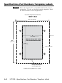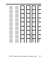
1
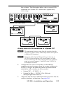
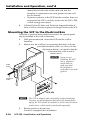
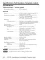
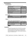
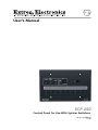
User’s Manual PRELIMINARY SCP 250 Control Panel for Use With System Switchers 68-511-01 Rev. C 11 08 Precautions Safety Instructions • English This symbol is intended to alert the user of important operating and maintenance (servicing) instructions in the literature provided with the equipment. This symbol is intended to alert the user of the presence of uninsulated dangerous voltage within the product’s enclosure that may present a risk of electric shock. Caution Read Instructions • Read and understand all safety and operating instructions before using the equipment. Retain Instructions • The safety instructions should be kept for future reference. Follow Warnings • Follow all warnings and instructions marked on the equipment or in the user information. Avoid Attachments • Do not use tools or attachments that are not recommended by the equipment manufacturer because they may be hazardous. Consignes de Sécurité • Français Ce symbole sert à avertir l’utilisateur que la documentation fournie avec le matériel contient des instructions importantes concernant l’exploitation et la maintenance (réparation). Ce symbole sert à avertir l’utilisateur de la présence dans le boîtier de l’appareil de tensions dangereuses non isolées posant des risques d’électrocution. Attention Lire les instructions• Prendre connaissance de toutes les consignes de sécurité et d’exploitation avant d’utiliser le matériel. Conserver les instructions• Ranger les consignes de sécurité afin de pouvoir les consulter à l’avenir. Respecter les avertissements • Observer tous les avertissements et consignes marqués sur le matériel ou présentés dans la documentation utilisateur. Eviter les pièces de fixation • Ne pas utiliser de pièces de fixation ni d’outils non recommandés par le fabricant du matériel car cela risquerait de poser certains dangers. Sicherheitsanleitungen • Deutsch Dieses Symbol soll dem Benutzer in der im Lieferumfang enthaltenen Dokumentation besonders wichtige Hinweise zur Bedienung und Wartung (Instandhaltung) geben. Dieses Symbol soll den Benutzer darauf aufmerksam machen, daß im Inneren des Gehäuses dieses Produktes gefährliche Spannungen, die nicht isoliert sind und die einen elektrischen Schock verursachen können, herrschen. Achtung Lesen der Anleitungen • Bevor Sie das Gerät zum ersten Mal verwenden, sollten Sie alle Sicherheits-und Bedienungsanleitungen genau durchlesen und verstehen. Aufbewahren der Anleitungen • Die Hinweise zur elektrischen Sicherheit des Produktes sollten Sie aufbewahren, damit Sie im Bedarfsfall darauf zurückgreifen können. Befolgen der Warnhinweise • Befolgen Sie alle Warnhinweise und Anleitungen auf dem Gerät oder in der Benutzerdokumentation. Keine Zusatzgeräte • Verwenden Sie keine Werkzeuge oder Zusatzgeräte, die nicht ausdrücklich vom Hersteller empfohlen wurden, da diese eine Gefahrenquelle darstellen können. Instrucciones de seguridad • Español Este símbolo se utiliza para advertir al usuario sobre instrucciones importantes de operación y mantenimiento (o cambio de partes) que se desean destacar en el contenido de la documentación suministrada con los equipos. Este símbolo se utiliza para advertir al usuario sobre la presencia de elementos con voltaje peligroso sin protección aislante, que puedan encontrarse dentro de la caja o alojamiento del producto, y que puedan representar riesgo de electrocución. Precaucion Leer las instrucciones • Leer y analizar todas las instrucciones de operación y seguridad, antes de usar el equipo. Conservar las instrucciones • Conservar las instrucciones de seguridad para futura consulta. Obedecer las advertencias • Todas las advertencias e instrucciones marcadas en el equipo o en la documentación del usuario, deben ser obedecidas. Evitar el uso de accesorios • No usar herramientas o accesorios que no sean especificamente recomendados por el fabricante, ya que podrian implicar riesgos. Warning Power sources • This equipment should be operated only from the power source indicated on the product. This equipment is intended to be used with a main power system with a grounded (neutral) conductor. The third (grounding) pin is a safety feature, do not attempt to bypass or disable it. Power disconnection • To remove power from the equipment safely, remove all power cords from the rear of the equipment, or the desktop power module (if detachable), or from the power source receptacle (wall plug). Power cord protection • Power cords should be routed so that they are not likely to be stepped on or pinched by items placed upon or against them. Servicing • Refer all servicing to qualified service personnel. There are no userserviceable parts inside. To prevent the risk of shock, do not attempt to service this equipment yourself because opening or removing covers may expose you to dangerous voltage or other hazards. Slots and openings • If the equipment has slots or holes in the enclosure, these are provided to prevent overheating of sensitive components inside. These openings must never be blocked by other objects. Lithium battery • There is a danger of explosion if battery is incorrectly replaced. Replace it only with the same or equivalent type recommended by the manufacturer. Dispose of used batteries according to the manufacturer’s instructions. Avertissement Alimentations• Ne faire fonctionner ce matériel qu’avec la source d’alimentation indiquée sur l’appareil. Ce matériel doit être utilisé avec une alimentation principale comportant un fil de terre (neutre). Le troisième contact (de mise à la terre) constitue un dispositif de sécurité : n’essayez pas de la contourner ni de la désactiver. Déconnexion de l’alimentation• Pour mettre le matériel hors tension sans danger, déconnectez tous les cordons d’alimentation de l’arrière de l’appareil ou du module d’alimentation de bureau (s’il est amovible) ou encore de la prise secteur. Protection du cordon d’alimentation • Acheminer les cordons d’alimentation de manière à ce que personne ne risque de marcher dessus et à ce qu’ils ne soient pas écrasés ou pincés par des objets. Réparation-maintenance • Faire exécuter toutes les interventions de réparationmaintenance par un technicien qualifié. Aucun des éléments internes ne peut être réparé par l’utilisateur. Afin d’éviter tout danger d’électrocution, l’utilisateur ne doit pas essayer de procéder lui-même à ces opérations car l’ouverture ou le retrait des couvercles risquent de l’exposer à de hautes tensions et autres dangers. Fentes et orifices • Si le boîtier de l’appareil comporte des fentes ou des orifices, ceux-ci servent à empêcher les composants internes sensibles de surchauffer. Ces ouvertures ne doivent jamais être bloquées par des objets. Lithium Batterie • Il a danger d’explosion s’ll y a remplacment incorrect de la batterie. Remplacer uniquement avec une batterie du meme type ou d’un ype equivalent recommande par le constructeur. Mettre au reut les batteries usagees conformement aux instructions du fabricant. Vorsicht Stromquellen • Dieses Gerät sollte nur über die auf dem Produkt angegebene Stromquelle betrieben werden. Dieses Gerät wurde für eine Verwendung mit einer Hauptstromleitung mit einem geerdeten (neutralen) Leiter konzipiert. Der dritte Kontakt ist für einen Erdanschluß, und stellt eine Sicherheitsfunktion dar. Diese sollte nicht umgangen oder außer Betrieb gesetzt werden. Stromunterbrechung • Um das Gerät auf sichere Weise vom Netz zu trennen, sollten Sie alle Netzkabel aus der Rückseite des Gerätes, aus der externen Stomversorgung (falls dies möglich ist) oder aus der Wandsteckdose ziehen. Schutz des Netzkabels • Netzkabel sollten stets so verlegt werden, daß sie nicht im Weg liegen und niemand darauf treten kann oder Objekte darauf- oder unmittelbar dagegengestellt werden können. Wartung • Alle Wartungsmaßnahmen sollten nur von qualifiziertem Servicepersonal durchgeführt werden. Die internen Komponenten des Gerätes sind wartungsfrei. Zur Vermeidung eines elektrischen Schocks versuchen Sie in keinem Fall, dieses Gerät selbst öffnen, da beim Entfernen der Abdeckungen die Gefahr eines elektrischen Schlags und/oder andere Gefahren bestehen. Schlitze und Öffnungen • Wenn das Gerät Schlitze oder Löcher im Gehäuse aufweist, dienen diese zur Vermeidung einer Überhitzung der empfindlichen Teile im Inneren. Diese Öffnungen dürfen niemals von anderen Objekten blockiert werden. Litium-Batterie • Explosionsgefahr, falls die Batterie nicht richtig ersetzt wird. Ersetzen Sie verbrauchte Batterien nur durch den gleichen oder einen vergleichbaren Batterietyp, der auch vom Hersteller empfohlen wird. Entsorgen Sie verbrauchte Batterien bitte gemäß den Herstelleranweisungen. Advertencia Alimentación eléctrica • Este equipo debe conectarse únicamente a la fuente/tipo de alimentación eléctrica indicada en el mismo. La alimentación eléctrica de este equipo debe provenir de un sistema de distribución general con conductor neutro a tierra. La tercera pata (puesta a tierra) es una medida de seguridad, no puentearia ni eliminaria. Desconexión de alimentación eléctrica • Para desconectar con seguridad la acometida de alimentación eléctrica al equipo, desenchufar todos los cables de alimentación en el panel trasero del equipo, o desenchufar el módulo de alimentación (si fuera independiente), o desenchufar el cable del receptáculo de la pared. Protección del cables de alimentación • Los cables de alimentación eléctrica se deben instalar en lugares donde no sean pisados ni apretados por objetos que se puedan apoyar sobre ellos. Reparaciones/mantenimiento • Solicitar siempre los servicios técnicos de personal calificado. En el interior no hay partes a las que el usuario deba acceder. Para evitar riesgo de electrocución, no intentar personalmente la reparación/mantenimiento de este equipo, ya que al abrir o extraer las tapas puede quedar expuesto a voltajes peligrosos u otros riesgos. Ranuras y aberturas • Si el equipo posee ranuras o orificios en su caja/alojamiento, es para evitar el sobrecalientamiento de componentes internos sensibles. Estas aberturas nunca se deben obstruir con otros objetos. Batería de litio • Existe riesgo de explosión si esta batería se coloca en la posición incorrecta. Cambiar esta batería únicamente con el mismo tipo (o su equivalente) recomendado por el fabricante. Desachar las baterías usadas siguiendo las instrucciones del fabricante. 安全须知 • 中文 警告 这个符号提示用户该设备用户手册中 有重要的操作和维护说明。 电源 • 该 设 备 只 能 使 用 产 品 上 标 明 的 电 源 。 设 备 必须使用有地线的供电系统供电。 第三条线 (地线)是安全设施,不能不用或跳过。 这个符号警告用户该设备机壳内有暴 拔掉电源 • 为安全地从设备拔掉电源,请拔掉所有设备后 或桌面电源的电源线,或任何接到市电系统的电源线。 露的危险电压,有触电危险。 电源线保护 • 妥善布线, 避免被踩踏,或重物挤压。 注意 阅读说明书 • 用 户 使 用 该 设 备 前 必 须 阅 读 并 理 解所有安全和使用说明。 保存说明书 • 用户应保存安全说明书以备将来使 用。 遵守警告 • 用户应遵守产品和用户指南上的所有安 全和操作说明。 维护 • 所有维修必须由认证的维修人员进行。 设备内部没 有用户可以更换的零件。为避免出现触电危险不要自己 试图打开设备盖子维修该设备。 通风孔 • 有些设备机壳上有通风槽或孔,它们是用来防止 机内敏感元件过热。 不要用任何东西挡住通风孔。 锂电池 • 不正确的更换电池会有爆炸的危险。 必须使用与 厂家推荐的相同或相近型号的电池。 按照生产厂的建 议处理废弃电池。 避免追加 • 不要使用该产品厂商没有推荐的工具或 追加设备,以避免危险。 FCC Class A Notice This equipment has been tested and found to comply with the limits for a Class A digital device, pursuant to part 15 of the FCC Rules. Operation is subject to the following two conditions: (1) this device may not cause harmful interference, and (2) this device must accept any interference received, including interference that may cause undesired operation. The Class A limits are designed to provide reasonable protection against harmful interference when the equipment is operated in a commercial environment. This equipment generates, uses, and can radiate radio frequency energy and, if not installed and used in accordance with the instruction manual, may cause harmful interference to radio communications. Operation of this equipment in a residential area is likely to cause harmful interference, in which case the user will be required to correct the interference at his own expense. N This unit was tested with shielded cables on the peripheral devices. Shielded cables must be used with the unit to ensure compliance with FCC emissions limits. SCP 250 • Safety and Compliances SCP 250 • Safety and Compliances Table of Contents Chapter One • Introduction..................................................... 1-1 About the SCP 250..................................................................... 1-2 Features......................................................................................... 1-2 Chapter Two • Installation and Operation. .................. 2-1 Installation Overview. .............................................................. 2-2 Preparing the Site, Installing the Electrical Box............... 2-2 Rear Panel Connectors and Switches. ................................. 2-4 Cabling........................................................................................... 2-5 Front Panel Features and Operation.................................... 2-8 Testing/Troubleshooting.......................................................... 2-9 Mounting the SCP to the Electrical Box............................ 2-10 Appendix A • Specifications, Part Numbers, Template, Labels..............................................................................A-1 Specifications...............................................................................A-2 Part Numbers...............................................................................A-3 Included parts.........................................................................A-3 Accessories..............................................................................A-3 Cables......................................................................................A-3 Template........................................................................................A-3 Labeling Buttons on the SCP..................................................A-5 Button-Label Generator software.........................................A-5 Installing the software........................................................... A-5 Using the software to make labels....................................... A-5 Label templates.......................................................................A-6 All trademarks mentioned in this manual are the properties of their respective owners. 68-511-01 C 11 08 SCP 250 • Table of Contents i Table of Contents, cont’d ii SCP 250 • Table of Contents SCP 250 1 Chapter One Introduction About the SCP 250 Features Introduction About the SCP 250 The Extron SCP 250 is a hard wired remote control panel for use with Extron system switchers. Refer to the appropriate switcher’s user’s manual for information on installing, operating, and setting up the switcher. N The system switcher cannot be configured from an SCP control panel. All switcher setup must be done from the switcher’s front panel or via RS-232. The SCP 250 replicates the front panel controls of the System 7SC switcher (display controls, input selection buttons, and room function buttons), and it can also be used with the System 5cr Plus. It accepts signals from the switcher's remote control, and includes an audio volume control. The SCP 250 can be mounted in or on a wall or furniture in a 3-gang junction box (for an installation that meets UL safety standards) or mud ring. Features Black or white white faceplates — SCP control panels are offered in three shades for integration into a variety of environments. System expandability — The SCPs can be daisy chained together in any combination to provide control of a System 7SC or newer switcher from several locations. Furniture and wall mountability — The control panels can be mounted onto or in furniture or walls. Label windows — Customized labels can be created and inserted into the windows that are set into the faceplates. 1-2 SCP 250 • Introduction SCP 250 2 Chapter Two Installation and Operation Installation Overview Preparing the Site, Installing the Electrical Box Rear Panel Connectors and Switches Cabling Front Panel Features and Operation Testing/Troubleshooting Mounting the SCP to the Electrical Box Installation and Operation Installation Overview To install and set up an SCP control panel, follow these steps: 1 Turn the equipment off. Make sure that the SCP and the system switcher are disconnected from the power source. 2 Run cables through the wall or furniture where the SCP will be installed. 3 Prepare the site and install and ground the electrical box (if one will be used) or mounting bracket/mud ring. 4 Set the identification DIP switches on the circuit board. 5 Wire the 5-pole captive screw connectors on both ends of the cable that was installed in the wall or furniture in step 2. 6 Plug the wired connectors into the receptacles on the back of the SCP and on the rear panel of the system switcher. 7 Restore power to the system switcher. 8 Press an input selection button. If the corresponding LED does not light or the switch to the selected input is not made, disconnect power from the switcher and verify correct connector wiring at both ends of the cable. 9 Mount the SCP in the wall box or furniture, and make sure the faceplate is tied to an earth ground to prevent damage caused by electrostatic discharge. 10 Reconnect the switcher to the A/C power source. Preparing the Site, Installing the Electrical Box A mud ring is included with each SCP 250. However, for an installation that meets UL safety requirements, you must use a UL Listed junction box instead of a mud ring/mounting bracket. The box must be at least 1.5" (3.8 cm) to contain both the SCP’s electrical components and the cables. The electrical box can be attached to wall studs or to furniture, or the SCP can be mounted in areas of walls or furniture without studs if using an Extron 3-gang mounting bracket, part #70‑519‑32. Bracket installation instructions are included with the brackets. Use the template provided in appendix A as a guide to mark and cut the hole in the wall or furniture in which the SCP will be installed. The template includes the recommended 0.1" (0.25 cm) clearance on all sides of the electrical wall box to allow room for the raised areas surrounding the knockouts. 2-2 SCP 250 • Installation and Operation 3-gang wall box grounding.eps 1. Cut out the center portion of the template. Cut up to the dashed line if using an electrical box, or cut up to the dotted line if an electrical box will not be used. 2. If wall-mounting the SCP, locate a stud to which the wall box will be attached. 3. Place the wall box or mounting bracket against the installation surface; mark the guidelines and for the opening on the wall or furniture and cut it out; or... Using the provided template, mark and cut out the opening on the wall/furniture. 4. Insert the wall box (if used) into the wall, and attach the wall box to the wall stud (2" x 4") or furniture with nails or Wall Stud screws, leaving the front edge Screws or Nails flush with the wall surface, as Cable shown in Clamp the illustration at right. Foil Shield Installation Cable Braided Shield Screw To attach the wall box to wood, use four #8 to #10 wood or sheet metal screws. A minimum of 1/2" (1.3 cm) of screw threads must penetrate the wood. If the wood is a 2 x 4, such as a wall stud, 10-penny or larger nails can be used. To attach the electrical wall box to metal, use four #8 or #10 sheet metal screws (self-tapping) or #8 or #10 machine bolts with matching nuts. If mounting brackets will be used instead of a wall box, follow the mounting instructions that came with the brackets. 5. Feed cables through the wall box’s punch-out holes, and secure them with cable clamps to provide strain relief. SCP 250 • Installation and Operation 2-3 Installation and Operation, cont’d 6. Exposed cable shields (braids or foil) are potential sources of short circuits. Trim back and/or insulate shields with heat shrink. To prevent short circuits, the outer foil shield can be cut back to the point where the cable exits the cable clamp. Connect both braided and foil shields to an equipment ground at the other end of the cable. C Rear Panel Connectors and Switches 1 1 2 J1 J2 1 8 7 6 5 4 3 2 1 SCP 250 SW13 3 a and b Communications connectors — Use these connectors to connect SCPs together and to connect them to the switcher. Both connectors function the same way, so they are interchangeable. Plug one end of an Extron CTL Series Comm-Link cable into one of these 3.5 mm, 5-pin captive screw connectors, and plug the other end into the system switcher (or to the next SCP closer to the switcher, if daisy chained). If this SCP is at the end of a daisy chain of SCPs, do not use the other connector. If this SCP is in the middle of a chain of SCPs, plug one end of a Comm-Link cable into the second captive screw connector, and plug the other end into the next SCP further away from the switcher. 2-4 SCP 250 • Installation and Operation c DIP switches — Set these switches to indicate what model of system switcher the SCP is attached to. 1 2 3 4 5 6 7 8 1, 2, 3, 4 — Input number identification — See the table below for the appropriate settings for each SCP address. 5, 6, 7 — Not used — Keep these set to the closed/up position. 8 — Switcher model identification Closed/up — System 7SC Open/down — System 5cr Plus 1 2 1 DIP Switch Number SCP Address 3 4 5 6 7 8 * 1 0 0 0 0 0 0 * 2 * 3 1 1 0 0 0 0 0 * 4 * 5 1 0 1 0 0 0 0 * 6 * 7 1 1 1 0 0 0 0 * 8 * 9 1 0 0 1 0 0 0 * 10 * 11 1 1 0 1 0 0 0 * 12 * 13 1 0 1 1 0 0 0 * 14 * 15 1 1 1 1 0 0 0 * 16 For all switches 0 = closed (up) 1 = open (down) *For switch 8 0 = System 7SC 1 = System 5cr Plus On each SCP in a system, switch 8 must be set to the correct position for the switcher model. SCP DIP switch assignments Cabling For each SCP to be connected to a system switcher, set the rear panel DIP switches, then follow these steps: 1. If it wasn’t done when the wall box was installed, cut a length of Extron CTL Series Comm-Link cable to go between the switcher and the SCP. 2. Using the following diagrams as a guide, attach a 3.5 mm, 5-pole captive screw connector to each end of the cable. SCP 250 • Installation and Operation 2-5 Installation and Operation, cont’d Wire both ends of the cable identically (pin A to pin A, pin B to pin B, etc.). AUX System 5 AUX port A B C D E IR signals in (violet) Gnd (black) Comm signal (white) Gnd (drain) +12V (red) Port on SCP circuit board A B C D E IR signals in (violet) Gnd (black) Comm signal (white) Gnd (drain) +12V (red) Wiring for use with a System 5cr Plus switcher SCP/AAP CONTROL E D CB A E D CB A 1 2 A B C D E Ground (shield/drain) Comm. signal (white) Ground (black) +12VDC (red) To / from SCP 250 Wiring for use with a System 7SC switcher Conductor gauges in Extron Comm-Link cables red and black single strands 18 AWG white and violet shielded single strands 22 AWG drain wire 24 AWG Connectors are included with each SCP, but the cable must be purchased separately. See page A-3 for cable part numbers. The cable should not exceed 300 feet (91.4 meters) in length. 2-6 3. Plug one end of the cable into one of the SCP’s communications connectors, and plug the other end into the switcher (System 5cr Plus or System 7SC). 4. Cut a cable and attach connectors to it for each additional SCP that will be connected in a daisy chain. Up to a total of 16 SCPs can be daisy chained together and connected to the system switcher. 5. Plug one end of the cable into the SCP’s other communications connector, and plug the other end into a communications connector on the next SCP closer to SCP 250 • Installation and Operation the switcher. The illustration below shows several SCPs connected to a System 7SC switcher in a typical daisy chain setup. OUTPUTS INPUTS Anaheim, CA 100- 240 50/60 Hz 1.3A MAX. R R-Y H/HV R R-Y H/HV R R-Y H/HV R R-Y H/HV R R-Y H/HV R R-Y H/HV G/Y VID V G/Y VID V G/Y VID V G/Y VID V G/Y VID V G/Y VID V 1 2 B/C B-Y L 1 R 3 B/C B-Y AUDIO IN L 2 R L 3 R 4 B/C B-Y B/C B-Y AUDIO OUT FIXED L 4 R L 5 R L 6 R L R L 5 R 1 G B H/HV V 6 B/C B-Y B/C B-Y SCP/AAP CONTROL E D CB A E D CB A VARIABLE R 2 RS-232 RGB 1 2 3 4 5 6 7 E DCBA A B CD E A B CD E CONTACT CLOSURE RELAY 1 RELAY 2 DISPLAY PWR SENSOR IR COMM A B C D E F G H I J PROJ CONTROL System 7SC Rear Panel 1 J1 1 J1 1 J2 J2 1 8 7 6 5 4 3 2 1 J2 1 8 7 6 5 4 3 2 1 SW13 1 J1 8 7 6 5 4 3 2 1 SW13 SW13 SCP 250 SCP 250 J1 1 1 8 7 6 5 4 3 2 1 SCP 250 1 J2 SW13 J1 1 J2 8 7 6 5 4 3 2 1 SW13 SCP 250 A daisy chain of SCPs connected to a System 7SC N The maximum distance away from the switcher that the last SCP (or other device) in the daisy chain can be placed is 300 feet (91.4 meters). N Each port of the System 7SC switcher provides up to 12 VDC for powering the SCP control panels or other devices. However, the total load for both ports combined must not exceed 1 ampere. Each SCP uses 12 VDC at 0.06 ampere (60 mA). 6. Another device such as an interface or distribution amplifier can receive power from the system switcher via an SCP, as long as the following limits for the total load attached to each switcher are not exceeded: • System 7SC — 12 VDC, 1 A • System 5cr Plus — 12 VDC, 0.5 A (500 mA) (each port provides 250 mA) 7. After each SCP has been cabled and tested, mount it into the wall box, brackets, or furniture. See page 2-10. SCP 250 • Installation and Operation 2-7 Installation and Operation, cont’d Front Panel Features and Operation 1 2 DISPLAY POWER 3 AUDIO MUTE MODE MAX/ IR MIN VOLUME SCP 250 4 a 5 Display control buttons (Power, Mute, Mode) and LEDs — The settings of the display control functions are customized for each projector. These buttons function only after they have been programmed on the System 7SC or System 5cr Plus. Display power (Power) button and LED — Pressing this button turns the projector’s power on/off. It may also be tied to a Room function (System 7SC only) if programmed to do so. The LED lights when projector power is on, and it blinks during projector power-up/power-down. The power-up/ down delay times are set via the software that is included with the switcher. Display mute (Mute) button — Press this button to turn the projector’s “mute” function on or off (to turn off/ on the displayed image) once the Mute button has been programmed for use with the projector. Mode button — For the System 5cr Plus, this button can be programmed to switch the mode of the projector between computer-video (RGB), S-video, and composite video. For the System 7SC, this button can be programmed to execute any RS-232 or IR command. b 2-8 Volume control knob and LED — Turn this knob to adjust the audio volume. For the System 7SC this affects the Variable (preamp) audio output, not the fixed output. There is no physical limit to this knob’s rotation. The LED blinks when the knob has reached its functional minimum or maximum limit. SCP 250 • Installation and Operation c IR signal pickup device — Like the IR signal pickup device on the switcher, this receives commands from the IR 401 or IR 701 remote control and sends them to the switcher. Infrared signals from other devices are not passed on through the switcher. The IR remote must be within 50 feet (15.2 meters) of and pointed directly at this device for best results. N Switcher configuration must be done using the front panel controls or RS-232 control. Configuration cannot be done from the IR 401 or IR 701. d Room control buttons and LEDs — Room buttons control the switcher’s Relay ports, which control “room” functions–items such as room lighting, window coverings, and display screens–via momentary or latching contact. The Room 1 button can be used for both the System 5cr Plus and the System 7SC, the Room 2 button is used only with the System 7SC. These contacts may be used to control any equipment as long as the contact specifications of a total of 24 V at 1 A are not exceeded. The Room buttons light while the room functions are active (on). Refer to the System 5cr Plus User’s Manual and the System 7SC User’s Manual for information on the room function/Relay ports). e Input selection buttons and LEDs — These buttons correspond to the input selection buttons on the front of the switcher. See page A-7 in this manual for an example of how the SCP 250’s input selections buttons are assigned depending on the model of switcher the SCP is connected to. Testing/Troubleshooting Before installing the control panel into the wall or furniture, test the system to make sure that the connections are correct and the SCP is working correctly. 1. Connect the cables between the switcher and the SCP(s). 2. Power on the switcher. 3. Press the input selection buttons on the SCP, and watch the LEDs on the switcher to see if the system switches to the desired input(s). N The connections between the SCP and the system switcher can be tested even if input/output devices are not available. • If the SCP’s input selection LED does not light, check the captive screw connector wiring at both the switcher and the SCP. If the conductor assignments are not the same at both ends, the SCP will not turn on, and circuits may be damaged if power is applied to the wrong pole. Verify that the connectors are wired SCP 250 • Installation and Operation 2-9 Installation and Operation, cont’d identically at both ends of the cable and that the faceplate is connected to an earth ground via the wall box or directly. • If power is present at the SCP, but the switcher does not respond to the SCP’s controls, make sure the SCP’s DIP switch settings are correct. 4. Call the Extron S3 Sales and Technical Support Hotline if there is still no switcher response to changes made at the SCP. Mounting the SCP to the Electrical Box Once the system has been cabled and tested, the control panel can be installed in the wall or furniture. 1. With power removed, insert the SCP into the wall or furniture. 2. Mount it to the wall box (or mounting brackets) with the provided machine screws (as shown in the illustration below), or attach it directly to the furniture with wood or metal screws. N If you are not installing the SCP into a grounded metal wall box, make sure that the faceplate is grounded to an earth ground. Cable Clamp Installation Cable IR DIO AU / MAX Y LA DISP E MUT MIN ME VO LU E MOD WER PO 50 P2 SC SCP 250 N The SCP is shipped with a mounting bracket (mudring). However, for an installation that meets UL standards for safety, the SCP should be installed in a UL Listed electrical junction box, which must be purchased separately. 3. 2-10 Restore power to the devices. You have completed the installation. SCP 250 • Installation and Operation SCP 250 A Appendix A Specifications, Part Numbers, Template, Labels Specifications Part Numbers Template Labeling Buttons on the SCP Specifications, Part Numbers, Template, Labels Specifications Control/remote — control panels IR controller module��������������������� IR 701 (optional) General Power���������������������������������������������� 12 VDC, at 60 mA, from a System 7SC or System 5cr Plus switcher Temperature/humidity���������������� Storage: -40 to +158 °F (-40 to +70 °C) / 10% to 90%, noncondensing Operating: +32 to +122 °F (0 to +50 °C) / 10% to 90%, noncondensing Mounting Furniture mount���������������� Furniture/wall mountable with included faceplate and included mounting bracket or optional 3-gang electrical box Enclosure type������������������������������� Metal Enclosure dimensions Faceplate����������������������������� 4.5" H x 6.4" W x 0.1" D (3-gang) (11.4 cm H x 16.3 cm W x 0.3 cm D) Box��������������������������������������� 3.75" H x 5.4" W x 3.5" D (9.5 cm H x 13.8 cm W x 8.9 cm D) Circuit board���������������������� 2.7" H x 5.3" W x 0.9" D (6.9 cm H x 13.5 cm W x 2.3 cm D) (Allow at least 1.5" (3.8 cm) depth in the wall or furniture. Depth excludes connectors and knobs.) Product weight������������������������������ 0.5 lbs (0.2 kg) Shipping weight���������������������������� 3 lbs (2 kg) Vibration����������������������������������������� ISTA 1A in carton (International Safe Transit Association) Regulatory compliance Safety����������������������������������� CE, CUL, UL EMI/EMC�������������������������� CE, FCC Class A as components of the System 7SC MTBF����������������������������������������������� 30,000 hours Warranty����������������������������������������� 3 years parts and labor N All nominal levels are at ±10%. N Specifications are subject to change without notice. 7.6-102808-D4 A-2 SCP 250 • Specifications, Part Numbers, Template, Labels Part Numbers Included parts These items are included in each order for an SCP 250: Included parts Replacement part number SCP 250 (black, white) 60-356-02, -03 MR 300 3-gang mounting bracket (mudring) (black, white) 70-519-32, -33 3.5 mm, 5-pole captive screw connectors 10-319-01LF Grounding wire User’s manual Accessories Accessories JB 325 three-gang, 2.5" deep junction box Part number 980083 Cables This is the type of cable recommended for connecting a system switcher to one or more SCP control panels: CTL Series (Comm-Link) cables Part number CTLP/1000 plenum (1000 feet/300 meters) 22-119-03 CTL/1000 non-plenum (1000 feet/300 meters) 22-148-03 N These cables are also available in 500 foot (150 m) lengths. Template Use the following template (which is NOT full size) as a guide to mark and cut the hole in the wall or furniture through which the SCP control panel will be installed. The template includes the recommended 0.1" (0.25 cm) clearance on all sides of the optional 3-gang electrical wall box to allow room for the raised areas surrounding the knockouts. See the installation/operation chapter for installation details. SCP 250 • Specifications, Part Numbers, Template, Labels A-3 Specifications, Part Numbers, Template, Labels N Rotate the template 90° to install the SCP in the correct orientation. Do not cut directly from this template. Mark the measurements on the wall/furniture. Cut-Out Template for Extron's SCP 250 4.50" (11.43 cm) 2.8" (7.13 cm) 6.40" (16.3 cm) Top Panel SURFACE CUT-OUT AREA FOR FURNITURE MOUNT 5.4" (13.73 cm) Location of SCP 250 To install SCP 250 directly into furniture, cut along this line. TEMPLATE IS NOT FULL SIZE. A-4 SCP 250 • Specifications, Part Numbers, Template, Labels Labeling Buttons on the SCP The SCP 250 has translucent panels (“windows”) behind which customized labels can be inserted. To remove a panel, 1. Insert the head of a small Phillips screwdriver into the hole in one end of the panel. 2. Gently slide the tab on the edge of the panel out of the recess in the SCP’s faceplate. Premade templates and blank templates for the SCPs’ label windows are printed in this chapter. However, you can easily create, customize, and print labels by using the Button-Label Generator software or any Brother P-Touch® labeller. Button-Label Generator software The Extron Button-Label Generator program (Buttons.exe) is shipped with the System 7SC, and it is also available on the Extron Web site. This program is used to create and print labels that can be placed in slots above/below buttons on the SCPs. The program occupies approximately 0.5 MB of disk space. It can be run on a diskette from a floppy drive, but it is more convenient to load and run the program from a hard drive. Installing the software This program is installed at the same time and from the same disk as the System 7SC control program. See the System 7SC User’s Manual for details. The Button-Label Generator program can be installed separately via the Download page of the Extron Web site (http://www.extron.com). Follow the on-screen directions if you install the program from the Web site. By default, the Windows installation creates a C:\BUTTONS directory, and it places an icon (Button-Label Generator) into a group or folder named “Extron Electronics”. Using the software to make labels 1. To run the Button-Label Generator program, double-click on the Button-Label Generator icon (shown at left) in the Extron Electronics group or folder, and click OK when prompted. 2. Under System selection, choose the SCP 250. The button label editing area changes to reflect the number and arrangement of buttons on the device. 3. Using normal Windows controls, you can create and print labels for the front panels of the SCPs. 4. Cut the label strips to the appropriate length, and install them in the SCP’s windows. SCP 250 • Specifications, Part Numbers, Template, Labels A-5 Specifications, Part Numbers, Template, Labels For information about using the program, you can access a help file by clicking on the Help menu on the main screen and choosing Use Help. The picture below shows how the Button-Label Generator screen looks when set for the SCP 250. SCP 250 button label screen Each input, display, and room control can be labeled with names, alphanumeric characters, or bitmapped pictures. Each button’s label can contain from 1 to 3 lines of text (or none). Each line provides a choice of font sizes and text placement. Pictures can be selected either from the Device Palette or a user-supplied graphic file. User-supplied graphics should be icon (.ICO) or bitmap (.BMP) files. Files called TEST.BMP and DEMO_BTN.DAT are installed with this program as examples. Label templates On the following page is a full-sized template for the labels. Feel free to photocopy it, write button information in each area of the blank template as desired, cut the strips out, and insert the strips in the label window. A-6 SCP 250 • Specifications, Part Numbers, Template, Labels SCP 250 • Specifications, Part Numbers, Template, Labels A-7 ROOM 2 1 ROOM 1 2 For use with a System 5cr Plus switcher ROOM 1 For use with a System 7SC switcher 3 2 4 3 5 4 n/a 5 n/a 6 n/a 7 Specifications, Part Numbers, Template, Labels A-8 SCP 250 • Specifications, Part Numbers, Template, Labels Extron’s Warranty Extron Electronics warrants this product against defects in materials and workmanship for a period of three years from the date of purchase. In the event of malfunction during the warranty period attributable directly to faulty workmanship and/or materials, Extron Electronics will, at its option, repair or replace said products or components, to whatever extent it shall deem necessary to restore said product to proper operating condition, provided that it is returned within the warranty period, with proof of purchase and description of malfunction to: USA, Canada, South America, and Central America: Extron USA 1001 East Ball Road Anaheim, CA 92805 U.S.A. Europe, Africa, and the Middle East: Extron Europe Hanzeboulevard 10 3825 PH Amersfoort The Netherlands Asia: Extron Asia 135 Joo Seng Road #04-01 PM Industrial Bldg. Singapore 368363 Singapore Japan: Extron Japan Kyodo Building, 16 Ichibancho Chiyoda-ku, Tokyo 102-0082 Japan China: Extron China 686 Ronghua Road Songjiang District Shanghai 201611 China Middle East: Extron Middle East Dubai Airport Free Zone F12, PO Box 293666 United Arab Emirates, Dubai This Limited Warranty does not apply if the fault has been caused by misuse, improper handling care, electrical or mechanical abuse, abnormal operating conditions or nonExtron authorized modification to the product. If it has been determined that the product is defective, please call Extron and ask for an Applications Engineer at (714) 491-1500 (USA), 31.33.453.4040 (Europe), 65.6383.4400 (Asia), or 81.3.3511.7655 (Japan) to receive an RA# (Return Authorization number). This will begin the repair process as quickly as possible. Units must be returned insured, with shipping charges prepaid. If not insured, you assume the risk of loss or damage during shipment. Returned units must include the serial number and a description of the problem, as well as the name of the person to contact in case there are any questions. Extron Electronics makes no further warranties either expressed or implied with respect to the product and its quality, performance, merchantability, or fitness for any particular use. In no event will Extron Electronics be liable for direct, indirect, or consequential damages resulting from any defect in this product even if Extron Electronics has been advised of such damage. Please note that laws vary from state to state and country to country, and that some provisions of this warranty may not apply to you. Extron USA - West Headquarters +800.633.9876 Inside USA / Canada Only +1.714.491.1500 +1.714.491.1517 FAX Extron USA - East Extron Europe Extron Asia Extron Japan Extron China Extron Middle East +800.633.9876 +800.3987.6673 +800.7339.8766 +81.3.3511.7655 +81.3.3511.7656 FAX +400.883.1568 +971.4.2991800 +971.4.2991880 FAX +1.919.863.1794 +1.919.863.1797 FAX +31.33.453.4040 +31.33.453.4050 FAX +65.6383.4400 +65.6383.4664 FAX Inside USA / Canada Only Inside Europe Only Inside Asia Only © 2008 Extron Electronics. All rights reserved. Inside China Only +86.21.3760.1568 +86.21.3760.1566 FAX