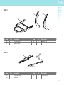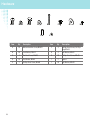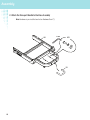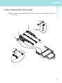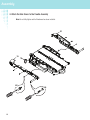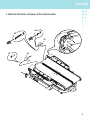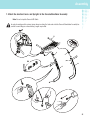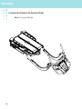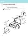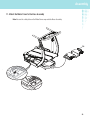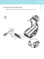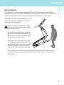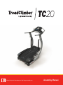
1
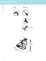
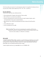
Manual en Español Latino Americano: http://support.nautilus.com
Assembly Manual
Table of Contents
Important Safety Instructions .................................................................................................3
Specifications and Tools..........................................................................................................4
Before Assembly......................................................................................................................5
Parts .......................................................................................................................................6
Hardware ................................................................................................................................8
Assembly.................................................................................................................................9
Adjustments..........................................................................................................................23
If you have questions or problems with your product, please call 1 (800) 605–3369.
Nautilus, Inc., (800) NAUTILUS / (800) 628-8458, www.NautilusInc.com - Customer Service: North America (800) 6053369, [email protected] | outside U.S. +01-360-859-5180, [email protected] | Printed in China | ©
2011 Nautilus, Inc., All rights reserved. ™ and ® indicate a trademark or registered trademark. Nautilus, Inc. (www.
NautilusInc.com) trademarks include NAUTILUS®, BOWFLEX®, SCHWINN®, TreadClimber® and UNIVERSAL® and
respective logos. Other trademarks are the property of their respective owners.
2
Important Safety Instructions
This icon means a potentially hazardous situation which, if not avoided, could result in death or serious injury.
Obey the following warnings:
Read and understand all Warnings on this machine.
Carefully read and understand the Assembly Manual.
• Keep bystanders and children away from the product you are assembling at all times.
• Do not connect power supply to the machine until instructed to do so.
• Do not assemble this machine outdoors or in a wet or moist location.
• Make sure assembly is done in an appropriate work space away from foot traffic and exposure to bystanders.
• Some components of the machine can be heavy or awkward. Use a second person when doing the assembly steps
involving these parts. Do not do steps that involve heavy lifting or awkward movements on your own.
• Set up this machine on a solid, level, horizontal surface.
• Do not try to change the design or functionality of this machine. This could compromise the safety of this machine
and will void the warranty.
• If replacement parts are necessary, use only genuine replacement parts and hardware supplied by Nautilus. Failure
to use genuine replacement parts can cause a risk to users, keep the machine from operating correctly and void the
warranty.
• Do not use until the machine has been fully assembled and inspected for correct performance in accordance with the
Owner’s Manual.
• Read and understand the complete Owner’s Manual supplied with this machine before first use. Keep the Owner’s and
Assembly Manuals for future reference.
• Do all assembly steps in the sequence given. Incorrect assembly can lead to injury or malfunctioning of the machine.
3
Specifications and Tools
Included
Not Included
5 mm
#2
13 mm
(recommended)
55.2”
(140.3 cm)
55” (139.7 cm)
4
31.5” (80 cm)
Before Assembly
Select the area where you are going to set up and operate your machine. For safe operation, the location must be on a
hard, level surface. Allow a minimum workout area of 70.5” x 134” (179.1 cm x 340.4 cm).
Basic Assembly Tips
Follow these basic points when you assemble your machine:
• Read and understand the “Important Safety Instructions” before assembly.
• Collect all the pieces necessary for each assembly step.
• Using the recommended wrenches, turn the bolts and nuts to the right (clockwise) to tighten, and the
left (counterclockwise) to loosen, unless instructed otherwise.
• When attaching 2 pieces, lightly lift and look through the bolt holes to help insert the bolt through the
holes.
• The assembly requires 2 people.
• Do not use any power tools for assembly.
Note: The TreadClimber® fitness machine is designed to plug into a grounded, non-GFI outlet only.
To determine if your outlet or circuit breaker is GFI, look for a test and reset button on them. If they
have the test and reset button, it is a GFI outlet or circuit breaker.
Machine Mat
The Bowflex® TreadClimber® Machine Mat is an optional accessory that helps keep your workout area clear and adds
a layer of protection to your floor. The rubber machine mat provides a non-slip, rubber surface which limits static
discharge and reduces the possibility of display or running errors. If possible, put your Bowflex® TreadClimber®
Machine Mat in your selected workout area before you begin assembly.
To order the optional machine mat, go to: www.bowflex.com, or call 1 (800) 605–3369.
5
Parts
( 4 BOXES )
BOX 1
1
4
2
5
3
6
13
11
14
8
1
12
2
7
4
10
9
3
Item
Qty
1
1
2
15 1
3
Description
Item
Qty
Description
13
1
Hardware Card
Console / Handlebar Assembly
8
Junction Cover, Right14
9
1
1
Junction Cover, Left
10
1
4
1
Rear Cover
11
1
Power Cord 12
5
1
Bowflex® Weight Loss Plan
12
1
Transport Handle
6
1
Document Kit
13
2
Cylinder
7
1
Lubrication Kit
14
1
Motor Cover
11
20
Heart Rate Strap
19
Safety Key
21
BOX 2
15
17
19
18
16
6
Item
Qty
15
1
Description
Item
Qty
Description
Treadle Assembly
17
18
21
Parts
BOX 3
17
18
16
4
2
5
3
6
13
11
Item
16
17
Qty
12
1
1
Description
Base Assembly
8
Item
Qty
Description
18
1
Upright, Left
10
Upright, Right
7
9
BOX 4
20
19
21
Item
Qty
19
1
20
2
Hardware
Description
Side Cover, Right
17
Pivot Cover
18
Item
Qty
21
1
Description
Side Cover, Left
7
Hardware
A
B
E
F
G
Item
Qty
Description
H
G
H
Item
Qty
Description
A
16
Button Head Hex Screw, M8x20
F
8
Phillips Head Screw, Self Tapping M4x16
B
20
Lock Washer, M8x14
G
4
Flat Washer, M8x24
C
4
Hex Head Screw, M8x20
H
10
Phillips Head Screw, M4x10
D
16
Flat Washer, M8x18
I
2
Spacer
E
2
Phillips Head Screw, M4x40
J
10
Flat Washer, M4x10
F
8
D
C
I
J
Assembly
Some components of the machine can be heavy or awkward. Use a second person when doing the assembly
steps involving these parts. Do not do steps that involve heavy lifting or awkward movements on your own.
1. Cut open the end of Box 2 and move the Treadle Assembly into your new fitness area
Note: Do not cut the Shipping Zip-Tie until instructed.
15
9
Assembly
2. Attach the Transport Handle to the Base Assembly
Note: Hardware is pre-installed and not on Hardware Card (*).
16
5 mm
X2
*
*
12
10
*
Assembly
3. Attach the Treadle Assembly to the Base Assembly
Note: Do not crimp the Lower Input/ Output (I/O) Cable. Once attached, cut the Shipping Zip-Tie at the front
of the Treadles.
13 mm
X4
C
B
G
15
11
Assembly
4. Attach the Side Covers to the Treadle Assembly
Note: Do not fully tighten until all hardware has been installed.
21
19
X6
X4
F
H
#2
#2
12
J
Assembly
5. Attach the Pivot Covers and Spacers to the Treadle Assembly
X2
X4
J
H
#2
E
J
20
#2
20
X2
I
13
Assembly
6. Insert the Lower I/O Cable into the Base Assembly and then Route to Front.
Note: Be sure to route the cable into the side opening of the Base Assembly. Do not crimp the
Lower I/O Cable.
14
Assembly
7. Attach the Junction Covers and Uprights to the Console/Handlebar Assembly
Note: Do not crimp the Console I/O Cable.
In order to avoid possible serious injury, when inserting the tube ends into the Console/Handlebar Assembly be
careful to avoid fingers or hands being caught or pinched.
8
2
3
X6
B
5 mm
D
18
17
A
15
Assembly
8. Connect the I/O Cable to the Console I/O Cable
Note: Do not crimp the I/O Cable.
16
Assembly
9. Attach the Console/Handlebar/Upright Assembly to the Base Assembly
Note: Do not crimp the I/O Cables. This step may require two people.
In order to avoid possible serious injury, when inserting the tube ends into the Base Assembly be careful to
avoid fingers or hands being caught or pinched.
X10
B
5 mm
D
A
17
Assembly
10. Attach Cylinders to Treadles and then Uprights
Note: The settings dial on the cylinders must be up, with the white arrow to the inside of the machine.
Attach to Treadles before the Uprights.
* Hardware is pre-installed and not on Hardware Card.
The Treadles do not have a locking mechanism and can move freely. Take care not to allow harm or injury to
occur when lifting the Treadles.
13
13
X4
*
5 mm
18
*
*
Assembly
11. Attach the Motor Cover to the Base Assembly
Note: Be sure the safety tabs on the Motor Cover snap onto the Base Assembly.
14
19
Assembly
12. Secure the Motor Cover to the Base Assembly
X2
F
#2
20
Assembly
13. Attach the Rear Cover to the Treadle Assembly
Note: Be sure the safety tabs on the upper-inside of the Rear Cover snap onto the Base Assembly.
X2
H
#2
4
21
Assembly
14. Connect Power Cord to Treadle Assembly
Note: The TC20 TreadClimber® fitness machine is designed to plug directly into a properly wired and
grounded three prong 120V outlet. If you connect the machine to an outlet with GFI (ground fault
interrupt) or AFI (arc fault interrupt), machine operation can cause the circuit to trip.
11
15. Final Inspection
Inspect your machine to ensure that all fasteners are tight and components are properly assembled.
Do not use until the machine has been fully assembled and inspected for correct performance in accordance
with the Owner’s Manual.
22
Adjustments
Moving Your Machine
The TreadClimber® fitness machine weighs approximately 218 lbs (98.9 kg) when fully assembled and requires
caution when being moved. Use the Transport Handle found under the front of the machine to move it. To get access to
the Transport Handle, turn the Levelers until you have sufficient clearance between the machine and floor.
Your machine can be rolled on the transport wheels to a new
location. Lower your machine slowly into its new location
without injury to your head or fingers.
Do not use the uprights, handlebars, or the Console
to lift or move the machine. Injury to you or damage
to the machine can occur.
The machine may be moved by one or more persons
depending on their physical abilities and capacities.
Make sure that you and others are all physically fit
and able to move the machine safely.
Place the machine on a clean, hard, level surface,
free from unwanted material or other objects that
may hamper your ability to move freely. A rubber mat
should be used below the machine to prevent the
release of static electricity and protect your flooring.
For safe storage of the machine and to prevent unsupervised operation of the machine always remove the
Safety Key and disconnect the power cord from the wall outlet and the AC input. Place the power cord in a
secure location.
23
Adjustments
Leveling Your Machine
Levelers are found on the front of the TreadClimber® machine. Make sure the TreadClimber® machine is level and
stable before you exercise. To adjust:
1. Loosen the upper locking nut.
2. Turn the leveler to adjust the height.
3. Tighten the upper locking nut to lock the leveler.
Do not adjust the levelers to such a height that they detach or unscrew from the machine. Injury to you or
damage to the machine can occur.
13 mm
24
25
26
27
Nautilus®
004-4540.081511.B
Bowflex®
Schwinn®
Universal®