1
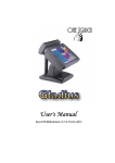
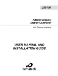
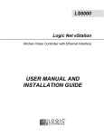
LM-3000 LCD MONITOR USER’S MANUAL SOME IMPORTANT NOTES FCC NOTICE This equipment generates, uses, and can radiate radio frequency energy and, if not installed and used in accordance with the instructions manual, may cause interference to radio communications. It has been tested and found to comply with limits for a Class A digital device pursuant to subpart J of Part 15 of FCC Rules, which are designed to provide reasonable protection against interference when operated in a commercial environment. Operation of this equipment in a residential area is likely to cause interference in which case the user at his own expense will be required to take whatever measures to correct the interference. WARRANTY LIMITS Warranty will terminate automatically when the machine is opened by any person other than the authorized technicians. The user should consult his/her dealer for the problem happened. Warranty voids if the user does not follow the instructions in application of this merchandise. The manufacturer is by no means responsible for any damage or hazard caused by improper application. ABOUT THIS MANUAL This manual assists the user to install and to utilize the LM-3000 which is a 12.1” high luminance LCD DSTN display system. The manufacturer of the LM-3000 heartily apologizes to the user for reserving the right to change or to modify this manual without notice due to the rapid and constant progress and improvement on science and technology. The user may always obtain the most up to date information through our web sites: http://www.mustekposiflex.com.tw Copyright Mustek Corp. 1997 All rights are strictly reserved. No part of this documentation may be reproduced, stored in a retrieval system, or transmitted in any form or by means, electronic, mechanical, photocopying, or otherwise, without the prior written consent from Mustek Corp. the publisher of this documentation. TRADE MARKS AND SERVICE MARKS POSIFLEX is a registered trademark of Mustek Corp.. Other brand and product names are trademarks and registered trademarks and service marks of their respective owners. I. OVERVIEW LM-3000 is a highly luminant with low shadow effect 12.1” LCD monitor. It is economical of pace and provides broad display area almost compatible to that of a 14” CRT monitor for PC application. II. PACKAGE CONTENTS • • • • LCD PANEL WITH CABLE INSTALLED VGA ADAPTOR CARD – PST032 DRIVER UTILITY THIS MANUAL III. LCD PANEL INSTALLATION The LM-3000 LCD panel is delivered with a separate base. The user has to find a surface which is horizontal and flat enough to place the LCD panel with its supporting base on. Please always manage to keep the installation site away from possibility of falling, shock, vibration, direct sun light, heavy dust, high temperature or high humidity etc.. The user should first take the pivot on the base out and insert the bottom part of the LCD panel into the opening of the base till it clicks. The user shall then fasten the pivot back to its position and the LCD panel is ready for cable connection. LM-3000 USER’S MANUAL - page 1 IV. DISPLAY ADAPTOR CARD INSTALLATION U4 U5 U6 U7 J2 U1 U3 U8 J1 U2 The attached PST032 is a PCI bus SVGA adaptor card which offers a 50 pin SCSI type connector for LM-3000 (Do not connect any device other than the LM-3000 LCD monitor to this port even if it was using a SCSI connector!) and a 3 x 5 D sub connector for external SVGA monitor. The user shall always first turn off the power to the PC and all its connected peripherals and disconnect all cables connected to the PC and then open the case of PC according to relevant instructions. The original VGA adaptor of the PC should be dismounted if there is one. Insert the PST032 into a proper PCI slot and restore everything else but the original VGA adaptor according to the instructions applicable to the PC. The PC will be ready for turning power on after the cable connections described below completed. LM-3000 USER’S MANUAL - page 2 V. CABLE CONNECTION Attention : Never connect the cable while power on! The cable length is 1.5 M, that allows the user to arrange the LM3000 at any place within this range from the PC. At one end of the cable attached is a SCSI 50 pin connector, at the other end, the connections are already installed to the rear of the LCD panel. Route the cables via the rear part of the base and clip them to the grooves to ensure that no excess strain passes to the cable connection to the panel. The user shall first press the two springs of the 50 pin SCSI type connector then connect the connector to the SVGA adaptor card and latch the connector. LM-3000 USER’S MANUAL - page 3 VI. UTILITY INSTALLATION A. For Windows 3.1 The drivers for Windows 3.1 are delivered in a separate 3.5” floppy diskette with the LCD monitor. To install the drivers for Windows 3.1 with the LCD monitor, the user should make sure that the Windows 3.1 is running properly using standard VGA driver. 1. 2. 3. 4. 5. 6. 7. 8. 9. 10. 11. 12. 13. 14. 15. 16. Select the MAIN group in Program Manager. Click on FILE or press ALT + F. Click on RUN or press R to select command line. Type in “A:\SETUP” with the diskette containing drivers for Windows 3.1 inserted in FDD A: (if it is in B: drive, type in “B:SETUP” instead), and then press ENTER. Choose for the language applicable. Press any key when being asked of confirmation to start installation. Press “ENTER” twice and then press the “END” key to input the directory to store drivers. Replace the command line “C:\WINDOWS” with the actual directory of the Windows files if they are not in the directory C:\WINDOWS. Then press ENTER. Press ESC key followed by Y key to finish the first stage of installation. To make the installed drivers effective, following procedures have to be taken out. Select MAIN group in Program Manager again. Select Windows Setup. Click on Options or press ALT + O. Click on Change System Settings or press C. Click on Display or press ALT + D. Select the intended video driver of proper resolution and colors then press ENTER. The names of the video drivers LM-3000 USER’S MANUAL - page 4 start with CHIPS followed by either the number 65550 or 6555X then followed by the matrix of resolution and colors. 17. Select Restart Windows to make the selected driver effective. B. For Windows 95 The following describes normal display driver installation procedures for Windows 95. Use these procedures when installing the display drivers provided in the directory for Windows 95. The drivers are stored in the subdirectory named WIN95 in the diskette. Click “Start”, then “Settings”, then “Control Panel”. Start the object "Display". Select the page of "Settings", and click the "Change Display Type" button. Choose the "Change" button in the "Adapter Type" area. Select the "Have Disk" button and press "OK". Specify the path to the new driver and press the <ENTER> key: Example 1: Insert the drivers disk in the A: floppy drive, and enter A:\WIN95. Example 2: Type in the name of the directory where you copied the drivers, either on your local hard drive or on a network share. Example 3: If you're not sure exactly where the drivers are, choose the "Browse..." button to find them. The "Select Device" dialog box will appear. Select the adapter that corresponds to the one you installed in your machine and click OK. Windows 95 will copy the display drivers to the proper directories on your system. Continue choosing Close until asked to restart your machine from the "Systems Settings Change" dialog box. After the system has restarted, you can go back into the Display applet and select alternate screen resolutions and color depths. LM-3000 USER’S MANUAL - page 5 C.For Windows NT 3.5x The drivers for Windows NT of versions 3.5x are stored in a subdirectory named NT35 in the diskette. 1. Run Windows NT Setup from Main Group 2. Choose Option from the menu (Alt-O) 3. Select Change system setting (Alt-C) 4. Choose "Other" under display section 5. Insert display driver disk in appropriate floppy drive D.For Windows NT 4.0 The drivers for Windows NT of versions 4.0 are stored in a subdirectory named NT40 in the diskette. Step 1: Install Windows NT as you normally would for a VGA display. First click the Start button, go to Settings and click on Control Panel. Choose the Display icon and click on the icon. In the Display Properties window, click on the Settings tab. Then click on Change Display Type. In the Change Display Type window, click on the Change button under Adapter Type. This will bring up the Select Device window. Step 2: In the Select Device window, click on the Other button. Enter source directory where the Windows NT driver files are located. Press <ENTER> and the name of the Chips and Technologies Video Accelerator driver will appear at the end of Models list box. Scroll to the end of the list box and double click on the driver. Once the installation is complete, the system must be shut down and restarted. LM-3000 USER’S MANUAL - page 6 Step 3: Upon restart, select the desired display settings from the Display property dialog box. Click on Test to test the newly selected graphics mode. A color test screen should appear, followed by the Testing Mode window. Click on Yes to continue. The Display Settings Change window will appear. Click on Restart Now for the new settings to take effect. VII. CONTROL AND ADJUSTMENT • Horizontal slide : The panel can be pushed left or right to slide without moving the base through a distance of 36 mm each side. • Swivel : The panel can be horizontally rotated, using the pivot on the base, 45° each way. • Tilt : The panel can be folded backward from the upstraight porition to nearly horizontal position, total range is 85°. • Brightness : On the rear side of the LCD display panel, there are two control knobs to control the picture displayed. The left one (as viewed from the rear side) marked as “ ” controls the brightness of the picture. Turning it clockwise as viewed from the rear side will increase the brightness of the picture, and turning it counter clockwise will decrease the brightness. • Contrast : The other one marked “ ” located to the right as viewed from the rear side controls the contrast of the picture. Turning it clockwise as viewed from the rear side will increase the contrast of the picture, and turning it counter clockwise will decrease the contrast. LM-3000 USER’S MANUAL - page 7 Tilt Brightness control knob Contrast control knob Swivel LM-3000 USER’S MANUAL - page 8 VIII.SPECIFICATION MODEL: Panel: Max. Resolution: Effective Display Area: Response Time: Backlight: Polarizer: Dot Size: Dot Pitch: Brightness: Operating Temperature: Storage Temperature: Operating Humidity: Storage Humidity: LM-3000 12.1 ” DSTN COLOR SVGA 800 x 600 247.02 (W) x 185.76 (H) mm 250 ms SIDE-EDGE TYPE CFL x 2 TUBES NON-GLARE TREATMENT 0.0821 (W) x 0.2863 (H) mm 0.2021 (W) x 0.3063 (H) mm 150 cd/m2 0°C ~ 40°C -20°C ~ 60°C 10% ~ 85%RH, non-condensation for Temp ≤ 40°C, 10% ~ 85%RH, noncondensation for Temp > 40°C, Absolute humidity shall be less than 85%RH at 40°C Back Light Reliability: 25,000 hrs Control Card (W/Power): PST032 Control Card Bus Type: PCI Video Memory Size: 1 MB Display Mode Supported: UP TO HIGH COLOR @ 800 x 600 Cable Length: 1.5m External Control: CONTRAST; BRIGHTNESS Swivel Range: Left 45° and right 45° Tilt Range: Stand straight (as 0°) to backward 85° Slide Range: Left 36 mm and right 36 mm Total Width: 300 mm Total Depth: 188 mm Total Height: 251 mm LM-3000 USER’S MANUAL - page 9 DISCLAIMER The manufacturer of the LCD display system makes no representations or warranties, either expressed or implied, by or with respect to anything in this manual, and shall not be liable for any implied warranties of fitness for a particular purpose or for any indirect, special or consequential damages. Information in this document is subject to change without notice and does not represent a commitment on behalf of the manufacturer. LM-3000 USER’S MANUAL - page 10