1
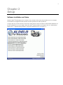
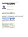
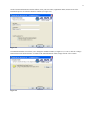
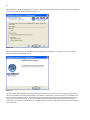
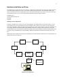
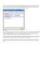
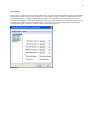
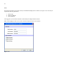
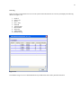
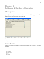
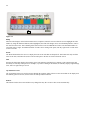
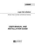
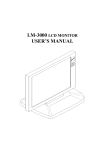
Aldelo® Kitchen Display Server
User Manual
2
PUBLISHED BY
Aldelo Systems Inc.
4641 Spyres Way, Suite 4
Modesto, CA 95356
Copyright © 1997-2007 by Aldelo Systems Inc.
All rights reserved. No Part of the contents of this book may be reproduced or transmitted in any form or by any means
whatsoever without the written permissions of the publisher.
Printed and Bound in the United States of America.
This manual is available through Aldelo Systems Inc. and resellers worldwide. For further information about other
languages that the manual may be translated into, please contact Aldelo Systems Inc. or visit our website at
www.aldelo.com. Send comments about this manual to [email protected]
Aldelo® is the registered trademark of Aldelo Systems Inc. Other products or company names mentioned herein may be the
trademarks of their respective owners.
The example companies, organizations, products, logos, people, places, and events depicted herein are fictitious. No
association with any real company, organization, product, logo, person, place, or event is intended or should be inferred.
3
PART 1 SETUP ___________________________________________________________ 5
Chapter 1 Requirements ___________________________________________________________________________ 7
Software Requirements ____________________________________________________________________________ 7
Hardware Requirements ___________________________________________________________________________ 7
Chapter 2 Setup __________________________________________________________________________________ 9
Software Installation and Setup _____________________________________________________________________ 9
Hardware Installation and Setup ____________________________________________________________________ 13
Planning System Configurations _________________________________________________________________ 13
Mounting LS3000 & LM3008E / LM3016E Units ___________________________________________________ 14
LS3000 Installation & Setup ____________________________________________________________________ 14
LS3000 Diagnostic Program_____________________________________________________________________ 14
LM3000E Series Installation & IP Setup ___________________________________________________________ 14
LEDs on Front Panel __________________________________________________________________________ 15
®
Aldelo Kitchen Display Server Setup Tab ___________________________________________________________ 17
Server Setup _________________________________________________________________________________ 18
Kitchen Monitors _____________________________________________________________________________ 19
Database Maintenance _________________________________________________________________________ 20
Order Routing ________________________________________________________________________________ 21
Users _______________________________________________________________________________________ 22
View Log ___________________________________________________________________________________ 23
PART 2 OPERATIONS ____________________________________________________ 25
Chapter 3 Software & Hardware Operation __________________________________________________________
Software Operation ______________________________________________________________________________
Hardware Operation _____________________________________________________________________________
Bump ______________________________________________________________________________________
Recall ______________________________________________________________________________________
Sum ________________________________________________________________________________________
Up and Down Arrows __________________________________________________________________________
Redraw _____________________________________________________________________________________
27
27
27
28
28
28
28
28
4
5
Part 1
Setup
6
7
Chapter 1
Requirements
Software Requirements
The Aldelo® Kitchen Display Server software drives the display of menu items and modifiers on each of the kitchen display
monitors. With the help of the Logic Controls ActiveX control, Aldelo Systems has developed an interface between
Aldelo® For Restaurants and the Logic Controls Logic Net system. The system communicates via TCP/IP between Aldelo®
For Restaurants and the Aldelo® Kitchen Display Server, as well as between the Aldelo® Kitchen Display Server and the
Logic Controls hardware.
You may install the Aldelo® Kitchen Display software on any computer on the network. However, the recommended place
to install it is on the server that holds the Aldelo® For Restaurants database. This computer is usually more powerful than
the rest. Installing it there also groups all databases together on the same system.
Hardware Requirements
Several devices make up the kitchen display system. The devices listed below are from the Logic Controls Logic Net
family of kitchen display hardware.
The LM3000 series control module unit is responsible for controlling communications between the Aldelo® Kitchen
Display Server and the I/O units that drive the monitors (see Figure 1-1). The Aldelo® Kitchen Display Server currently
supports the Ethernet version of the unit. An “E” at the end of the product number, for example “LM3008E” or
“LM3016E,” designates these units. The master control unit IP address can be configured using Telnet. HyperTerminal is a
good choice for a telnet client, and is available on most Windows systems.
Figure 1-1
8
The LS3000 I/O stations drive the monitors to display text (see Figure 1-2). Each monitor must be connected to an I/O
station. Each I/O station is assigned a station number. This number can be changed in the I/O station configuration when
the station first starts. Use the bump bar to change these settings.
Figure 1-2
The KB1700 series bump bars control moving or “bumping” orders, recalling orders, showing a summary of items, and
programming the I/O stations (see Figure 1-3). These units are configured using a utility from Logic Controls. The layouts
may be viewed at http://www.logiccontrols.com/web/prodKB17xtra.htm.
Figure 1-3
9
Chapter 2
Setup
Software Installation and Setup
Install the Aldelo® Kitchen Display Server software on any machine in the network, but preferably, the server computer.
The installation is straightforward and consistent with other products from Aldelo Systems Inc.
To begin, make sure you have the latest version of the Aldelo software. Insert the Aldelo® For Restaurants Installation CD
into the CD-ROM drive on your computer. When the Aldelo® Product Installer screen appears, click on “Aldelo Kitchen
Display Server – English Language Installer” to begin the installation process (see Figure 2-1).
Figure 2-1
10
When the InstallShield Wizard screen displays, click the “Next” button (see Figure 2-2).
Figure 2-2
The following screen displays the End-User License Agreement (“EULA” – see Figure 2-3). Read the EULA carefully.
Agreeing to the terms of the EULA creates a legal agreement between you and Aldelo Systems Inc. Accept the terms of the
agreement and click the “Next” button. You must agree to the terms of the EULA or you cannot proceed with the
installation.
Figure 2-3
11
On the Customer Information screen that follows, enter your User Name, Organization Name, and select one of the
installation options. Click the next button to continue (see Figure 2-4).
Figure 2-4
The Destination Folder screen allows you to change the installation folder (see Figure 2-5). To do so, click the “Change”
button and select the desired location. To install to the default destination folder, simply click the “Next” button.
Figure 2-5
12
When the Ready to Install the Program screen displays, check the Current Settings window to make sure all the information
is correct, then click the “Install” button (see Figure 2-6).
Figure 2-6
When the installation finishes, the InstallShield Wizard Completed screen displays (see Figure 2-7). Click the “Finish”
button to complete the installation process.
Figure 2-7
Once the Aldelo® Kitchen Display Server is installed, launch the software for the first time. The software prompts you to
enter the serial number that came with the product. This number is found on the case that the Aldelo® For Restaurants CD
came in. When you enter this number, the software prompts for activation. The Aldelo Systems Support Department can
assist you in activating the software. To get started with the application immediately, simply ignore the messages and
activate later. The software will shutdown every 30 minutes until you activate it. This allows you to activate the software at
your convenience.
13
Hardware Installation and Setup
The LM3000 Series control units come in two interface configurations; serial interface only and serial / Ethernet interfaces.
The Aldelo® Kitchen Display Server only works with the models that support Ethernet. The LM3008E includes eight
LED’s to show the status of up to eight kitchen systems. The LM3016E includes sixteen LED’s to show the status of up to
sixteen kitchen systems. The “E” in the model number designates that the unit supports Ethernet.
LM3000E Series
(Serial and Ethernet Interface)
LM3008E
LM3016E
Planning System Configurations
The proper configuration for Logic Net is a loop. The total RS485 cable length cannot exceed 1220 m (4000 ft.). CAT5
cable should be used. The loop configuration provides redundancy and is therefore more reliable. A loop configuration
starts with an LM3008E / LM3016E, with an LS3000 attached to it. Another LS3000 attaches to the previous LS3000, and
so on, ending with the last LS3000 attached to the LM3008E / LM3016E. A break in a cable between any two devices
would break the loop, but communication would still be possible between the LM3008E / LM3016E and all LS3000s. This
is possible because both RS485 ports on the LM3008E / LM3016E communicate information from the host at the same
time.
Note: Simple chain configurations starting from each RS485 port on the LM3008E / LM3016E are not recommended. The
connections must be in a loop form.
LS3000
LS3000
LS3000
LS3000
LS3000
LM3008E/
LM3016E
Ethernet
Switch
Aldelo
KDS
Sample Loop Configuration
LS3000
Ethernet Port
on
LM3008/16E
14
Mounting LS3000 & LM3008E / LM3016E Units
Mounting brackets are provided to facilitate mounting the LS3000 and the LM3008E / LM3016E to a wall. The installer
should use wall anchors that have the capacity to support 4.3 kg (9.5 lb.). Wall anchors that specify weight capacity are
available commercially.
LS3000 Installation & Setup
Make sure that power to all equipment is turned off before making your connections. Making connections while power is
on may cause damage to the system. A keyboard or bump bar is required for the LS3000 setup. After placing the system
components and cabling, setup each LS3000 using the following procedure.
1.
2.
3.
4.
5.
6.
7.
8.
Attach the monitor, keyboard or bump bar, power supply, and any optional RS232 device to the LS3000.
Plug the monitor and the LS3000 power supply into an AC power source with surge protection and turn on the
power to the monitor.
Reset the LS3000 by pressing the reset button on the front panel with a pointed device (such as a paper clip).
After pressing the reset button, within 5 seconds, press the up or down arrow on the keyboard or bump bar to
navigate to the setup menu.
Verify that the values in the banner message box at the top of the screen for RAM Test and E2PROM Status are
OK. If the values are other than OK, repeat steps three and four. If this fails to resolve the problem, replace the
LS3000 unit.
Setup the Logic Station Address as follows:
a. Select Address Setup from the menu using the up or down arrow keys. Press ENTER to open the input
area.
b. Enter the assigned, unique, 2-digit Logic Station Address in the range between 00 and 15, inclusive.
c. Press ENTER to accept.
d. Verify that the address you entered appears at the top left in the banner message box.
Press the CTRL key to exit the LS3000 setup menu.
Setup is now complete for the LS3000. Repeat the procedure above for each LS3000 unit in the system. Be sure to
use a unique address for each LS3000. Always verify your input in the banner message box at the top of the panel.
LS3000 Diagnostic Program
Each time the LS3000 power is turned on, the device runs a ROM-based setup and diagnostic program that is used to set
system parameters and generate problem determination information. Run the program by pressing the system RESET
button. As soon as the diagnostic menu appears, quickly press the up arrow or the down arrow keys on the keyboard to
highlight the required function. Press ENTER to select the function. After the setting or test is complete, exit by pressing
the CTRL key.
LM3000E Series Installation & IP Setup
Make sure that power for all equipment is off before making connections. Making connections while power is on may
cause damage to the system.
1.
2.
3.
4.
5.
The LM3008E / LM3016E Ethernet port must be connected to the server computer via an Ethernet switch.
Connect the LM3008E / LM3016E to the network of LS3000 units via the RS485 cable loop. The connections
must be in a loop form with Cat 5 cable.
Connect at least one LS3000 unit (with VGA display connected) to the LM3008E / LM3016E and connect the
LM3008E / LM3016E to the Ethernet LAN. Turn on the power to the LS3000 unit. When power is turned on to
the LM3008E / LM3016E, the current IP address and port number display on the LS3000 unit’s VGA display.
Record the original PC IP address, then set the computer’s IP address to same IP group as the LM3008E /
LM3016E current IP shown on the LS3000 VGA screen (the first 3 numbers of the IP address must match
exactly). Refer to the procedures outlined in the operating systems’ manual for setting the computer’s IP address.
Run the Telnet program on the server PC with connection to LAN. For Windows, under the command prompt,
enter “Telnet <IP address>,” where <IP address> is the current IP of the LM3008E / LM3016E displayed on the
LS3000’s VGA screen. (Note: Telnet is not available in Windows Vista.)
6.
7.
8.
15
Enter command “1” along with the new IP address as the parameter to enter the new IP address for the unit. For
example, enter “1 192.168.100.10” to change the IP address to “192.168.100.10.” (Note: set the IP address to the
same original IP group of your network. You may need to check with your network administrator for a free IP
address).
Check that the “Current Configuration” shows the required IP address. If necessary, change the IP address again
with command “1.” Then, enter command “4” to save the settings. To cancel the IP changes made in this session,
enter command “0” to quit without saving.
Set the server PC back to the original network IP address recorded in step 2.
After the IP address has been changed, the LM3008E / LM3016E runs with the new IP address automatically. The new IP
address displays on the LS3000’s VGA monitor.
If Telnet shows double characters when entering commands & parameters, local echo is set to on. To eliminate the double
characters, set local echo to off. (Enter “Telnet” in command prompt to start Telnet and enter the command “unset
local_echo” for Windows 2000 or “unset localecho” for Windows XP. Enter “quit” to exit Telnet.)
Note:
Simple chain configurations starting from each RS485 port on the LM3000E are not recommended. The connections must
be in a loop form.
LEDs on Front Panel
The eight LEDs on the front panel of LM3008E indicate the status of LS3000 units from addresses 0 to 7. If more than
eight stations are required, model LM3016E is available with sixteen LEDs. When the LED is off, the corresponding
LS3000 unit is offline. When the LED is on or blinking, the corresponding LS3000 unit is online. Check the connections if
any active LS3000 unit is not showing the correct LED status. One or more LEDs blinking indicates a cable break or loose
connection. While the system still works with all online stations under this single cable fault condition, the blinking LEDs
alert you to a cable connection failure that must be remedied. The location of the cable break can be easily identified. The
group of blinking LEDs shows that the corresponding segment of the network is disconnected from the portion of the
network displaying the LEDs that are on steadily.
16
When the Aldelo® Kitchen Display Server starts, the main page displays the current statistics for the system on which the
software is running (see Figure 2-8). The information displayed is the “Kitchen Display Server IP/Port,” which is the IP
address and port number of system currently running the Aldelo® Kitchen Display Server and the “Kitchen Control Unit
IP/Port,” which is the current setting for where to look for the LM3008E / LM3016E.
Figure 2-8
Record the value displayed in the Kitchen Display Server IP/Port field. Open Aldelo® For Restaurants and navigate to Back
Office > Store Settings > Other. Scroll down to the bottom of the Additional Options list. Enter the IP address recorded
previously into the Setting Value column of the Aldelo® Kitchen Display Server IP Address field. Next, enter the port
number into the Setting Value column of the Aldelo® Kitchen Display Server IP Port field.
For example, with the value listed for the Kitchen Display Server IP/Port field in Figure 2-8 above, enter “172.28.18.5” in
the Aldelo® Kitchen Display Server IP Address field and “1989” in the Aldelo® Kitchen Display Server IP Port field. When
complete, click the “Save” and “Done” buttons to save the changes and exit the Back Office.
The Connected Clients field displays the Aldelo® For Restaurants systems currently connected to the Aldelo® Kitchen
Display Server software. The IP address and port number of each system displays. As each system connects, it is added to
the list.
17
Aldelo® Kitchen Display Server Setup Tab
The following sections refer to the buttons found on the Setup tab of the Aldelo® Kitchen Display Server software (see
Figure 2-9).
Figure 2-9
18
Server Setup
To setup the Aldelo® Kitchen Display Server to connect to the LM3008E / LM3016E, setup the IP address of the LM3008E
/ LM3016E, as discussed previously in the section “LM3000E Series Installation & IP Setup.” Once you have the IP
Address set correctly in the LM3008E / LM3016E, fill in the “Server Setup” settings under the Setup tab in the Aldelo®
Kitchen Display Server (see Figure 2-10). Update both the “Control Unit IP Address” and the “Control Unit IP Port” to
match the configuration of the LM3008E / LM3016E.
You may also change the port number on which the Aldelo® Kitchen Display Server communicates with Aldelo® For
Restaurants. This is done in the “Server IP Port” field. If you change this port, you must also change the port number
configuration in Aldelo® For Restaurants.
Figure 2-10
19
Kitchen Monitors
On the Kitchen Monitors screen, a list of kitchen monitor appears on the left side (see Figure 2-11). For each monitor in the
list, you can customize the colors that represent each item listed. The “Orders Shown” drop down list allows the user to
choose whether to display, two, four, or eight orders per monitor. The default number is eight.
The “Preparation Time limit/Mins” field allows the user to choose the number of minutes allowed to elapse before a
displayed order begins flashing because it has taken too long to complete.
Figure 2-11
20
Database Maintenance
There are two options in the Database Maintenance screen: “Purge Database” and “Backup Database” (see Figure 2-12).
The Purge Database button allows you to delete old transactions in the database when they are no longer needed. These are
transactions that have already been completed and no longer need to be tracked. The Backup Database button creates a
copy of your current database and prompts you choose a location for storing the file.
Figure 2-12
21
Order Routing
On this screen, you direct the flow of menu items and orders to the correct monitors depending on the type of order and the
kitchen printer to which the order prints (see Figure 2-13). For example, in Figure 2-13 below, if a Dine In menu item is
sent to Kitchen Printer 1, it displays on Kitchen Monitor 00 (the sixteen monitors are numbered from 00 to 15). This
location may be changed by expanding the drop-down list and selecting the desired monitor. Each different order type may
be displayed on a different monitor in the same manner. You may also elect to show the table number, station number,
ticket, and order type by selecting the checkboxes below the drop-down list boxes.
Figure 2-13
22
Users
The Users screen allows you to create security for the Kitchen Display Server software (see Figure 2-14). Users may be
assigned the following permissions:
1.
2.
3.
Allow Setup
Allow View Report
Allow Shutdown
Once logged in, you can lock the interface so that nobody can tamper with the software.
Note: When logging in with a user account, usernames and passwords are case sensitive.
Figure 2-14
23
View Log
This screen shows each transaction as it sent to the system. Each transaction has its own entry and displays the following
details (see Figure 2-15):
1.
2.
3.
4.
5.
6.
7.
8.
9.
10.
Printer #
Order Type
Server
Date / Time
Order ID
TransactionID
Menu ItemID
Short Note
Table Number
Modifier String
Figure 2-15
The modifier string is a series of information about any modifiers that came with a particular menu item.
24
25
Part 2
Operations
26
27
Chapter 3
Software & Hardware Operation
Software Operation
When you place orders in Aldelo® For Restaurants, the items you send to the kitchen display on the monitors. There is an
option to expedite the sending of items to the kitchen with the “Print Kitchen / Bar Items on the Fly” option in Aldelo® For
Restaurants. To set this up, navigate to Back Office > Store Settings > Print > Kitchen / Bar. Select the “Print Kitchen /
Bar Item On the Fly” checkbox to enable this option (see Figure 3-1).
Figure 3-1
Voids are handled as usual in Aldelo® For Restaurants. When you void an order, the order is removed from the screen. If
you void just one item, the item is removed from the screen.
Hardware Operation
The buttons on the KB1700 option A are used to provide functionality for managing orders (see Figure 3-2). These buttons
are as follows:
1.
2.
3.
4.
5.
6.
7.
8.
Bump
Recall
Sum
Page (not used)
Up Arrow
Down Arrow
0–9
Redraw
28
Bump
Recall
Sum
Page
(not used)
Up
Arrow
Down
Arrow
Redraw
0-9
Figure 3-2
Bump
When an order displays on the kitchen monitor and is completed, it must be removed from the screen. Highlight the order
number by using the numbered buttons (when highlighted, the order title changes color). Press the Bump button to remove
the order from the screen. This remaining orders shift to allow room for additional new orders. The maximum number of
accessible orders is eight. An unlimited number of orders can be waiting in the queue, but only eight can be viewed on the
screen at one time.
Recall
The Recall button allows the user to re-display the most recent order that was bumped off. This button will only recall the
most recent order, and cannot be used to recall an order prior to the last one removed from the screen.
Sum
Pressing the Sum button displays the summary panel. The summary panel displays a summary of all common items and
how many are currently in the queue. For example, if you have a hotdog on each order, the summary displays eight hotdogs
since, there are eight orders per screen.
Up and Down Arrows
The Up and Down arrows are used to navigate through the summary panel. If there are more items than can be displayed in
the summary panel at one time, use the arrows to scroll up and down the list.
Redraw
This button refreshes the screen and shows any changes that may have occurred. This occurs automatically.
29
A
Activation ..................................................................... 12
Address Setup ............................................................... 14
®
Aldelo Kitchen Display Server Setup Tab .................. 17
Allow Setup .................................................................. 22
Allow Shutdown ........................................................... 22
Allow View Report ....................................................... 22
B
Backup Database .......................................................... 20
Banner Message Box .................................................... 14
Banner Message Box .................................................... 14
Bump ............................................................................ 28
Bump Bar...................................................................... 14
Bump Bar.................................................................. 8, 14
C
CAT5 Cable .................................................................. 13
Connected Clients Field ................................................ 16
Control Unit IP Address ............................................... 18
Control Unit IP Port ...................................................... 18
Customer Information Screen ....................................... 11
D
Database Maintenance .................................................. 20
Destination Folder Screen............................................. 11
E
E2PROM Status ............................................................ 14
End-User License Agreement ....................................... 10
Ethernet......................................................................... 13
EULA ........................................................................... 10
H
Hardware Installation and Setup ................................... 13
Hardware Operation ..................................................... 27
Hardware Requirements ................................................. 7
HyperTerminal ............................................................... 7
I
InstallShield Wizard ............................................... 10, 12
K
KB1700 Series Bump Bar .............................................. 8
Keyboard ...................................................................... 14
Kitchen Control Unit IP/Port ........................................ 16
Kitchen Display Server IP/Port .................................... 16
Kitchen Monitors .......................................................... 19
L
LEDs on Front Panel .................................................... 15
LM3000 Series ......................................................... 7, 13
LM3000E Series Installation & IP Setup ..................... 14
LM3008E ...........................................7, 13, 14, 15, 16, 18
LM3016E ...........................................7, 13, 14, 15, 16, 18
Local Echo .................................................................... 15
Logic Controls ActiveX Control .................................... 7
Logic Station Address ................................................... 14
LS3000 .......................................................... 8, 13, 14, 15
LS3000 Diagnostic Program ......................................... 14
LS3000 Installation & Setup ......................................... 14
M
Mounting LS3000 & LM3008E / LM3016E Units ....... 14
O
Option A ....................................................................... 27
Order Routing ............................................................... 21
P
Permissions ................................................................... 22
Planning System Configurations ................................... 13
Preparation Time limit/Mins ......................................... 19
Print Kitchen / Bar Items on the Fly ............................. 27
Purge Database ............................................................. 20
R
RAM Test ..................................................................... 14
Ready to Install the Program Screen ............................. 12
Recall ............................................................................ 28
Redraw .......................................................................... 28
Reset Button .................................................................. 14
Reset Button .................................................................. 14
RS485 ............................................................... 13, 14, 15
RS485 cable .................................................................. 14
S
Sample Loop Configuration ....................................... 13
Security ......................................................................... 22
Serial Number ............................................................... 12
Server IP Port ................................................................ 18
Server Setup .................................................................. 18
Setup Tab ...................................................................... 17
Software Installation and Setup ...................................... 9
Software Operation ....................................................... 27
Software Requirements ................................................... 7
Sum ............................................................................... 28
T
Telnet .................................................................. 7, 14, 15
U
Up and Down Arrows ................................................... 28
Users ............................................................................. 22
V
View Log ...................................................................... 23
Voids ............................................................................. 27
W
Wall Anchors ................................................................ 14
Windows 2000 .............................................................. 15
Windows Vista .............................................................. 14
Windows XP ................................................................. 15
30