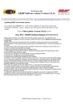
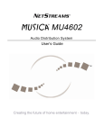
1
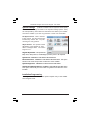
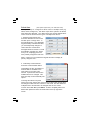
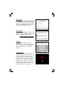
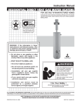
NAVIGATOR
ELK PRODUCTS M1
USER GUIDE
Elk-M1KPNAV
Touchscreen Keypad
L635 Rev. A 8/16/12
M1KPNAV Navigator Touchscreen Keypad - User Guide
Introduction
Congratulations on purchasing a Navigator Keypad as part of your featured packed
M1 Security and Automation controller.
Navigator is a stylish Touch Screen Keypad interface for use with the M1 series
Cross Platform Controllers. It features a large touch sensitive 3.5" color LCD with
bright, easy to use graphic icons and softkeys. Navigator makes the M1 Security
and Automation system extremely easy to operate.
This User Guide Manual is provided to help aquaint you with the operation of the
Navigator Touchscreen Keypad so that you may become proficient with its
operation. Full operation of your M1 Control may also require that you read and
follow the regular M1 User Guide that was furnished with the M1 Control.
ALL USERS SHOULD READ AND FOLLOW THE INSTRUCTIONS AND CAUTIONS
CONTAINED IN THIS MANUAL. FAILURE TO DO SO COULD RESULT IN THE SYSTEM
NOT WORKING PROPERLY. KEEP THIS MANUAL IN AN EASY TO ACCESS
LOCATION. READ AND FOLLOW ALL INSTRUCTIONS CAREFULLY. IF YOU DO
NOT UNDERSTAND ANY PORTION OF THIS MANUAL OR IF YOU HAVE ANY
QUESTIONS ABOUT YOUR SYSTEM, CONTACT THE INSTALLING COMPANY FOR
ADDITIONAL ASSISTANCE.
PLEASE BE AWARE OF THE FOLLOWING:
The level of security obtained is directly related to two major factors.
1. The quantity, quality, and placement of sensors attached to this system.
2. The knowledge and operating skills that you have of the system, including but not
limited to the weekly testing of the complete system.
Important notes when preparing a security/safety plan for your home or business:
1. This system is an electronic device and is subject to failure or malfunction. You
should not rely on it as your single source of security.
2. This system will not work without power.
3. This system should be tested weekly.
4. Audible warning devices will need to be loud enough, wired correctly, and properly
placed to provide adequate notification of an alarm event.
5. Smoke and heat detectors may not detect smoke and heat in all situations.
6. Only qualified security professionals should install and maintain this system.
7. It may be possible to arm this system WITHOUT the backup battery connected or
with less than an adequate charge. Weekly testing of the system with AC Power
removed should be performed to verify that the battery is connected and
adequately charged.
8. Care should be taken after testing to make certain that AC Power is restored.
The National Fire Protection Association publishes a standard for household fire
warning equipment. N.F.P.A. #72. Further Information can be obtained by contacting;
NEPA Public Affairs Dept., Batterymarch Park. Quincy, MA 02269.
Page 2
M1KPNAV Navigator Touchscreen Keypad - User Guide
TABLE OF CONTENTS
Main Screen .................................................................................................... 4
Status Window ...................................................................................................... 4
View Violated Zones ........................................................................................... 5
EXIT - Arming in the “Away” Mode .................................................................. 5
EXIT - Arming in the “Vacation” Mode ............................................................. 5
STAY - Arming in the “Stay” Mode ................................................................... 6
F Keys - Special Function Keys ......................................................................... 6
Display “Show” F Keys ........................................................................................ 7
BYPASS - Excluding Zone(s) ............................................................................... 7
CHIME - Annunciating Zone Activations .......................................................... 7
Disarming and Resetting the System ............................................................. 7
Acknowledging an Alarm ................................................................................... 8
Troubles ................................................................................................................. 8
Main Menu Screen .......................................................................................... 9
Automation .......................................................................................................... 10
Reset Smoke Detectors ................................................................................... 18
Walk Test Area .................................................................................................... 18
History Log .......................................................................................................... 19
Zone Status ......................................................................................................... 19
Change User Codes .......................................................................................... 20
System Settings ................................................................................................. 21
Installation Programming ................................................................................ 21
Select Area .......................................................................................................... 22
Synchronise ........................................................................................................ 23
Clean Screen ....................................................................................................... 23
Authorise ............................................................................................................. 23
Keypad Locked ................................................................................................... 23
Fire Safety & Maintenance ........................................................................... 24
Silencing a Fire Alarm ....................................................................................... 24
Resetting Smoke Detectors ............................................................................ 24
Acknowledge/Reset an Alarm ........................................................................ 24
Household Fire Safety Audit ............................................................................ 24
Emergency Evacuation Plans ...................................................................... 25
System Testing ............................................................................................. 26
FCC Compliance Statement ......................................................................... 26
Navigator Protective Screen Film ................................................................ 27
Page 3
M1KPNAV Navigator Touchscreen Keypad - User Guide
Main Screen
The top line of the Main screen displays the current time and date from the
M1 Control. Actual display may vary slightly from that shown.
Status Window
A Status Window directly beneath the time and date includes an Icon which
will be either green, yellow, or red, depending on the M1’s status.
A text description of the current status appears on the top line.
The bottom line of text alternates between displaying keypad area, current
trouble and/or custom message.
When the M1 status is “Not Ready” or “Ready Force” the total number of
violated zones will be displayed on the right side of the status window.
Page 4
M1KPNAV Navigator Touchscreen Keypad - User Guide
View Violated Zones
To view zones that are violated (not ready) press the button labeled “Violated
Zones” on the top right corner of the button arrangement. The display will
begin with the first violated zone. The Up and Down buttons that appear in
the Status Window can be used to move between zones.
The Main Screen contains a numeric entry keypad along with several
feature buttons, some of which are not found on other Elk M1 Keypads.
EXIT - Arming in the “Away” Mode
Away mode arming is the highest arm level, intended for use when the
premises is unoccupied. Both perimeter and interior zones will be armed.
The Ready to Arm or Ready to Force Arm must be present for the alarm to
be armed.
1. Enter a User code or press Exit (Quick Arm must enable by Installer).
2. Display will change to Armed Away.
The exit tone will begin to countdown.
4. Leave the premises immediately while the exit delay is active.
5. At the end of the exit delay the system will be fully armed Away.
During the final 10 seconds of the exit delay the exit tone will beep faster,
warning that time is nearly expired. If you feel that you will NOT be able to get
out and close the exit door within the remaining time it is recommended that
you start over by returning to the keypad, disarm the system, and arm again.
EXIT - Arming in the “Vacation” Mode
Vacation mode is a second level of Away mode and is primarily useful to
activate energy saving automation features when the building is not occupied for an extended time. After arming, press the EXIT button again to
change the armed mode to vacation.
Page 5
M1KPNAV Navigator Touchscreen Keypad - User Guide
STAY - Arming in the “Stay” Mode
Stay mode arming is used when the premises is occupied. All perimeter
doors and windows are armed, and all interior zones are excluded.
1.
2.
3.
Enter a User code or press the STAY key (Quickarm). **
Display will change to Armed Stay. Exit tone is silent during Stay arming.
All interior zones will be excluded in the Stay mode.
Exit and Entry zones will still have their respective delay times.
** Additional presses of the Stay key (while the exit delay is still active) may be
allowed to switch to alternate modes of Stay. In some instances this may be
allowed even while the system is armed.
Armed Stay Instant = Deletes the Entry Delay on entry/exit zones.
Armed Night = Adds protective zones designated as Night Zones.
Armed Night Instant = Adds the Night zones AND deletes Entry Delay.
** Auto Stay Arming
There is an option which allows the system to automatically switch from Away
mode to Stay mode when no perimeter delayed doors are opened during the exit
delay countdown time. Essentially, this auto stay option makes sure the alarm is
armed in the stay mode if there is no detection of anyone leaving the building.
** These options must be enabled by the Installer.
F Keys - Special Function Keys
There are 6 special function “F” keys which your Installer may enable for
purposes as emergency panic alarm, automation event triggers (lights,
outputs), and more. F1 and F2 are on the Main screen. Pressing “Display
F=Keys” will present all 6 “F” keys together on an extended main screen.
Each individual key may be programmed to allow activation via a single
press, or to require double press (2 quick presses in a row). Double press
helps prevent accidental activation. If a key is set to require double press
the screen will display “Press F_ Again To Activate” immediately after the
first press. This times out after ~8 seconds if no 2nd press occurs.
F1 FIRE - If enabled by the Installer this key will trip a fire alarm panic. An
Alarm Monitoring center can be contacted if you subscribed to monitoring.
F2 POLICE - If enabled by the Installer this key will trip a police panic alarm.
The Installer can enable this to either be silent or audible. An Alarm
Monitoring center can also be contacted IF you subscribed to monitoring.
Page 6
M1KPNAV Navigator Touchscreen Keypad - User Guide
Display “Show” F Keys
Pressing this button will swap the display to the extended Main screen. All 6
of the “F” keys are available on this screen.
BYPASS - Excluding Zone(s)
Bypass permits zones to be excluded (ignored) by the control during the
current armed period. Bypassed zones cannot trip an alarm. Bypasses on
zones are automatically canceled when the control is disarmed.
1. Press the Bypass key PLUS the number of the zone to be bypassed.
2. Press the Bypass key again.
3. The display will indicate whenever one or more zones are bypassed.
Note: Only zones programmed as bypassable may be bypassed.
Bypassing may also require entry of a user code.
CHIME - Annunciating Zone Activations
Chime produces an audible alert when selected doors, windows, or other
zones are opened (violated). This is ideal for annunciating when someone
enters or leaves the premises through a normal doorway, but it may also be
used to annunciate abnormal access to restricted areas.
There are 4 selections or levels of Chime: Tone, Voice, Tone/Voice, and Off.
1. Press the Chime key one time to select the Chime Tone mode.
2. Press again within ~30 seconds to select Chime Voice mode.
3. Press again within ~30 seconds to select Chime Tone/Voice mode.
4. Pressing again within ~30 seconds will turn Chime mode Off.
Note: Only the installer has the ability to program which doors, windows,
etc. (zones) will be included in the Chime mode.
Disarming and Resetting the System
When you enter the premises through one of the Entry delayed zones the
system should sound a continuous entry delay tone and display a count
down of the entry delay time.
1. Proceed directly to the keypad and enter a valid user code.
2. The entry delay tone should stop and the system will be disarmed.
Page 7
M1KPNAV Navigator Touchscreen Keypad - User Guide
What to do if the Alarm is Sounding
1.
2.
3.
4.
Proceed directly to the Keypad and enter your user code.
The alarm and/or keypad tone should silence.
The System Armed display should disappear.
If the alarm was accidental, contact the Central Monitoring Center to
avoid a false dispatch of the authorities.
Note: False alarms often occur when someone enters the building and
doesn’t enter their User Code prior to the entry delay time expiring. The
display shows the alarm type and first zone that tripped.
Acknowledging an Alarm
After an alarm has been silenced by a valid user code, the display will
continue to show the alarm type and zone until the Clear key is pressed or
until a valid user code is entered a second time. This “Acknowledgment” is
so that the user sees what caused the alarm after things are quieted.
To acknowledge the alarm and reset the system:
1. Press the Clear key or enter your user code again.
2. The alarm/condition will clear from the keypad display.
Troubles
There are numerous trouble conditions which the system may display:
AC Power Failure
Low Backup Battery
Telephone Line Fault
Fire Alarm Trouble
Missing Keypad, Expander (Zone or Output)
Communications Fail
Troubles are annunciated by an intermittent beeping from the keypad and a
display of the Trouble condition(s). The beeping may be silenced by
pressing the Clear key but the trouble must be acknowledged before other
keypad operation may continue.
1. To acknowledge a trouble condition enter a user code.
2. Until the trouble condition is resolved, the keypad will momentarily
flash the condition along with the normal keypad information. If a new
Trouble should occur, the keypad beeping will resume.
Page 8
M1KPNAV Navigator Touchscreen Keypad - User Guide
Main Menu Screen
The Main Menu screen will be displayed when the Menu button is pressed
on the Main screen. Various system User and Installer options are available.
The Main Menu is split across 2
pages.
To move between the pages press
“Next Page” or “Previous Page”.
An Information button at the bottom
of both menu pages provides
contact informaton for your
Installation Company. This page
must be filled in by the Installer.
To return to the main screen press the EXIT MENU button or press the red
close button on the top right of the screen.
Page 9
M1KPNAV Navigator Touchscreen Keypad - User Guide
Automation
The M1 system has six (6) categories of Automation options which may
be controlled via the Automation button. Your system may or may not be
configured with these options. When the “Automation button” is pressed
the screen will display the following options:
·
Tasks
·
Lighting
·
Outputs
·
Temperature Sensor
·
Keypad Temperature
·
Thermostat Temperature
·
Automation Custom Settings
To return to the Main Menu press the Menu button. To return completely
back to the Main screen press the red close button on the top right of the
screen.
Page 10
M1KPNAV Navigator Touchscreen Keypad - User Guide
Automation - Task Activation
A Task is an M1 feature that is similar in operation to a “macro” found in a
word processor or spreadsheet program. It allows a series of automation
steps or processes to be activated by a single button press. Each task may
have a name such as: Water the Lawn (to turn on electric water valves),
Welcome Home (to turn on a series of Lights or adjust the temperature).
The Navigator Task Activation screen can display up to 8 task buttons at one
time. Each task button displays the task number with or without a name.
A scroll bar along the right side as well at the Previous and Next buttons
may be used to move around to additional pages of tasks.
A single press of a task button is all that is required to activate that task. The
button will momentarily light up when touched, however the task buttons
will never be illuminated when viewed. This is due to the fact that a task
does not have a state of On or Off, only momentary.
NOTE: The installer may have tagged a task to “not show” on the Task
Activation screen. In reality the task button will still be shown on the screen,
but will be greyed out to indicate that it cannot be manually activated. These
would typically be used for special internal functions.
To return to the Main Menu press the Menu button. To return completely
back to the Main screen press the red close button on the top right of the
screen.
Page 11
M1KPNAV Navigator Touchscreen Keypad - User Guide
Automation - Task Activation - Single View
At the bottom of the Task Activation screen is a “Single View” button. This
provides a means to locate and activate a single Task, including a Task
which has been greyed out or “hidden” on the regular screen. This button
is mainly intended for use by advanced users that understand the reason a
Task may be hidden, and understand the consequences that may be
involved when activating a hidden task.
Press the “Single View” button to display the Single View Tasks screen.
Press the Next or Previous buttons to scroll through a list of all available
Tasks. You may also directly choose a Task by entering its two digit number
(if known). NOTE: Direct number entry is the only way to gain access to a
hidden task. The Next and Previous buttons skip over hidden Tasks.
Press the Activate Task button when you locate the desired task.
To return to the previous screen press “Multi View.”
To return to the Main Menu press the Menu button. To return completely
back to the Main screen press the red close button on the top right of the
screen.
Page 12
M1KPNAV Navigator Touchscreen Keypad - User Guide
Automation - Lighting Control
This menu option allows access to view and control any intelligent lighting
devices which may be integrated with your M1 system.
The Lighting Control screen can
display up to 4 lights at one time.
A scroll bar along the right side will
scroll to 4 more lights, as can the
Previous and Next buttons.
Each Light has a number, a name,
and a Icon showing the current state.
The current status is also shown by
text with: ON, OFF, or Dim % (if the
light is dimmable).
Some lights may be intentionally hidden. These are generally programmed
by the installer for applications not necessarily needed from the keypad.
These lights will be greyed out to prevent accidental activation.
To return to the Main Menu press the Menu button. To return completely
back to the Main screen press the red close button on the top right of the
screen.
Automation - Lighting Control - Single View
At the bottom of the Lighting Control screen is a “Single View” button.
This provides a means to locate and
control any light, even one that has
been greyed out or “hidden” on the
regular Lighting screen.
Press “Single View” and then use the
Next or Previous buttons to scroll
through a list of available Lights. You
may also directly choose a Light by
entering its two digit number (if known).
Page 13
M1KPNAV Navigator Touchscreen Keypad - User Guide
NOTE: Direct number entry is the only way to gain access to to a hidden
Light. The Next and Previous buttons skip over hidden Lights.
In Single View the lighting state can be toggled using the “Change State”
button. ie Turn lighting ON or OFF.
If the Light is dimmable then a Dim button will be displayed. Press the Dim
button will display the Lighting Control Dim screen.
To return to the regular Light screen press “Multi View”.
To return to the Main Menu press the Menu button.
To return completely back to the Main screen press the red close button on
the top right of the screen.
Automation - Lighting Control - Lighting Dim
Pressing DIM will present the following screen.
The lighting number, lighting name,
and current dim level (if known) is
displayed at the top of the screen.
The lighting dim level may be changed
by pressing one of the lighting dim
percentage buttons. The button
corresponding to the current dim value
will be highlighted.
To return to the regular Light screen
press “Back”. To return completely back
to the Main screen press the red close button on the top right of the screen.
Note: Lighting devices may take a little longer to display than Tasks or Outputs since
Navigator must retrieve the status of each one from the M1 panel.
Page 14
M1KPNAV Navigator Touchscreen Keypad - User Guide
Automation - Output Control
This option allows access to control any outputs that may be configured
with your system. Outputs are relays or voltage trips used for controlling
other types of equipment.
Up to 8 outputs may be displayed on
the screen at one time with the Output
number and name.
A scroll bar on the right side will scroll
to other pages of outputs, as can the
Previous and Next buttons.
A single press of an output button will
change the state of the output.
Some outputs may be intentionally
hidden. These are generally setup
by the Installer for applications not necessarily needed from the keypad.
These outputs will be greyed out to prevent accidental activation.
To return to the Main Menu press the Menu button. To return completely
back to the Main screen press the red close button on the top right of the
screen.
Automation - Output Control - Single View
At the bottom of the Output Control screen is a “Single View” button. This
provides a way to navigate directly to any output, even one that has been
greyed our or “hidden” on the regular Output Control screen.
Press the “Single View” button for the
single view Outputs screen.
Press the Next or Previous buttons to
scroll through a list of available
Outputs. You may also directly choose
a Output by entering its two digit number
(if known).
Page 15
M1KPNAV Navigator Touchscreen Keypad - User Guide
NOTE: Direct number entry is the only way to gain access to a hidden
Output. The Next and Prevous buttons skip over hiddent Outputs.
In Single View the Output state my be toggled using the “Change State”
button. i.e. Turn the Output ON or OFF.
To return to the regular Output screen press “Multi View”.
To return to the Main Menu press the Menu button. To return completely
back to the Main screen press the red close button on the top right of the
screen.
Automation - Temperature Sensors
If your M1 system includes remote temperature sensors their current
readings may be viewed by pressing Temperature Sensor from the
Automation Menu, followed by selecting the number corresponding to the
appropriate sensor.
The Previous and Next buttons can
be used to navigate to any additional
sensor(s).
To return to the Main Menu press the
Menu button. To return completely back
to the Main screen press the red close
button on the top right of the screen.
Page 16
M1KPNAV Navigator Touchscreen Keypad - User Guide
Automation - Keypad Temperature
If your M1 system was installed with any M1KP Keypads you can use this
option to view the temperature of their internal temperature sensor.
Consult your Installer to see if your
system includes any M1KP Keypads.
This screen displays all active Keypads
using a darker highlight on those
buttons. Just be aware that only M1KP
model Keypads contain a viewable
temperature sensor.
The Previous and Next buttons skip
between active Keypads.
To return to the Main Menu press the
Menu button. To return completely back to the Main screen press the red
close button on the top right of the screen.
Automation - Thermostat Temperature
If your M1 system was integrated with any intelligent communicating
thermostats attached to your HVAC system, the current temperature reading
on those may be viewed by pressing the corresponding numbered button.
This screen displays all active
Thermostats using a darker highlight
on those buttons. Consult your
Installer if you aren’t sure if your
system has any communicating
Thermostats, or aren’t sure which
numbers correspond to an attached
Thermostat.
The Previous and Next buttons skip
between active Thermostat(s).
To return to the Main Menu press the
Menu button. To return completely back to the Main screen press the red
close button on the top right of the screen.
Page 17
M1KPNAV Navigator Touchscreen Keypad - User Guide
Reset Smoke Detectors
If your M1 system includes Smoke Detectors (optional) wired to the control,
these generally have a visual LED light that will illuminate whenever the
detector has activated. This is useful for troubleshooting and locating the
source of an alarm after a false or
accidental trip.
The Reset Smoke Detectors button
provides the means to reset (clear) the
visual indicators by removing power
from the detectors for 5 seconds.
To return to the Main Menu press Menu.
To return completely back to the Main
screen press the red close button on
the top right of the screen.
Walk Test Area
It is recommended that you completely test your Security System on a weekly
basis. Refer to System Testing explained later in this User Guide.
Navigator provides a quick and easy means of walk testing zones without
distrurbing your neighbors. This Walk Test option DOES NOT cause any
alarm or trouble reports to be transmitted to a Central Station.
To return to the Main Menu Menu. To return completely back to the Main
screen press the red close button on the top right of the screen.
Page 18
M1KPNAV Navigator Touchscreen Keypad - User Guide
History Log
Your M1 System stores the last 512 events of activity history. This menu
option permits you to view those events, starting with the most recent.
The Next button will scroll backwards
to the next most recent event. Previous
will scroll forwards to the newer events.
Scrolling in either direction will
eventually lead to the “End of Log”.
The viewed results include the logged
event, the day, the month, the time of
the event ,and the event type. In many
instances the event type will also
include extended information such as
the Zone, User, or Area Identification.
To return to the Main Menu press Menu. To return completely back to the
Main screen press the red close button on the top right of the screen.
Zone Status
This button allows you to view the current status of each zone one at a time.
This differs from the “View Violated Zones” button on the Main screen
because it allows you to view each and every zone, not just those that
happen to be violated.
Press “Next Zone” or “Previous Zone”
to move up and down the zone list.
To return to the Main Menu press Menu.
To return completely back to the Main
screen press the red close button on
the top right of the screen.
Page 19
M1KPNAV Navigator Touchscreen Keypad - User Guide
Change User Codes
(This requires a Master Level User Code)
Your system supports up to 199 Users as enabled by the Installer. A User
with a Master Level Code may change, edit, or delete other Users.
Press “Change User Codes” and then
enter your Master Level code. Use the
“Next User” or “Previous User” to find
the User to be changed.
Press “Change Code” to modify the
code of this User.
Enter the new unique 4 digit code you
wish to allocate to this User. If your
system is set for a 6 digit number
then enter a new 6 digit code.
From either screen you may press
“Edit Name” to change the name
assigned to this User.
Use the on-screen keyboard to type
the name for this User.
IMPORTANT! Be certain to press
“Save Name” when done.
To return to the Main Menu press Menu. To return completely back to the
Main screen press the red close button on the top right of the screen.
Page 20
M1KPNAV Navigator Touchscreen Keypad - User Guide
System Settings
(A Master or Installer Code is required for these options)
This manual does not go into detail on the Systems Settings options. Many
are self-explanatory, while others are intended for use ONLY by the Installer.
Consult the installer if you have any questions or need more information.
Set System Clock - Time is entered
in 24hr format. Use the numeric keys
for data entry and the “Set ..” keys for
choosing the entry position.
Adjust Volume - This permits volume
adjustment of the speaker for “NonAlarm” messages ONLY. The volume
range is 0 to 7.
Keypad Adjustments - This permits the
Beep Tone, Beep Volume, and Backlight (inactive) level to be adjusted.
System Test - PRIMARILY FOR INSTALLER USE ONLY!
Download Control - PRIMARILY FOR INSTALLER USE ONLY! This option
should not be used except under the direction of the Installer!
System Diagnostics - PRIMARILY FOR INSTALLER USE ONLY!
Custom Voice Message Record - PRIMARILY FOR INSTALLER USE ONLY!
This option should only be used under the guidance and direction of the
Installer!
Installation Programming
* Not applicable to the User * This option requires entry of the Installer
Level Program Code.
Page 21
Select Area
(This Option requires entry of a valid User Code)
Your system may be configured to allow control of multiple areas (e.g.
Office, House, Garage etc). This allows a part of the system to be Armed,
while others are disarmed. The “Select Area” and “Change Keypad Area”
screen works as follows with two types of multiple area control.
1. Temporary Map another Area Press the desired Area from the list
and then press “Change Area”. In
the example shown, if your Navigator
keypad normally controlled Area One,
you could temporarily change it to
control Area Two or Area Three.
All keypad functions of Area 2 or 3 will
be available, including arm, disarm,
F-Keys, etc., displaying just as if it
were primarily assigned to that area.
After 1 minute of no key presses the keypad will return to display its
primary assigned area.
2. Collectively Control all Areas Press the Control All Areas button.
This displays the Arm and Disarm of
all areas that are available to the
User based on the User Code
entered. It permits the state of each
available area to be changed. This
does NOT map to full functionality like
option 1.
To change the status of any Area
while in this mode, simply click on the Area from this screen and the Area
will change its state from Arm / Disarm or visa versa. This also allows for
multiple Areas to be selected to be changed from the one screen.
To return to the Main Menu press Menu. To return completely back to the
Main screen press EXIT of the red close button on the top right of the
screen.
Synchronise
This is primarily for use by the Installer. After
any programming changes are made to the
M1 Control it may be necessary to activate
this option so that Navigator can update and
synchronise itself with the control.
Clean Screen
This option will disable the screen for 10
seconds to allow cleaning of the screen
surface. Use Only a Soft Dry Cloth!
DO NOT USE GLASS CLEANER!
Authorise
This screen will display whenever a
particular option or feature requires the
entry of a User Code. The cancel button
may be used to clear or to cancel the
operation.
Keypad Locked
The M1 offers a Keypad lockout option to
help protect against endless attempts by
a crook to search for valid User Codes.
Lockout is triggered by repeated entry of
invalid digits in a row with no response by
the system. The installer must enable
this option (Global Option #12) and set the
number of digits. Should that number of
invalid digits be reached the Keypad will
Lock for a duration of 60 seconds.
Fire Safety & Maintenance
If the fire alarm activates, the siren or bell will pulse ON and OFF and the
display will show “Fire Alarm”. Always follow your evacuation plan and leave
the building immediately, even if the a fire condition is not apparent. If your
system is connected to a central monitoring station, an emergency report
could be sent to that center. If you discover the fire alarm was in error, notify
the central monitoring station to avoid an unnecessary response. If the fire
alarm sounds at night or you have any doubt about whether the alarm is real,
the safest response is to evacuate the building.
Silencing a Fire Alarm
To silence the alarm, press the Clear key. The display will continue to show
“Fire Alarm” until you enter your user code to acknowledge the alarm.
Resetting Smoke Detectors
Refer to Menu 2, page 16 for instructions on resetting Smoke Detectors.
Acknowledge/Reset an Alarm
After a fire alarm is silenced the display will continue to show “Fire Alarm”
until the detectors are reset and the alarm has been acknowledged by
entering of your user code. Note: If the Clear was not used to silence the
alarm then it may be necessary to enter the user code twice.
Household Fire Safety Audit
To reduce the risk of fire, it is recommended that a household fire safety
audit be conducted and a fire escape plan developed.
- Are all electrical outlets and appliances in a safe and working condition?
- Avoid overloading lighting and outlet circuits and inspect all cords periodically for damage or frayed conditions. Seek professional electricians
assistance if you suspect any weaknesses or discover any conditions you
deem unsafe.
- Are all flammable liquids stored safely in well ventilated cool areas and in
proper safety containers? Avoid cleaning with flammable liquids.
- Are lighters, matches, and hazardous materials stored properly and out of
reach of children?
- Are fireplaces and furnaces in good working order? Seek professional
assistance and have these devices serviced and cleaned periodically.
Emergency Evacuation Plans
Preparation of an evacuation plan is of prime importance in fire prevention. Establish
a household emergency evacuation plan in the event of fire. Refer to the Smoke
Detector instructions concerning their mounting, layout and spacing.
1 Evaluate possible escape routes from your home.
2 Select 2 escape routes from each room.
3 Rooms on the second floor should have a rope ladder Be sure it will reach
the ground.
4 Draw a sketch of your escape plan so everyone is familiar with it.
5 Practice your escape plan to assure that everyone knows what to do.
6 Establish a meeting place outside where your family is to report. Once you
have evacuated the house do not return to a burning house.
7 Advise the local fire authority that you have installed a fire alarm system.
8 When the fire alarm signals, LEAVE IMMEDIATELY. Do not stop for belongings.
9 If a fire occurs, test the door. If hot, use your alternate route. If the door is
cool, brace your shoulder against it and open it cautiously. Shut the door to
help prevent the fire and smoke from spreading. Crawl through smoke,
holding your breath.
10 Contact the Fire Department from a neighbor’s telephone.
11 Everyone including neighbors should be familiar with the Fire and Burglary
signals.
EMERGENCY EVACUATION PLAN
KITCHEN
BATH
BEDROOM
BEDROOM
BEDROOM
LIVING
ROOM
BEDROOM
FAMILY
ROOM
HALL
DINING
ROOM
BATH
FIRST FLOOR
SECOND FLOOR
FRONT
BACK
System Testing
To assure the proper working order the system should be tested once a
week using the following procedure. If the system Is monitored always
contact the Central Monitoring Station prior to performing any test.
Secure all protected doors and windows.
1.
2.
3.
4.
5.
Press Away or enter a valid User code to arm the system.
System Armed will display and the exit tone will start. At the end of the exit
delay the alarm system will be armed Away.
Trip the system by opening a protected entry or walking in front of a motion.
Confirm that the alarm sounding device (bell or siren) activates.
Disarm the system to silence the system and return to normal status.
To test the system while also checking the system backup battery:
1.
2.
3.
Unplug the AC charging transformer from the AC wall outlet. A screwdriver
may be required to remove the transformer hold down screw.
After a programmable time delay the keypad should display AC Trouble.
Arm and activate the alarm using the previous steps 1 thru 5 above.
IMPORTANT! Once the test has been completed PLEASE REMEMBER to plug the
AC transformer back into the AC wall outlet.
A manual battery test may be performed without tripping the alarm.
1.
3.
4.
5.
Press the MENU button and select the System Settings button. Enter a valid
User Code when prompted.
Press the System Test button.
Press the button labeled “Battery Test for 30 Seconds”.
The battery voltage and current (amperage consumed by the system) will
be displayed. Battery is OK if it maintains a voltage above 12.2V for the test
duration. If a LOW BATTERY trouble occurs, contact the installation company
to have them retest and/or replace the battery.
NOTE: This control unit was manufactured under rigid quality standards. Maintenance
is best performed by the installing company with trained service personnel.
FCC Compliance Statement
This device complies with Part 15 of FCC Rules which are designed to provide
reasonable protection against interference in a residential installation. Operation is
subject to the following two conditions:
(1) This device may not cause harmful interference, and
(2) This device must accept any interference received, including interference that may
cause undesired operation.
Navigator Protective Screen Film
Navigator is supplied with a pre-cut self-adhesive protective film overlay.
This film may be installed by the customer to help protect the touchscreen
glass against marks and scratches that may occur during normal use.
NOTE: Should the film become damaged during installation or use, similar
film can be purchased from smartphone retailers and cut to fit the M1KPNAV.
STEP 1. Make certain that the screen
surface is clean of any lint or oils from your
fingers. Wipe with a soft dry cloth. DO NOT
USE GLASS CLEANER!
1
Please peel off this
mask BEFORE application
STEP 2. Use the No. 1 tab to peel off the
self-adhesive backing mask.
Grip the Protective Screen by the remaining
(No. 2) tab. DO NOT touch the exposed
surface of the adhesive film!
2
Please peel off this mask
AFTER application completed
STEP 3. Flip the protective film over so
that the position of the No. 2 tab is at the
top left.
Reminder - DO NOT touch the exposed
surface of the adhesive film!
STEP 4. Still gripping the
No. 2 tab, carefully apply
the protective film to the 2 Please peel off this mask
AFTER application completed
screen surface. Start at
the corner of one end and
smooth the film as you go
to remove any air bubbles.
STEP 5. When complete
peel off the top mask and
discard. Navigator is now
ready for use.
www.elkproducts.com
Printed in USA