1
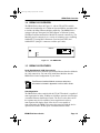
book Page 1 Friday, April 19, 1996 9:53 AM BOOKTITLE2 OPTIONAL BRIM-E100 USER’S GUIDE book Page i Friday, April 19, 1996 9:53 AM NOTICE Cabletron Systems reserves the right to make changes in specifications and other information contained in this document without prior notice. The reader should in all cases consult Cabletron Systems to determine whether any such changes have been made. The hardware, firmware, or software described in this manual is subject to change without notice. IN NO EVENT SHALL CABLETRON SYSTEMS BE LIABLE FOR ANY INCIDENTAL, INDIRECT, SPECIAL, OR CONSEQUENTIAL DAMAGES WHATSOEVER (INCLUDING BUT NOT LIMITED TO LOST PROFITS) ARISING OUT OF OR RELATED TO THIS MANUAL OR THE INFORMATION CONTAINED IN IT, EVEN IF CABLETRON SYSTEMS HAS BEEN ADVISED OF, KNOWN, OR SHOULD HAVE KNOWN, THE POSSIBILITY OF SUCH DAMAGES. Copyright 1996 by Cabletron Systems, Inc., P.O. Box 5005, Rochester, NH 03866-5005 All Rights Reserved Printed in the United States of America Order Number: 9031665-03 April 1996 SPECTRUM, LANVIEW, MicroMMAC, and BRIM are registered trademarks and Element Manager and EMM-E6 are trademarks of Cabletron Systems, Inc. All other product names mentioned in this manual may be trademarks or registered trademarks of their respective companies. Printed on BRIM-E100 User’s Guide Recycled Paper i book Page ii Friday, April 19, 1996 9:53 AM Notice FCC NOTICE This device complies with Part 15 of the FCC rules. Operation is subject to the following two conditions: (1) this device may not cause harmful interference, and (2) this device must accept any interference received, including interference that may cause undesired operation. NOTE: This equipment has been tested and found to comply with the limits for a Class A digital device, pursuant to Part 15 of the FCC rules. These limits are designed to provide reasonable protection against harmful interference when the equipment is operated in a commercial environment. This equipment uses, generates, and can radiate radio frequency energy and if not installed in accordance with the operator’s manual, may cause harmful interference to radio communications. Operation of this equipment in a residential area is likely to cause interference in which case the user will be required to correct the interference at his own expense. WARNING: Changes or modifications made to this device which are not expressly approved by the party responsible for compliance could void the user’s authority to operate the equipment. DOC NOTICE This digital apparatus does not exceed the Class A limits for radio noise emissions from digital apparatus set out in the Radio Interference Regulations of the Canadian Department of Communications. Le présent appareil numérique n’émet pas de bruits radioélectriques dépassant les limites applicables aux appareils numériques de la class A prescrites dans le Règlement sur le brouillage radioélectrique édicté par le ministère des Communications du Canada. VCCI NOTICE This equipment is in the 1st Class Category (information equipment to be used in commercial and/or industrial areas) and conforms to the standards set by the Voluntary Control Council for Interference by Information Technology Equipment (VCCI) aimed at preventing radio interference in commercial and/or industrial areas. Consequently, when used in a residential area or in an adjacent area thereto, radio interference may be caused to radios and TV receivers, etc. Read the instructions for correct handling. ii BRIM-E100 User’s Guide book Page iii Friday, April 19, 1996 9:53 AM Notice CABLETRON SYSTEMS, INC. PROGRAM LICENSE AGREEMENT IMPORTANT: Before utilizing this product, carefully read this License Agreement. This document is an agreement between you, the end user, and Cabletron Systems, Inc. (“Cabletron”) that sets forth your rights and obligations with respect to the Cabletron software program (the “Program”) contained in this package. The Program may be contained in firmware, chips or other media. BY UTILIZING THE ENCLOSED PRODUCT, YOU ARE AGREEING TO BECOME BOUND BY THE TERMS OF THIS AGREEMENT, WHICH INCLUDES THE LICENSE AND THE LIMITATION OF WARRANTY AND DISCLAIMER OF LIABILITY. IF YOU DO NOT AGREE TO THE TERMS OF THIS AGREEMENT, PROMPTLY RETURN THE UNUSED PRODUCT TO THE PLACE OF PURCHASE FOR A FULL REFUND. CABLETRON SOFTWARE PROGRAM LICENSE 1. LICENSE. You have the right to use only the one (1) copy of the Program provided in this package subject to the terms and conditions of this License Agreement. You may not copy, reproduce or transmit any part of the Program except as permitted by the Copyright Act of the United States or as authorized in writing by Cabletron. 2. OTHER RESTRICTIONS. You may not reverse engineer, decompile, or disassemble the Program. 3. APPLICABLE LAW. This License Agreement shall be interpreted and governed under the laws and in the state and federal courts of New Hampshire. You accept the personal jurisdiction and venue of the New Hampshire courts. EXCLUSION OF WARRANTY AND DISCLAIMER OF LIABILITY 1. EXCLUSION OF WARRANTY. Except as may be specifically provided by Cabletron in writing, Cabletron makes no warranty, expressed or implied, concerning the Program (including its documentation and media). CABLETRON DISCLAIMS ALL WARRANTIES, OTHER THAN THOSE SUPPLIED TO YOU BY CABLETRON IN WRITING, EITHER EXPRESSED OR IMPLIED, INCLUDING BUT NOT LIMITED TO IMPLIED WARRANTIES OF MERCHANTABILITY AND FITNESS FOR A PARTICULAR PURPOSE, WITH RESPECT TO THE PROGRAM, THE ACCOMPANYING WRITTEN MATERIALS, AND ANY ACCOMPANYING HARDWARE. 2. NO LIABILITY FOR CONSEQUENTIAL DAMAGES. IN NO EVENT SHALL CABLETRON OR ITS SUPPLIERS BE LIABLE FOR ANY DAMAGES WHATSOEVER (INCLUDING, WITHOUT LIMITATION, DAMAGES FOR LOSS OF BUSINESS, PROFITS, BUSINESS INTERRUPTION, LOSS OF BUSINESS INFORMATION, SPECIAL, INCIDENTAL, CONSEQUENTIAL, OR RELIANCE DAMAGES, OR OTHER LOSS) ARISING OUT OF THE USE OR INABILITY TO USE THIS CABLETRON PRODUCT, EVEN IF CABLETRON HAS BEEN ADVISED OF THE POSSIBILITY OF SUCH DAMAGES. BECAUSE SOME STATES DO NOT ALLOW THE EXCLUSION OR LIMITATION OF LIABILITY FOR CONSEQUENTIAL OR INCIDENTAL DAMAGES, OR ON THE DURATION OR LIMITATION OF IMPLIED WARRANTIES, IN SOME INSTANCES THE ABOVE LIMITATIONS AND EXCLUSIONS MAY NOT APPLY TO YOU. BRIM-E100 User’s Guide iii book Page iv Friday, April 19, 1996 9:53 AM Notice UNITED STATES GOVERNMENT RESTRICTED RIGHTS The enclosed product (a) was developed solely at private expense; (b) contains “restricted computer software” submitted with restricted rights in accordance with Section 52227-19 (a) through (d) of the Commercial Computer Software - Restricted Rights Clause and its successors, and (c) in all respects is proprietary data belonging to Cabletron and/or its suppliers. For Department of Defense units, the product is licensed with “Restricted Rights” as defined in the DoD Supplement to the Federal Acquisition Regulations, Section 52.227-7013 (c) (1) (ii) and its successors, and use, duplication, disclosure by the Government is subject to restrictions as set forth in subparagraph (c) (1) (ii) of the Rights in Technical Data and Computer Software clause at 252.2277013. Cabletron Systems, Inc., 35 Industrial Way, Rochester, New Hampshire 03867-0505. iv BRIM-E100 User’s Guide book Page v Friday, April 19, 1996 9:53 AM CONTENTS CHAPTER 1 INTRODUCTION 1.1 Using This Manual....................................................................... 1-1 1.2 Document Conventions ............................................................... 1-2 1.3 Getting Help................................................................................. 1-2 1.4 BRIM-E100 Overview .................................................................. 1-3 1.5 BRIM-E100 Features................................................................... 1-3 1.6 BRIM-E100 Specifications........................................................... 1-5 1.7 Agency Approvals........................................................................ 1-5 1.8 Related Manuals.......................................................................... 1-6 CHAPTER 2 CABLING REQUIREMENTS 2.1 UTP Cable Specifications............................................................ 2-1 2.2 Multimode Specifications for the FE-100FX ................................ 2-3 2.3 Network Cable Lengths ............................................................... 2-3 CHAPTER 3 INSTALLATION 3.1 Unpacking the BRIM-E100 .......................................................... 3-1 3.2 Installing Fast Ethernet Interface Modules .................................. 3-2 3.3 Installing the BRIM-E100............................................................. 3-5 3.3.1 Installing a BRIM-E100 in a MIM .................................... 3-5 3.3.2 Installing a BRIM-E100 in a Hub..................................... 3-7 CHAPTER 4 CONNECTING TO THE NETWORK 4.1 Connecting the BRIM to the Network .......................................... 4-1 4.1.1 Connecting a UTP Segment to the BRIM-E100 ............. 4-1 4.1.2 Connecting a Multimode Segment to the FE-100FX ...... 4-3 4.1.2.1 Fiber Connection: SC Connectors ..................... 4-3 4.1.2.2 Fiber Connection: SC to ST............................... 4-5 CHAPTER 5 LOCAL MANAGEMENT 5.1 Local Management Keyboard Conventions................................. 5-2 5.2 The BRIM-E100 Setup Screen .................................................... 5-3 5.3 BRIM-E100 Setup........................................................................ 5-4 5.3.1 FE-100TX Configuration ................................................. 5-5 5.3.2 FE-100FX Configuration ................................................. 5-6 BRIM-E100 User’s Guide v book Page vi Friday, April 19, 1996 9:53 AM Contents CHAPTER 6 LANVIEW LEDs 6.1 BRIM-E100 LEDs.........................................................................6-1 6.2 FE-100TX LED.............................................................................6-2 APPENDIX A A.1 FAST ETHERNET INTERFACE MODULE SPECIFICATIONS Module Specifications ................................................................. A-1 A.1.1 FE-100TX ....................................................................... A-1 A.1.2 FE-100FX ....................................................................... A-2 INDEX vi BRIM-E100 User’s Guide book Page 1 Friday, April 19, 1996 9:53 AM CHAPTER 1 INTRODUCTION Welcome to the Cabletron Systems BRIM-E100 User’s Guide. This manual describes features, explains installation procedures, and provides specifications for the Cabletron Systems 10/100 Mbps Bridge/Router Interface Module (BRIM). The BRIM-E100 resides in, and provides additional connectivity/functionality to, various Cabletron Systems Media Interface Modules (MIMs) and standalone hubs. 1.1 USING THIS MANUAL Read through this manual completely to familiarize yourself with its content and to gain an understanding of the features and capabilities of the BRIM-E100. You should have a general working knowledge of Ethernet and IEEE 802.3u type data communications networks and their physical layer components before using the BRIM-E100. Chapter 1, Introduction, outlines the contents of this manual, describes BRIM-E100 features, lists specifications, and concludes with a list of related manuals. Chapter 2, Cabling Requirements, provides cable specifications and maximum cable lengths for the various media types. Chapter 3, Installation, describes how to install 100 Mbps Fast Ethernet Interface Modules into the BRIM-E100. This chapter also explains how to install a BRIM-E100 into a MIM or standalone hub. Chapter 4, Connecting to the Network, explains how to connect the BRIM-E100 to the network using the various media types. Chapter 5, Local Management, describes how to use Local Management screens to set up the BRIM-E100. Chapter 6, LANVIEW LEDs, describes how to use the BRIM-E100 LEDs to monitor BRIM performance and status. Appendix A, Fast Ethernet Interface Module Specifications, provides specifications, cabling information and switch settings for Fast Ethernet Interface Modules used in the BRIM-E100. BRIM-E100 User’s Guide Page 1-1 book Page 2 Friday, April 19, 1996 9:53 AM Chapter 1: Introduction 1.2 DOCUMENT CONVENTIONS This document uses the following conventions. NOTE Note symbol. Calls the reader’s attention to any item of information that may be of special importance. Tip symbol. Conveys helpful hints concerning procedures or actions. TIP ! Caution symbol. Contains information essential to avoid damage to the equipment. CAUT ION Warning symbol. Warns against an action that could result in equipment damage, personal injury or death. 1.3 GETTING HELP If you need additional support related to this device, or if you have any questions, comments, or suggestions concerning this manual, contact Cabletron Systems Technical Support: By phone By CompuServe By Internet mail By FTP Login Password Page 1-2 (603) 332-9400 Monday – Friday; 8 A.M. – 8 P.M. Eastern Time GO CTRON from any ! prompt [email protected] ctron.com (134.141.197.25) anonymous your email address BRIM-E100 User’s Guide book Page 3 Friday, April 19, 1996 9:53 AM BRIM-E100 Overview 1.4 BRIM-E100 OVERVIEW The BRIM-E100 (shown in Figure 1-1 with an FE-100TX installed) extends the functionality of a Cabletron Systems MIM or standalone hub to include 100 Mbps Ethernet bridging capability. The BRIM-E100 is equipped with one front panel slot that supports a Cabletron Systems 100 Mbps Fast Ethernet Interface Module for network connectivity. The Modules provide connectivity to a variety of technology types including 100BASE-TX (using RJ45 connectors on twisted pair cable) and 100BASE-FX (using SC connectors on fiber optic cable). BRIM-E100 = x 10 100 FE-100TX RX TX 1665_01 Figure 1-1 The BRIM-E100 1.5 BRIM-E100 FEATURES Local Area Network (LAN) Connectivity The BRIM-E100 uses Cabletron Systems Fast Ethernet Interface Modules for LAN connectivity. You can easily install these Modules into the BRIM-E100 for the configuration of your choice. NOTE Fast Ethernet Interface Module connector and pinout information is located in Appendix A of this User’s Guide. Auto-Negotiation The BRIM-E100 when coupled with the FE-100TX module is capable of auto-negotiation for either 10 Mbps or 100 Mbps operation in full duplex or standard Ethernet (half duplex) mode. The device at the other end of the segment must also be capable of auto-negotiation in order to auto-negotiate full duplex mode. If the device is not capable of auto-negotiation, the BRIM-E100 senses the speed at which the device operates and switches to that speed in standard Ethernet mode. BRIM-E100 User’s Guide Page 1-3 book Page 4 Friday, April 19, 1996 9:53 AM Chapter 1: Introduction Full Duplex Functionality The BRIM-E100 has the ability to transmit and receive at the same time. Full duplex operation allows the BRIM-E100 when coupled with the FE-100TX Fast Ethernet Interface Module to provide either 20 or 200 Megabit bandwidth throughput as long as the device at the other end of the segment supports full duplex mode. The BRIM-E100 is also capable of operating in either full or half duplex mode at 100 Mbps when equipped with the Fiber Optic FE-100FX Fast Ethernet Interface Module. The BRIM-E100 is configured through Local Management on the management module (i.e., the EMM-E6, MicroMMAC, etc.) to operate in either full duplex (20/200 Mbps) or standard Ethernet (10/100 Mbps) mode. MIB Support For information on how to extract and compile individual MIBs, contact Cabletron Systems Technical Support. Refer to Section 1.3, Getting Help. LANVIEW Diagnostic LEDs Cabletron Systems equips the BRIM-E100 with the LANVIEW visual diagnostic and status monitoring system. LANVIEW LEDs provide “at-a-glance” network status information. Fast Ethernet Interface Module Connectivity Fast Ethernet Interface Modules enable the configuration of the BRIM-E100 to support a variety of media types. Cabletron Systems currently offers the Fast Ethernet Interface Modules shown in Table 1-1. Table 1-1 Fast Ethernet Interface Modules Module Media Type Connector FE-100TX 10/100BASE-TX UTP (Unshielded Twisted Pair) RJ45 FE-100FX 100BASE-FX Multimode Fiber SC Page 1-4 BRIM-E100 User’s Guide book Page 5 Friday, April 19, 1996 9:53 AM BRIM-E100 Specifications 1.6 BRIM-E100 SPECIFICATIONS This section describes the BRIM-E100 operating specifications. Cabletron Systems reserves the right to change these specifications at any time without notice. Environmental Requirements Operating Temperature: 5° to 40°C (41° to 104°F) Storage Temperature: -30° to 90°C (-22° to 194°F) Operating Humidity: 5% to 95% (non-condensing) 1.7 AGENCY APPROVALS Safety This unit meets the safety requirements of UL 1950, CSA C22.2 No. 950, and EN 60950. EMI This unit meets the EMI requirements of FCC Part 15 Class A, EN 55022 Class A, and VCCI Class I. EMC This unit meets the EMC requirements of EN 50082-1 including IEC 801-2 (ESD), IEC 801-3 (Radiated Susceptibility), and IEC 801-4 (EFT/B). BRIM-E100 User’s Guide Page 1-5 book Page 6 Friday, April 19, 1996 9:53 AM Chapter 1: Introduction 1.8 RELATED MANUALS Use the following manuals to supplement the procedures, and other technical data provided in this manual. This manual references procedures in these manuals, as appropriate, but does not repeat them. Cabletron Systems EMM-E6 User’s Guide Cabletron Systems ESXMIM Installation Guide Cabletron Systems ESXMIM Local Management Guide Cabletron Systems MicroMMAC User’s Guide Cabletron Systems NBR-620/420/220 Installation Guide Cabletron Systems NBR-620/420/220 Local Management Guide Page 1-6 BRIM-E100 User’s Guide book Page 1 Friday, April 19, 1996 9:53 AM CHAPTER 2 CABLING REQUIREMENTS This chapter describes the cabling requirements for the BRIM-E100. The network must meet the requirements and conditions specified in this chapter to obtain satisfactory performance from this equipment. Failure to follow these guidelines could result in poor network performance. 2.1 UTP CABLE SPECIFICATIONS The BRIM-E100 with an FE-100TX Fast Ethernet Interface Module installed provides an RJ45 connection that supports Unshielded Twisted Pair (UTP) cabling. The device at the other end of the twisted pair segment must meet IEEE 802.3u 100BASE-TX specifications in order for the devices to operate properly at 100 Mbps. Use Category 5 UTP cabling for networks operating at 100 Mbps. Category 3, 4, or 5 UTP cabling may be used for networks operating at 10 Mbps. NOTE The BRIM-E100 with an FE-100TX Fast Ethernet Interface Module installed is capable of operating at either 10 or 100 Mbps. The FE-100TX automatically senses the speed of the other device and adjusts its speed accordingly. When connecting a 100BASE-TX Twisted Pair Segment to the BRIM-E100 twisted pair network port, the network must meet the following requirements: Length The IEEE 802.3u 100BASE-TX standard requires that 100BASE-TX devices be capable of transmitting over a 100 meter (328 foot) link using Category 5 UTP cable or Category 3, 4, or 5 cable for 10 Mbps operation. Impedance Unshielded Twisted Pair cables typically have an impedance from 85 to 110 ohms. BRIM-E100 User’s Guide Page 2-1 book Page 2 Friday, April 19, 1996 9:53 AM Chapter 2: Cabling Requirements Jitter Intersymbol interference and reflections cause jitter in the bit cell timing, resulting in data errors. A 100BASE-TX link must not generate more than 1.4 nanoseconds (ns) of jitter. If the cable meets the impedance requirements for a 100BASE-TX link, jitter should not be a concern. Crosstalk Crosstalk is caused by signal coupling between the different cable pairs contained within a multi-pair cable bundle. 100BASE-TX transceivers are designed so that the user does not need to be concerned about cable crosstalk, provided the cable meets all other requirements. Noise Noise is caused by either crosstalk or externally induced impulses. Impulse noise may cause data errors if the impulses occur at very specific times during data transmission. Generally, the user need not be concerned about noise. If noise-related data errors are suspected, it may be necessary to either reroute the cable or eliminate the source of the impulse noise. UTP Propagation Delay Propagation delay is the amount of time it takes data to travel from the sending device to the receiving device. Total propagation delay allowed for the network is 256 bit times. 256 bit times is equivalent to 2.56 microseconds (µs) at 100 Mbps operation or to 25.6 µs at 10 Mbps operation. If the total propagation delay between any two nodes on the network exceeds 256 bit times, then further segmentation of the network through the use of bridges or other devices is required. Temperature The attenuation of PVC insulated cable varies significantly with temperature. At temperatures greater than 40°C (104°F), Cabletron Systems recommends the use of plenum-rated cables to ensure that cable attenuation remains within specification. Page 2-2 BRIM-E100 User’s Guide book Page 3 Friday, April 19, 1996 9:53 AM Multimode Specifications for the FE-100FX 2.2 MULTIMODE SPECIFICATIONS FOR THE FE-100FX The BRIM-E100 supports the Cabletron Systems FE-100FX. The FE-100FX meets IEEE 802.3u standards. When connecting a fiber optic segment to the BRIM-E100 with the FE-100FX module installed, the network must meet the following requirements: Cable Loss Test the fiber optic cable with a fiber optic attenuation test set adjusted for an 850 nanometer (nm) wavelength. This test verifies that the signal loss in a cable is within an acceptable level. The maximum loss for a multimode fiber optic cable is 11.0 decibels (dB). Fiber Optic Budget and Propagation Delay Determine the maximum fiber optic cable length by calculating the fiber optic budget delay and total network propagation before fiber optic cable runs are incorporated in any network design. Fiber optic budget is the combination of the optical loss due to the fiber optic cable, in-line splices, and fiber optic connectors. Propagation delay (collision delay) is the amount of time it takes data to travel from the sending device to the receiving device. Total propagation delay allowed for the entire network is 256 bit times (2.56 µs). If the total propagation delay between any two nodes on the network exceeds 2.56 µs, then further segmentation of the network through the use of bridges or other devices is required. 2.3 NETWORK CABLE LENGTHS This section details the maximum network cable lengths specified by the IEEE 802.3u standard. As stated in the previous sections, the physical size of the network is limited primarily by propagation delay. The propagation delay cannot exceed 256 bit times. A 100BASE-TX/FX network might use all copper (UTP) links, all fiber links or a combination of both. The maximum length of any segment is determined by the types and combination of links and by the type of repeater (if any) between segments. IEEE 802.3u standards specify two repeater classes (Class 1 and Class 2) and the maximum cable lengths for each media type. BRIM-E100 User’s Guide Page 2-3 book Page 4 Friday, April 19, 1996 9:53 AM Chapter 2: Cabling Requirements If you are installing this BRIM into a 100BASE-TX/FX environment with repeaters, use the repeater instruction manual to determine maximum cable lengths when laying out your network. UTP Maximum Cable Lengths An unshielded twisted pair copper segment in a 100BASE-TX environment may be no more than 100 meters in length. Multimode Fiber Cable Lengths The maximum distance between two Data Terminal Equipment (DTE) devices on a 100BASE-FX segment may be no more than 412 meters in half duplex mode or 2 Kilometers (DTE to DTE) in full duplex mode. Page 2-4 BRIM-E100 User’s Guide book Page 1 Friday, April 19, 1996 9:53 AM CHAPTER 3 INSTALLATION This chapter contains instructions for unpacking the BRIM-E100, installing Fast Ethernet Interface Modules, and installing the BRIM-E100 into Cabletron Systems devices that support BRIM technology. The following equipment is needed to install the BRIM-E100 and Fast Ethernet Interface Modules: • 1 disposable grounding strap (provided with any MIM or hub) • 1 Phillips screwdriver ! CAUT ION The BRIM-E100 and the host hub are sensitive to static discharges. Use a grounding strap and observe all static precautions during this procedure. Failure to do so could result in damage to the BRIM-E100 or the host hub. 3.1 UNPACKING THE BRIM-E100 Unpack the BRIM-E100 as follows: 1. Remove the shipping box material covering the BRIM-E100. 2. Carefully remove the module from the shipping box. Leave the module in its non-conductive bag until you are ready to install. 3. Attach the disposable grounding strap to your wrist and to a proper ground. Refer to the instructions outlined on the grounding strap package. 4. After removing the module from its non-conductive bag, visually inspect the device. If you notice any signs of damage, contact Cabletron Systems Technical Support immediately. BRIM-E100 User’s Guide Page 3-1 book Page 2 Friday, April 19, 1996 9:53 AM Chapter 3: Installation 3.2 INSTALLING FAST ETHERNET INTERFACE MODULES Install a Fast Ethernet Interface Module into the BRIM-E100 as follows: 1. Attach the disposable grounding strap to your wrist and to a proper ground. Refer to the instructions outlined on the disposable grounding strap package. 2. Remove the screws securing the Fast Ethernet Interface Module coverplate to the standoffs on the BRIM-E100 and remove the coverplate from the BRIM-E100 (see Figure 3-1). 3. Remove the screw from the top of the standoff at the rear of the BRIM-E100. COVERPLATE RX TX STANDOFF BRIM -E1 00 166509 Figure 3-1 Page 3-2 Removing the Coverplate on the BRIM-E100 BRIM-E100 User’s Guide book Page 3 Friday, April 19, 1996 9:53 AM Installing Fast Ethernet Interface Modules ! CAUT ION Failure to remove the BRIM-E100 faceplate before installing the Fast Ethernet Interface Module may result in damage to the BRIM-E100 and/or the Fast Ethernet Interface Module. 4. Remove the two faceplate screws from the BRIM-E100. See Figure 3-2. 5. Remove the faceplate. RX TX BRIM -E1 00 1665_10 Figure 3-2 BRIM-E100 User’s Guide Removing the Faceplate Page 3-3 book Page 4 Friday, April 19, 1996 9:53 AM Chapter 3: Installation 6. Carefully lower the Fast Ethernet Interface Module onto the standoffs while inserting the connector pins of the Fast Ethernet Interface Module into the connector on the BRIM-E100. See Figure 3-3. CONNECTOR STANDOFF FE-1 00T RX BRIM X 10 100 CONNECTOR -E1 TX 00 1665_02 Figure 3-3 Installing Fast Ethernet Interface Modules 7. Press down firmly on the Fast Ethernet Interface Module until the pins slide all the way into the connector holes. Ensure that the Fast Ethernet Interface Module seats flush on the standoffs. 8. Secure the Fast Ethernet Interface Module to the standoffs with the three screws removed from the BRIM-E100 in steps 2 and 3. Page 3-4 BRIM-E100 User’s Guide book Page 5 Friday, April 19, 1996 9:53 AM Installing the BRIM-E100 3.3 INSTALLING THE BRIM-E100 A BRIM-E100 can be installed in most Cabletron Systems devices that support BRIM technology (e.g., EMM-E6 or MicroMMAC). Refer to the release notes for the version of firmware running on the Cabletron Systems device to make sure that the BRIM-E100 is supported. The following subsections provide generic instructions for installing a BRIM-E100 in a MIM or standalone hub. Refer to your specific MIM or standalone hub documentation for exact BRIM slot and connector locations. ! CAUT ION Only qualified personnel should install the BRIM-E100. Incorrect installation could result in damage to the equipment or reduced network performance. 3.3.1 Installing a BRIM-E100 in a MIM Install a BRIM-E100 in a MIM that supports BRIM technology as follows: 1. Power down the MMAC hub and remove all power cords. NOTE Cabletron Systems recommends that you power down your hub even though Cabletron Systems MIMs have “hot swap” capabilities. 2. Disconnect all cables from the MIM. Note the ports to which these cables attach. 3. Attach the disposable grounding strap to your wrist and to a proper ground. Refer to the instructions outlined on the disposable grounding strap package. 4. Unscrew the top and bottom knurled knobs of the MIM faceplate. 5. Slide out the MIM, and place it on its side with the internal components facing up. 6. Remove the mounting screws and the BRIM coverplate. See Figure 3-4. BRIM-E100 User’s Guide Page 3-5 book Page 6 Friday, April 19, 1996 9:53 AM Chapter 3: Installation STANDOFF SCREW STANDOFF BRIM COVERPLATE FACEPLATE MOUNTING SCREW 1028_03 Figure 3-4 Removing the BRIM Coverplate MOUNTING SCREW 100 10 X 0T 00 -E1 -10 FE RIM B STANDOFF RX TX BRIM CONNECTOR FACEPLATE MOUNTING SCREW Figure 3-5 Page 3-6 Installing the BRIM-E100 BRIM-E100 User’s Guide book Page 7 Friday, April 19, 1996 9:53 AM Installing the BRIM-E100 7. Place your BRIM-E100 behind the MIM faceplate. See Figure 3-5. 8. Insert the connector pins of the BRIM-E100 into the BRIM connector on the MIM. 9. Press down firmly on the back of the BRIM-E100 until the pins slide all the way into the connector holes. NOTE Ensure that the standoffs on the MIM align with the standoff screw holes on the BRIM. 10. Reinstall the mounting screws, and install the standoff screws. 11. Reinstall the MIM in the MMAC. 12. Reattach the network cabling to the MIM. 13. Reattach all MMAC power cords and power up the hub. 14. Refer to Chapter 5 for instructions on configuring the BRIM-E100 through Local Management. Appendix A provides Fast Ethernet Interface Module connector and pinout information. 3.3.2 Installing a BRIM-E100 in a Hub Install a BRIM-E100 into a standalone hub that supports BRIM technology as follows: 1. Power down the hub and remove the power cord. 2. Disconnect all cables from the hub. Note the ports to which these cables attach. Ensure that you remove the power cord and ONLY the screws required to remove the chassis cover. Failure to comply could result in an electric shock hazard. 3. Attach the disposable grounding strap to your wrist and a proper ground. Refer to the instructions outlined on the disposable grounding strap package. BRIM-E100 User’s Guide Page 3-7 book Page 8 Friday, April 19, 1996 9:53 AM Chapter 3: Installation 4. Remove the hub chassis cover. Refer to your specific hub documentation for instructions on removing the hub chassis cover. 5. Remove the faceplate mounting screws and the BRIM coverplate. See Figure 3-4. 6. Place the BRIM-E100 behind the hub faceplate. See Figure 3-5. 7. Insert the connector pins of the BRIM-E100 into the hub connector. 8. Press down firmly on the back of the BRIM-E100 until the pins slide all the way into the connector holes. ! Ensure that the standoffs on the hub align with the standoff screw holes on the BRIM-E100. CAUT ION 9. Reinstall the faceplate mounting screws, and install the standoff screws. Ensure that the chassis cover is in place before reconnecting the power cord. 10. Reattach the chassis cover to the hub, reconnect the power cord, and reconnect the hub to your network. 11. Refer to Chapter 5 for instructions on configuring the BRIM-E100 through Local Management. Appendix A provides Fast Ethernet Interface Module connector and pinout information. Page 3-8 BRIM-E100 User’s Guide book Page 1 Friday, April 19, 1996 9:53 AM CHAPTER 4 CONNECTING TO THE NETWORK This chapter outlines the procedure for connecting the BRIM-E100 to a network. 4.1 CONNECTING THE BRIM TO THE NETWORK The procedure for connecting network segments to the BRIM-E100 depends on which Fast Ethernet Interface Module is installed in the BRIM. The FE-100TX Fast Ethernet Interface Module provides an RJ45 connection for Unshielded Twisted Pair (UTP) wiring. The FE-100FX provides an SC style connector for use with multimode fiber optic cabling. Refer to the following list and perform the procedure described in the subsections that apply to your configuration: • BRIM-E100 with FE-100TX Section 4.1.1 • BRIM-E100 with FE-100FX Section 4.1.2 Prior to connecting the network cabling check the connectors for the proper pinouts as shown in Appendix A. 4.1.1 Connecting a UTP Segment to the BRIM-E100 The BRIM-E100 with an FE-100TX installed is often used to provide a connection between the BRIM and a bridge, router, or switch. Usually, in this configuration, a “straight-through” cable is used and the crossover switch shown in Figure 4-1 is set to “not crossed over.” Normally, when connecting devices to like devices, crossing over of the transmit and receive pairs must occur. Before connecting a segment to the FE-100TX, check each end of the segment to determine if the wires have been crossed over for the proper connection. If the wires do not cross over, use the switch on the FE-100TX to internally cross over the RJ45 port. Refer to Figure 4-1 to properly set the FE-100TX crossover switch. BRIM-E100 User’s Guide Page 4-1 book Page 2 Friday, April 19, 1996 9:53 AM Chapter 4: Connecting to the Network POSITION X (CROSSED OVER) = (NOT CROSSED OVER) POSITION 1. TX+ 2. TX3. RX+ 4. NC 5. NC 6. RX7. NC 8. NC = x 10 100 FE-100TX 1. RX+ 2. RX3. TX+ 4. NC 5. NC 6. TX7. NC 8. NC 166505 Figure 4-1 FE-100TX Crossover Switch Connect an FE-100TX to a twisted pair segment as follows: 1. Connect the twisted pair segment to the module by inserting the RJ45 connector on the twisted pair segment into the RJ45 port on the module. See Figure 4-1. 2. Check that the RX LED on the BRIM-E100 is green or flashing yellow (refer to Chapter 6). If the LED is off, perform each of the following steps until it is on: a. Check that the 100BASE-TX device at the other end of the twisted pair segment is powered up. b. Verify that the RJ45 connector on the twisted pair segment has the proper pinouts. c. Check the cable for continuity. d. Check that the twisted pair connection meets dB loss and cable specifications outlined in Chapter 2, Section 2.1. e. Check that the crossover switch is in the correct position. If a link is not established, contact Cabletron Systems Technical Support. Page 4-2 BRIM-E100 User’s Guide book Page 3 Friday, April 19, 1996 9:53 AM Connecting the BRIM to the Network 4.1.2 Connecting a Multimode Segment to the FE-100FX The FE-100FX has an SC style network port (see Figure 4-2). Cabletron Systems supplies fiber optic cable that uses keyed SC style connectors to insure proper crossover of the transmit and receive fibers. NOTE An odd number of crossovers (preferably one) must be maintained between devices so that the transmit port of one device is connected to the receive port of the other device and vice versa. If you are using fiber optic cable that uses SC style connectors that do not resemble MIC style connectors or if the cable has SC connectors on one end and a different type such as ST connectors on the other, you need to ensure that proper crossover occurs. Read and follow the directions in Section 4.1.2.2, Fiber Connection: SC to ST. 4.1.2.1 Fiber Connection: SC Connectors ! CAUT ION Do not touch the ends of the fiber optic strands, and do not let the ends come in contact with dust, dirt, or other contaminants. Contamination of the ends causes problems in data transmissions. If the ends become contaminated, clean them with alcohol using a soft, clean, lint free cloth. 1. Remove the protective plastic covers from the fiber optic ports on the applicable port on the module and from the ends of the connectors. 2. Insert one end of the SC connector into the FE-100FX installed in the BRIM-E100. See Figure 4-2. BRIM-E100 User’s Guide Page 4-3 book Page 4 Friday, April 19, 1996 9:53 AM Chapter 4: Connecting to the Network 100 BRIM-E X FE-100F RX TX 166506 Figure 4-2 FE-100FX Port 3. At the other end of the fiber optic cable, attach the SC connector to the other device. 4. Check that the BRIM-E100 RX LED is green or flashing yellow (refer to Chapter 6, LANVIEW LEDs). If the LED is off, perform the following steps until it is on: a. Check that the power is turned on for the device at the other end of the link. b. Verify proper crossover of fiber strands between the applicable port on the BRIM-E100 and the fiber optic device at the other end of the fiber optic link segment. c. Verify that the fiber connection meets the dB loss specifications outlined in Chapter 2. If a link is not established, contact Cabletron Systems Technical Support. Page 4-4 BRIM-E100 User’s Guide book Page 5 Friday, April 19, 1996 9:53 AM Connecting the BRIM to the Network 4.1.2.2 Fiber Connection: SC to ST Follow the directions in this section if you are connecting a non-Cabletron Systems device to the FE-100FX using different types of connectors such as SC to ST. The physical communication link consists of two strands of fiber optic cabling: the transmit and the receive. Connect the transmit strand from the applicable port on the module to the receive port of the fiber optic Ethernet device at the other end of the segment. Connect the receive strand of the applicable port on the module to the transmit port of the fiber optic Ethernet device. Label the fiber optic cable to indicate which fiber is receive and which is transmit. Cabletron Systems fiber optic cable is labeled so that one fiber is labeled 1, and the other fiber is labeled 2 at both ends of the cable. If the cable was not purchased from Cabletron Systems, label the cable as described above. Connect a fiber optic link segment as follows: ! CAUT ION Do not touch the ends of the fiber optic strands, and do not let the ends come in contact with dust, dirt, or other contaminants. Contamination of the ends causes problems in data transmissions. If the ends become contaminated, clean them with alcohol using a soft, clean, lint free cloth. 1. Remove the protective plastic covers from the fiber optic ports on the applicable port on the module and from the ends of the connectors on each fiber strand. 2. Attach the fiber labeled 1 to the receive port on the FE-100FX. See Figure 4-3. 3. Attach the fiber labeled 2 to the transmit port on the FE-100FX. 4. At the other end of the fiber optic cable, attach the fiber labeled 1 to the transmit port of the device. BRIM-E100 User’s Guide Page 4-5 book Page 6 Friday, April 19, 1996 9:53 AM Chapter 4: Connecting to the Network 100 BRIM-E X FE-100F RX TX 166507 Figure 4-3 1 2 Connecting Individual Leads to the FE-100FX 5. Attach the fiber labeled 2 to the receive port. 6. Check that the BRIM-E100 Receive (RX) LED is green or flashing yellow. If the LED is off, perform the following steps until it is on: a. Check that the power is turned on for the device at the other end of the link. b. Verify proper crossover of fiber strands between the FE-100FX and the fiber optic device at the other end of the fiber optic link segment by reversing the transmit and receive fibers at one end of the segment. c. Verify that the fiber connection meets the dB loss specifications outlined in Chapter 2. If a link is not established, contact Cabletron Systems Technical Support. The BRIM-E100 is now ready to be set up through Local Management. Proceed to Chapter 5, Local Management, to configure the BRIM-E100. Page 4-6 BRIM-E100 User’s Guide book Page 1 Friday, April 19, 1996 9:53 AM CHAPTER 5 LOCAL MANAGEMENT This chapter explains how to configure the BRIM-E100 through Local Management. The BRIM-E100 Setup screen appears as a Local Management selection and displays the current settings of the BRIM-E100 after the BRIM-E100 is installed into a MIM or standalone hub. Local Management allows the user to set these parameters manually. Refer to the MIM or standalone hub User’s Guide for instructions about how to set up and access Local Management. Complete the following steps before configuring the BRIM-E100 through Local Management. • A Fast Ethernet Interface Module must be installed in the BRIM-E100. • The BRIM-E100 must be installed in a MIM or standalone hub. • The device must be up and running. • A Local Management terminal must be configured and properly connected to the intelligent device in which the BRIM resides. BRIM-E100 User’s Guide Page 5-1 book Page 2 Friday, April 19, 1996 9:53 AM Chapter 5: Local Management 5.1 LOCAL MANAGEMENT KEYBOARD CONVENTIONS All key names appear in this manual as capital letters. For example, the Enter key appears as ENTER and the Backspace key appears as BACKSPACE. Table 5-1 explains the keyboard conventions used in this manual as well as the key functions. Table 5-1 Keyboard Conventions Key Function ENTER (RETURN) key ENTER (RETURN) implements a selection. “Press ENTER” means that you can press either RETURN or ENTER. SPACE bar and BACKSPACE key These keys cycle through selections in some Local Management fields. Use the SPACE bar to cycle forward through selections and use BACKSPACE to cycle backward through selections. Arrow Keys These are navigation keys. Use the UP-ARROW, DOWN-ARRROW, LEFT-ARROW, and RIGHT-ARROW keys to move the screen cursor. For example, “Use the arrow keys” means to press whichever arrow key moves the cursor to the desired field on the Local Management screen. Page 5-2 BRIM-E100 User’s Guide book Page 3 Friday, April 19, 1996 9:53 AM The BRIM-E100 Setup Screen 5.2 THE BRIM-E100 SETUP SCREEN The BRIM-E100 is configured through the BRIM-E100 Setup screen shown in Figure 5-1. The header of the BRIM-E100 Local Management screen provides the name of the device in which the BRIM is installed (in this example it is a MicroMMAC), the flash image version, and the interface number. MicroMMAC Local Management Flash Image Version: XX.XX.XX BRIM-E100 SETUP Interface # X Port Type FE-100TX Link Status Link Current Operational Mode 100Base-TXFD Desired Operational Mode [Auto-Negotiation] Advertised Ability [100Base-TXFD] SAVE [Enabled] RETURN 166504 Figure 5-1 BRIM-E100 Setup Screen The Setup screen displays the following five fields below the header: Port Type Displays the current Fast Ethernet Interface Module installed in the BRIM. The example shown in Figure 5-1 has an FE-100TX module installed in the BRIM-E100. Link Status Displays the current link status as Link or No Link. BRIM-E100 User’s Guide Page 5-3 book Page 4 Friday, April 19, 1996 9:53 AM Chapter 5: Local Management Current Operational Mode Displays the current active technology of the BRIM-E100. In the example shown in Figure 5-1, 100Base-TXFD (100 Mbps, full duplex) is the current operational mode. Desired Operational Mode This field allows the user to select the desired operational mode. The field toggles between 100Base-FX and 100Base-FXFD (full duplex) when a BRIM-E100 with an FE-100FX fiber optic Fast Ethernet Interface Module is installed. If an FE-100TX module is installed in the BRIM-E100, the field steps between Auto-Negotiation, 10Base-T, 10Base-TFD (full duplex), 100Base-TX, and 100Base-TXFD (full duplex). In normal operation, the BRIM-E100 with an FE-100TX installed is capable of auto-negotiating the operational mode and no further user setup is required. NOTE In normal operation, the BRIM-E100 with an FE-100TX installed automatically establishes a link with the device at the other end of the segment without requiring user setup. However, Local Management provides the user with the option of manually configuring the BRIM-E100. Advertised Ability During auto-negotiation, the FE-100TX “tells” the device at the other end of the segment what its capabilities are. The capabilities of a BRIM-E100 with an FE-100TX installed are 10Base-T, 10Base-TFD (full duplex), 100Base-TX, and 100Base-TXFD (full duplex). In normal operation, with all capabilities Enabled, the BRIM-E100 “advertises” that it has the ability to operate in any mode. The Network Manager may choose to set up the BRIM-E100 so that only a portion of the available capabilities are advertised and the others are disabled. For example, only 100Base-TX and 100Base-TXFD might be enabled so that only devices that operate at 100 Mbps can communicate with the BRIM-E100. 5.3 BRIM-E100 SETUP This section provides instructions for configuring the BRIM-E100 with either an FE-100TX module installed or with a fiber optic FE-100FX module installed. Page 5-4 BRIM-E100 User’s Guide book Page 5 Friday, April 19, 1996 9:53 AM BRIM-E100 Setup 5.3.1 FE-100TX Configuration In normal operation the BRIM-E100 automatically establishes a link with the device at the other end of the segment and no user setup is required. This section provides instructions for manually configuring the BRIM-E100 with an FE-100TX module installed. The BRIM-E100 Setup screen (see Figure 5-1) must be accessed through Local Management before proceeding with the following steps. Desired Operational Mode Use this field to set the active technology. This field steps between Auto-Negotiation, 10Base-T, 10Base-TFD (full duplex), 100Base-TX, and 100Base-TXFD (full duplex). If Auto-Negotiation is selected, the BRIM-E100 automatically sets the active technology. Use the following steps to manually set the active technology through Local Management: 1. Use the ARROW keys to highlight Desired Operational Mode and use the SPACE bar to select the desired mode. Press ENTER. If any mode other than Auto-Negotiation is selected, the BRIM-E100 only operates in the chosen mode and auto-negotiation is disabled. 2. Use the ARROW keys to highlight the SAVE command. Press ENTER. The message “Save Done!” appears and Local Management saves the changes to memory. The selected mode is now displayed in both the Desired Operational Mode field and the Current Operational Mode field. Advertised Ability In normal operation the BRIM-E100 auto-negotiates to the highest speed possible. Under some circumstances, the Network Administrator may want the BRIM-E100 to advertise only some of the available modes and not operate in other modes. This field steps between 10Base-T, 10Base-TFD (full duplex), 100Base-TX, and 100Base-TXFD (full duplex). Use the following steps to set the advertised ability: 1. Use the ARROW keys to highlight Advertised Ability and use the SPACE bar to select the mode you wish to enable or disable. Use the RIGHT-ARROW key to move across to the Enable/Disable field to the right of the selection. Use the SPACE bar to select Enable or Disable. Press ENTER. BRIM-E100 User’s Guide Page 5-5 book Page 6 Friday, April 19, 1996 9:53 AM Chapter 5: Local Management 2. Use the LEFT-ARROW key to move back to the Advertised Ability selection and use the SPACE bar to select the next mode you wish to enable or disable. Use the RIGHT-ARROW key to move across to the Enable/Disable field to the right of the selection. Use the SPACE bar to select Enable or Disable. Press ENTER. Continue this process until you have completed enabling or disabling the advertised modes. 3. Use the ARROW keys to highlight the SAVE command. Press ENTER. The message “Save Done!” appears and Local Management saves the changes to memory. 5.3.2 FE-100FX Configuration This section provides instructions for manually configuring the BRIM-E100 with an FE-100FX Fast Ethernet Interface Module installed. The BRIM-E100 Setup screen (see Figure 5-1) must be accessed through Local Management before proceeding with the following steps. Desired Operational Mode Use this field to set the active technology. This field toggles between 100Base-FX and 100Base-FXFD (full duplex). Use the following steps to set the active technology: 1. Use the ARROW keys to highlight Desired Operational Mode and use the SPACE bar to select 100Base-FX or 100Base-FXFD (full duplex). Press ENTER. The BRIM-E100 now operates in the chosen mode. 2. Use the ARROW keys to highlight the SAVE command. Press ENTER. The message “Save Done!” appears and Local Management saves the changes to memory. Page 5-6 BRIM-E100 User’s Guide book Page 1 Friday, April 19, 1996 9:53 AM CHAPTER 6 LANVIEW LEDs This chapter describes how to use the LANVIEW LEDs to monitor BRIM status and diagnose BRIM problems. BRIM-E100 = x 10 100 FE-100TX RX TX 1665_01 Figure 6-1 LANVIEW LEDs 6.1 BRIM-E100 LEDs The BRIM-E100 has two LEDs: a Transmit (TX) and a Receive (RX). Table 6-1 describes each LED. Table 6-1 LED TX (Transmit) BRIM-E100 LEDs Color Description Off No activity. Port enabled. Green (Flashing) Activity. Port enabled. Red (Flashing) Fault or error (collision). Yellow (Blinking) Port in standby (bridge port). Red Diagnostic failure. BRIM-E100 User’s Guide Page 6-1 book Page 2 Friday, April 19, 1996 9:53 AM Chapter 6: LANVIEW LEDs Table 6-1 LED RX (Receive) BRIM-E100 LEDs (Continued) Color Description Off No Link. No activity. Green Link. No activity. Port enabled. Yellow (Flashing) Link. Activity. Port enabled. Green (Blinking) Link. Port disabled. Red Diagnostic failure. 6.2 FE-100TX LED The FE-100TX Fast Ethernet Interface Module has one LED. Tables 6-2 and 6-3 describe the LED. Table 6-2 LED 10/100 Color Description Off FE-100TX is operating at 10 Mbps. Green FE-100TX is operating at 100 Mbps. Table 6-3 LED FE-100TX without Link Color Description Off FE-100TX forced to 10 Mbps operation. Green FE-100TX auto-negotiation capable or forced to 100 Mbps operation. 10/100 Page 6-2 FE-100TX LED with Link BRIM-E100 User’s Guide book Page 1 Friday, April 19, 1996 9:53 AM APPENDIX A FAST ETHERNET INTERFACE MODULE SPECIFICATIONS A.1 MODULE SPECIFICATIONS The BRIM-E100 currently supports two Fast Ethernet Interface Modules: the FE-100TX and the FE-100FX. This appendix provides specifications for each module. A.1.1 FE-100TX The FE-100TX is an RJ45 connector supporting Unshielded Twisted Pair (UTP) cabling. The slide switch on the FE-100TX determines the crossover status of the cable pairs. If the switch is on the X side, the pairs are internally crossed over. If the switch is on the = side, the pairs are not internally crossed over. Figure A-1 shows the pinouts for the EPIM-100TX in both positions. POSITION X (CROSSED OVER) = (NOT CROSSED OVER) POSITION 1. TX+ 2. TX3. RX+ 4. NC 5. NC 6. RX7. NC 8. NC = x 10 100 FE-100TX 1. RX+ 2. RX3. TX+ 4. NC 5. NC 6. TX7. NC 8. NC 166505 Figure A-1 BRIM-E100 User’s Guide FE-100TX Pinouts Page A-1 book Page 2 Friday, April 19, 1996 9:53 AM Appendix A: Fast Ethernet Interface Module Specifications A.1.2 FE-100FX The FE-100FX shown in Figure A-2 supports multimode fiber optic cabling. The FE-100FX is equipped with an SC style port. Specifications for the FE-100FX are listed below. 100 BRIM-E FE-100 FX RX TX 166508 Figure A-2 Table A-1 FE-100FX Transmitter Power Cable Type Worst Case Budget Typical Budget 50/125 µm fiber 6.0 dB 9.0 dB 62.5/125 µm fiber 9.0 dB 12.0 dB 100/140 µm fiber 15.0 dB 18.0 dB The transmitter power levels and receive sensitivity levels listed are peak power levels after optical overshoot. A peak power meter must be used to correctly compare the values given above to those measured on any particular port. If power levels are being measured with an average power meter, add 3 dB to the measurement to compare the measured values to the values listed above. Page A-2 BRIM-E100 User’s Guide book Page 1 Friday, April 19, 1996 9:53 AM INDEX Numerics Fiber connection SC to SC 4-3 SC to ST 4-5 100BASE-FX cable length 2-4 cable loss 2-3 fiber optic budget 2-3 propagation delay 2-3 100BASE-TX cable length 2-1 crosstalk 2-2 impedance 2-1 jitter 2-2 noise 2-2 propagation delay 2-2 temperature 2-2 H Help related manuals 1-6 technical support 1-2 L BRIMs installing in a hub 3-7 installing in a MIM 3-5 Local Management 5-1 advertised ability 5-4 current operational mode 5-4 desired operational mode 5-4 FE-100FX 5-6 FE-100TX 5-5 link status 5-3 port type 5-3 setup 5-3 C M B Cable specifications multimode fiber optic Crossover switch A-1 MIB support 1-4 2-3 N Network connection EPIM-100FX 4-3 EPIM-100TX 4-1 E EMC 1-5 EMI 1-5 Environmental requirements 1-5 F Fast Ethernet Interface Modules 1-4 FE-100FX desired operational mode 5-6 transmitter power A-2 FE-100TX advertised ability 5-5 desired operational mode 5-5 BRIM-E100 User’s Guide S Safety requirements Specifications 1-5 1-5 T Technical support 1-2 Index-1