1
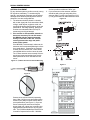
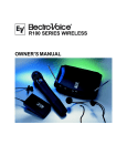
MS3000 SERIES OWNERS MANUAL MS3000 OWNERS MANUAL TABLE OF CONTENTS DESCRIPTION .......................................................................................................................................... 3 SECURE-PHASE DIVERSITY .................................................................................................................. 3 ANTENNAS .............................................................................................................................................. 3 HANDHELD TRANSMITTERS ................................................................................................................. 3 BODYPACK TRANSMITTER ................................................................................................................... 3 FRONT PANEL FEATURES DISPLAYS ................................................................................................. 3 POWER SWITCH ..................................................................................................................................... 4 SQUELCH ADJUSTMENT ....................................................................................................................... 4 REAR PANEL FEATURES ...................................................................................................................... 4 SYSTEM SET-UP AND OPERATION ................................................................................................... 4-5 RACK-MOUNT INSTALLATION .............................................................................................................. 5 ANTENNA PLACEMENT ...................................................................................................................... 5-6 COMPATIBILITY ...................................................................................................................................... 7 POTENTIAL SOURCES OF INTERFERENCE ........................................................................................ 7 SPECIFICATIONS AND FREQUENCIES ............................................................................................. 7-9 FCC INFORMATION ................................................................................................................................ 9 WARRANTY ............................................................................................................................................. 9 page 2 MS3000 OWNERS MANUAL MS3000 SERIES OWNERS MANUAL MS3000 UHF Diversity Wireless System Features Well-designed companding and audio circuitry deliver hard-wired sound quality Excellent 104 dB signal-to-noise ratio Metal chassis ½-rack space receiver with TNC antenna connectors Metering for audio level, rf and diversity channel Externally-adjustable squelch control Balanced 3-pin XLR-type and unbalanced ¼-inch audio outputs Choice of transmitters including rugged bodypack with TA4F connector for lavalier and headset microphones. Professional handheld transmitters with choice of Electro-Voice N/D767 dynamic or BK-1 condenser transducers. DESCRIPTION The Electro-Voice MS3000 is a professional quality UHF diversity wireless system that operates within the frequency range of 690 to 725 MHz (TV channels 50 55) on single custom-tuned frequencies. MS3000 Systems combine the MR3000 receiver with a choice of handheld and bodypack transmitters that allow multiple ways to achieve wireless freedom. The wide range of frequencies permit use of multiple systems simultaneously (the exact number is dependent on local conditions). The specially designed compander circuitry provides wide dynamic range with clean, accurate transient response. MR3000 receivers have ½-rack space metal chassis for ruggedness and reliability. A host of accessories are available for operational and installation flexibility. SECURE-PHASEtm DIVERSITY The MR3000 receiver utilizes patented SecurePhasetm diversity circuitry that ensures the strongest, cleanest signal possible. Unlike other diversity schemes that switch antennas or signal, SecurePhasetm utilizes the signal from both antennas at all times to increase signal strength, minimize dropouts and lower the potential for interference. If the signal from the transmitter changes phase or polarity (a common cause of dropouts), the circuit adjusts the phase angle between the two antennas receiving circuits to prevent cancellation. The two diversity lights on the front panel indicate the status of this circuit. ANTENNAS The MR3000s ½-rack space receiver has specially tuned quarter-wave antennas with TNC-type antenna connectors. These connectors are electrically and mechanically superior to the commonly used BNC connectors and are located on the rear panel of the MR3000. TNC connectors are widely used on cellular communications equipment and are readily available. Two antennas are supplied with the unit for normal use and optional accessory kits can be used to rack mount or remote-mount the antennas. Other accessories such as multi-couplers, ½-wave antennas and log periodic directional antennas are also available to meet specific installation and use requirements. HANDHELD TRANSMITTER Choice of Electro-Voice N/D767 (MSHD) N/DYM dynamic or Electro-Voice BK-1 condenser (MSHC) transducers. Special soft-touch finish and ergonomically designed handle makes holding comfortable and secure. Separate LEDs for power on and battery status for easy monitoring of operational modes. Separate power and audio mute switches for operational flexibility. Wide-range gain control allows approximately 40 dB of adjustment. Up to 10 hours of operation on a 9-volt alkaline battery. BODYPACK TRANSMITTER UHF bodypack with TA4F connector allows the user the freedom of microphone selection with easy interchangeability. Available microphones include the Electro-Voice ULM20 cardioid condenser lavalier microphone and the HM2 headset microphone. The TA4F connector allows connection of any dynamic or condenser microphone that can be biased with 5 volts DC phantom. Separate on/off and toggle mute switches for operational flexibility LED battery condition indicator gives quick indication of battery strength Up to 10 hours of operation on a 9-volt alkaline battery MR3000 FRONT PANEL FEATURES DISPLAYS The MR3000 has a number of front panel indicators to make setup and operation easier. 1. A five-segment LED meter shows audio level and is useful for setting the transmitters gain control. 2. A five-segment LED RF meter shows the strength of the incoming signal from the transmitter 3. Two LEDs indicate the action of the SecurePhasetm diversity circuitry. page 3 MS3000 OWNERS MANUAL POWER SWITCH The front-panel power switch allows the receiver to be switched on and off easily. SQUELCH ADJUSTMENT The range of the externally adjustable squelch control allows you the choice of maximizing range or lowering the potential for external interference. 5. Open the battery compartment door on the handheld transmitter or the bodypack and install a 9-volt alkaline battery (see Figures 3 and 4). 8.4 volt Ni-Cad batteries may be used but will yield noticeably shorter operational time and slightly lower performance. Figure 2 REAR PANEL FEATURES AUDIO OUTPUTS The MR3000 has both 3-pin XLR-type balanced and ¼-inch unbalanced phone jack output connectors. The line level output is adjustable with a small screwdriver (included). ANTENNA CONNECTORS The antenna inputs utilize TNC connectors that provide solid mechanical and electrical connections. POWER INPUT The MR3000 will operate from the supplied ac adapter or any other battery, filtered supply or power pack that can deliver 12 15 volts AC/DC, 300 mA. Figure 3 SYSTEM SET-UP AND OPERATION To prepare the MS3000 System for operation, you should: 1. Connect the power supply adapter to an AC outlet that will supply 105 to 125 volts AC, 60 Hz. Other power supply adapters are available for 210 240 volt, 50 60 Hz operation. Make sure that you have the correct power supply for your locality. 2. Connect the MR3000 to your audio system using the appropriate connector on the rear panel. It is preferable to use the 3-pin XLR connector since its balanced circuitry minimizes the potential for electrical interference and can be used with long cable runs. 3. Switch on the receiver with the front-panel power switch. 4. Attach either the supplied ¼-wave antennas or two externally mounted antennas to the antenna connectors on the rear panel of the MR3000. Be sure and tighten the connectors securely. If the supplied ¼-wave antennas are used, they must be oriented at a 90o angle as shown in Figure 1. Unlike other diversity wireless systems, two antennas are needed for the MS3000 to operate correctly. Figure 1 page 4 Figure 4 MS3000 OWNERS MANUAL 6. When the battery is installed, you may plug in the microphone to the bodypack or simply switch on the handheld transmitter and begin operation. 7. When the system is first operated, the gain of the transmitter should be adjusted to the vocalist or speaker who will be using it. Speak or sing as loudly as possible into the microphone. Observe the audio level meter on the receiver. Figure 5 1 SQUELCH AUDIO LEVEL:dB RF LEVEL 2 1 2 3 4 5 -20 -10 2. Align the correct rack ear or bracket with the holes on the side of the unit. Install the previously removed screws. Insert an additional screw (provided in the parts pack) into the remaining hole. Repeat this step for the opposite side of the unit. Be sure to tighten all screws securely. For double mounting of two systems, proceed as follows: DIVERSITY POWER To assemble the rack mount adapters to the unit(s) and install into a rack, proceed as follows: 1. Remove the front Phillips head screws from each side of each unit. -5 0 +3 R MR3000 Adjust the gain control on the transmitter (see Figures 2 and 4) to prevent over or under-modulation. The gain should be adjusted so that the signal peaks are no more than +0 dB and that there is at least 10 dB of audio level meter indication. 8. The squelch control on the front of the receiver may be adjusted to increase range or reduce interference. If the squelch control is being adjusted, it should be adjusted with the transmitter off. CAUTIONDECREASING SQUELCH WILL MAKE THE SYSTEM MORE SUSCEPTIBLE TO OUTSIDE INTERFERENCE! Use the small screwdriver supplied with the unit and turn the squelch control clockwise to reduce interference from noise and spurious radio signals. To best set the squelch control, turn the control counter-clockwise until you hear noise and interference and then turn it back clockwise until the noise is squelched off. This setting will give you the best balance between noise and reduced range. 9. Before using the system before an audience, it is a good idea to walk the expected use area to check for dropouts. To minimize the potential for dropouts, please observe good antenna placement. When the transmitter is turned on, the RF meter on the receiver should be illuminated in the green range to verify it is receiving a strong signal. 10. When the transmitter power switch is turned on, the red battery light will flash one time if the battery is good and has adequate strength. If the red light does not flash or stays on continuously, the battery is weak and should be replaced. 1. Align the mid-sized brackets (item #2) with the holes on the adjacent sides of each unit. 2. Install the previously removed screws. Insert an additional screw (provided in the parts pack) into the remaining holes. Tighten all screws securely. Figure 6 3. Place the two assemblies side-by-side with the mid brackets together. (The left bracket should fit above the right so that the countersinks are visible). Install 4 flat-head screws (item #5) and tighten them securely. 4. Attach the antenna connectors to the brackets. 5. Attach the supplied extension cables from the rack connectors to the antenna connections on the back of the receiver. 4. Place the assembly in to the 19-inch rack enclosure and insert 4 #10-32 x 3/8 Phillips pan head screws (supplied) in each corner of the rack ears and secure to the enclosure. Figure 7 RACK-MOUNT INSTALLATION The MR3000 is supplied with rack mounts for single and double mounting in a standard EIA 19 equipment rack (see Figure 6). For rack mounting a single unit, a long and short ear are used. For dual side-by-side mounting, use the short ears and the mid sized brackets from two MR3000s as shown. page 5 MS3000 OWNERS MANUAL ANTENNA PLACEMENT For any wireless system to perform correctly, strong RF signals are mandatory. To maximize signal strength, good antenna placement must be utilized. Although some situations prohibit perfect antenna placement, here are some guidelines: and can provide an additional 5 dB of gain 3. If you remote-mount the antennas, attention should be paid to the type and quality of the antenna cable. For cable runs longer than 25-ft (7.6 M), special low-loss cables should be used. Figure 10 1. The antennas should be placed in a location with a clear signal path to the transmitter. Walls, ceilings, metal objects, equipment racks, etc. are all signal barriers that will reduce range and performance. Generally speaking, placing the receiver at an elevated location can help increase range and signal strength. 2. If the receiver is rack-mounted, external antennas are necessary. Do not rack mount the MR3000 with the antennas mounted directly on the back of the unit. This will severely decrease the range and performance of the system. If the MR3000 is rack-mounted, make sure the antennas are front-mounted (following the directions noted above). If antennas are mounted remotely from the chassis, the ¼-wave antennas supplied with the receiver cannot be used. The ½-wave antennas are a necessity if the antennas are remote-mounted and can provide better performance when used with the rack mount. Figure 8½-Wave Antenna for Remote Mounting Figure 11 Figure 9 If antennas are remote-mounted, separating them 6 feet (1.8 M) or more and keeping them at least 2 feet (.6M) from other barriers will improve performance (see Figure 11). If you are remote mounting the antennas and require strong signal over a large area, consider using highly directional antennas such as a log-periodic. The LPA500 available from Electro-Voice is tuned for frequencies from 450 900 MHz page 6 MS3000 OWNERS MANUAL Figure 12 These cables are available as accessories (see accessories listing). 4. If multiple wireless systems are being used, a multi-coupler will minimize antenna interference. A multi-coupler has one set of antennas and distributes RF signal to multiple systems. The Electro-Voice A/P4X4 will supply antenna signal and DC power to 4 systems, eliminating 3 external power supplies and 6 antennas (Figure 12). COMPATIBILITY The receiver and transmitter must be tuned to the same frequency in order to operate together as a system. Mixing brands of wireless components, even if units have the same frequency, will not work due to differences in companding circuits. If two or more MS3000 and/or other VHF/UHF wireless systems are being used in the same location, proper frequency coordination is necessary to avoid interference. Frequency mixing and spacing must be factored along with local TV stations to determine if conflicts will result from a specific group. Contact your dealer or Electro-Voice for frequencyselection assistance if you are planning to add more wireless systems to be operated simultaneously in the same location. POTENTIAL SOURCES OF INTERFERENCE There are many potential sources of interference for your wireless system. Any electronic component that contains digital circuitry including digital signal processors (reverb/multi-effects units), electronic keyboards, digital lighting controllers, CD players and computers all emit rf energy that can adversely affect the performance of your wireless system. It is always best to place your receiver as far away from these devices as possible to minimize this potential source of interference. SYSTEM SPECIFICATIONS STANDARD FREQUENCIES (MHz) 690.100; 690.500; 691.200; 692.100; 694.200; 695.000 695.350; 695.500; 696.425; 696.725; 698.200; 699.800 700.200; 702.200; 702.600; 703.250; 704.250; 706.250 707.460; 707.850; 708.600; 709.150; 710.350; 712.250 713.900; 714.450; 715.350; 717.750; 719.050; 720.600 MR3000 RECEIVER Frequency Range RF Stability Modulation Type Type IF Bandwidth Image Rejection Squelch Audio Outputs: Mic Level: Line Level: Signal-to-Noise Ratio Receiver Sensitivity: FCC Compliance: FCC Identification: Diversity: Supplied Accessories: Size (HxWxD): 690 725 MHz 0.005% or better FM, 40 kHz nominal Double Conversion, 65.75 MHz and 10.7 MHz I.F. 230 kHz at 3dB points 65 dB or better Amplitude adjustable -20 dBV at 600 ohms 0.775 V rms at 100K ohms (max) 104 dB Less than 0.8 uV for 12 dB SINAD Notification, Part 15 B5DR307 Continuous Secure-Phasetm Diversity to maximize signal strength Two ¼-wave antennas; rack mount adapters (1 short, 1 mid, 1 long); gain adjustment screwdriver; AC power supply (120 Volt/60 Hz or 230 Volt/50 Hz); owners manual. 1.75 in x 7.5 in x 7.75 in without antennas (31.75 x 190.5 x 196.85 mm) page 7 MS3000 OWNERS MANUAL Weight: 2.06 lb/1.06 kg MSH Handheld Transmitter Power Output: Antenna: Modulation: Frequency Response: Transducer: Supplied Accessory: Battery: Approvals: FCC Identification: Size: Weight (MSHD) Weight (MSHC) MSB Bodypack Transmitter Power Output: Antenna: Modulation: TA4F Connector: Frequency Response: Microphone Input Sensitivity: DC Power: Approvals: FCC Identification: Size (HxWxD): Weight: 10 mW terminated, 50-mW maximum Internal (patented) FM, +40 kHz Deviation w/50 us pre-emphasis 50 Hz to 15,000 Hz Electro-Voice N/D767 Supercardioid (MSHD) Electro-Voice BK-1 Cardioid Electret (MSHC) Stand adapter 9 volt alkaline FCC, Part 74H Industry Canada RSS123 B5DH211 10.75 in long (27.3 cm) x 2 in (5.08 cm) max. 284 g (10 oz) without battery 246 g (9.6 oz) without battery 10 mW terminated, 50-mW maximum Permanently attached FM, +40 kHz Deviation w/50 us pre-emphasis Pin 1: Ground; Pin 2: Mic Input; Pin 3: +5 volt bias; Pin 4: +5 volt bias fed through a 3 K ohm resistor for 2-wire electrets 50 Hz to 15,000 Hz 7.8 mV for full deviation 9 volt alkaline battery FCC, Part 74H Industry Canada RSS123 B5DB108A 4.5 in x 2.6 in x 1.25 in (no antenna) (114.3 cm x 66 cm x 31.75 cm) 3.5 oz (480 grams) without battery Figure 13TA-4F Connector Wiring Pin 1 = ground Pin 2 = mic input Pin 3 = +5 volt bias Pin 4 = +5 volt bias fed through 3K resistor for 2-wire electrets Figure 13 AVAILABLE ACCESSORIES Model Part # ULM20 ULM20 CS200EX CO2EX CM-311 E3K HM2 HM1 879155 page 8 Description Electro-Voice cardioid lavalier microphone Electro-Voice cardioid lavalier microphone Electro-Voice omnidirectional lavalier Crown differoid headset microphone Electro-Voice cardioid headset microphone Electro-Voice cardioid headset microphone ULM20 windscreen MS3000 OWNERS MANUAL Model A/P4X4 CLA-5 AB-2 LPA 500 Part # 879156 358879 730131-2 730104-1 730103-1 879010 870658-5 71138000 71151025 71151050 71151075 71151100 Description ULM20 mic clip metal clip for bodypack Electro-Voice Multi-coupler for 4 systems 120-volt power supply 230-volt power supply (Euro-type plug) 230-volt power supply (UK-type plug) ¼-wave antenna with TNC connector ½-wave antenna with TNC connector Combination antenna bracket and cables Electro-Voice Log-periodic directional antenna 25' (7.62M) coax cable with TNC connectors 50' (15.24M) coax cable with TNC connectors 75' (22.86M) coax cable with TNC connectors 100' (30.4M) coax cable with TNC connectors FCC INFORMATION The Electro-Voice MR-3000 receiver is authorized under Part 15 of the Federal Communications Commission. Licensing of Electro-Voice equipment is the users responsibility and licensability depends upon the users classification, and frequency selected. Electro-Voice strongly urges the user to contact the appropriate telecommunications authority before ordering the choosing frequencies other than factory preset frequencies. The Electro-Voice MSB and MSH transmitters are Type Accepted under United States Federal Communications Commission Part 74. Licensing of Electro-Voice equipment is the users responsibility and licensability depends upon the users classification, users application, and frequency selected. Electro-Voice strongly urges the user to contact the appropriate telecommunications authority for any desired clarification. CAUTION: Any changes or modifications made to the above equipment could void the users authority to operate the equipment. WARRANTY (Limited) Electro-Voice products are guaranteed against malfunction due to defects in materials or workmanship for a specified period, as noted in the individual product-line statement(s) below, or in the individual product data sheet or owners manual, beginning with the date of original purchase. If such malfunction occurs during the specified period, the product will be repaired or replaced (at our option) without charge. The product will be returned to the customer prepaid. Exclusions and Limitations: The Limited Warranty does not apply to: (a) exterior finish or appearance; (b) certain specific described in the individual product-line statement(s) below, or in the individual product data sheet or owners manual; (c) malfunction resulting from use or operation of the product other than as specified in the product data sheet or owners manual; (d) malfunction resulting from misuse or abuse of the product; or (e) malfunction occurring at any time after repairs have been made to the product by anyone other than Electro-Voice or any of its authorized service representatives. Obtaining Warranty Service: To obtain warranty service, the customer must deliver the product, prepaid, to Electro-Voice or any of its authorized service representatives together with proof of purchase of the product in the form of a bill of sale or receipted invoice. A list of authorized service representatives is available from Electro-Voice at 600 Cecil Street, Buchanan, MI 49107 (616/695-6831 or 800/234-6831). Incidental and Consequential Damages Excluded: Product repair or replacement and return to the customer are the only remedies provided to the customer. Electro-Voice shall not be liable for any incidental or consequential damages including, without limitation, injury to persons or property or loss of use. Some states do not allow the exclusion or limitation of incidental or consequential damages so the above limitation or exclusion may not apply to you. Other Rights: This warranty gives you specific legal rights and you may also have other rights which vary from state to state. Electro-Voice Wireless Systems are guaranteed against malfunction due to defects in materials or workmanship for a period of one (1) year from the date of original purchase. The Limited Warranty does not extend to cables or cable connectors. Additional details are included in the Uniform Limited Warranty Statement. Service and repair addresses for this product: Telex Communications 8601 East Cornhusker Highway, Lincoln, Nebraska 68506 (402/467-5321) and Electro-Voice 600 Cecil Street, Buchanan, Michigan 49107 (616/695-6831 or 800/234-6831) page 9 MS3000 OWNERS MANUAL page 10 MS3000 OWNERS MANUAL page 11 600 Cecil Street, Buchanan, MI 49107 616/695-6831, 616/695-1304 Fax MANUAL - MS3000 ©Telex Communications, Inc. 1999 • Litho in U.S.A. Part Number 535427 — 9912