1
WELLS MANUFACTURING COMPANY
2 ERIK CIRCLE, P. O. Box 280
Verdi, NV 89439
Customer Service (775) 345-0444 Ext.502
fax: (775) 345-0569
www.wellsbloomfield.com
361
SERVICE
INSTRUCTIONS
for
ELECTRIC
FRYER
WFAE-30F
IMPORTANT: WELLS MFG. PROPRIETARY INFORMATION
TECHNICAL CONTENT OF THIS MANUAL IS DESIGNED FOR
USE BY QUALIFIED PROFESSIONAL TECHNICIANS ONLY
Part No. 501219 Rev. (-)
M361 110800
cps
SAFETY PROCEDURES
Knowledge of proper procedures is essential to the safe operation of electrically energized
equipment. In accordance with generally accepted product safety labeling guidelines for
potential hazards, the following signal words and symbols are used throughout this manual.
DANGER
DANGER - Danger is used to indicate the presence of a hazard which will
cause severe personal injury, death, or substantial property damage in the
event the statement is ignored.
WARNING - Warning is used to indicate the presence of a hazard which can cause
personal injury and possibly death, or major property damage, in the event the statement is ignored.
CAUTION - Caution is used to indicate the presence of a hazard which will or can cause
minor personal injury, or property damage in the event the statement is ignored.
CAUTION - Used to indicate the presence of an electrical hazard which will or can cause
personal injury, or property damage in the event the statement is ignored.
NOTE - Note is used to notify personnel of installation, operation or maintenance information
which is important, but not hazard related.
FRYER PRECAUTIONS AND GENERAL INFORMATION
1.
This fryer is intended for use to deep fry food products for human consumption. No other use
is recommended or authorized.
2.
Service technicians must be familiar with the appliance use, limitations and associated hazards.
Operating instructions and warnings must be read and understood by all service personnel.
3.
This WELLS fryer is equipped with an oil filtration system, which is designed to filter hot liquid
shortening ONLY. Water, cleaning agents or other liquids will damage the FILTER PUMP.
4.
This piece of equipment is made in the USA and, except where otherwise noted, has American
sizes on hardware.
5.
This manual supplements the Installation, Operation and Maintenance Manual (IOM) p/n 301669
for this equipment. Refer to the IOM, for normal operational procedures. Any trouble shooting
guides, component views or parts lists included in this manual are intended for use by qualified
technical personnel.
xi
TABLE OF CONTENTS
Specifications
Features and Operating Controls
Upper Control Panel
Lower Control Panel
Operation
Heating and Cooking Instructions
Troubleshooting Operational Problems
Filtering instructions
Troubleshooting Filtering Problems
Servicing Instructions
Lift Motor Assembly
Fliter Pump Assembly
Electrical Components
Service Parts list
Wiring Diagrams
1
2
4
5
6
7
8
9
10
12
14
19
20
GENERAL SPECIFICATIONS
DIMENSIONS
Wide
Deep
High
15.70”
33.25”
40.0”
ELECTRICAL
Voltage Requirement
208 VAC
240 VAC
380-415 VAC (Export)
Note: Shipped from the factory 3 phase, field convertible to single phase
Power Consumption
9,000 Watts
(Europe)
9,300 Watts
Amperage
208V 1∅
43.3 Amp
240V 1∅
37.5 Amp
208V 3∅
25.0 Amp per leg
240V 3∅
21.7 Amp per leg
NOTICE: For 208/240V supply connections use 12 ga. copper wire suitable for
at least 75º Centigrade.
380-415V 3∅
L1 14.3 Amp, L2 & L3 13.0 Amp
See European Operations Manual p/n 301796AS for 380-425V supply wiring
connection requirements.
1
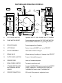
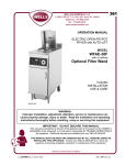
FEATURES AND OPERATING CONTROLS
SIDE VIEW
BACK VIEW
C
FRONT VIEW
D
S
M
A
N
E
O
F
B
J
G
P
H
K
Q
I
L
R
A.
LIFT CRADLE MOTOR
Operates the LIFT ROD / RAISES the LIFT CRADLE
B.
PUMP MOTOR RESET
Protects against overload of FILTER PUMP MOTOR
Must be RESET MANUALLY by pushing red button
C.
FRYPOT COVER
Protects against hot oil splatter
D.
LIFT CRADLE
Raises / lowers BASKET into / out of FRYPOT
E.
FRYPOT ASSEMBLY
Heats and contains cooking oil
F.
DRAIN VALVE
Allows draining of cooking oil / cleanser from FRYPOT
G.
FILTER PUMP & MOTOR
Pumps oil during filtering cycle
H.
POWER CORD
Hook-up for electrical power
I.
REAR (FIXED) CASTER
For ease in positioning unit
J.
LOWER CONTROL BOX
and TERMINAL BLOCK
COVER
Contains CONTACTOR, and connections for POWER
CORD, ELEMENTS, TEMPERATURE CONTROL
THERMOSTAT and HI-LIMIT THERMOSTAT
K.
POWER CONNECTION
90ºconduit fitting required, angled as shown.
2
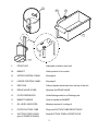
T
U
V
R
D
L.
FRONT LEG
Adjustable to attain a level unit
M.
BASKET
Holds product to be cooked
N.
UPPER CONTROL PANEL
See page 4
O.
LOWER CONTROL PANEL
See page 5
P.
DRIP PAN
Collects liquids which drain from the top of the unit
Q.
DRAIN VALVE LEVER
Operates the DRAIN VALVE
R.
FILTER RESERVOIR
Holds filtering media for oil filtering cycle
S.
BASKET HANDLE
Used to handle hot BASKET
T.
OIL LEVEL INDICATOR
Measure amount of cooking oil
U.
FILTER SUCTION TUBE
Plugs into SUCTION TUBE RECEPTACLE
V.
SUCTION TUBE O-RING
(plus 3 SPARE O-RINGS)
Seals SUCTION TUBE to RECEPTACLE
3
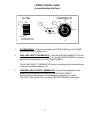
UPPER CONTROL PANEL
FRYER
OFF
FILTER
1. POWER SWITCH: FRYER position energizes TEMPERATURE CONTROL
THERMOSTAT and TIMER. FILTER position energizes FILTER SWITCH. OFF
position de-energizes HEATING ELEMENT, TIMER and FILTER SWITCH.
2. POWER LIGHT: Is ON when the POWER SWITCH is in FRYER position.
3. HEAT LIGHT: Is ON when the heating element is energized. This light will cycle ON
and OFF as the TEMPERATURE CONTROL THERMOSTAT cycles.
4. COOK LIGHT: Is ON when the TIMER is ON ( i.e. any time other than 0, and the
TIMER BUTTON has been pressed ).
5. TIMER: Is ON when the TIMER BUTTON is pushed. The timer displays the set time
and automatically resets to the last set time after each cooking cycle. Controls the
function of the BASKET LIFT.
6. BUZZER SWITCH: Controls the buzzer circuit. When the switch is in the ON
position, the BUZZER sounds when the BASKET LIFT is raised, the buzzer continues
to sound until silenced by turning the BUZZER SWITCH OFF.
7. BUZZER LIGHT: Is ON when the BUZZER SWITCH is in the ON position.
4
LOWER CONTROL PANEL
(Located behind the Door)
THERMOSTAT
FILTER
325
1
ON
3
2
HI-LIMIT
RESET
OFF
CAUTION
FRYER MUST BE OFF
BEFORE USING FILTER
300
350
250
375
275
ºF
1.
FILTER SWITCH: ON position energizes the FILTER PUMP when the POWER
SWITCH is in the FILTER position.
2.
HIGH LIMIT SAFETY THERMOSTAT: Turns the HEATING ELEMENT OFF if the
cooking oil temperature exceeds 425º F, or if the HEATING ELEMENT is energized
without oil covering the top of the HEATING ELEMENT.
The HI-LIMIT SAFETY THERMOSTAT is reset by pushing the Red button after the
cooking oil has been allowed to cool.
3.
TEMPERATURE CONTROL THERMOSTAT: Controls the temperature of the
cooking oil by energizing / de-energizing the HEATING ELEMENT.
Set the Pointer to the desired cooking temperature marked on the panel.
The HEAT LIGHT will be ON any time the HEATING ELEMENT is energized.
5
OPERATION
HEATING INSTRUCTIONS
IMPORTANT: Never press the POWER SWITCH to FRYER unless the heating
elements are covered with liquid shortening. Check shortening level marker inside
the cooking basket for proper shortening level.
NOTE: The fryer is designed to be used with LIQUID SHORTENING only.
Lard and solid shortening will solidify in the filter pump, causing pump failure.
1.
Set the TEMPERATURE CONTROL THERMOSTAT to 350º F.
2.
Press POWER SWITCH to FRYER position. The contactor will close and the HEATING
ELEMENT will start heating the shortening. The HEAT LIGHT will turn ON any time
the TEMPERATURE CONTROL THERMOSTAT is calling for heat and the HEATING
ELEMENT is energized. NOTE: The first time the HEAT LIGHT goes out, the fryer is
ready to begin cooking.
COOKING INSTRUCTIONS
1.
Load product into the BASKET. Using the BASKET HANDLE, set the BASKET on the
LIFT CRADLE. Remove the BASKET HANDLE.
IMPORTANT: Different products contain different amounts of moisture, which will
cause the hot oil to foam. Determining the maximum safe load size that will prevent
hazardous overflow and splatter of hot oil. This can be accomplished by starting
with a small load, and gradually increasing the load size until the maximum load
which can be cooked without the oil foaming over the top of the frypot is reached.
2.
Set the TIMER for the time required to cook the particular product weight. Press the red
button in the center of the TIMER. The CRADLE LIFT will lower and the TIMER will start
counting-down. The COOK LIGHT will turn ON when the cradle is fully lowered.
Allow the FRYPOT COVER to lower over the FRYPOT.
Turn the BUZZER SWITCH to ON.
3.
At the completion of the timed cycle, the TIMER will reach 0, the BUZZER will sound and
the CRADLE LIFT will raise.
The BASKET and the cooked product will be hot.
Contact with hot cooked product can cause serious injury.
4.
Use the BASKET HANDLE to remove the BASKET and dump the cooked product into a
suitable tray or container.
6
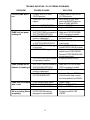
TROUBLE SHOOTING - OPERATING PROBLEMS
PROBLEM
POWER LIGHT not lit
(Fryer not operating)
POSSIBLE CAUSE
SOLUTION
POWER SWITCH not
in FRYER position
Circuit breaker OFF or tripped
Service wiring problem
POWER LIGHT defective
Press POWER SWITCH
to FRYER position
Reset circuit breaker
Correct service wiring
Replace LIGHT
TEMPERATURE CONTROL
THERMOSTAT set too low
TEMPERATURE CONTROL
THERMOSTAT defective
HI-LIMIT THERMOSTAT
TRIPPED
HEAT LIGHT defective
Set THERMOSTAT to
350ºF
Replace THERMOSTAT
COOK LIGHT not lit
(CRADLE LIFT raised)
(CRADLE LIFT lowered)
TIMER not energized
COOK LIGHT defective
Set and energize TIMER only
when ready to cook
Replace LIGHT
BUZZER LIGHT not lit
BUZZER SWITCH in OFF pos.
BUZZER LIGHT defective
Turn SWITCH ON
Replace LIGHT
BUZZER does not
sound
BUZZER SWITCH in OFF pos.
BUZZER defective
BUZZER SWITCH defective
Turn SWITCH ON
Replace BUZZER
Replace SWITCH
CRADLE LIFT won’t
lower
TIMER not energized
TIMER defective
LIFT MOTOR defective
MICROSWITCH misadjusted
Set and energize TIMER only
when ready to cook
Replace TIMER
Replace LIFT MOTOR
Adjust MICROSWITCH
CRADLE LIFT won’t
raise
TIMER has time remaining
LIFT CRADLE not properly
assembled to LIFT ROD
TIMER defective
LIFT MOTOR defective
MICROSWITCH misadjusted
ACTUATOR or LIFT CRADLE
damaged
Allow TIMER to drop to 0
Install white plastic pivot over
end of lift rod (see page 3)
Replace TIMER
Replace LIFT MOTOR
Adjust MICROSWITCH
Repair / replace damaged
components
FRYPOT COVER
won’t lower
COVER leaned back too far
HINGE(S) damaged / dirty
or misaligned
Rest COVER on LIFT CRADLE
Repair / clean / align hinges
(Fryer operating norm.)
HEAT LIGHT not lit
(POWER LIGHT lit)
(Cooking oil cold)
POWER LIGHT not lit
(Cooking oil cold)
(Cooking oil hot)
7
Allow oil to cool
Reset HI-LIMIT
Replace LIGHT
OIL FILTERING INSTRUCTIONS
DANGER
OIL MUST BE FILTERED WHILE HOT (300ºF AND HIGHER)
Contact with hot oil can cause serious injury including death.
Always wear protective clothing and insulated gloves when
filtering the cooking oil.
1.
Refer to the Installation, Operation and Maintenance Manual (p/n 301669) for complete operating
instructions for the filter system.
2.
The cooking oil must be hot (minimum of 300º F.) in order to filter properly. Cold oil will not flow
through the filter paper. Place the POWER SWITCH to the FILTER position.
3.
Insure that the FILTER SCREEN, FILTER PAPER,
and FILTER PAPER HOLDER are properly installed
in the FILTER RESERVOIR. Be sure the FILTER
SCREEN is installed under the FILTER PAPER.
NOTE: If the filter pump is not operating before
the DRAIN VALVE is opened, damage to the
FILTER PAPER will occur, resulting in the oil
flowing but not filtering.
DO NOT run the pump for more than 10 sec.
without oil flowing.
4.
Open the DRAIN VALVE. The WOOD DOWEL
may be needed to unplug the drain hole.
5.
While draining the oil, pour the FILTER
POWDER into the oil at the point where it
is being drawn down the drain.
6.
After all the oil has drained from the
FRYPOT, use the HI-TEMP BRUSH to
push breading crumbs and other debris
down the drain.
FILTER
PAPER
HOLDER
FILTER
PAPER
FILTER
SCREEN
(clip inserts into
drain opening)
“O” RING
FILTER
RESERVOIR
NOTE: use caution not to damage the two small CAPILLARY TUBES toward the front of the
HEATING ELEMENT.
7.
After 3 - 4 minutes of oil circulation, close the DRAIN VALVE and allow the FRYPOT to fill with the
freshly filtered oil. When all the oil has returned to the FRYPOT, turn OFF the FILTER SWITCH.
Turn the POWER SWITCH to the OFF position until starting to use the fryer again.
7.
Allow the FILTER RESERVOIR to cool before servicing. Refer to the IOM Manual (p/n 301669)for
complete FILTER RESERVOIR maintenance instructions.
NOTE: Refrain from using soap in the FRYPOT or FILTER RESERVOIR. Soap residue
will cause the cooking oil to breakdown rapidly.
8
TROUBLE SHOOTING - OIL FILTERING PROBLEMS
PROBLEM
FILTER PUMP won’t
run
POSSIBLE CAUSE
POWER SWITCH not in
FILTER position
PUMP MOTOR OVERLOAD
tripped
Defective FILTER SWITCH
Defective POWER SWITCH
PUMP will not pump
cooking oil
SUCTION TUBE not seated in
SUCTION RECEPTACLE
SUCTION TUBE O-RING
missing or damaged
Damaged SUCTION TUBE
or SUCTION RECEPTACLE
PUMP CHECK VALVE plugged
or reversed
FILTER PAPER clogged
FILTER SCREEN not installed
or improperly installed
PUMP pumps lots of
bubbles in cooking oil
SOLUTION
Press POWER SWITCH to
FILTER position
Allow motor to cool, then
press red RESET button on
back of PUMP MOTOR
Replace SWITCH
Replace SWITCH
Make sure FILTER RESERVOIR is properly installed
Replace O-RING with one of
the three spares
Replace damaged
components
Clean CHECK VALVE
Install CHECK VALVE properly
Scrape crumbs and other
debris from FILTER PAPER
Service FILTER RESERVOIR
at next opportunity
Properly install SCREEN
SUCTION TUBE not seated in
SUCTION RECEPTACLE
SUCTION TUBE O-RING
missing or damaged
Insufficient oil entering or in
FILTER RESERVOIR
Make sure FILTER RESERVOIR is properly installed
Replace O-RING
PUMP MOTOR tripped
won’t reset
PUMP jammed with debris
Defective PUMP HEAD
Defective PUMP MOTOR
Unjam PUMP
Replace PUMP HEAD
Replace MOTOR only
Oil is not being fltered
completely
FILTER PAPER missing,
damaged or mis-installed
Properly install FILTER
PAPER
9
Incrementally open DRAIN
VALVE and/or clear crumbs
and other debris from DRAIN
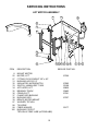
SERVICING INSTRUCTIONS
LIFT MOTOR ASSEMBLY
8
97
25
38
FRYPOT
37
39
100
X
36
37
38
ITEM
8
25
27
31
32
33
34
35
36
37
38
39
97
98
99
100
39 35 34 33 32 98
DESCRIPTION
31 99
SERVICE PART NO.
MOUNT, MOTOR
MOTOR, LIFT
FITTING, FLEX CONDUIT 3/8”x 90º
BUSHING, HEYCO 1/2”
INSULATOR, MICROSWITCH
SWITCH, UNIMAX REF 71630
ACTUATOR, LIFT
BEARING, TRACK
CRADLE LIFT
CLAMP, ROD BUSHING
BUSHING, ROD
BRACE, MOTOR MOUNT
WASHER, TEFLON
TIE-WRAP
FIBER WASHER
BUSHING, FRYPOT
TEFLON HI-TEMP LUBE (ACCROLUBE)
10
67366
67085
50198
69826
50483
67361
67357
50177
27
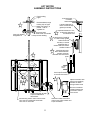
LIFT MOTOR
ASSEMBLY INSTRUCTIONS
Frypot bushing
Frypot
10-32 truss head:
nut inside /
head outside
Rod assembles through
bushing in lip of frypot
Make sure bushing is
present. Lube w/
vegetable oil
A
Lube lift cradle side of
brace w/ Teflon hi-temp
grease (Accrolube)
Adjust this clearance to .05”,
or about the thickness of
B
a matchbook cover
8-32 truss head:
head inside / nut outside
Clamp secures bushing
Lube channel of cradle lift
w/ Teflon hi-temp grease
Roller should ride
smoothly in channel
Assemble roller to
actuator with lock washer
and Red Loctite
LONG END OF ROD
C
Assemble with white
Teflon washer between
actuator and motor
Assemble with cam toward
motor
D
A
B
C
CAM
Lube rod & bushing
w/vegetable oil
MOTOR
SHAFT
LONG ARM
OF ACTUATOR
Use Purple Threadlock
on actuator set screws
E
E
D
Secure wiring with tie wrap
to prevent interference
with actuator
Drill mounting holes in motor case to 13/64“
Use 10-32 ss countersunk screws with
Tenz nuts on motor side
11
Adjust microswitch such
that the cam positively
actuates the switch
during its entire travel
Be sure to install the
insulator between the
microswitch and the
motor mount
Assemble conduit connector to
motor mount w/ fiber washer and
Purple Threadlock
FILTER PUMP ASSEMBLY
27
87
7M
7P
88
89
94
90
93
95
86
84
7B
82
80
ITEM DESCRIPTION
7B
7M
7P
27
80
82
84
86
87
88
89
90
93
94
95
SERVICE PART NO.
BRACKET, MOTOR STABILIZING
MOTOR, FILT 1P 125/230V 50/60
PUMP, FILTER
FITTING, FLEX CONDUIT 3/8”x 90º
SUCTION LINE FITTING
ADAPTER 1/2”NPT FEMALE x 15/16M FLARE
FLEX LINE, SUCTION SS 3/4”OD x 16.5”
ADAPTER 1/2”NPT MALE x 15/16M FLARE
FIBER WASHER
BUSHING, REDUCER 1/2”NPT x 3/8”NPT
NIPPLE, 3/8” x CLOSE
ADAPTER, 3/8” FPT FEMALE x 3/4M FLARE
FLEX LINE, PRESSURE SS .6”OD x 9.5”
CHECK VALVE
ADAPTER, 1/2” NPT FEMALE x 3/4M FLARE
12
501205
501231
66720
502287
50177
502289
66692
FILTER PUMP / MOTOR
ASSEMBLY INSTRUCTIONS
F APPLY PIPE SEALANT TAPE (PST) TO
MALE PIPE THREADS. DO NOT APPLY
ANY TYPE OF PIPE COMPOUND OR TAPE
AT FLARE FITTINGS.
FR
YP
OT
J
F
J
ADAPTER
1/2“FPT x
3/4“M FLARE
C
SUCTION
FITTING
ASSEMBLE FLARE FITTINGS FINGER TIGHT
WITHOUT ANY TYPE OF PIPE COMPOUND.
THEN, TORQUE FLARE FITTING:
DISCHARGE TUBE TO 25 ft-lb
SUCTION TUBE TO 33 ft-lb.
ALWAYS USE A BACKUP WRENCH ON THE
MALE FLARE FITTING.
DO NOT ALLOW CORRUGATED PIPE TO
TWIST DURING ASSEMBLY.
F
J
C
C DO NOT BEND CORRUGATED TUBE
FLEX HOSE
.75“x 16.5”
WITHIN 1“ OF ANY FITTING.
J
C
FLEX HOSE
.6“OD x 9.5”
F
F
F F
ADAPTER
3/8“FPT x 3/4”M FLARE
CHECK VALVE
ARROW POINTS
TOWARD FRYPOT
ADAPTER
1/2“FPT x
15/16“M FLARE
J
C
ADAPTER
1/2“MPT x 15/16”M FLARE
PUMP /
MOTOR
NIPPLE 3/8“x CLOSE
BUSHING 3/8“x 1/2”
CAUTION: New style motor is a dual voltage rated unit, and must be field
wired to match the electrical service supply voltage. Motor may be shipped
wired for either 230V or 125V. Verify the supply voltage and the motor
voltage configuration. If necessary, rewire motor, at the terminal block in the
end of the motor, per the table shown below. Also, see diagram on motor.
WARNING: Failure to correctly wire the motor will result in permanent
damage to the pump motor.
M
O
T
O
R
T
E
R
M
I
N
A
L
S
125V
2
1
3
5
1 (LINE)
2
4
3
4
5
6
6 (LINE)
YELLOW / BLACK
BLUE
BLUE
(UNUSED)
BLACK
BROWN
ORANGE
WHITE
YELLOW
13
230V
1(LINE)
2
3
4
5
6 (LINE)
YELLOW / BLACK
BLUE
BLUE
BROWN
BLACK
WHITE
ORANGE
YELLOW
ELECTRICAL COMPONENTS
21
58
22
FRYPOT
63P
62A
62
UPPER CONTROL
PANEL
66
75
63B
76
74a
74b
INSIDE LOWER
CONTROL PANEL
LOWER CONTROL PANEL
51
57
56
14
FRYPOT ELECTRICAL
ITEM DESCRIPTION
21
22
58
SERVICE PART NO.
ELEMENT, HEATING 208V 9000W
ELEMENT, HEATING 240V 9000W
(NOTE: ELEMENTS INCLUDE GASKET
PLUS INSTALLATION INSTRUCTIONS)
GASKET, ELEMENT
SAFETY CLAMP, THERMO BULB
69275
69276
69964
62504
UPPER CONTROL PANEL ELECTRICAL
ITEM DESCRIPTION
62
62A
63
63A
66
SERVICE PART NO.
INDICATOR LIGHT, AMBER
BUZZER
POWER SWITCH, FRYER-OFF-FILTER
SWITCH, BUZZER CIRCUIT
TIMER
50516
64834
64052
65651
68469
LOWER CONTROL PANEL ELECTRICAL
ITEM DESCRIPTION
SERVICE PART NO.
51
56
57
SWITCH, FILTER
THERMOSTAT, TEMP CONTROL
THERMOSTAT, HI-LIMIT
(NOTE: THERMOSTATS INCLUDE CAPILLARY
SEALS, GREEN GASKET PLUS INSTALLATION
INSTRUCTIONS)
74a TERMINAL BLOCK, 3 POLE. 208/240V
74b TERMINAL BLOCK, 4 POLE (EXPORT)
75 CONTACTOR, 3P, 40A, 208V
CONTACTOR, 3P, 40A, 240V
76 LUG, GROUNDING, SOLDERLESS
15
61907
66688
66663
57465
50412
57779
57780
-
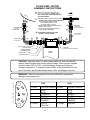
1/4" ("Gortex") GASKET INSTALLATION PROCEDURE
CAUTION: Exposed electrical circuits.
Disconnect electrical power before attempting to replace
heating elements or thermostats.
The drawings below show top view of the Gortex Gasket and Belleville Washer installation
and nut tightening sequence.
STEP 1.
STEP 2.
STEP 3.
STEP 4.
STEP 5.
STEP 6.
Install the 1/4" Gortex gasket (p/n 66864) over the element studs.
DO NOT USE RTV! Insert the element through the frypot, element and
gasket on the inside of the frypot, and studs through the appropriate holes.
Install four 1/4" Belleville washers with the high center away from the frypot,
as shown in the drawing (4 places).
Install four nuts finger tight.
Using a torque wrench, tighten all four nuts 1/2 turn at a time. Working in a
cross pattern, tightening each nut in sequence until a uniform reading of
70 inch-pounds is achieved on all four nuts.
Wait 2 minutes and re-torque all four nuts to 70 inch-pounds.
Wait an additional two minutes and re-torque all four nuts to a uniform
70 inch-pounds.
TOP VIEW
Element (ref)
Frypot (ref)
FRYPOT ELEMENT
NUT TIGHTENING SEQUENCE
1
ELEMENT GASKET
P/N
49964
p/n 69964
See step 1
BELLEVILLE WASHER
P/N
49965
p/n 69965
See step 2
NOTE orientation
to nut, 2 places
3
2
GASKET BEHIND
VIEW FROM FRONT OF UNIT
16
4
OUTSIDE OF FRYPOT
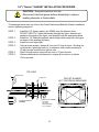
CAPILLARY COMPRESSION FITTING
1
INSIDE OF FRYPOT
2 GREEN GASKET
NOTE: FRAGILE
FEED-THRU
BUSHING
4 LOCK NUT, 17mm
5
COMPRESSION
NUT, 10mm
WASHER
CAPILLARY
3
BLACK OIL SEAL
PART OF THERMOSTAT
CAPILLARY
BELLEVILLE WASHER
(p/n 69962)
1.
Insert the feed-thru bushing through the green gasket, and insert both through the frypot
wall. Slide the Belleville washer over the protruding threads of the bushing, with the high
centerofthe w asheraway from the frypot. Thread the locknut onto the bushing and
tighten. Torque the lock nut to 30 inch pounds.
Please Note: The 17mm. hex head feed thru bushing pictured at the left of the drawing
must not be rotated during the assembly procedure. Always support the bushing with a
box wrench while tightening the assembly to avoid damage to the green gasket.
2.
Slip the bulb of the capillary tube through the bushing. Mount the bulb to the center
portion of the element with safety clamps, positioning the clamps within 3/8”of the ends of
the widest part of the bulb. Route the capillary tube alongside of the element, but out of
the way of cleaning brushes, etc. Secure the capillary tube near the frypot end of the
element with a safety clamp.
Seat the washers and oil seal into the bushing. Insert the compresson nut into the
bushing, and torque to 30 - 40 inch pounds.
NOTE: Use care to not twist or kink the capillary.
TEMPERATURE
CONTROL BULB
RIGHT SIDE
(HI-LIMIT BULB
LEFT SIDE)
CLIP
SAFETY CLAMP
HOLDS BULB
CLEAR OF
ELEMENT
CLIP
3/8“
max.
BULB
3.
3/8“
max.
BULB
TWO CLAMPS
HOLD BULB
ONE CLAMP HOLDS
CAPILLARY
17
PLACE CLAMPS WITHIN 3/8“
OF THE ENDS (WIDE PORTION)
OF BULB
LOWER CONTROL BOX
(Located behind Lower Control Panel)
CAUTION: Exposed electrical circuits
Disconnect electrical power before opening the TERMINAL
BLOCK COVER [J], or the CONTROL BOX COVER [N].
1.
TERMINAL BLOCK: Used to connect power source
wires to Fryer. (Behind Terminal Block Cover [J] ).
2.
HI - LIMIT CONTACTOR: Energized any time
POWER SWITCH is in the FRYER position and the
HI-LIMIT THERMOSTAT is within its normal range.
3.
GROUND LUG: To connect the building EARTH
GROUND wire to equipment (Fryer) CHASSIS
GROUND. (Behind Terminal Block Cover [J] ).
4.
BUSHING, HI - LIMIT: Seals the HI-LIMIT
THERMOSTAT capillary tube to the frypot.
5.
HEATING ELEMENT: Heats the cooking oil. The
heating element is turned ON and OFF by the
TEMPERATURE CONTROL THERMOSTAT.
6.
BUSHING, TEMPERATURE CONTROL: Seals the TEMPERATURE CONTROL THERMOSTAT capillary
tube to the frypot.
FIELD WIRING INSTALLATION AND INSPECTION INSTRUCTIONS
1.
Remove TERMINAL BLOCK COVER marked REMOVE THIS COVER FOR TERMINAL BLOCK.
2.
Supply wires must be attached to the TERMINAL BLOCK terminals marked L1, L2, and L3.
Green GROUND wire must be attached to the GROUND LUG marked “
”.
3.
Use a 90º conduit fitting/strain relief of the appropriate size. Secure the fitting to the rear of the LOWER
CONTROL BOX using the provided knockout. The fitting must angle DOWN.
4.
Supply wires must be routed and secured away from the FRYPOT, FILTER MOTOR and tubing/plumbing.
18
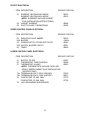
SERVICE PARTS LIST
ITEM#
DESCRIPTION
SERVICE PART NO.
ELECTRICAL
7M
21
MOTOR FOR FILTER PUMP
ELEMENT, 208V 9000W
ELEMENT, 240V 9000W
22 GASKET KIT, ELEMENT
25 MOTOR, LIFT
32 INSULATOR, MICRO SWITCH
33 MICRO SWITCH, TIMER
51 SWITCH, ROCKER, FILTER PUMP
52 KNOB ASSEMBLY, TEMP CONTROL
57 THERMOSTAT, HI-LIMIT
56 THERMOSTAT, TEMPERATURE CONTROL
62 LIGHT, SIGNAL AMBER
62A BUZZER, 240V
63 SWITCH, POWER, FRYER-OFF-FILTER
63A SWITCH, BUZZER
66 TIMER, 40MIN, 240V 60HZ
74 TERMINAL BLOCK
75 CONTACTOR, 3P, 208V 40A
CONTACTOR, 3P, 240V 40A
501205
69275
66276
66863
67366
67085
50198
67052
69688
66663
66688
50516
64834
69550
68479
50412
57779
57780
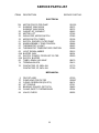
MECHANICAL
2
7P
16
20
35
58
94
FRYPOT ASSY
PUMP HEAD FOR FILTER
O-RING, RESERVIOR (PK OF 5)
LIFT CRADLE
BEARING, ROLLER (SET OF 6)
CLAMP, SAFETY THERMO BULB
VALVE, CHECK
19
67339
500567
66474
67361
50483
62504
66692
20
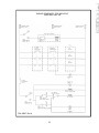
WIRING DIAGRAM FOR WFAE-30F
208V AND 240V 1Ø
P/N 49720
WIRING SCHEMATIC FOR WFAE-30F
208V AND 240V 1Ø
P/N 49567 Rev.A
21
22
WIRING DIAGRAM FOR WFAE-30F
208V AND 240V 3Ø
P/N 49721
WIRING SCHEMATIC FOR WFAE-30F
208V AND 240V 3Ø
P/N 49747
23
IMPORTANT: WELLS MFG. PROPRIETARY INFORMATION
TECHNICAL CONTENT OF THIS MANUAL IS DESIGNED FOR
USE BY QUALIFIED PROFESSIONAL TECHNICIANS ONLY
WELLS MANUFACTURING COMPANY
2 ERIK CIRCLE, P. O. Box 280
Verdi, NV 89439
Service Parts Dept. (888) 492-2782
fax: (888) 492-2783
[email protected]