1
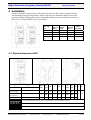
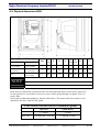
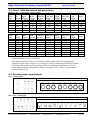
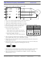
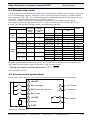
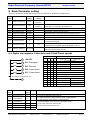
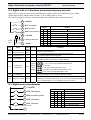
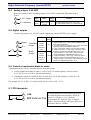
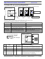
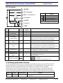
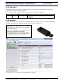
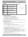
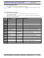
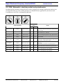
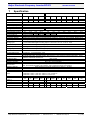
Beijer Electronic Frequency Inverter BFI-E2 1 KI00299 2012-05 Start-up document This document is a simple start-up guide describing basic functionality of the drive BFIE2. Detailed explanations are to be read in User Manual BFI-E2. This manual is attached with the drive itself but also possible to download from www.beijer.se/no/dk/fi . 2 Important Safety Information Please read the IMPORTANT SAFETY INFORMATION below, and all Warning and Caution information elsewhere. Danger : Indicates a risk of electric shock, which, if not avoided, could result in damage to the equipment and possible injury or death. Danger : Indicates a potentially hazardous situation other than electrical, which if not avoided, could result in damage to property. This variable speed drive product is intended for professional incorporation into complete equipment or systems as part of a fixed installation. If installed incorrectly it may present a safety hazard. The BFI uses high voltages and currents, carries a high level of stored electrical energy, and is used to control mechanical plant that may cause injury. Close attention is required to system design and electrical installation to avoid hazards in either normal operation or in the event of equipment malfunction. Only qualified electricians are allowed to install and maintain this product. System design, installation, commissioning and maintenance must be carried out only by personnel who have the necessary training and experience. They must carefully read this safety information and the instructions in this Guide and follow all information regarding transport, storage, installation and use of the BFI, including the specified environmental limitations. Do not perform any flash test or voltage withstand test on the BFI. Any electrical measurements required should be carried out with the BFI disconnected. Electric shock hazard! Disconnect and ISOLATE the BFI before attempting any work on it. High voltages are present at the terminals and within the drive for up to 10 minutes after disconnection of the electrical supply. Always ensure by using a suitable multimeter that no voltage is present on any drive power terminals prior to commencing any work. Where supply to the drive is through a plug and socket connector, do not disconnect until 10 minutes have elapsed after turning off the supply. Ensure correct earthing connections. The earth cable must be sufficient to carry the maximum supply fault current which normally will be limited by the fuses or MCB. Suitably rated fuses or MCB should be fitted in the mains supply to the drive, according to any local legislation or codes. Do not carry out any work on the drive control cables whilst power is applied to the drive or to the external control circuits. Within the European Union, all machinery in which this product is used must comply with Directive 98/37/EC, Safety of Machinery. In particular, the machine manufacturer is responsible for providing a main switch and ensuring the electrical equipment complies with EN60204-1. The level of integrity offered by the BFI control input functions – for example stop/start, forward/reverse and maximum speed is not sufficient for use in safety-critical applications without independent channels of protection. All applications where malfunction could cause injury or loss of life must be subject to a risk assessment and further protection provided where needed. The driven motor can start at power up if the enable input signal is present. The STOP function does not remove potentially lethal high voltages. ISOLATE the drive and wait 10 minutes before starting any work on it. Never carry out any work on the Drive, Motor or Motor cable whilst the input power is still applied. The BFI can be programmed to operate the driven motor at speeds above or below the speed achieved when connecting the motor directly to the mains supply. Obtain confirmation from the manufacturers of the motor and the driven machine about suitability for operation over the intended speed range prior to machine start up. Do not activate the automatic fault reset function on any systems whereby this may cause a potentially dangerous situation. The BFI has an Ingress Protection rating of IP20 or IP66 depending on the model. IP20 units must be installed in a suitable enclosure. When mounting the drive, ensure that sufficient cooling is provided. Do not carry out drilling operations with the drive in place, dust and swarf from drilling may lead to damage. BFI are intended for indoor use only. The entry of conductive or flammable foreign bodies should be prevented. Flammable material should not be placed close to the drive Relative humidity must be less than 95% (non-condensing). Ensure that the supply voltage, frequency and no. of phases (1 or 3 phase) correspond to the rating of the BFI as delivered. Never connect the mains power supply to the Output terminals U, V, W. Do not install any type of automatic switchgear between the drive and the motor Wherever control cabling is close to power cabling, maintain a minimum separation of 100 mm and arrange crossings at 90 degrees Ensure that all terminals are tightened to the appropriate torque setting Do not attempt to carry out any repair of the BFI. In the case of suspected fault or malfunction, contact your local Beijer Electronics office for further assistance. Sida 1 (18) Beijer Electronics Automation AB ett företag inom Beijer Electronics-koncernen Huvudkontor (styrelsens säte) Box 426 201 24 MALMÖ Telefon 040-35 86 00 Telefax 040-93 23 01 Krangatan 4A Regionkontor Box 326 192 30 SOLLENTUNA Telefon 08-626 04 20 Telefax 08-754 88 51 Bergkällavägen 32 Orgnr 556701-3965 Momsregnr SE556701-3965-01 Regionkontor Marieholmsgatan 10B 415 02 GÖTEBORG Telefon 031-707 25 50 Telefax 031-707 25 53 Försäljningskontor Jönköping 036-12 89 40 Mariestad 08-626 04 37 Luleå 0920-23 07 50 Internet www.beijer.se E-post [email protected] Beijer Electronic Frequency Inverter BFI-E2 KI00299 2012-05 3 Contents 1 START-UP DOCUMENT ............................................................................................................................................1 2 IMPORTANT SAFETY INFORMATION.................................................................................................................1 3 CONTENTS...................................................................................................................................................................2 4 INSTALLATION ..........................................................................................................................................................3 4.1 4.2 4.3 4.4 4.5 4.6 5 BASIC PARAMETER SETTING ...............................................................................................................................8 5.1 5.2 5.3 5.4 5.5 5.6 5.7 5.8 5.9 5.10 5.11 5.12 6 PHYSICAL DIMENSIONS IP20 .......................................................................................................................................3 PHYSICAL DIMENSIONS IP66 .......................................................................................................................................4 FUSES, CABLE DIMENSIONS AND POWER LOSES ...........................................................................................................5 OVERVIEW POWER INPUT/OUTPUTS .............................................................................................................................5 EXTERNAL BRAKE RESISTOR .......................................................................................................................................7 OVERVIEW CONTROL INPUTS/OUTPUTS .......................................................................................................................7 DIGITAL START SIGNAL IN 2 DIRECTIONS AND 4 FIXED PRESET SPEEDS .......................................................................8 DIGITAL START IN 2 DIRECTIONS AND ANALOG FREQUENCY SET POINT .......................................................................9 DIGITAL MOTOR POTENTIOMETER ...............................................................................................................................9 ANALOG OUTPUT, 0-10 VDC ....................................................................................................................................10 DIGITAL OUTPUTS .....................................................................................................................................................10 CONTROL OF MECHANICAL BRAKE IN MOTOR ............................................................................................................10 PTC-THERMISTOR .....................................................................................................................................................10 MODBUS RTU AND CONTROL FROM MITSUBISHI PLC ..............................................................................................11 PI-CONTROL ..............................................................................................................................................................12 ENERGY OPTIMISATION FUNCTION ............................................................................................................................12 SPIN START ................................................................................................................................................................13 OPTISTICK .................................................................................................................................................................13 KEYPAD......................................................................................................................................................................14 6.1 6.2 6.3 6.4 6.5 CHANGING PARAMETERS ...........................................................................................................................................14 RUN MOTOR FROM KEYPAD ......................................................................................................................................14 FACTORYSETTING OF DRIVE......................................................................................................................................15 MONITORING FROM KEYPAD .....................................................................................................................................15 IP66, MAINSWITCH, START/STOP SWITCH AND POTENTIOMETER ...............................................................................16 7 SPECIFICATION .......................................................................................................................................................17 8 WARNING AND ALARM CODES ..........................................................................................................................18 Beijer Electronics Automation AB Tel 040-35 86 00 Fax 040-93 23 01 Internet www.beijer.se 2 (18) Beijer Electronic Frequency Inverter BFI-E2 KI00299 2012-05 4 Installation The drive should be mounted in a vertical position only on a flat, flame resistant vibration free mounting using the integral holes. IP66 is allowed to be mounted outdoors but it must be protected from sunlight and it also recommended having a roof to avoid snow directly on drive. See User Manual BFI-E2 for more details. Drive IPclass and Size IP20, size 1 IP20, size 2 IP20, size 3 IP66, All sizes X [mm] Above & Below 75 75 100 150 Y [mm] Either Side 50 50 50 0 Z [mm] Between drives Minimum Airflow [m3/min] 0 0 0 0 0,31 0,31 0,74 0 4.1 Physical dimensions IP20 Rating Drive BFI-E2- __IP20 1 x 230 V 0023-0070 [0,37-1,5 kW] 0070- 0105 [1,5-2,2 kW] None NOTE 3 x 400 V Drive size Height 1 0022-0041 [0,75-1,5 kW] 0041-0095 [1,5-4,0 kW] 0140-0240 [5,5-11kW] A F G B C D E 173 160 109 162 5 123 82 50 2 221 207 137 209 5.3 150 109 63 3 261 246 - 247 6 175 131 80 Depth Width H I J 5.5 10 1 x 230 VAC BFI-E2-0070 is Size 1 without brake transistor and Size 2 with. 3 x 400 VAC BFI-E2-0041 is Size 1 without brake transistor and Size 2 with. Control Terminal Torque Settings of 0.5 Nm. Power Terminal Torque Settings of 1 Nm Beijer Electronics Automation AB Tel 040-35 86 00 Fax 040-93 23 01 Internet www.beijer.se 3 (18) Beijer Electronic Frequency Inverter BFI-E2 KI00299 2012-05 4.2 Physical dimensions IP66 Rating Drive BFI-E2- -IP66 1 x 230 V 3 x 400 V 0023-0070 [0,37-1,5 kW] 0070- 0105 [1,5-2,2 kW] 0022-0041 [0,75-1,5 kW] 0041-0095 [1,5-4,0 kW] 0140-0240 [5,5-11 kW] None Drive size Height 1 A F B D E 232 207 162 25.0 179 2 257 220 209 28.5 3 310 276.5 247 33.4 G H I J 161 149 4.0 8.0 187 188 176 4.2 8.5 229 210 197.5 4.2 8.5 Depth Width 1 x 230 VAC BFI-E2-0070 is Size 1 without brake transistor and Size 2 with . NOTE 3 x 400 VAC BFI-E2-0041 is Size 1 without brake transistor and Size 2 with. Control Terminal Torque Settings of 0.5 Nm. Power Terminal Torque Settings of 1 Nm IP66 drives are fitted with 3 knockout holes for cable inlet and outlet. If more than 3 cables are to enter the drive it is possible to have two or more cables going through one gland. This is to ensure IP66. Holes and recommended glands are listed in table below. The motor cable does not have to be attached to the drive with an EMC-gland. Cable Gland, IP66 Hole Size & recommended glands Size 1 Size 2 & 3 Beijer Electronics Automation AB Hole sizes Gland Metric 3 x 22mm 3 x M20 1 x 22mm and 2 x 28 mm 1 x M20 & 2 x M25 Tel 040-35 86 00 Fax 040-93 23 01 Internet www.beijer.se 4 (18) Beijer Electronic Frequency Inverter BFI-E2 KI00299 2012-05 4.3 Fuses, cable dimensions and power loses 200-240V ±10% - 1 Phase Input – 3 Phase Output Output Supply Nominal BFINominal Fuse or Supply Power E2 Input MCB Cable Size, Cable Size, Output [kW] Current modell Current (type B) A1 40°C E 30°C Amps Amps Max Motor Power Motor Cable Size, Cable losses Length E 30°C mm2 mm2 Amps mm2 m W 0.37 0023 6.7 10 1,5 1,5 2,3 1,5 25 12 0.75 0043 12.5 16 2,5 1,5 4,3 1,5 25 22,5 1.5 0015 14.8 16 2,5 2,5 7,0 1,5 25 50 1.5 0015 14.8 16 2,5 2,5 7,0 1,5 100 50 1,5 100 66 2.2 0022 22.2 25 6 2,5 10,5 380-480V ±10% - 3 Phase Input – 3 Phase Output Output Supply Nominal BFINominal Fuse or Supply Power E2 Input MCB Cable Size, Cable Size, Output [kW] Current model Current (type B) A1 40°C E 30°C 0.75 1.5 1.5 2.2 4 5.5 7.5 11 0022 0041 0041 0058 0095 0014 0018 0024 Max Motor Power Motor Cable Size, Cable losses Length E 30°C Amps Amps mm2 Amps Amps mm2 m W 2.9 6 1.5 1.5 2.2 1.5 25 22,5 5.4 10 1.5 1.5 4.1 1.5 50 5.4 10 1.5 1.5 4.1 1.5 25 50 7.6 10 1.5 1.5 5.8 1.5 50 50 12.4 16 2.5 1,5 9.5 1.5 50 120 16.1 20 4 1,5 14 1.5 100 165 20.7 25 6 2,5 18 2,5 100 225 27.1 32 6 4 24 4 100 330 50 All recommended sizes of cable sizes and fuses are recommendations. Nationell laws and recommendations are to be considered. Recommended choice of cable sizes and fuses follows DIN VDE 0100 paragraph 430 Appendix, motor cable is copper, way of wiring A1 and E is following SS 424 24 24 edition. A1 means cable/conductors in some kind of duct in a maximum temperature of 40°C. E means cable/conductors mounted on a ladder. Calculated at 30°C with 9 or several cables (correctionfactor 0,78). 4.4 Overview power input/outputs Size 1 Connections IP20 IP66 (Nema 4X) Size 2 & 3 Connections IP20 IP66 (Nema 4X) Beijer Electronics Automation AB Tel 040-35 86 00 Fax 040-93 23 01 Internet www.beijer.se 5 (18) Beijer Electronic Frequency Inverter BFI-E2 KI00299 2012-05 Installation of power supply, grounding and motor cable L1/N U L2/N V L3 W M~ Drive is to be connected with ground/PE by separate grounding wire. 1-phase power supply should be connected to L1/L, L2/N. 3-phase power supply should be connected to L1, L2 and L3. Phase sequence of power supply is not important and cable doesn’t have to be a shielded. Protective grounding of motor is connected to drive 400V 690V STAR Motor cable should be connected to U, V, W. Inverter Power supply 3*400 VAC: 230V 400V DELTA - Rated voltage of motor 230/400, Star connection - Rated voltage of motor 400/660, Delta connection Inveter Power supply 1*230 VAC - Rated voltage of motor 230/400, Delta connection Motor cable must be a shielded cable to fulfil EMC requirements. Example of cables to be used are RKFK, Ölflex Classic 100 CY, FKKJ-EMC, or similar. Shield of the motor cable should be connected to ground/earth in both ends. On motor side an EMC-gland is to be used. Shield of motor cable is to be connected ground terminal in the drive itself. For IP20 drives the shield can instead be clamped to the mounting plate with a clip. Motor must also be well attached into the mechanical frame of the machinery and has same the potential as the electrical cabinet. Separate earth connection might be necessary. Motor cable should avoid to be installed close to telephone-, network- or signal wiring. Minimum distance is 30 cm. Beijer Electronics Automation AB Tel 040-35 86 00 Fax 040-93 23 01 Internet www.beijer.se 6 (18) Beijer Electronic Frequency Inverter BFI-E2 KI00299 2012-05 4.5 External brake resistor For drives that have a dynamic brake transistor an optional external braking resistor is to be connected to +DC and BR when required. The brake resistor circuit should be protected by a suitable thermal protection circuit. The –DC, +DC and BR connections are blanked off by plastic tabs when sent from the factory. The plastic tabs can be removed if/when required. Table shows models with built-in brake transistor. Resistors in table is protected by internal overload protection by putting parameter P-34=1. Either 100 ohm/200 W or 50 ohm/ 400 W can be used. The 100 ohm/200 W brake resistor is mounted inside the drive. Drive model Voltage BFI-E2 Minimum Maximum Brake resistor Permissible average resistance regen. power [ohm] [kW] 0070 [1,5 kW] 1-ph 230 VAC 3-ph 400 VAC 47 0105 [2,2 kW] 1,5 47 2,2 Rated power [kW] Average Peak for 0,125 sec Resistance [ohm] OD-BR100-BFI 0,2 12 100 Ext resistor 0,4 - OD-BR100-BFI 0,2 12 50 100 Ext resistor 0,4 - 50 041 [1,5 kW] 100 1,5 OD-BR100-BFI 0,2 12 100 058 [2,2kW] 100 2,2 OD-BR100-BFI 0,2 12 100 095 [4,0 kW] 100 4 OD-BR100-BFI 0,2 12 100 140 [5,5 kW] 22 5,5 OD-BR100-BFI 0,2 12 100 Ext resistor 0,4 - 50 22 180 [7,5 kW]] 7,5 22 240 [11 kW]] 11 OD-BR100-BFI 0,2 12 100 Ext resistor 0,4 - 50 OD-BR100-BFI 0,2 12 100 Ext resistor 0,4 - 50 If another than standard external brake resistor is to be used an external overload protection must be used. Make sure that resistor data is within power- and resistance limits. Setting of external overload protection = I = √P/R Put also parameter P34=2. 4.6 Overview control inputs/outputs Picture below shows an overview of control signals for the drive and factory set functionality. 1 +24 VDC 2 DI1: Startsignal 8 0-10 V Output 3 DI2: Fwd or Rev direction 9 0 V reference 4 DI3: Preset 5 +10 VDC 10 6 Analog 11 7 0 VDC Relay Output Use internal or external 24 VDC Beijer Electronics Automation AB Tel 040-35 86 00 Fax 040-93 23 01 Internet www.beijer.se 7 (18) Beijer Electronic Frequency Inverter BFI-E2 KI00299 2012-05 5 Basic Parameter setting The basic parameter setting that always is to be checked or modified is listed below: Para- Name meter Default Recommended settng setting P-01 Maximum frequency 50 Hz P-02 Minimum frequency 0 Hz P-03 Acceleration time 5,0 sec P-04 Deceleration time 5,0 sec Max output Function If P-10, Motor rated speed, ≠ 0 unit will in rpm instead of Hz. frequency Min output Set to some few Hz to ensure torque in motor. If P-10, Motor frequency rated speed, ≠ 0 unit will in rpm instead of Hz. Acceleration ramptime from 0 to 50 Hz Deceleration ramptime from 50 to 0 Hz P-07 Motor rated voltage 230/400 V Put rated voltage of motor from motor nameplate in unit V P-08 Motor rated current - Put rated current of motor from motor nameplate in unit A P-09 Motor rated frequency 50 Hz 50 Hz P-12 Command source 0 0 P-14 Parameter access 0 101 P-17 Put rated frequecy of motor from motor nameplate in unit Hz 0= Control by digital and/or analog signals 1=Control from Keypad Normally only parameters P-01 to P-14 are accessable. All other parameters are accessable with this parameter put to 101. Keep as low as possible. Higher value decreas audible noise in Switching frequency 8 or 16 kHz motor but increase looses in drive. 5.1 Digital start signal in 2 directions and 4 fixed Preset speeds 1 Status DI1 DI2 DI3 AI1 +24 VDC 2 DI1: Startsignal 3 DI2: Direction 4 DI3: Preset speed 6 AI1: Preset speed Use internal or external 24 VDC 7 Para- Name meter Action P15 = 8 P15 = 9 0 0 0 0 0 1 1 1 any any No output from drive 0 0 No output from drive Reverse & PreSpeed 1 No output from drive 1 0 Reverse & PreSpeed 2 0 1 No output from drive Reverse & PreSpeed 3 1 1 No output from drive Reverse & PreSpeed 4 0 1 1 0 0 0 Forward & PreSpeed 1 (P-20) 1 0 1 0 Forward & PreSpeed 2 (P-21) 1 0 0 1 Forward & PreSpeed 3 (P-22) 1 0 1 1 Forward & PreSpeed 4 (P-23) 1 1 0 0 Reverse & PreSpeed 1 1 1 1 0 Reverse & PreSpeed 2 No output from drive No output from drive 1 1 1 1 0 1 1 1 Reverse & PreSpeed 3 Reverse & PreSpeed 4 No output from drive No output from drive Default To be set Function settng P-12 Command source 0 P-15 Input selection 0 P-20 PresetSpeed1 0 Can be set between 0 to P-02 setting ( Maximum speed) . P-21 PresetSpeed2 0 If P10=0 then values are entered in Hz. P-22 PresetSpeed3 0 If P10>0 values are entered as rpm. P-23 PresetSpeed4 0 Beijer Electronics Automation AB 0 0= Control by digital and analog signals 8 = Digital Startsignal / Digital Direction signal / Digital setspeed 9 = Start Forward / Start Reverse / Digital setspeed Tel 040-35 86 00 Fax 040-93 23 01 Internet www.beijer.se 8 (18) Beijer Electronic Frequency Inverter BFI-E2 KI00299 2012-05 5.2 Digital start in 2 directions and analog frequency set point Start of drive is done by either Start signal/Direction signal or Start Forward/Start Reverse. Third digital input decides whether Preset speed1, P-20 or analog input is valid. If a 4-20 mA signal is used the current should go into terminal 6 and out from terminal 7. 4-20 mA Para- 1 +24 VDC 2 DI1: Startsignal 3 DI2: Direction 4 DI3: Preset speed1 5 +10 VDC 6 Analog reference 7 0 VDC Name 0 1 1 0 0 1 1 any 0 1 0 1 0 1 P15 = 0 P15 = 5 No output from drive No output from drive Reverse & Analog speed No output from drive Reverse & PreSpeed 1 Forward & Analog speed Forward & Analog speed Forward & PreSpeed 1 Forward & PreSpeed 1 Reverse & Analog speed No output from drive Reverse & PreSpeed1 No output from drive Function settng Maximum output frequency. P-01 Maximum frequency 50 Hz P-12 Command source 0 P-15 Input selection 0 If P-10, Motor rated speed, ≠ 0 unit will in rpm instead of Hz. 0 Analog input 1 5 = Start Forward / Start Reverse / Analog setspeed Y0-10 configutation analog input decides PresetSpeed1 0= Control by digital and analog signals 0 = Digital Startsignal / Digital Direction signal / Analog setspeed Type of P-20 0 0 0 1 1 1 1 Action Default To be set meter P-16 Status DI1 DI2 DI3 = 0 to 10 VDC = -10 to 10 VDC. Sign decides rotationdirection = 0 to 20mA = 4 to 20mA. Trip if signal level < 3mA = 4 to 20mA, Stop and Trip if signal level < 3mA = 20 to 4mA, Trip if signal level falls < 3mA Can be set between 0 to P-02 setting ( Maximum speed) 0 Output frequency = P1 * (P35/100) * (Analog input value/ max input of P-16) . P-35 Analog input scaling 100 % Exampel: P-01=50 Hz, P-35=100 %, P-16= 0-10 V and Actual voltage input is 7,5 V. Output frequency = 50 x (100/100) x (7,5/10) = 37,5 Hz 5.3 Digital motor potentiometer 1 +24 VDC 2 DI1: Startsignal 3 DI2: Increase speed 0 1 1 4 DI3: Decrease 1 6 AI1: Direction Status DI1 DI2 DI3 AI1 Use internal or external 24 VDC Action P12=2 & P15 = 0 any any any No output from drive 0 0 0 Forward & Latest speed 1 0 0 Forward & Increase speed 0 1 0 Forward & Decrease speed 1 0 0 1 1 1 0 1 Reverse & Latest speed Reverse & Increase speed 1 0 1 1 Reverse & Decrease speed 7 Beijer Electronics Automation AB Tel 040-35 86 00 Fax 040-93 23 01 Internet www.beijer.se 9 (18) Beijer Electronic Frequency Inverter BFI-E2 5.4 KI00299 2012-05 Analog output, 0-10 VDC Between terminal 8 and 9 an analog output of 0-10 VDC is generated. Maximum load is 20 mA. 8 0-10 V Output 9 0 V reference Para- Name Default meter Funktion setting Analog output P-25 function 8 : Output Frequency: 0-10 => 0 to P-01 9 : Output Motor Current: 0 to 200% of P-08 0 5.5 Digital outputs Terminal 8 generates 0 or 24 VDC output without any external 24 VDC power supply. Parameter Default Function setting 8 9 P-18:Relay Output Transistor Output 0V output function P-18=1 terminal 8 and 9 10 Relay Output 11 P-25:Analog output function P-25=8 terminal 10 and 11 0: Logic 1 when Drive Enabled or running 1 : Drive Healthy. Logic 1 when power is applied to the drive and no fault exists 2 : At Target Frequency (Speed). Logic 1 when the output frequency matches the setpoint frequency 3: Logic 1 when Drive Tripped. And in a fault condition 4 : Output Frequency >= Limit. Logic 1 when the output frequency exceeds the adjustable limit set in P-19 5 : Output Current >= Limit. Logic 1 when the motor current exceeds the adjustable limit set in P-19 6 : Output Frequency < Limit. Logic 1 when the output frequency is below the adjustable limit set in P-19 7 : Output Current < Limit. Logic 1 when the motor current is below the adjustable limit set in P-19 5.6 Control of mechanical brake in motor A mechanical brake is to be controlled directly from the inverter. If relay output on terminal 10 and 11 is used: Set P-18=4 and frequency release level in P-19. P19 is set in % of P-01, Maximum frequency. If transistor output on terminal 8 and 9 is used: Set P-25=4 and frequency release level in P-19. P19 is set in % of P-01, Maximum frequency. For example if P-01=0: P19=5 % means break release at 50 x 0, 05= 2,5 %. 5.7 PTC-thermistor 1 +24 4 DI3: External Trip Beijer Electronics Automation AB Tel 040-35 86 00 A motor thermistor or thermistor contact is to be connected between terminals 1 and 4 as shown. P-15(value 3, 6 or 7) must be programmed for ‘External Trip’ on Digital Input 3. Inverter will trip with open contact or a resistance above 2.5 kOhm. Fax 040-93 23 01 Internet www.beijer.se 10 (18) Beijer Electronic Frequency Inverter BFI-E2 KI00299 2012-05 5.8 Modbus RTU and control from Mitsubishi PLC A Modbus RTU network with BFI-E2, BFI-H2 or BFI-P2 of IP55/66 type is connected as below: Modbus master RTU BFI IP55/66 BFI IP55/66 BFI IP55/66 SDA RDA OPT-2-J45SPBFI SDB RDB SG BFIsplitcable BFI-Bus termination OPT- J45 __-BFI OPT-J45 __-BFI Maximum length of communication with 485-BD card in a FX-system is 50 m. Speed setting is 19200 bit/sec, 8 data bits, 1 stop bit, No Parity. Hardware Function Comment FX3G-485BD Serial master for FX3G Bus termination by built-in switch FX3U-485BD Serial master for FX3U Bus termination by built-in switch BFI-splitcable 2,5m Shielded cable with one RJ45 and in the other Cable legth 2,5 m. end 3 parts marked SDA, SDB and SG. Cable TxA BFI 3m Shielded cable with a RJ45 and a 9-pole D-sub. RJ45 connected in BFI and D-sub in TxA panel OPT-J45__-BFI Shielded patchkabel with RJ45 connectors 05=0,5 m, 10=1 m, 30= 3 m OPT-2-J45SP-BFI Connection of 2 serial cables into one drive. Mounted and hidden inside the IP55/66 drive BFI-Bus termination RJ45 with a 110 ohm resistor To be put in the last BFI-splitter DI1 must always be closed to start Modbus master RTU BFI SDA 1 +24 VDC 2 DI1: Startsignal 8 RDA 1 SDB 8 7 RDB SG 3 Put termination switch in 100 ohm Para- Name Default Recommended settng setting Command source 0 3 P-14 Parameter access 0 101 P-24 Fast Deceleration time 0 meter P-12 Communication setting P-36 4= Control by Modbus RTU and ramptime sendt by Modbus 101 = Parameters above P-14 accessable. Fast Deceleration ramptime from 0 to 50 Hz 3 settings in one parameter. - Stationnumber 0-63. First Drive should be stationnumber 1 96 off/on when parameter - Communication speed, 192=19200 bit/sec 0 has been changed) Beijer Electronics Automation AB 3= Control by Modbus RTU and ramptime in P-03 and P-04 0 (Power must be turned Tel 040-35 86 00 Function - Communication timeout. 0 = No timeout [sec] Fax 040-93 23 01 Internet www.beijer.se 11 (18) Beijer Electronic Frequency Inverter BFI-E2 KI00299 2012-05 5.9 PI-control 0-10V / 4-20mA Sensor Para- Name meter 1 +24 VDC 2 DI1: Startsignal 3 DI2: PI / Pre Speed 1 4 PI-feedback 5 +10 VDC 6 PI-setpoint 7 0 VDC Status DI1 DI2 0 1 1 Action P12=5 & P15 = 0 any No output from drive 0 Run with PI-control 1 Run with Prespeed in P-20 P-44=0 : Setpoint in P-45 P-44=1 : Analog setpoint on Terminal 6 Default Recommended settng setting Function P-12 Command source 0 5 5: PI-control with external feedback signal P-15 Input selection 0 0 0 = PI-feedback Terminal 4. PI or Preset speed Terminal 3 P-20 Preset Speed1 0 PI Controller P-41 1,0 Proportional Gain the drive output frequency in response to small changes in the feedback signal. Too high a value can cause instability PI Controller Integral P-42 Can be set between 0 to P-02 setting ( Maximum speed) PI Proportional Gain. Higher values provide a greater change in PI Integral Time. Larger values provide a more damped response 1,0 Time for systems where the overall process responds slowly 0 : Direct Operation. Use this mode if an increase in the motor P-43 PI Controller Operating speed should result in an increase in the feedback signal 0 Mode 1 : Inverse Operation. Use this mode if an increase in the motor speed should result in a decrease in the feedback signal P-44 PI Digital Setpoint 0 P-45 PI Digital Setpoint 0,0 PI Feedback Source P-46 P-47 Terminal 4, PI-feedback 1 : Analog Input 1, Terminal 6 PI-setpoint 0 Select Analog Input 2 Format 0 : Digital Preset PI-Setpoint in P-45 When P-44 = 0, PI-setpoint for PI-Controller. 0 : Analog Input 2 (Terminal 4) 1 : Analog Input 1 (Terminal 6) 2 : Motor Current 0 = 0 to 10 VDC = 0 to 20mA 4 to 20mA. Trip if signal level < 3mA 5.10 Energy Optimisation function The Energy Optimisation function is designed to maximise the energy savings achievable when the motor and drive is not operating at its rated load. Care should be taken in using the energy optimiser function in applications where the frequency set point to the drive changes continuously, such as PI control applications. As the motor voltage is reduced, the slip of the motor may increase, resulting in a small drop in motor speed, which can make the PI control unstable. Detailed explanation of the function is to be found in Application Notes on www.beijer. Parameter P-06 Name Default setting Energy 0 Optimisation Beijer Electronics Automation AB Tel 040-35 86 00 Function 0 = Disbaled 1 = Enabled Fax 040-93 23 01 Internet www.beijer.se 12 (18) Beijer Electronic Frequency Inverter BFI-E2 KI00299 2012-05 5.11 Spin start Available in drives size 2 and 3. On start the drive will attempt to determine motor speed and control the motor from its current speed. In size 1 drives a DC-current is injected in the motor to ensure it is stopped. Parameter P-33 Name Default setting Spin Start 0 Function 0 = Disbaled 1 = Enabled 5.12 Optistick Communication between configuration software BFI-tool and drive is done by Bluetooth through Optistick. Optistick is just plugged into the RJ45 connector of the drive. Configuration of Optistick in the PC is done in Bluetooth device. You need to enter a pairing code which is 0000. Each physical Optistick is an individual and needs to be configured individually. After configuration please note what com port your Optistick was given. This must then be set in BFI-tools Tools/Select COM Port P-14 must be set to 101 to access all parameters in the drive. Beijer Electronics Automation AB Tel 040-35 86 00 Fax 040-93 23 01 Internet www.beijer.se 13 (18) Beijer Electronic Frequency Inverter BFI-E2 KI00299 2012-05 6 Keypad The drive is configured and its operation monitored via the keypad and display. Used to display real-time information, NAVIGATE to access and exit parameter edit mode and to store parameter changes Used to increase speed in real-time UP mode or to increase parameter values in parameter edit mode Used to decrease speed in real-time DOWN mode or to decrease parameter values in parameter edit mode Used to reset a tripped drive. RESET / When in keypad mode is used to Stop a STOP running drive. When in keypad mode, used to Start a stopped drive or to reverse the START direction of rotation if bi-directional keypad mode is enabled 6.1 Changing parameters 1. 2. 3. 4. 5. 6. 7. Hold the key for >1s whilst the drive displays Stop The display changes to P, indicating parameter 01. Press and release the key to display the value of this parameter. Change to the required value using the and keys. Press and release the key once more to store the change. Press and hold the key for >1s to return to real-time mode. The display shows Stop if drive is stopped or the real-time information if the drive is running. 6.2 Run motor from keypad Set parameter P-12=1 Enable drive by closing the switch between control terminals 1 & 2. Display will show Stop. Press the key. The display shows .. Press to increase speed. The drive will run forward, increasing speed until is released. The rate of acceleration is controlled by the setting of P-03, check this before starting. Press to decrease speed. The drive will decrease speed until is released. The rate of deceleration is limited by the setting in P-04 Press the key. The drive will decelerate to rest at the rate set in P-04. The display will finally show STop at which point the drive is disabled To preset a target speed prior to enable, press the key whilst the drive is stopped. The display will show the target speed, use the & keys to adjust as required then press the key. Pressing the key will start the drive accelerating to the target speed. To allow the drive to be controlled from keypad in a forward and reverse direction, set P-12 =2: Press the key. The display changes to .. Press to increase speed The drive will run forward, increasing speed until is released. To reverse the direction of rotation of the motor, press the key again. Beijer Electronics Automation AB Tel 040-35 86 00 Fax 040-93 23 01 Internet www.beijer.se 14 (18) Beijer Electronic Frequency Inverter BFI-E2 KI00299 2012-05 6.3 Factorysetting of Drive Turn of Start signals and remove Enable signal on terminal 2. Press , and for >2s. The display shows P-dEF. Press the button to acknowledge and reset the drive. 6.4 Monitoring from Keypad Press the key. The display indicates either Output Current by A digit.digit or Output Frequency by H digit.digit. More variables to monitor are available if P14=101. Then parameter group P00 is available and following vales can be monitored: Description Display range Explanation P00-01 1st Analog input value P00-02 2nd Analog input value 0 … 100% 100% = max input voltage P00-03 Speed reference input -P-01 … P-01 Displayed in Hz if P-10 = 0, otherwise displayed in RPM P00-04 Digital input status Binary value Drive digital input status P00-05 Reserved 0 Reserved P00-06 Reserved 0 Reserved P00-07 Applied motor voltage 0 … 600V AC Value of RMS voltage applied to motor P00-08 DC bus voltage 0 … 1000V dc Internal DC bus voltage P00-09 Internal temperature -20 … 100 °C Temperature of heatsink in °C P00-10 Hours run meter 0 to 99 999 hours Not affected by resetting factory default parameters P00-11 Run time since last trip (1) 0 to 99 999 hours Run-time clock stopped by drive disable or trip. 0 to 99 999 hours Run-time clock stopped by drive disable or trip. Not reseted by power down / power up cycling. P00-12 0 … 100% Run time since last trip (2) 100% = max input voltage P00-13 Run time since last disable 0 to 99 999 hours Run-time clock from zero and stopped on drive disable P00-14 Drive Effective Switching Frequency 4 to 32 kHz Actual drive effective output switching frequency. Value may be lower than P-17 if the drive is too hot P00-15 DC bus voltage log 0 … 1000V 8 most recent values prior to trip, updated every 250ms P00-16 Thermistor temperature log -20 … 120 °C 8 most recent values prior to trip, updated every 500ms P00-17 Motor current 0 to 2x rated current 8 most recent values prior to trip, updated every 250ms e.g. “1.00”, “47AE” Version number and checksum. “1” on LH side indicates I/O processor, “2“ indicates motor control P00-18 Software ID, IO & motor ctrl P00-19 Drive serial number 000000 … 999999 Unique drive serial number, 540102 / 32 / 005 P00-20 Drive identifier Drive rating Drive rating, drive type, e.g. 0.37, 1 230,3P-out Beijer Electronics Automation AB Tel 040-35 86 00 Fax 040-93 23 01 Internet www.beijer.se 15 (18) Beijer Electronic Frequency Inverter BFI-E2 KI00299 2012-05 6.5 IP66, Mainswitch, start/stop switch and potentiometer By adjusting the parameter settings the drive can be configured for multiple applications and not just for Forward or Reverse. This could typically be for Hand/Off/Auto applications (also known and Local/Remote) for HVAC and pumping industries. Parameters to Set P-12 P-15 Switch Position Run Reverse STOP Run Forward 0 0 STOP STOP Run Forward 0 5,7 Preset Speed 1 STOP Run Forward 0 1 Run Reverse STOP Run Forward 0 6, 8 Run in Auto STOP Run in Hand 0 4 Run in Speed Control STOP Run in PI Control 5 Run in Preset Speed Control STOP Run in PI Control 5 Run in Hand STOP Run in Auto 3 Run in Hand STOP Run in Auto 3 Beijer Electronics Automation AB Tel 040-35 86 00 Notes Factory Default Configuration Run Forward or Reverse with speed controlled from the Local POT Run forward with speed controlled form the local POT. Run Reverse - disabled Run Forward with speed controlled from the Local POT. Preset Speed 1 provides a ‘Jog’ Speed in P-20 Run Forward or Reverse with speed controlled from the Local POT Run in Hand – Speed controlled from the Local POT Run in Auto 0 Speed controlled using Analog input 2 e.g. from PLC with 4-20mA signal. In Speed Control the speed is controlled from the Local POT In PI Control, Local POT controls PI set point 0, 2, 4, 5, In Preset Speed Control, P-20 sets the Preset Speed 8..12 In PI Control, POT control the PI set point P-44=1 Hand – speed controlled from the Local POT 6 Auto – Speed Reference from Modbus Hand – Speed reference from Preset Speed 1 (P-20) 3 Auto – Speed Reference from Modbus 1 Fax 040-93 23 01 Internet www.beijer.se 16 (18) Beijer Electronic Frequency Inverter BFI-E2 7 KI00299 2012-05 Specification BFI-E2 (1 x 230 V) Drive Model Output power, kW Rated output current A, Tillåten överström Output voltage Output frequency Input voltage Voltage fluctuations Input frequency Nominal input current A Internal Braketransitor Control methods Start methods Frequency setpoint 023 043 070 0,37 2,3 0,75 4,3 1,5 7,0 BFI-E2 (3 x 400 V) 105 022 041 058 095 140 180 240 Digital input 2,2 0,75 1,5 2,2 4,0 5,5 7,5 11 10,5 2,2 4,1 5,8 9,5 14,0 18,0 24,0 175 % of rated current for 2,0 s; 150 % for 1 min 3-fas, 0 V to Supply voltage 0 – 500 Hz 1-phase, 200 – 240 VAC 3-phase, 380-480 VAC 180 – 264 VAC 342 – 528 VAC 48-62 Hz 6,7 12,5 14,8 22,2 2,9 5,4 7,6 12,4 16,1 20,7 27,1 No Option Built in No Option Built in Linear U/f-reglering, Adjustable linear, Energy Optimised Digital, Push button Fwd/Rev/Stop, Keypad, Modbus RTU Digital Preset speed, Digital motorpotentiometer, analogt 4 – 20 mA, 0 –10 V, Keypad, Modbus RTU 2 x Programmable Digital Input and 2 x User-selectable Digital or Analog Inputs, Analog input 2 x User-selectable Digital or Analog Inputs. 4-20 mA or 0-10 V or -10 to 10. 12 bit Transistor output 1 x User-selectable Digital or Analog Output. Maximum current 20 mA. Relay output 1 x Progammable Relay (single pole), Maximum load 6,0 A with 230 V or 5A with 30 VDC. Analog output 1 x User-selectable Digital or Analog Output, 0-10 V DC. Maximum current 20 mA. 10 bit. Communication Acc/Deceration time Stop mode Modbus RTU 0 to 600 sec, 2:nd deceleration ramp Ramping / Fast stop / Coasting / DC-brake PI-control, Spin start, Automatic restart, Skip frequency, Stop method at Voltage interruption, Enery Optimiser, Parameter access lock, IP20 or IP66 IP20: -10 ºC to +50 ºC, IP66: -10 ºC to +40 ºC, Storage temperature is -40 ºC to +60 ºC Max. 95 % non-condensing No airborne dust, corrosive gases or liquids, conductive contaminants (such as condensation, carbon dust, and metallic particles), high moisture, salt or chemical content environments 2000 meter bove sea level, Derate avove 1000 m: 1 %/100m IEC 60068-2-29, IEC 60068-2-64, IEC 60068-2-6 No safety inputs Built-in EMC-filter, - EN61800-3:2004, 1*230 VAC: Class C1, C2, C3 and C4 - EN61800-3:2004, 3*400 VAC: Class C2, C3 and C4 CE, cUL, UL, RoHS, Carbon Trust, C Tick, SGS, GOST Functions Protection class Ambient temperature Maximum humidity Environment Maximum altitude Vibrations Safety functions EMC Approvals Maximum motorcable legth, m Cooling fans IP66 Cooling fans IP20 Frame size Weight 25 25 No No 1 0,5 Internal Stirrer fan Heatsink fan 1 1 or 2 2 0,6 0,9 1,1 Beijer Electronics Automation AB 25/100 Tel 040-35 86 00 100 25 1 1,5 25/50 50 1 or 2 1,9 Internal Stirrer fan Heatsink fan 2 2 3 1,2 1,2 1,3 Fax 040-93 23 01 50 100 Internet www.beijer.se 100 100 3 1,4 3 1,5 17 (18) Beijer Electronic Frequency Inverter BFI-E2 KI00299 2012-05 8 Warning and Alarm codes Drive Display Fault Description Corrective Action Fault Code Number 0x00 Drive is healthy and in a stopped condition. The motor is not energised. No enable signal is present to start drive StoP P - dEF 0-1 0X0A 0x03 I.t - trP 0x04 QI – b 0x01 Factory Default parameters have been loaded Instantaneous Over current on the drive output. Excess load or shock load on the motor. Motor thermal overload protection trip. The drive has tripped after delivering >100% of value in P-08 for a period of time to prevent damage to the motor. Brake channel over current (excessive current in the brake resistor) OL – br 0x02 Brake resistor thermal overload. The drive has tripped to prevent damage to the brake resistor PS – trp 0x05 Hardware Over Current O - Uolt 0x06 Over voltage on DC bus U - Uolt 0x07 Under voltage on DC bus O-t 0x08 Heatsink over temperature U–t 0x09 Under temperature th – Flt 0x10 E – triP 0x0B Faulty thermistor heatsink. External trip (on digital Input 3) SC – trP 0x0C Comms loss trip P – LOSS SPI n – F dAtA – F 0x0E 0x0F 0x11 4 – 20 F 0x12 SC – FLt FAULty - Input phase loss trip Spin start failed Internal memory fault. Analog input current out of range Internal drive Fault Internal drive Fault Beijer Electronics Automation AB Press the STOP key, drive is ready to configure for particular application Fault occurs immediately on drive enable or run command Check the output wiring connections to the motor and the motor for short circuits phase to phase and phase to earth. Fault occurs during motor starting then check motor is free to rotate and there are no mechanical blockages. if the motor has a brake fitted, check the brake is releasing correctly. star-delta connection of motor wiring Increase the acceleration time in P-03. Reduce the motor boost voltage in P-11 Fault occurs when motor operating at constant speed Investigate overload or malfunction. Fault occurs during motor acceleration or deceleration The accel/decel times are too short. Increase P-03 or P-04. Ensure the correct motor nameplate current value is entered in P-08. Check for correct Star or Delta wiring. Check to see when the decimal points are flashing (which indicates the output current > P-08 value). Increase acceleration ramp (P-03) or decrease motor load. Check the total motor cable length is within the drive specification. Check the load mechanically to ensure that no jams, blockages or other mechanical faults exist Check the cabling to the brake resistor and the brake resistor for short circuits or damage. Ensure the resistance of the brake resistor is equal to or greater than the minimum value for the relevant drive. Only occurs if P-34 = 1. The internal software protection for the brake resistor has activated to prevent damage to the brake resistor. If a standard braking resistor is being used, P-34 MUST be 1 Increase deceleration time (P-04) or 2nd dec. time (P-24). Reduce the load inertia For Other Brake Resistors Ensure the resistance of the brake resistor is equal to or greater than the minimum value for the relevant drive. Use an external thermal protection device for the brake resistor. In this case, P-34 may be set to 2 Check the wiring to motor and for phase to phase and phase to earth short circuits. Disconnect motor and cable. Retest. If the drive trips with no motor connected, replace drive. Check complete installation, test for insulation failiure . Check the supply voltage is within the allowed tolerance for the drive. If the fault occurs on deceleration or stopping, increase the deceleration time in P-04 or install a suitable brake resistor and activate the dynamic braking function with P-34 The incoming supply voltage is too low. This trip occurs routinely when power is removed from the drive. If it occurs during running, check the incoming power supply voltage and all components in the power feed line to the drive. The drive is too hot. Check the ambient temperature around the drive is within the drive specification. Ensure sufficient cooling air is free to circulate around the drive. Increase the panel ventilation if required. Ensure sufficient cooling air can enter the drive, and that the bottom entry and top exit vents are not blocked or obstructed. Trip occurs when ambient temperature is less than -10°C. Temperature must be raised over -10°C in order to start the drive. Refer to your IDL Authorised Distributor. E-trip requested on digital input 3. Normally closed contact has opened for some reason. If motor thermistor is connected check if the motor is too hot. Check communication link between drive and external devices. Make sure each drive in the network has its unique address. Drive intended for use with a 3 phase supply has lost one input phase. Spin start function failed to detect the motor speed. Parameters not saved, defaults reloaded. Try again. Check input current in range defined by P-16. Refer to your IDL Authorised Distributor. Refer to your IDL Authorised Distributor. Tel 040-35 86 00 Fax 040-93 23 01 Internet www.beijer.se 18 (18)