1
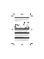
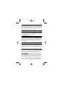
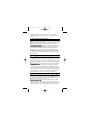
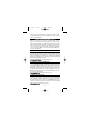
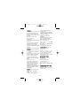
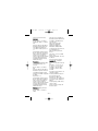
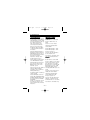
320b.qxd
7/21/00
5:46 PM
Page 1
®
TM
320b.qxd
7/21/00
5:46 PM
Page 2
WARRANTY
The 320B, HD110, HD110T Digital Multimeters are warranted against any defects of
material or workmanship within a period of one (1) year following the date of purchase
of the multimeter by the original purchaser or original user.
Any multimeter claimed to be defective during the warranty period should be returned
with proof of purchase to an authorized Wavetek Meterman Service Center or to the local
Wavetek Meterman dealer or distributor where your multimeter was purchased. See
maintenance section for details.
Any implied warranties arising out of the sale of a Wavetek Meterman multimeter,
including but not limited to implied warranties of merchantability and fitness for a particular purpose, are limited in duration to the above stated one (1) year period. Wavetek
Meterman shall not be liable for loss of use of the multimeter or other incidental or consequential damages, expenses, or economical loss or for any claim or claims for such
damage, expenses or economical loss.
Some states do not allow limitations on how long implied warranties last or the exclusion or limitation of incidental or consequential damages, so the above limitations or
exclusions may not apply to you.
This warranty gives you specific legal rights, and you may also have other rights which
vary from state to state.
D • GEWÄHRLEISTUNG
Die Digitale Multimeter Modelle 320B, HD110, HD110T sind ab Kaufdatum für ein (1)
Jahr gegen Material- und Herstellungsfehler gewährleistet. Siehe Kapitel "Unterhalt und
Reparatur" für Einzelheiten.
Implizierte Schadeforderungen sind auch auf ein Jahr beschränkt. Wavetek Meterman ist
nicht ansprechbar für Gebrauchsverluß oder Folgeschäden, Ausgaben, Gewinnverluß,
usw.
E • GARANTIA
Los Multímetros Digitales Modelos 320B, HD110, HD110T están garantizados contra
cualquier defecto de material o de mano de obra durante un periodo de un (1) año contado a partir de la fecha de adquisición. En la sección de "Mantenimiento y Reparación"
se explican los detalles relativos a reparaciones en garantía.
Cualquier otra garantía implícita está también limitada al periodo citado de un (1) año.
Wavetek Meterman no se hará responsable de pérdidas de uso del multí metro, ni de
ningún otro daño accidental o consecuencial, gastos o pérdidas económicas, en ninguna reclamación a que pudiera haber lugar por dichos daños, gastos o pérdidas
económicas.
F • GARANTIE
Les multimètres digitaux, Modèles 320B, HD110, HD110T sont garantis pour un (1) an
à partir de la date d'achat contre les défauts de matériaux et de fabrication. Voir chapitre
"Maintenance et Réparation" pour plus de détails.
Toute garantie impliquée est également limitée à un an. Wavetek Meterman ne peut être
tenu responsable pour perte d'utilisation ou autres préjudices indirects, frais, perte de
bénéfice, etc.
320b.qxd
7/21/00
5:46 PM
Page 3
CONTENTS
Safety Information..............................................................................................2
Instrument Familiarization and Preparation for Use .......................................... 4
Measurement Procedures ................................................................................ 8
Specifications ................................................................................................ 20
Troublehooting and Repair ............................................................................. 28
D • Inhalt
Sicherheitsinformationen ................................................................................. 2
Vorstellung des Gerätes and Vorbereitung zur Anwendung .............................. 4
Meßprozeduren ................................................................................................ 8
Spezifikationen ............................................................................................... 22
Unterhalt and Reparaturr ................................................................................ 28
E • Contenidos
Información de Seguridad ................................................................................ 3
Familiarización con el instrumento y Preparación para su Uso ........................ 4
Procedimientos de medida .............................................................................. 8
Especificaciones ............................................................................................ 24
Mantenimiento y Reparación ......................................................................... 28
F • Contenu
Informations de Sécurité .................................................................................. 3
Présentation de l’Appareil et Preparations pour l'Emploi .................................. 4
Procédures de Mesure ..................................................................................... 8
Spécifications ................................................................................................ 26
Dépannage et Réparation ............................................................................... 28
– 1 –
320b.qxd
7/21/00
5:46 PM
Page 4
WARNINGS AND PRECAUTIONS
NOTE: The symbol W on the front panel of the multimeter is an international symbol meaning "REFER TO OPERATING INTRUCTIONS. " Warnings and precautions to
avoid personal injury and multimeter damage are listed in this section and in section
"Operating Instructions ".
■ All inputs are protected against continuous overload conditions up to the limits
'of each function's stated input protection (see Specifications). It is very important
that you make yourself familiar with these specifications. Never exceed these limits !
(1500VDC,1000VAC for DC and AC Volts and 60OVDC or AC for all other functions
and ranges.) All voltage and resistance ranges are protected against voltage transients up to 6kV, 10µs duration. Current inputs are fuse-protected. ■Never attempt
to measure voltages or currents that may exceed the ratings marked on the
Function/Range Switch or terminal overlays, or the max. voltage rating above earth
ground. ■Always use extreme caution when working near high voltage sources,
especially when using the two highest VAC or VDC ranges. High voltages can be
lethal and high voltage transients may occur at any time. ■Operator injury or damage to the multimeter may occur during current measurements if the fuse blows in a
circuit which exhibits an open circuit voltage greater than 600 volts. ■Always
inspect test leads, connectors, and probes for cracks or breaks in the insulation
before each use. If any defects are found, replace item immediately. ■Never touch
test leads, tips, or the circuit being tested while power is applied to the circuit being
measured. Isolate yourself! ■When measuring current, check that the multimeter is
connected in series with the load in which the current is to be measured. NEVER connect the multimeter ACROSS a voltage source. ■Please do not use this or any piece
of test equipment without proper training. ■CRT SERVICE SAFETY REMINDER : A
potential danger exists when measuring voltages in the horizontal output and damper
stages of CRT equipment. (High voltage transients greater than 6,000 V). Please refer
to your CRT service manual for proper servicing instructions.
D • Warnungen und Vorsichtsmaßnahmen
Anmerkung: Das Symbol W auf der Frontplatte des Multimeters bedeutet
"GEBRAUCHSANLElTUNG LESEN".
■Überschreiten Sie nie die kontinuierlichen Überlastgrenzen (1500VDC, 1000VAC
für Gleich- und Wechselspannung und 600VDC or AC für alle andere Funktionen
und Bereiche) oder andere Grenzen welche auf dem Gerät markiert sind. ■Außerste
Vorsicht beim Messen von hohen Spannungen (<30V) wenn bei Strommessung die
Sicherung in einem Schaltkreis mit Leerlaufspannung >600V durchbrennt beim
– 2 –
320b.qxd
7/21/00
5:46 PM
Page 5
Messen an Bildröhrgeräten (hohe Spannungsspitzen) ■Unsersuchen Sie Gerät,
Meßkabel, Verbinder, usw vor jeder Messung. Beschädigte Teile nicht verwenden o
■Meßspitzen and Stromkreis während der Messung nicht berühren Sich selbst
isolieren! ■Bei Strommessung, Multimeter immer in Serie mit Schaltkreis verbinden
-- Nie in parallel mit Schaltkreis.
E • Advertencias y Precauciones
NOTA: El símbolo W sobre el panel frontal del multímetro significa "CONSULTE EL
MANUAL DE INSTRUCCIONES".
■No supere nunca los límites de sobrecarga continua (1500 VCC, 1000 VCA en
VDC y VAC, y 600 VCC ■CA en las demás funciones y escalas), a otros límites marcados en el instrumento. ■Existe un serio peligro al medir altas tensiones (<30 V):
■cuando se mide corriente, si salta el fusible en un circuito con tensión de circuito
abierto >600 V ■cuando se trabaja con TRCs (transitorios de alta tensión)
■Inspeccione las puntas de prueba, los conectores y las sondas antes de cada uso.
Si encuentra cualquier defecto, no use el instrumento ■No toque nunca las puntas
de prueba ni el circuito activo sobre el que está midiendo ■¡Aíslese Ud mismo! ■
AI medir corriente, conecte siempre el multímetro en serie con la carga - NUNCA en
paralelo con una fuente de tensión.
F • Avertissements et Précautions
NOTE: Le symbole W sur la face avant de l'appareil veut dire "REFEREZVOUS AU
MANUEL D'UTILISATION. "
■N'excédez jamais les limites de surcharge continue (1500Vcc, 1000Vca pour tension CC et CA et 600Vcc ou Vca pour autres fonctions et calibres) ou dáutres limites marquées sur l'appareil. ■Soyez très prudent quand vous mesurez des tensions
élevées (<30V) pendant des mesures de courant quand le fusible saute dans un circuit avec tension en circuit ouvert de >600 volts En mesurant dans des appareils à
tube cathodique (transitoires à haute tension) ■Inspectez appareil, câbles, connecteurs avant chaque mesure. N'utilisez pas des pièces endommagées ■Ne
touchez pas les pointes de touche ou le circuit pendant les mesures Isolezvous !
■Pour la mesure de courant, connectez l'appareil en série avec le circuit JAMAIS en
parallèle avec une source de tension.
– 3 –
320b.qxd
7/21/00
5:46 PM
Page 6
OVERLOAD INDICATION
Whenever an input signal is larger than the
range selected, an overload symbol "1" will
appear in the display. This indication is normal in the OHMS range when the leads are not
connected to anything or when the measured
value is higher than the selected resistance range. In all other situations, take
immediate steps to remove the cause of the overload condition.
D• Überlastanzeige
Wenn ein Signal die Bereichsgrenze überschreitet erscheint das Symbol "1" in
der Anzeige. Diese Anzeige ist normal bei Widerstandsmessung wenn
Mekabel/spitzen frei stehen oder wenn der Meßwert den Bereich überschreitet. In
alien anderen Fällen ist die Ursache der Überlast sofort zu entfernen.
E • Indicación de sobrecarga
Siempre que una señal de entrada sea mayor que la escala seleccionada,
aparece el símbolo "1" en el visualizador. Dicha indicación es la normal en la
función OHMS cuando las puntas de prueba no están conectadas a ningún sitio,
o cuando el valor medido es superior a la escala de resistencia seleccionada. En
cualquier otra situación, cancele inmediatamente la causa de la sobrecarga.
F • Indication de Surcharge
Quand un signal dépasse la limite d'un calibre choisi, le sybole "1" apparait sur
l'afficheur Ceci est normal dans les calibres de résistance, quand les pointes de
touche ne sont pas connectées, ou si la résistance mesurée dépasse le calibre.
Dans tous les autres cas la cause du dépassement est à enlever immédiatement.
– 4 –
320b.qxd
7/21/00
5:46 PM
Page 7
PREPARATION FOR USE - UNPACKING
Your shipping carton should include the multimeter, one TL-245 Probe Set (one
black, one red), one 9V battery (installed), three fuses (two installed and one
spare inside the case), plus one TP-255 thermocouple (HD110T only). If any of
the items are damaged or missing, immediately return the complete package to
the place of purchase for an exchange.
Tilt stand positions:
D • Gebrauchsvorbereitung - Auspacken
Die Verpackung sollte enthalten: ein Multimeter, ein Meßkabelsatz TL-245 (ein
schwatz, ein rot), eine 9V Batterie (im Gerät), drei Sicherungen (zwei installiert;
eine Reserve im Gerät), plus ein Thermoelement TP-255 (nur HD 110T). Wenn
ein Teil fehlt oder beschädigt ist, gesamte Verpackung zur Verkaufstelle für einen
Austausch zurückbringen, Kippständer wie oben angezeigt einstellen.
E • Preparación del multímetro para su uso - Desembalaje
El embalaje debe contener: el multímetro, un juego de puntas TL- 245 (una
negra y una roja), una pila de 9 V (instalada), tres fusibles (dos instalados y uno
de repuesto dentro de la carcasa), y (solamente en el HD T110T) un termopar
TP-255. En caso de que falte algún componente o se observen daños, devuelva
inmediatamente el paquete completo al lugar donde to adquirió para que se lo
cambien. En la figura se muestran las posiciones inclinadas de apoyo.
E • Préparation pour l’Emploi - Déballage
Votre emballage doit contenir: un multimètre, un jeu de câbles de mesure TL245 (un rouge, un noir), une pile 9V (installée), trois fusibles (deux installés; un
en réserve dans l'appareil), plus un thermocouple TP-255 (HD 110T uniquement). Si une pièce manque ou est endommagée, ramenez l'ensemble au point
de vente pour un échange. Positionnez la béquille comme illustré ci-dessus.
– 5 –
320b.qxd
7/21/00
5:46 PM
– 6 –
Page 8
320b.qxd
7/21/00
5:46 PM
Page 9
INITIAL CHECKOUT
Connect red test lead to the V-W Input Connector and black test lead to the COM
Input Connector. Turn the Function/Range Switch to the 20MW position. With the
two test lead tips separated, the Digital Display should read 1 (overload). Turn
Function/Range Switch to each W position. With test lead tips in contact, the display should read 0 in each position. (00.1 or 00.2 in 200W position due to test
lead resistance). The decimal point should be positioned as follows:
20MW
2MW
200kW
0.00
.000
00.0
20kW
2kW
200W
0.00
.000
00.0
D • Funktionstest
Rotes Meßkabel mit V-W Eingang verbinden and schwarzes mit COM Eingang.
Funktionsschalter auf 20MW stellen. Mit, freistehenden Prüfspitzen wird Überlast
"1" angezeigt. Wählen Sie jede W Position an. Mit kurzgeschlossenen Meßspitzen
wind in jeder Position Null angezeigt (00.1 oder 00.2 in 200W Position wegen
Meßkabelwiderstand). Dezimalpunkt Position wie in obiger Tabelle.
E • Comprobación inicial
Conecte la punta de prueba roja al conector de entrada V-W, y la negra al conector de entrada COM. Gire el selector de Función/Escala/Off hasta la posición
20MW. Con los extremos de las pumas separados, el visualizador debe indicar
"1" (sobrecarga). Vaya girando el selector por todas las posiciones de W. Con los
extremos de las puntas de prueba en contacto, el visualizador debe indicar 0 en
cada posición (00.1 0 00.2 en la posición 200W, debido a la resistencia de los
cables). La posición del punto decimal debe ser como se muestra en la tabla anterior.
F • Test de Fonctionnement
Connectez le cordon rouge à l'entrée V-W et le noir à l'entrée COM. Placez le
sélecteur de fonctions sur 20MW. Avec les pointes de touche séparées, l'afficheur
montre "1" (dépassement de calibre). Choisissez chaque position W. Avec les
pointes court-circuitées, l'affichage indique 0 dans chaque position (00.1 ou 00.2
en position 200W pour résistance des câbles). Positionnement du point décimal
comme indiqué dans le tableau ci-dessus.
– 7 –
320b.qxd
7/21/00
5:46 PM
Page 10
MEASURING PROCEDURES
General Procedures: ❶ When connecting or disconnecting test leads to
a circuit, always first turn off power to device or circuit being tested and
discharge all capacitors. ❷ If magnitude of signal is not known, set
switch to highest range and reduce until satisfactory reading is
obtained. ❸ Strictly observe the max input limits.
D • Meßprozeduren
Allgemein: ❶ Vor Verbinden und Trennen der Meßkabel mit dem Schaltkreis,
diesen abschalten und Kondensatoren entladen, ❷ Bei unbekannter Signalgröße,
bei höchstem Bereich beginnen and dann niedriger schalten bis gate Auflösung
erreicht wird. ❸ Maximale Grenzen nicht überschreiten.
E • Procedimientos de medida
En general:. ❶ Cuando vaya a aplicar o retirar las pumas de prueba a/de un circuito, en primer lugar desconecte siempre la alimentación del dispositivo o circuito sometido a prueba y descargue todos los condensadores. ❷ si no conoce
la magnitud de la señal, ponga el selector en la escala más alta y vaya reduciendo hasta obtener una lectura satisfactoria, ❸ Observe estrictamente los límites
máximos de entrada .
F • Procédures de Mesure
Général: ❶ Avant de connecter ou de déconnecter les cordons de test, coupez I
lálimentation du circuit mesuré et déchargez les condensateurs. ❷ Si la magnitude du signal n’est pas connue, commencez avec le calibre le plus élevé, et
diminuez ensuite jusqu'à obtenir une bonne lecture. ❸ Ne dépassez pas les limites d'entrée.
DC AND VOLTAGE MEASUREMENT (See Fig 1)
❶ Connect red test lead to V-W Input and black test lead to COM Input. ❷ Set
Function/Range Switch to desired DCV or ACV position. ❸ Touch Probe tips
across voltage source (in parallel with circuit). ❹ Voltage value will appear on
Digital Display along with the voltage polarity (negative DC measurements).
Note for AC Measurements: The AC converter used in the HD110, HD110T and
320 models is "average-responding." An RMS value is determined by first rectifying and filtering the signal to obtain the average value. The average value is
then scaled upward by a factor of 1.11 to obtain the RMS value. Different scaling
factors need to be applied for other waveforms (1 for square waves; 1.733 for
triangle; 3.247 for full wave rectified sine wave; 2.591 for half wave rectified sine
wave). Please note that these correction factors only apply for standard waveforms that are free from noise and distortion. True RMS values of nonsinusoidal
– 8 –
320b.qxd
7/21/00
5:47 PM
– 9 –
Page 11
320b.qxd
7/21/00
5:47 PM
Page 12
and distorted signals can be measured directly and more accurately with
Wavetek Models RMS225 or HD160 which feature a "True-RMS responding"
converter.
D • Gleich und Wechselspannungsmessung
❶ Rotes Meßkabel mit V-W Eingang verbinden and schwarzes mit COM.
❷ Funktionsschalter auf gewünschten Bereich in DCV oder ACV stellen.
❸ Meßspitzen mit Meßkreis verbinden - in parallel zur Spannungsquelle.
❹ Meßwert ablesen (automatische Polaritätsanzeige bei DC Messungen).
Anmerkung für AC Messungen: AC Messungen sind Mittelwertmessungen. Das
Signal wird gleichgerichtet um den Mittelwert zu erhalten, and wird dann mit
1.11 multipliziert um den Effektivwert einer Sinuswelle zu erhalten. Andere
Multiplikatoren müssen für andere Wellenformen angewendet werden, Echte
Effektivwerte von nicht-sinusförmigen oder verzerrten Signalen können genauer
and direkt mit den Wavetek Echt-Effektivwertmultimetern RMS225 and HD 160
gemessen werden.
E • Medidas de tensión CC y CA (DCV y ACV)
❶ Conecte la punta de prueba roja al conector de entrada V-W, y la negra a la
entrada COM. ❷ Ponga el selector de Función/Escala en la posición DCV o ACV
deseada.❸ Con los extremos de las puntas de prueba, toque los puntos entre los
cuales desee medir la tensión (en paralelo con el circuito). ❹ Aparece el valor de
la tensión en el visualizador LCD, junto con la polaridad sí es una medida de CC
(DCV).
Nota para medidas de CA: Las medidas de CA son de "respuesta promediada",
rectificándose y filtrándose la señal para obtener el valor medio. Este valor se
aumenta en un factor de 1.11 para obtener el valor eficaz (RMS) de una onda
sinusodal pura. Para otras formas de onda es necesario aplicar otros factores de
escala, Los valores eficaces de señales no sinusoídales o distorsionadas pueden
medirse directamente, con mayor precisión, utilizando los Modelos RMS225 0
HD 160 de Wavetek, que proporcionan el 'Verdadero valor eficaz" (TRMS).
F • Measure de Tension CC et CA
❶ Connectez le cordon rouge à l'entrée V-W et le noir à /entrée COM. ❷ Placez
le sélecteur sur le calibre souhaité en DCV (cc) ou ACV (ca). ❸ Connectez les cordons au circuit - en parallèle avec la source de tension. ❹ Lisez la mesure sur
l'afficheur (avec la polarité pour les mesures en CC).
Note pour les mesures en CA: Les mesures en CA sont de mesures de valeur
moyenne. Le signal est rectifié et filtré pour obtenir la valeur moyenne, et cette
valeur est multipliée par 1.11 pour obtenir la valeur efficace correspondent à une
sinusoïdale pure. D'autres facteurs de multiplication doivent être appliqués pour
– 10 –
320b.qxd
7/21/00
5:47 PM
Page 13
d'autres formes d'onde. La valeur efficace de signaux non-sinusoïdaux ou déformés est obtenue directement et avec une plus grande précison avec les modèles
RMS225 ou HD160 de Wavetek.
DC AND AC CURRENT MEASUREMENT (seeFig. 2)
❶ Connect red test lead to the A Input for current measurements up to two
amperes or to the 10A input for current measurements to ten amperes. Connect
black test lead to COM input Connector. ❷ Set Function/Range Switch to desired
DCA or ACA position. When the 10A Input Connector is used, the Function/Range
Switch should be placed in the 20m/10A position. ❸ Open circuit in which current is to be measured. Securely connect test leads in series with the load in which
current is to be measured. ❹ Turn on power to circuit being tested. ❺ Read current value on Digital Display.
D • Gleich und Wechseelstrommessung
❶ Rotes Meßkabel für Messungen bis 2A mit dem A Eingang verbinden, oder für
Messungen bis 10A mit dem 10 Eingang. Schwarzes Meßkabel mit COM
verbinden. ❷ Funktionsschalter auf gewünschten Bereich in DCA oder ACA
stellen. Bei Verwendung des l0A Einganges, nur 20m/10A Bereich wählen. ❸
Meßkreis öffnen. Meßspitzen sicher in Serie mit dem Stromkreis verbinden. ❹
Meßkreis einschalten. ❺ Stromwert ablesen.
Anmerkúng für AC Meßungen: Siehe Spannungsmessung.
E • Medida de Corriente CCy CA (DCA y ACA)
❶ Conecte la punta de prueba roja a la entrada A para medidas de corriente hasty
2 A, o a la entrada 10A pare medidas hasta 10A. Conecte la punta de prueba negra
a la entrada COM. ❷ Ponga el selector de Función/Escala en la posición DCA o
ACA deseada. Si utiliza la entrada de 10A, ponga el selector en la posición
20m/10A. ❸ Abra el circuito por el que circula la corriente que desea medir.
Conecte las puntas de prueba en serie con la carga, asegurando bien la conexión.
❹ Conecte la alimentación del circuito sometido a prueba. ❺ Aparece el valor de
la corriente en el visualizador LCD.
Note pare medidas de CA: Vea Medidas de tensión CC y CA.
F • Mesure de Courant CC et CA
❶ Connectez le cordon rouge à l'entrée A pour mesures jusqu'à 2A et à l'entrée
10A pour mesures jusqu'à 10A. Connectez le cordon noir à l'entrée COM. ❷
Placez le sélecteur sur le calibre souhaité en DCA (cc) ou ACA (ca). Quand l'entrée 10A est utilisée, placez le sélecteur sur 20m/10A. ❸ Ouvrez le circuit à
mesurer et connectez les pointes de touche solidement en série avec le circuit. ❹
Mettez le circuit sous tension. ❺ Lisez la mesure.
Note pour mesures en CA: Voir rnesures de tension.
– 11 –
320b.qxd
7/21/00
5:47 PM
Page 14
RESISTANCE MEASUREMENT (See Fig. 3)
All resistance ranges on the multimeter are low-power ohms which allow accurate
measurements of in-circuit resistance. ❶ Connect red test lead to V W Input and
black test lead to COM Input. ❷ Set Function/Range Switch to desired W position. ❸ Connect test leads to circuit being measured. ❹ Read resistance value on
Digital Display.
D • Widerstandsmessung
Alle Widerstandsbereiche verwenden eine niedrige Spannung and erlauben eine
Messung im Schaltkreis. ❶ Rotes Meßkabel mit V W Eingang and schwarzes mit
COM verbinden. ❷ Funktionsschalter auf gewünschte W Position stellen. ❸
Meßspitzen mit Schaltkreis verbinden. ❹ Meßwert ablesen.
– 12 –
320b.qxd
7/21/00
5:47 PM
– 13 –
Page 15
320b.qxd
7/21/00
5:47 PM
Page 16
E • Medidas de Resistencia
Todas las escalas de resistencia del multímetro utilizan una excitación de baja
potencia, permitiendo una medida precisa de la resistencia dentro de circuito. ❶
Conecte la punta de prueba roja a la entrada V W, y la negra a la entrada COM. ❷
Ponga el selector de función/escala en la posición W deseada. ❸ Aplique las
puntas de prueba al circuito que desee medir ❹ Aparece el valor de la resistencia en el visualizador LCD.
F • Mesure de Résistance
Tous les calibres de résistance utilisent une basse tension et permettent la mesure
en circuit. ❶ Connectez le cordon rouge à l'entrée VW et le noir à lentrée COM.
❷ Placez le sélecteur sur la position W souhaitée. ❸ Connectez les cordons au cir-
cuit à mesurer. ❹ Lisez la valeur affichée.
DIODE AND TRANSISTOR TEST (See Fig 4)
The diode test function allows accurate measurements of forward voltage drops
across diodes and transistor junctions. A constant-current source forces 1mA of
current into the semiconductor junction under test, which results in the voltage
drop being displayed on the Digital Display. This function also permits measurement of in-circuit semiconductor junctions with as little as 500W in parallel with
the transistor or diode. The limited current produced by the instrument in the
Diode Test Function minimizes the possibility of damage to lowpower semiconductor junctions.
❶ Connect the red test lead to the V W Input and the black test lead to the COM
Input. ❷ Set Function/Range Switch to the Diode Test (G) position. ❸
Connect test leads to device. ❹ Read forward voltage drop on Digital Display.
If the Digital Display reads "1" (overload), reverse the lead connections. The
placement of the leads when the forward voltage is displayed (normally 600mV to
900mV) indicates the orientation of the diode. The red lead is then connected to
the anode and the black lead to the cathode. If "1" is displayed with both lead connections, the junction is open. If a low reading (less than 1V) is obtained with
both lead connections, the junction is shorted internally or (if the junction is measured in a circuit) is shunted by a resistance less than 500 ohms. In the latter case
the junction must be disconnected from the circuit in order to verify its operation.
Transistors can be tested in the same manner as diodes by checking the two diode
junctions formed between the base and emitter and the base and collector of the
transistor.
Note: When diode test voltage drop is <0.4V, an W symbol appears in the display,
and beeper sounds (see continuity test).
– 14 –
320b.qxd
7/21/00
5:47 PM
Page 17
D • Dioden - und Transistortest
❶ Rotes Meßkabel mit VW and schwarzes mit COM verbinden. ❷
Funktionsschalter auf G stellen. ❸ Meßkabel mit Diode verbinden. ❹
Spannungsabfall in Durchlaßrichtung ablesen. Rotes Meßkabel ist mit
Anode and schwarzes mit Kathode verbunden. Bei Überlastanzeige "1",
Verbindung umdrehen. Bei Überiastanzeige in beiden Fällen ist die Diode
offen. Bei sehr niedriger Spannung in beiden Richtungen (<1 V) ist die Diode
kurzgeschlossen.
Anmerkung: Bei Spannungsabfall <0.4V, W-Symbol in der Anzeige and
Dauerton (siehe Durchgangsprüfung).
– 15 –
320b.qxd
7/21/00
5:47 PM
Page 18
E • Comprobación de diodes y transistores
❶ Conecte la punta de prueba roja a la entrada VW, y la negra a la entrada
COM. ❷ Ponga el selector de función/escala en la posición de
Comprobación de Diodos G. ❸ Aplique las puntas de prueba al dispositivo. ❹ Aparece la caída de tensión directa en el visualizador LCD. La punta
roja se conecta al ánodo, y la negra al cátodo. Si el visualizador indica "1"
(sobrecarga), invierta la conexión de las puntas de prueba. Si aparece "1" en
ambos sentidos, la unión está abierta. Si obtiene una indicación baja (<1 V)
en ambos sentidos, la unión está cortocircuitada internamente.
Nota: Cuando tensión <0.4V aparecerá un símbolo W en la esquina superior izquierda del visualizador, generándose un tono acústico constante.
F • Test de Diodes et de Transistors
❶ Connectez le cordon rouge à l'entrée VW et le cordon noir à l'entrée CAM.
❷ Placez le sélecteur sur G ❸ Connectez les pointes de touche à la
diode. ❹ Lisez la chute de tension en direction passante. Le cordon rouge
est connecté à l'anode et le cordon noir à la cathode. Si "1" (surcharge) est
affiché avec les deux branchements, la diode est ouverte. Si une faible tension (<1 V) est affichée dans les deux cas, la diode est court-circuitée.
Note: Pour une chute de tension de <0.4V, le symbole W apparait sur l'afficheur, accompagné d'un signal sonore. (voir test de continuité).
CONTINUITY TEST
❶ Place Function/Range Switch to the 200W position. ❷ Connect red test
lead to the VW input and the black test lead to the COM input. With the test
leads separated or measuring an out-of-range resistance, the Digital Display
will indicate "1" (Overload). ❸ Place one test lead probe at one end of cable
or circuit to be tested. Use the other test lead to trace the circuit or cable until
the circuit is complete. When continuity is established (resistance <80W), an
W symbol will appear in the upper left-hand corner of the Digital Display and
a constant tone will be generated.
D • Durchgangstest
❶ Funktionsschalter auf 200W-Bereích stellen. ❷ Rotes Meßkabel mit VW
Eingang and schwarzes mit COM Eingang verbinden. Mit frei-stehenden
Meßspitzen, oiler bei Bereichsüberschreitung wird "1" angezeigt. ❸ Eine
Meßspize mit einem Kabelende verbinden. Mit anderer Meßspize Meßkreis
oiler andere Kabelenden absuchen bis Durchgang gefunden ist (<80W).
Dabei wird ein W Symbol angezeigt and ein kontinuierlicher Ton abgegeben.
– 16 –
320b.qxd
7/21/00
5:47 PM
Page 19
E • Prueba de continuidad
❶ Ponga el selector de función/escala en 200W. ❷ Conecte la punta de
prueba roja a la entrada VW, y la negra a la entrada COM. Con las puntas
separadas, o si la resistencia está fuera de escala, la indicación en el visualizador será "1" (sobrecarga). ❸ Ponga una punta en un extremo del cable
o circuito que desee medir. Siga el circuito o cable con la otra punta hasta
completar el circuito. Cuando se establezca la continuidad (<80W), aparecerá un símbolo W en la esquina superior izquierda del visualizador, generándose un tono acústico constante.
F • Test de Continuité
❶ Placez le sélecteur sur le calibre 200W. ❷ Connectez le cordon rouge à
l'entrée VW et le cordon noir à l'entrée COM. Avec les pointes de touche
séparées au en dépassement de calibre, l'afficheur indique "1". ❸ Attachez
une pointe de touche à une extrémité de câble ou de circuit. Avec l'autre
pointe, touchez les autres extrémités de câbles ou explorez le circuit jusqu'à
ce que une continuité soft établie (<80W). A ce moment le symbole W est
affiché dons le coin supérieur gauche de l'afficheur, accompagné d'un ton
continu.
– 17 –
320b.qxd
7/21/00
5:47 PM
Page 20
TEMPERATURE MEASUREMENT ( HD110T ONLYSee Fig 5)
The HD110T is designed for use with an industry-standard type K thermocouple
having a miniature or subminiature input connector.
❶ Disconnect the test leads from the multimeter. ❷ Insert type K thermocouple
into the input connector at the top of the multimeter, above the LCD. ❸ Place the
Function/Range Switch in the °F position. ❹ Place the thermocouple probe in the
area to be measured and read the meter in °F.
Note: Remove thermocouple plug from the meter for normal voltage, current,
and resistance readings.
D • Temperaturmessung (HD110T)
Mit dem HD110T können standard Type-K Thermoelemente mit Mini oder SubMini Verbinder verwendet werden.
❶ Meßkabel vom Multimeter entfernen. ❷ Type-K Thermofühler mit Eingang am
Kopf des Gerätes verbinden. ❸ Funktionsschalter auf °F stellen. ❹ Meßfühler in
gewünschte Umgebung bringen and Meßwert in °F ablesen.
Anmerkung: Thermofühler far Spannungs-, Strom- und Widerstandsmessungen
entfernen.
E • Medidas de temperatura (HD110T Solamente)
El HD110T admite un termopar estándar de tipo K, con un conector de entrada
miniatura o sub-miniatura.
❶ Desconecte las puntas de prueba del multímetro. ❷ Inserte el termopar de tipo
K en el conector de entrada, situado encima del visualizador LCD. ❸ Ponga el
selector de función/escala en la posición °F. ❹ Sitúe la sonda del termopar en el
área cuya temperatura desee medir, y observe la lectura en el visualizador, en °F
Mota: Retire el termopar del multímetro cuando vaya a hacer medidas de tensión,
corriente y resistencia.
F • Mesure de Temperature (HD110T uniquement)
Le HD 110T est conçu pour utilisation avec thermocouples de type K avec connecteur miniature ou sub-miniature.
– 18 –
320b.qxd
7/21/00
5:47 PM
Page 21
❶ Déconnectez les cordons de test du multimètre. ❷ Connectez le thermocouple
de type K à la borne d'entrée se trouvant au-dessus de l'appareil. ❸ Placez le
sélecteur sur la position °F. ❹ Placez le thermocouple dans l'endroit à mesurer et
lisez la température en °F sur l'afficheur.
Note: Enlevez le thermocouple pour les mesures normales de tension, courant et
résistance.
– 19 –
320b.qxd
7/21/00
5:47 PM
Page 22
SPECIFICATIONS
General Specifications
Accuracies are stated as ±(% reading
+ number of digits), guaranteed for
one year, 25°C ± 5°C. Specifications
are subject to change without notice.
Operating Temperature: 0°C to +50°C
Storage Temperature: -40°C to +65°C
with battery removed (above 50°C).
Display: 3-1/2 digit LCD with a maximum reading of 1999; 7/8" (21 mm)
tall.
Polarity Indication: Automatic (- indicated)
Power: Single, standard 9-volt transistor battery, NEDA 1604
Battery Life (continuous, nominal):
Alkaline: 1,500 hrs; Zinc-Carbon:
1,200 hrs.
Low Battery Indicator: indicates when
100 hours of battery life remain.
Shock and Vibration: Meets
MILT28800 Class II Type A
Specifications.
Relative Humidity: 0% to 80%, 0°C to
35°C; 0% to 70%, 35°C to 50°C.
Temperature Coefficient: <0.1 x specified accuracy per °C from 0°C to
20°C and 30° to 50°C
Max. Common Mode Voltage:
150OVDC or peak AC.
Dimensions (HxWxD): 320B:
6.85"x3.65"x1.8" (17.4x9.3x4.6cm)
HD110 & HD110T: 7"x 3.9"x2.0"
(7.8x9.9x5.1 cm) Weight: 320B:14.5
ounces (412 gm) HD110 & HD110T:
19 ounces (535 gm
Measurement Rate: 2.5 measurements
per second nominal.
Case: Model 320B: High-impact, ABS,
fire-retardant plastic
Model HD110, HD110T: Reinforced
high impact fire-retardant plastic.
Included with instrument: One ninevolt battery; one spare 2A fuse; one
TL245 Probe Set; one operator's manual
Electrical Specifications
DC Volts
Ranges: 200mV, 2, 20, 200,1500V
Resolution: 100uV in 200mV range
Accuracy: 0.1 % rdg ±1 dgt Input
Impedance (all ranges) :10 MW
NMR: > 60dB above 49Hz.
CMR: > 60dB above 49Hz.
Response Time: <2 sec
Overvoltage Protection: 1500VDC or
peak AC, any range
Transient Protection: 6kV for 10ms
AC Volts ( Sine Wave only)
Ranges: 200mV, 2, 20, 200, 1000V
Resolution: 100mV on 200mV Rng
Accuracy:
200mV, 2, 20V ranges: 45Hz - 2kHz:
±(0.75% rdg+ 3dgt) 2kHz - 5kHz:
±(1.5% rdg+ 5dgt)
200V: 45Hz -1 kHz: ±(0.75% rdg+
3dgt);
1000V: 45Hz - 500Hz: ±(0.75% rdg+
3dgt) 500Hz -1 kHz: ±(1.5% rdg+
5dgt)
Conversion Technique: Average sense,
RMS indicating
Input Impedance (All ranges): 10MW
shunted by less than 75pF
Response Time: <2 sec
Overvoltage Protection: 1000Vrms AC
(1500V peak) or 250VDC (5 Sec max.
above 450Vrms on 200mV range.)
Transient Protection: 3kV for 10ms
– 20 –
320b.qxd
7/21/00
5:47 PM
DC Current
Ranges: 200mA, 2, 20, 200mA, 2, 10A
Resolution: 100nA in 200mA range
(HD110T uses 2A DC range for °F)
Accuracy: 200mA to 2A ranges: 0.35%
rdg ±1 dgt
1OA range: 1.5% rdg ± 1 dgt
Response Time: <2 sec
Voltage Burden:
200mA to 200mA ranges: 250mV max.
at full-scale
2A range: 700mV max. at full-scale
10A range: 1V max. at full-scale
Overcurrent Protection: A Input:
2A/600V fuse, 3000A interrupt rating;
10A Input:
15A/600V fuse; 100kA interrupt rating
AC Current
Conversion Technique: Average sensing, calibrated to display RMS value
of sine wave.
Ranges: 200mA, 2, 20, 200mA, 2, 10A
Resolution: 100nA in 200mA range
Accuracy - 200mA to 2A ranges:
0.9%rdg ± 3 dgt (45Hz to 2kHz)
10A range: 1.5%rdg ± 3 dgt (45Hz to
400Hz)
Response Time: <2 sec.
Voltage Burden: 200mA to 200mA
ranges: 250mV max. at full-scale
2A range: 700mV max. at full-scale
10A range: 1V max. at full-scale
Overcurrent Protection: A Input:
2A/600V fuse, 3000A interrupt rating;
10A Input: 15A/600V fuse; 100kA
interrupt rating
Resistance (Low-power ohms on al!
ranges)
Ranges: 200W, 2, 20, 200kW, 2,
20MW
Resolution: 0.1W in 200W range
Page 23
Accuracy: 200W to 2MW ranges
0.2%rdg ± 1 dgt
20MW range: 1.0%rdg ±1 dgt Max.
Test Current (Range/A): 200W/2.5mA;
2kW/250mA; 20kW/25mA;
200kW/2.5mA; 2MW/250nA;
20MW/25nA
Max. Open Circuit Voltage: 0.3V all
ranges except 200W range: 3V
Max. In Range Voltage: 200mV, all
ranges (low power ohms)
Response Time: <2 sec, except 20MW
range, <10sec
Overload Protection: 600VDC or RMS
AC, any range
Transient Protection: 3kV for 10ms
Temperature (°F) - HD110T only
Ranges: -4°F to 1999°F
Resolution: 1°F
Accuracy - °F: -4° to 31 °: ±6°; 32° to
572°: ±5°; 573° to 800°: ±1 %rdg
±2°; 801° to 1000°: ±2%rdg ±3°;
1001° to 1999°: ±3%rdg
Thermocouple Type: Type K; miniature
or subminiature connector
Diode Test (200W range)
Range: 0V to 2V
Resolution: 1mV
Accuracy: 6% rdg ±2 dgt
Test Current: 1mA, ±20%
Response Time: <1 sec
Overload Protection: 60OVDC or RMS
AC
Continuity Indicator (200W range)
Threshold: < 80W;
Indication: W symbol on display and
continuous tone
– 21 –
320b.qxd
7/21/00
5:47 PM
Page 24
D • Spezifikationen
Modell HD110, HD110T: Verstärkter
Aallgemeine Spezifikationen
stoßsicherer, feuerwehrender ABS
Genauigkeiten sind als ±(% vMW
Kunststoff. Lieferumfang: Eine 9V
+Anzahl Digits) angegeben,
gewährleistet für ein Jahr, 25°C ± 5°C. Batteries eine 2A Ersatzsicherung; ein
TL-245 Meßkabelsatz; eine
Spezifikationen können ohne vorherige Gebrauchsanleitung
Ansage geändert werden.
Elektrische Spezifikationen
Betriebstemperatur: 0°C bis +50°C
Gleichspannung
Lagertemperatur: -40°C bis +65°C
Bereiche: 200mV, 2, 20, 200,1500V
Batterie entfernt (über 50°C).
Auflösung: 100mV im 200mV Bereich
Anzeige: 3-1/2 Digit LCD,1999
Genauigkeit: 0.1% vMW ±1 Dgt
Punkte; 21mm hohe Ziffern.
Eingangsimpedanz (á11e Ber.) :10
Polaritätsanzeige: Automatisch (MW
angezeigt)
NMR: > 60dB über 49Hz.
Stromversorgung: Eine standard 9Volt Batterie, NEDA 1604
CMR: > 60dB über 49Hz.
Autonomie (kontinuierlich, nominal):
Ansprechzeit: <2 sec
Alkaline: 1,500 Std; Zink-Kohle: 1,200
Überspannungsschutz: 1500VDC oder
Std.
AC Spitze, alle Bereiche
Entladene Batterieanzeige: bei <100
Transientenschutz: 6kV für 10ms
Stunden Autonomie.
Wechselspannung (Nur Sinuswelle)
Schock und Vibration: MIL-T28800
Klasse II Type A.
Bereiche: 200mV, 2, 20, 200, 1000V
Relative Feuchte: 0% bis 80%, 0°C
Auflösung: 100mV im 200mV Bereich
bis 35°C; 0% bis 70%, 35°C bis
Genauigkeit: 200mV, 2, 20V Bereiche
50°C.
45Hz bis 2kHz: ±(0.75% vMW+ 3Dgt)
Temperaturkoefficient: <0.1 x
2kHz bis 5kHz: ±(1.5% vMW+ 5Dgt)
angegebene Genauigkeit per °C von
200V, 45Hz bis 1kHz: ±(0.75% vMW+
0°C bis 20°C and 30° bis 50°C
3Dgt); 1000V, 45Hz bis 500Hz:
±(0.75% vMW+ 3Dgt); 500Hz bis
Max. Gleichtaktspannung: 1500VDC
1kHz: ±(1.5% vMW+ 5Dgt)
oder AC Spitze.
Umsetzung: Mittelwert messend effekAbmessungen (HxBxT):
tivwert anzeigend (RMS)
320B:17.4x9.3x4.6cm HD110 &
HD110T:17.8x9.9x5.1cm
Eingangsimpedanz (alle Ber,): 10MW
mit <75pF in parallel
Gewicht: 320B: 412gm HD110 &
HD110T: 535gm
Ansprechzeit: <2 Sek
Meßrate: 2.5 Messungen pro Sekunde Überspannungsschutz: 1000VRMS AC
nominal.
(1500V Spitze) oder 250VDC (5 Sek,
Gehäuse : Modell 320B: Stoßsicherer, max. über 450Vrms in 200mV Ber.)
feuerwehrender ABS Kunststoff.
– 22 –
320b.qxd
7/21/00
5:47 PM
Page 25
Transientenschutz: 3kV für 10ms
Auflösung: 0.152 im 200W Bereich
Gleichstrom
Genauigkeit: 200W bis 2MW Bereiche
0.2%vMW ± 1 Dgt 20MW Bereich:
Bereiche: 200mA, 2, 20, 200mA, 2,
1.0%rdg ±1 dgt
10A (HD110T: 200mA, 2, 20, 200mA,
10A)
Max. Test Strom (Bereich/A):
200W/2.5mA; 2kW/250mA,
Auflösung: 100nA im 200mA Bereich
20kW/25mA; 200kW/2.5mA;
Genauigkeit: 200mA bis 2A Bereiche:
2MW/250nA; 20MW/25A Max.
0.35% vMW ±1 Dgt 10A Bereich:
Leerlaufspannung- 0.3V alle Bereiche,
1.5% vMW ± 1 Dgt Ansprechzeit: <2
ausg. 200W Bereich: 3V
sec
Max. Testspannung: 200mV, alle
Spañnungsabfall: 200mA bis 200mA
Bereiche
Bereiche: 250mV max. im Endbereich
2A Ber.: 700mV max. im Endbereich
Ansprechzeit: <2 Sek, ausg. 20MW
10A Ber.: 1V max. im Endbereich
Bereích, <10sec
Überstromschutz: A Eingang: 2A/600V Überlastschutz: 600VDC oder eff. AC,
Sicherung, 3000A Trennvermögen;
alle Bereiche
10A Eingang: 15A/600V Sicherung,
Transientenschutz: 3kV für 10ms
100kÁ Trennvermögen
Temperatur (°F) - nur HD110T
Wechselstrom
Bereiche: -4°F bis 1999°F Auflösung:
Umsetzung: Mittelwertbildend, kalibri- 1°F
ert für Effektivwertanzeige einer
Genauigkeit - °F: -4° bis 31°: ±6°;
Sinuswelle.
32° bis 572°: ±5°; 573° bis 800°:
Bereiche: 200mA, 2, 20, 200mA, 2,
±1%vMW ±2°; 801° bis 1000°:
1OA
±2%vMW ±3°; 1001° bis 1999°:
Auflösung: 100nA im 200mA Bereich
±3%vMW
Genauigkeit - 200mA bis 2A Bereiche: Thermofühler: Type K; Miniatur- oder
0.9%vMW ±3 Dgt (45Hz bis 2kHz)
Subminiatur Verbinder
10A Bereich: 1.5%vMW ± 3 Dgt (45Hz
Diodentest (200W Bereich) Bereich:
bis 400Hz)
0V bis 2V Auflösung: 1mV
Ansprechzeit: <2 sec.
Genauigkeit: 6% vMW ±2 Dgt
Spannungsabfall: 200mA bis 200mA
Teststrom: 1mA, ±20% Ansprechzeit:
Bereiche: 250mV max. bei Endberich
<1 Sek Überlastschutz: 600VDC oder
2A Ber.: 700mV max. bei Endberich
RMS AC
10A Ber: 1V max. bei Endberich
Durchgangsanzeige (200W Bereich)
Überstromschutz: A Eingang: 2A/600V
Schwelle:
< 80W;
Sicherung, 3000A Trennvermögen;
Anzeige: W Symbol in Anzeige and
10A Eingang: 15A/600V Sicherung,
akustisches Signal
100kA Trennvermögen
Widerstand (Niedrige Spannung in
alien Bereichen)
Bereiche: 200W, 2, 20, 200kW, 2,
20MW
– 23 –
320b.qxd
7/21/00
5:47 PM
Page 26
E • Especificaciones
Especificaciones generales
Especificaciones eléctricas
Los valores de precisión se dan como Voltios CC
±(% de la lectura + núm. de dígitos), y
están garantizados por un año, a 25°C Escalas: 200mV; 2, 20, 200,1500V
±5°C. Las especificaciones están suje- Resolución: 100uV en la esc. de
tas a cambios sin previo aviso.
200mV
Temp. de funcionamiento: 0°C a
Precisión: 0.1 % lect. ±1 dígito
+50°C Temp. de almacenamiento: Impedancia de entrada (todas las
40°C a +65°C sin la eila (>50°C)
escalas): 10MW
Visualización: LCD de 3-1/2 dígitos,
Rechazo NMR: >60 dB por > 49 Hz
con indicación máxima de 1999; 21
mm de altura
Rechazo CMR: >60 dB por > 49 Hz
Indicación polaridad: Automática ( - )
Tiempo de respuesta: <2s
Alimentación: Una pila normal de 9 V,
Protección sobrecarga: 1500 VCC o
NEDA 1604 Duración de la eila (continua, nominal): Alcalina: 1.500 horas; pico CA, cualquier escala
Prot. transitorios: 6 kV durance 10 ms
Zinc-carbono: 1.200 horas
Voltios CA (Solamente señal sinuIndicación de "eila baja": cuando
soidal)
quedan unas 100 horas de use
Choque y vibración: Según especifica- Escalas: 200mV, 2, 20, 200, 1000V
ciones MIL-T28800 Clase II Tipo A
Resolución: 100mV en esc. de 200 mV
Humedad relativa: 0% a 80% (0°C a
Precisión escalas: 200mV, 2, 20V 45
35°C); 0% a 70% (35°C a 50°C)
Hz a 2 kHz: ±(0.75% lect+ 3 dgt) 2
Máxima tensión en modo común:
kHz a 5 kHz: ±(1.5% lect+5 dgt) 200V:
1500 VCC o pico CA
45Hz a 1kHz: ±(0.75% lect+ 3 dgt);
Dimensiones (AI x An x Pr): 320B:17.4 1000V: 45Hz a 500Hz: ±(0.75%
lect+3 dgt) 500Hz a 1kHz: ±(1.5% lect
x9.3x4.6cm; HD110 y HD110T:
+5 Dgt)
17.8x9.9x5:1 cm Peso: 320B: 412 g
Técnica de conversión: Repuesta proHD110 y HD110T: 535 g
mediada, valor eficaz indicandó
Velocidad de medida: 2.5 medidas por
Impedancia de entrada (todas las
segundo (nominal)
escalas): 10MW, shunt <75pF
Cercasa: 320B: plástico resistente a
impactos, ABS, inflamabilidad retarda- Tiempo de respuestra: <2s
da; HD110 y HD110T: Plástico reforza- Protección sobrecarga: 1000 Vef CA
do resistente a impactos, inflamabili(1500 Vp), o 250 VCC (5s máx por
dad retardada
encima de 450 Vef en esc. de 200 mV)
Incluido con el instrumento: 1 pila de
Prot. transitorios: 3 kV durante 10 ms
9V; 1 fusible de repuesto de 2A; 1
juego de puntas TL-245; 1 manual de
instrucciones
– 24 –
320b.qxd
7/21/00
5:47 PM
Corriente CC
Escalas: 200mA; 2, 20, 200mA; 2, 10A
(HD110T: 200mA; 2, 20, 200mA; 10A)
Resolución: 100nA en esc. de 200mA
Precisión: 200uA a 2A: 0.35% lect. ±1
dígito; 10A: 1.5% lect. ±1 dígito
Tiempo de respuesta: <2s
Carga de tensión: 200mA a 200mA:
250mV máx a Tondo de escala; 2A:
700mV máx a fondo de escala; 10A:
1V máx a fondo de escala
Protección sobrecorriente: Entrada A:
fusible 2A/600V, nivel de interrupción
3000A; Entrada 10A: fusible 15A/
600V; nivel de interrupción 100kA
Corriente CA
Técnica de conversión: Respuesta promediada, calibrada pare indicar el
valor eficaz (RMS) de una onda sinusoidal
Escalas: 200 mA; 2, 20, 200mA; 2,10A
Resolución: 100nA en esc. de 200mA
Precisión: 200mA a 2A: 0.9% lect. ±3
dígitos (45 Hz a 2 kHz) 10A:1.5% lect.
±3 dígitos (45Hz a 400Hz)
Tiempo de respuesta: <2s
Carga de tensión: 200mA a 200mA:
250mV máx a fondo de escala 2A:
700mV máx a fondo de escala 10A: 1V
máx a fondo de escala
Protección sobrecorriente: Entrada A:
fusible 2A/600V, nivel de interrupción
3000A; Entrada 10A: fusible 15A/
600V; nivel de.interrupción 100kA
Resistencia (Medidas de baba potencia
en todas las escalas) Esc.: 200W; 2,
20, 200kW; 2, 20MW Resolución:
0.1W en la escala de 200W
Precisión: 200W a 2MW: 0.2% lect.
Page 27
±1 dígito; 20MW: 1.0% lect. ±1 dígito
Máx. corriente de prueba (Escala/A):
200W/2.5mA; 2KW/250mA;
20kW/25mA; 200kW/2.5mA;
2MW/250nA; 20MW/25nA
Máx. tensión de circuito abierto: 0.3V
todas las escalas, excepto 200W: 3V
Máx. tensión dentro de escala: 200mV
todas las escalas (ohms baja potencia)
Tiempo de respuesta: <2s, excepto
escala 20 MW: <10s
Protección sobrecarga: 600 VCC o CA
ef, cualquier escala Protección transitorios: 3kV durante 10ms
Temperature (°F) - solamente HD110T
Margen: -4°F a 1999°F Resolución:
1°F
Precisión - °F: -4 a 31°: ±6°; 32 a
572°: ±5°; 573 a 800°: ±1 % lect.
±2°; 801 a 1000°: ±2% lect. ±3°;
1001 a 1999°: ±3% lect.
Termopar: Tipo K, conector miniature
o sub-miniature
Prueba de diodos (Escala 200W)
Margen: 0V a 2V
Resolución: 1 mV
Precisión: 6% lect. ±2 dígitos
Corriente de prueba: 1mA ±20%
Tiempo de respuesta: <1s
Protecc. sobrecarga: 600 VCC o CA ef
Indicación de continuidad (Escala
200W)
Umbral: <80W Indicación: Simbolo W
en el. visualizador y tono de continuidad
– 25 –
320b.qxd
7/21/00
5:47 PM
Page 28
F • Specifications
Fournitures: Une pile 9-volts; un
fusible de réserve; un jeu de cordons
TL245, un manual
Spécifications Electriques
Tension Continue
Calibres: 200mV, 2, 20, 200,1500V
Résolution: 100mV en calibre 200mV
Précision: 0.1 % lect ±1 dgt Impéd.
d'entrée (toes calibres) :10MW
NMR: > 60dB à >49Hz.
CMR: > 60dB à >49Hz.
Temps de réponse: <2 sec
Protection de surcharge: 1500VDC ou
AC crête, tons calibres Protection transitoires: 6kV pour 10ms
Tension Alternative (seulement forme
sinusoidale)
Calibres: 200mV, 2, 20, 200, 1000V
Résolution: 100mV en calibre 200mV
Précision, calibres 200mV, 2, 20V
45Hz à 2kHz: x(0.75% lect+ 3dgt)
2kHz à 5kHz: ±(1,5% lect+ 5dgt)
200V, 45Hz à 1 kHz: ±(0.75% lect+
3dgt); 1000V, 45Hz à 500Hz: ±(0.75%
lect+ 3dgt) 500Hz à 1 kHz: ±(1.5%
lect+ 5dgt)
Conversion: Mesure moyenne, indique
measure efficace(RMS)
Impédance d'entrée (lous calibres):
10MW // <75pF Temps de résponse:
<2 sec Protection de surtension:
1000Veff ca (1500V crête) ou 250Vcc
(5 sec max. à >450Veff sur cal,
200mV) Protection transitoires: 3kV
pour 10ms
Courant Continu
Calibres: 200mA, 2, 20, 200mA, 2,
10A
– 26 –
Spécitications Générales
Les précisions sont indiquées comme
±(% lecture + nombre de digits), guarantis pour un an, 25°C ± 5°C. Les
spécifications peuvent être changées
sans préavis.
Temp. d'utilisation: 0°C à+50°C
Temp. de stockage: -40°C à +65°C
(pile enlevée à > 50°C).
Afficheur: LCD 3-1/2 digits,1999
points; chiffres de 21mm.
Indic. de polarité: Automatique ( - )
Alimentation: Une pile standard 9volts, NEDA 1604
Autonomies Alcaline: 1,500 hrs;
ZincCharbon: 1,200 hrs.
Indication de pile déchargée: quand
autonomie <100 heures.
Choc et vibration: Selon MIL-T28800
Classe II Type A .
Humidité relative : 0% à 80%, 0°C à
35°C; 0% à 70%, 35°C à 50°C.
Coefficient de temperature: <0.1 x précision spécifiée par °C de 0°C à 20°C
et 30° à 50°C
Tension max en mode commun:
1500VDC ou AC crête.
Dimensions (HxLxP): 320B:
17.4x9.3x4.6cm HD110 & HD110T:
17.8x9.9x5.1 cm Poids: 320B: 412 gm
HD110 & HD110T: 535 gm
Fréquence de mesure: 2.5 mesures par
seconde nominal.
Boîtier : Modèle 320B: Plastique antichoc, résistant au feu Modèle HD110,
HD110T: Plastique anti-choc, résistant
au feu, renforcé.
320b.qxd
7/21/00
5:47 PM
(HD110T: 200mA, 2, 20, 200A, 10A)
Résolution: 100nA en calibre 200uÁ
Précision: cal. 200mA à 2A: 0.35%
lect ±1 dgt Calibre 1OA:1.5% lect ±1
dgt Temps de réponse: <2 sec
Chute de tension: cal. 200mA à
200mA: 250mV max. à pleine échelle
cal. 2A: 700mV max. à pleine échelle
cal. 10A: 1V max. à pleine échelle
Protection de surcharge: Entrée A:
fusible 2A/600V, cour. de coupure
3000A; entrée 10A: fusible 15A/600V,
cour. de coupure 100kA
Courant Alternatif
Conversion: Valeur moyenne,
affichage calibré pour valeur efficace
dune sinusoïdale
Calibres: 200mA, 2, 20, 200mA, 2,
1OA Résolution: 100nA en calibre
200mA Précision - cal. 200mA à 2 A:
0.9% lect ± 3 dgt (45Hz à 2kHz); ca1.
10A: 1.5% lect ± 3 dgt (45Hz à
400Hz)
Temps de réponse: <2 sec.
Chute de tension: cal. 200mA à 200
mA: 250mV max. à pleine échelle cal.
2A: 700mV max. à pleine échelle cal.
10A: 1V max. à pleine échelle
Protection de surcharge: Entrée A:
fusible 2A/600V, cour. de coupure
3000A; entrée 10A: fusible 15A/600V,
cour. de coupure 100kA
Résistance (basse tension sur toes
calibres)
Calibres: 200W, 2, 20, 200kW, 2,
20MW Résolution: 0.1W en calibre
200W Précision: 200W en calibre
2MW: 0.2% lect ± 1 dgt Calibre
20MW: 1.0% lect ±1 dgt
Courant de test max (Calibre/A):
200W/2.5mA; 2kW/250mA;
20kW/25mA; 200kW/2.5mA;
2MW/250nA; 20MW/25nA
Page 29
Tension max en circuit ouvert: 0.3V
tous calibres, exc. cal. 200W: 3V
Tension max en circuit: 200mV, tons
calibres
Temps de réponse: <2 sec, excepté
calibre 20MW, <10sec
Protection de surcharge: 600Vcc ou
efficace CA, tous calibres
Protection transitoires: 3kV pour 10ms
Température (°F) - HD110T uniquement
Calibres: -4°F à 1999°F
Résolution: 1°F
Précision - °F: -4° à 31°: ±6°; 32° à
572°: ±5°; 573° à 800°: ±1 %lect ±2°;
801° à 1000°: ±2% lect ±3°; 1001° à
1999°: ±3%lect
Thermocouple: Type K; connecteur
miniature ou subminiature
Test de Diodes (Calibre 200W)
Calibre: 0V à 2V
Résolution: 1 mV
Précísion: 6% lect ±2 dgt
Courant de test: 1mA, ±20%
Temps de réponse: <1 sec
Protection de surcharge: 600Vcc ou
efficace CA
Indicateur de Continuité (Calibre
200W)
Seuil: < 80W;
Indication: Symbole W affiché plus ton
continu
– 27 –
320b.qxd
7/21/00
5:47 PM
Page 30
TROUBLESHOOTING/MAINTENANCE
Except for the replacement of the battery or fuse, repair of the multimeter should
be performed only by a Factory Authorized Service Center or by other qualified
instrument service personnel. Before sending in your multimeter for repair, check
the following ■ test lead, battery and fuse connections and condition ■ Correct
measurement procedure, input and range limits, etc.
The front panel and case can be cleaned with a mild solution of detergent and
water. Apply sparingly with a soft cloth and allow to dry completely before using.
Do not use aromatic hydrocarbons or chlorinated solvents for cleaning.
D • Fehlersuche/Unterhalt
Mit Ausnahme des Batterie- and Sicherungswechsels soil jede Reparatur nur
durch eine durch Wavetek anerkannte Servicestelle durchgeführt werden. Bevor
Sie Ihr Multimeter zur Reparatur einsenden, bitte folgendes prüfen ■ Meßkabel,
Anschluß, Zustand von Batterie and Sicherung ■ Richtiger Meßvorgang,
Eingangs- and Bereichsgrenzen, usw
Das Gerät kann mit einer milden Seifenlösung gereinigt werden. Sparsam auftragen und vor Gebrauch gut trocknen lasses. Keine Lösungsmittel zum Reinigen
verwenden.
E • Maintenimiento y reparación
Excepto la sustitución de la pila o el fusible, cualquier trabajo de reparación del
multímetro debe hacerse exclusivamente en un Centro de Servicio autorizado por
Wavetek, o por personal técnico cualificado para este tipo de reparaciones, Antes
de enviar el multímetro para su reparación, compruebe to siguiente: ■ conexiones
y estado de las puntas de prueba, la pila y los fusibles ■ si el procedimiento de
medida es correcto, límites máximos y escalas, etc.
El panel frontal y la carcasa pueden, limpiarse con una solución suave de agua y
detergente. Aplique moderadamente con un paño suave y deje secar por completo antes de usar el multímetro. No utilice hidrocarburos aromáticos ni disolventes
clorados para la limpleza.
F • Dépannage/Maintenance
Excepté pour le remplacement de la pile et du fusible, toute réparation doit être
effectuée uniquement par. un Centre de Services agrée par Wavetek. Avant d'expédier votre multimètre pour réparation, vérifiez: ■ cordons de mesure, pile et
fusible, connections ■ Procédure de mesure, limites d'entrée et de calibres, etc.
Vous pouvez nettoyer le boîtier avec un détergent doux. Appliquez parcimonieusement et laissez sécher complètement avant utilisation. Ne pas utiliser de
solvents.
– 28 –
320b.qxd
7/21/00
5:47 PM
Page 31
BATTERY/FUSE REPLACEMENT
Warning: To prevent electrical shock hazard and/or damage, turn off Multimeter
and disconnect the test leads before removing back cover and replacing battery or
fuses.
Unscrew and lift off back cover. ■ The battery is located in the front part of the
case as shown. Disconnect battery and replace with a standard 9V transistor battery. ■ Both fuses are visible after lifting meter shielding. Replace fuse with same.
■ Check condition of battery-fuse insulator and replace if damaged. ■ Replace
back cover and secure with four screws, taking care to seat 0-ring seal uniformly.
D • Batterie/Sicherungsaustausch
Warnung: Um elektrischen Schock zu vermeiden, Gerät vor Öffnen abschalten and
Meßkabel entfernen ■ Geräterückseite losschrauben und abheben. ■ Die Batterie
befindet sich im unteren Gehäuseteil (siehe Abbildung). Batterie entfernen und
durch gleichwertige ersetzen. ■ Beide Sicherungen sind beim Öffnen des Gerätes
and abheben der Abschirmung sichtbar. Mit gleichwertigen ersetzen. ■
BatterieSicherungs-Abschirmung prüfen und bei Beschädigung ersetzen. ■
Geräterückseite wieder anbringen und festschrauben. Sicherstellen daß IsolierRing richtig sitzt.
– 29 –
320b.qxd
7/21/00
5:47 PM
Page 32
E • Sustitución de la pila y los fusibles
Advertencia: Para evitar descargas eléctricas y/o daños, apague el multímetro y
desconecte las pumas de prueba antes de abrir la tapa posterior para sustituir la
pila o los fusibles. ■ Quite los tornillos y levante la tapa posterior. ■ La pila va
montada en la parte frontal de la carcasa, como se muestra en la figura.
Desconecte la pila e instale una nueva, de las normales de 9V. ■ Los dos fusibles
se ven al levantar el blindaje del medidor. Utilice fusibles equivalentes para sustituirlos. Compruebe el aislante entre pila y fusible, y sustitúyalo si está dañado. ■
Vuelva a poner la tapa posterior y apriete bien Ios cuatro tornillos, cuidando que
la junta hermética quede bien asentada.
F • Remplacement Pile et Batterie
Avertissement: Pour éviter des chocs électriques et/ou des dégats à l'appareil,
éteignez celui-ci et enlevez les cordons avant de l'ouvrir. ■ Dévissez le boîtier
arrière et enlevez-le ■ La pile se trouve dans la partie inférieure du boîtier (voir
illustration). Déconnectez la pile et remplacez la par une pile 9V équivalente. ■
Les deux fusibles sont visibles quand vous soulevez la feuille de blindage.
Remplacez avec des fusibles équivalents. ■Vérifiez l'isolation entre pile et fusibles
et remplacez la si elle est endommagée. ■Refermez et revissez le boîtier. Prenez
soin de la bonne position du joint d'étanchéité.
CALIBRATION
To maintain the specifications described in this instruction manual, we recommend that the multimeter be calibrated once each year and/or after it is repaired.
Calibration can be performed by a qualified Wavetek Meterman service center (see
last pages) or contact Wavetek Corporation for calibration procedures.
D • Kalibrierung
Um die in dieser Anleitung aufgeführten Spezifikationen zu erhalten, sollte das
Multimeter jährlich kalibriert werden, sowie nach jeder Reparatur. Kalibrierung
kann lurch eine lurch Wavetek anerkannte Service Stelle durchgeführt werden oder
kontaktieren Sie Wavetek für dir Kalibrierprozeduren.
E • Calibración
Para mantener el multímetro dentro de especificaciones, recomendamos calibrarlo una vez al año y después de cada reparación. Para la calibración, acuda a un
Centro de Servicio autorizado, o pida los procedimientos de calibración a Wavetek
o a su representante.
F • Calibrage
Pour maintenir les spécifications décrites dans ce manuel, votre multimètre doit
être calibré une fois par an ainsi qu'après chaque réparation. Le calibrage peut être
effectué par un Centre de Services Wavetek, ou contactez Wavetek pour les procédures à suivre.
– 30 –
320b.qxd
7/21/00
5:47 PM
Page 33
REPAIR
Read the warranty located at the front of this manual before requesting warranty or
non-warranty repairs. For warranty repairs, any multimeter claimed to be defective
can be returned to any Wavetek Meterman authorized distributor or to a Wavetek
Meterman Service Center for an over-the-counter exchange for the same or like
product. Non-warranty repairs should be sent to a Wavetek Meterman Service
Center. Please call Wavetek Meterman or enquire at your point of purchase for the
nearest location and current repair rates. All multimeters returned for warranty or
non-warranty repair or for calibration should be accompanied by the following
information or items: company name, customer's name, address, telephone number, proof of purchase (warranty repairs), a brief description of the problem or the
service requested, and the appropriate service charge (for non-warranty repairs).
Please include the test leads with the meter. Service charges should be remitted
in the form of a check, a money order, credit card with expiration date, or a purchase order made payable to Wavetek Meterman or to the specific service center.
For minimum turn-around time on out-of-warranty repairs please phone in
advance for service charge rates. The multimeter should be shipped with transportation charges prepaid to one of the following addresses or to a service center:
in U.S.A.
in Canada
in Europe
Wavetek Meterman
1420 75th Street SW
Everett, WA 98203
Tel: 1-877-596-2680
Fax: 425-446-6390
Wavetek Meterman
400 Britannia Rd. E.Unit #1
Mississauga, ON L4Z 1X9
Tel: (905) 890-7600
Fax: (905) 890-6866
Wavetek Meterman
52 Hurricane Way
Norwich, NR6 6JB, U.K.
Tel: int + 44-1603-404824
Fax: int + 44-1603-482409
The instrument will be returned with the transportation charges paid by Wavetek
Meterman.
D • Reparatur
Lesen Sie die Gewährl ei stung bevor Sie eine Reparat ur unter oder außerhalb
Gewährleistung anfragen. Unter Gewährleistung bringen Sie bitte das def ekte
Gerät zu ei ner aner kannten Wavetek Meterman Verkaufsstelle oder Servicestelle
füreinen direkten Umtausch. Außerhalb Gewährlei st ung senden Sie das Gerät zu
einer Wavetek Meterman anerkannten Servicestelle. Bitte informieren Sie sich bei
Wavetek Meterman oder ihrem Fachhändler nach der dichtst beigelegen Adresse
und nach aktuellen Reparaturgebühren. Bitte senden Sie folgende Informationen
und Dokumente mit: Firmenname, Kundenname, Adresse, Telefoonnummer,
Kaufnachweis (für Reparaturen unter Gewährl eistung), ei ne kurz e Beschr eibung
der gewünschten Handlung, und di e gefordert e Bezahl ung ( Eingr iffe außerhal
b der Gewährleistung). Bitte auch Testkabel beifügen. Bezahlungen in Form eines
Checks, Bezahlungsformulieren, Kredietkarte mit Verf alldatum, usw. bitte in
Namen der Servicestelle aufstellen. Bitte Multimeter (Frei) senden an:
– 31 –
320b.qxd
in U.S.A.
7/21/00
5:47 PM
in Canada
Page 34
in Europe
Wavetek Meterman
Wavetek Meterman
Wavetek Meterman
1420 75th Street SW
400 Britannia Rd. E.Unit #1
52 Hurricane Way
Everett, WA 98203
Mississauga, ON L4Z 1X9
Norwich, NR6 6JB, U.K.
Tel: 1-877-596-2680
Tel: (905) 890-7600
Tel: int + 44-1603-404824
Fax: 425-446-6390
Fax: (905) 890-6866
Fax: int + 44-1603-482409
oder an die Ihnen mitgetei lte Adresse. Multimeter wird (Frei) zurück geschickt.
E • Reparación
Lea las condiciones de garantía, al principio de este manual, antes de solicitar
cualquier reparación dentro o fuera de garantía. Si la reparación es en garantía,
puede llevar el multímetro defectuoso a cualquier Distribuidor Autorizado o Centro
de Servicio de Wavetek Meterman, donde le cambiarán en mano el producto por
otro igual o similar. Para reparaciones fuera de garantía deberá enviar el
multímetro a un Centro de Servicio de Wavetek Meterman. En Wavetek Meterman,
o en su Distribuidor o punto de venta, le indicarán el Centro de Servicio más próximo y las tarifas de reparación vigentes. La documentación que acompañe a todo
multímetro enviado para reparación debe incluir los siguientes datos: nombre de
la empresa, persona de contacto, dirección, número de teléfono, prueba de compra (para reparaciones en garantía), una breve descripción del problema o el servicio requerido y, en caso de reparaciones fuera de garantía, si desea presupuesto
previo. Por favor envíe las puntas de prueba con el multímetro. El importe de la
reparación se enviará en forma de cheque, tarjeta de crédito con fecha de
expiración u orden de pago a favor de Wavetek Meterman o del Centro de Servicio
específico. El multímetro se enviará a portes pagados a una de las siguientes
direcciones, o al Centro de Servicio que le hayan indicado:
en EE.UU.
en Canadá
en Europa
Wavetek Meterman
Wavetek Meterman
Wavetek Meterman
1420 75th Street SW
400 Britannia Rd. E.Unit #1
52 Hurricane Way
Everett, WA 98203
Mississauga, ON L4Z 1X9
Norwich, NR6 6JB, U.K.
Tel: 1-877-596-2680
Tel: (905) 890-7600
Tel: int + 44-1603-404824
Fax: 425-446-6390
Fax: (905) 890-6866
Fax: int + 44-1603-482409
Wavetek Meterman devolverá el multimetro reparado a portes pagados.
F • Réparation
Lisez la garantie au début de ce manuel avant de demander une réparation sous
garantie ou hors gar antie. Pour une réparation sous garantie, adressez-vous à
votre revendeur Wavetek Meterman ou à un centre de services agréé par Wavetek
Meterman pour un échange direct. Pour une réparation hors garantie, envoyez
– 32 –
320b.qxd
7/21/00
5:47 PM
Page 35
votre multimètre à un Centre de Services agrée par Wavetek Meterman .
Téléphonez à Wavetek Meterman ou demandez à votre revendeur pour l'adresse la
plus proche. Pour les réparations hors garantie, demandez dabord les tarifs.
Joignez les informations et documents suivants: nom de sociètè, nom du client,
adresse, numéro de téléphone, preuve d'achat (pour réparations sous garantie),
une brève description de l'intervention souhaitée et le payement (pour réparations
hors garantie). Ajoutez également les cordons de test. Le payement, sous forme de
chèque, virement, carte de crédit avec date d'expiration, etc. doit êtr e éta bli au
nom du Centre de Servic es. Le multimètre doit être envoyé port payé à:
en U.S.A.
en Canada
en Europe
Wavetek Meterman
1420 75th Street SW
Everett, WA 98203
Tel: 1-877-596-2680
Fax: 425-446-6390
Wavetek Meterman
400 Britannia Rd. E.Unit #1
Mississauga, ON L4Z 1X9
Tel: (905) 890-7600
Fax: (905) 890-6866
Wavetek Meterman
52 Hurricane Way
Norwich, NR6 6JB, U.K.
Tel: int + 44-1603-404824
Fax: int + 44-1603-482409
ou à l'adresse communiquée. Le multimètre vous sera renvoyé port payé.
– 33 –
320b.qxd
7/21/00
5:47 PM
Manual Revision Date 07/00
Manual Part Number 1566185
Information contained in this manual is
proprietary to Wavetek Meterman and is
provided solely for instrument operation
and maintenance. The information in
this document may not be duplicated in
any manner without the prior approval
in writing from Wavetek Meterman.
Specifications subject to change.
Wavetek is a trademark of
Wavetek Wandel Goltermann
© Wavetek Meterman, 2000
Page 36
U.S. Service Center
Wavetek Meterman
1420 75th Street SW
Everett, WA 98203
Tel: (877) 956-2680
Fax: 425-446-6390
Canadian Service Center
Wavetek Meterman
400 Britannia Rd. E.Unit #1
Mississauga, ON L4Z 1X9
Tel: (905) 890-7600
Fax: (905) 890-6866
European Distribution Center
Wavetek Meterman
52 Hurricane Way
Norwich, NR6 6JB, England
Tel: (44) 1603-404-824
Fax: (44) 1603-482-409