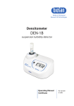
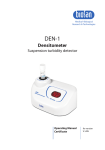
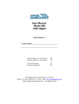
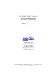
1
User’s Manual:
MODEL 904-T CLINOMETER PAK
Model 904-T Serial No. _______________
Bipolar Output (±2.5 volts typical):
Unipolar Output (0-5 volts typical):
Model 870 Readout Module Serial No. (optional) __________
© 2007 Applied Geomechanics Inc. All rights reserved.
140 Chestnut Street San Francisco, CA 94111
Phone: 415–364–3200 Fax: 415–861–1448 www.geomechanics.com
[email protected] • www.geomechanics.com
1. Introduction
B-97-1003, Rev. C
1
The Model 904-T Clinometer Pak is an economical biaxial inclinometer in a
rugged NEMA 4X (IP65) enclosure (Figure 1). It is suitable for a wide variety of
monitoring and measurement applications in the factory or laboratory, or under harsh
outdoor conditions. Tilt angles measured with the Model 904-T Clinometer Pak are
gravity referenced. For this reason, your Clinometer Pak will measure angular rotation in
any location and can be installed anywhere. There is no need for special shafts, linkages
or fixturing to obtain a useful reading.
The sensing element in the Clinometer Pak is an electrolytic tilt sensor, comprised
of a glass vial containing a conductive liquid and five platinum-clad electrodes. As the
sensor tilts, the liquid alternately covers and uncovers opposing electrodes, changing the
AC resistance measured along different paths through the sensor. The arrangement of the
four outer electrodes in four quadrants enables the electronics to resolve the direction and
magnitude of rotation in two orthogonal vertical planes (X and Y). The Clinometer Pak
electronics converts the raw AC signals to high-level DC voltage outputs that are sent
down the instrument’s cable. A temperature sensor also is included in your Clinometer
Pak. Output is a DC voltage proportional to temperature in degrees Celsius.
B-97-1003, Rev. C
2
2. Specifications
TILT OUTPUT
TEMPERATURE OUTPUT
TIME CONSTANT, T
NATURAL FREQUENCY
TEMPERATURE COEF.
POWER REQUIREMENTS
ENVIRONMENTAL
ENCLOSURE
CABLE
WEIGHT
ANGULAR
RANGE
SCALE FACTOR
RESOLUTION
REPEATABILITY
HYSTERESIS
LINEARITY
Two orthogonal tilt angles, ± 2.5 volts single-ended (standard), 0-5 volts available
0.1oC/mV, ±0.75oC accuracy; 0oC = 0 mV (bipolar output version), 0oC = 2.5 V (0-5 V
output version)
0.15 second
10 Hz
Span: +0.03%/ oC, Zero: 10-20 arc sec/ oC typ.
+8 to +24 VDC (bipolar output version) or +10.5 to +26.5 VDC (0-5 V output version) @ 7
mA, 250 mV ripple max., reverse polarity protected
-10 to +70 degrees C operating and storage, 100% humidity
Painted, NEMA 4X (IP65) aluminum box, 120 x 80 x 60 mm. Four 4.4 mm dia. mounting holes
at corners of 107 x 67 mm rectangle
10 ft (3 m) multiconductor cable with PVC jacket and tinned ends (longer cable available)
1 lb (0.4 kg)
Model 904-TH
High-Gain Version
Model 904-TS
Standard Version
Model 904-TW
Wide-Angle Version
±10 degrees
±25 degrees
±50 degrees
4°/ volt typical
0.005 degree of angle
0.01 degree
0.01 degree
1% of full span typical
10°/ volt typical
0.01 degree of angle
0.02 degree
< 0.02 degree
2.5% of full span typical
25°/ volt typical
0.02 degree of angle
0.04 degree
< 0.04 degree
7.5% of full span typical
(1.2% of half span)
Ordering Information
Model 904-TH
Model 904-TS
Model 904-TW
±10 degrees range
±25 degrees range
±50 degrees range
To add the following features, specify option code after Model Number
Option Code
Feature
0-5VUP
0-5 volt output
VISCDAMP
Critically damped sensor
P/N 70304
Additional cable, specify length
P/N 62204
6-pin male receptacle (connector) for clinometer cable
P/N 62202
6-socket in-line plug (mates to P/N 62204)
Model 870
Readout module (requires purchase of P/N 62204)
RMS225
Digital multimeter display unit (used with Model 870)
01439
Mounting bracket for vertical surfaces
01454-01
Mounting plate for horizontal surfaces
B-97-1003, Rev. C
3
Figure 1. Model 904-T Clinometer Pak
Figure 2. Enclosure and mounting hole dimensions
B-97-1003, Rev. C
4
3. Wire Color Code and Connector Pin Designations
Color coding of the wires in the Clinometer Pak cable is shown in Table 1. Pin
assignments refer to connector P/N 62204, which is available as an option and is attached
to the end of the clinometer cable. This connector is used for connecting the Clinometer
Pak to a Model 870 Readout Module, or whenever there is a quick connect/disconnect
requirement.
Table 1.
Wire Color Code and Connector Pin Designations
Function
Power
Signal Ground
Power Ground
X tilt
Y tilt
Temperature
Color
Red
White
Black
Green
Blue
Yellow
Pin (P/N 62204)
A
B
C
D
E
F
4. Grounding and Transient Protection
The signal cable of the Clinometer Pak contains two ground wires: A black
power ground wire and a white signal ground wire. Power and signal ground are
common on the internal printed circuit assembly. We recommend that the black wire be
connected to the ground of your power supply and that the white wire be connected only
to the signal ground of your recording device (digital voltmeter, A/D converter, etc.).
Under normal conditions, the two wires should be not be shorted together at the power
supply end. Keeping them separate prevents a voltage drop caused by current flowing in
the signal ground wire and keeps the reference potential the same at both ends of the
cable.
Your Clinometer Pak is reverse polarity protected but is not surge (transient)
protected. A high-voltage transient exceeding the 24 VDC input range could damage the
electronics.
5. Installing Your Clinometer Pak
The Clinometer Pak has four mounting holes (Figure 2) for fastening it to a P/N
01454-01 Mounting Plate (for horizontal surfaces), to a P/N 01439 Mounting Bracket
(for vertical surfaces), or directly to the surface to be monitored. These holes are 4.4 mm
(0.173 inch) in diameter and accept a no. 8 screw. Access to the mounting holes is by
removing the lid of the enclosure.
B-97-1003, Rev. C
5
For best results, install your Clinometer Pak in a shaded location away from
temperature extremes.
6. Converting Voltage Readings to Tilt Angles and Temperatures
The voltage outputs of the Clinometer Pak are quickly converted to tilt angles
using the scale factors or the polynomials in the Calibration Certificate at the end of this
manual. To use the scale factor, simply multiply the voltage reading by the scale factor.
For example, if the scale factor of the X channel is 10.06 degrees/volt, and the X output
is +2.000 volts, the tilt angle is +20.12 degrees (including the bias). To obtain tilt angles
from the polynomial, substitute your voltage reading for the variable V and use the listed
polynomial coefficients. Again, the computed angle includes the bias. Using the
polynomial eliminates most of the nonlinearity and gives the most accurate results. To
convert from degrees to other angle units (arc minutes, mm/meter, etc.), refer to Table 2.
The instructions in the paragraph above are for rotations in the one of the
principal planes of the Clinometer Pak, that is, in a vertical plane parallel to either the X
or the Y arrow on the label on the enclosure. Rotation in another vertical plane is termed
a “cross-axis tilt.” Computation of cross-axis tilt angles is described in Appendix A.
To obtain temperature in degrees Celsius from clinometers with bipolar output,
simply multiply the voltage reading on the temperature channel by 100oC/V (0.1oC/mV).
To obtain readings from clinometers with unipolar output, first subtract 2.5 volts from the
voltage reading, then multiply the result as above.
Table 2. Angle Conversion Chart
degrees
arc minutes
arc seconds
μradians
mm/meter
inches/ft
1
60
3600
17453
17.45
0.2094
arc minutes =
0.01667
1
60
290.9
0.2909
3.46x10⁻³
arc seconds =
2.78x10⁻⁴
0.01667
1
4.848
4.85x10⁻³
5.82x10⁻⁵
μradians =
5.73x10⁻⁵
3.44x10⁻³
0.2063
1
0.001
1.20x10⁻⁵
mm/meter =
0.0573
3.436
206.3
1000
1
0.0120
inches/ft =
4.775
286.5
17,189
83,333
83.33
1
degrees =
B-97-1003, Rev. C
6
7. Measuring and Removing Zero Offset (Bias)
Bias (B) is defined as the difference between the true angle and the angle reported by
the clinometer when it it level. Think of a perfectly horizontal surface with your Clinometer
Pak sitting on it. If there were no bias, the output would read 0 volts on both channels (or
2.5 volts for unipolar clinometers with 0-5 volts output). In reality, the outputs of most
clinometers are not 0 volts when level because of mechanical tolerances in the component
parts (sensor, screws, standoffs, etc.).
To measure and remove bias, do the following:
1. Place the clinometer on an approximately horizontal surface (table top, granite flat,
etc.). Read the output voltages VX1 and VY1 for each channel and then compute the
indicated angles θX1 and θY1 by multiplying by the scale factors for your clinometer,
found in Appendix B. For example, θX1 = VX1 x SX, where SX is the scale factor for
the X channel.
2. Rotate the tiltmeter 180 degrees on the surface so that it is facing the opposite
direction (Figure 3). Read the new output voltages VX2 and VY2 and compute the
angles θX2 and θY2 using the same procedure as in step 1 above. The scale factors are
the same for both steps.
3. The biases are given by the formulae BX = (θX1 + θX2)/2 and BY = (θY1 + θY2)/2.
Record these biases and subtract them from all subsequent measurements to get the
true angle.
Figure 3. Measure tilt angles in these two positions to compute clinometer bias.
B-97-1003, Rev. C
7
8. Using the Model 870 Readout Module
The Model 870 Readout Module may be used to power your Clinometer Pak
(units with bipolar output only) and switch the X and Y channel outputs to a digital
multimeter for display. If your Clinometer Pak was shipped with a Model 870 it will
have a 6-pin connector (P/N 62204) on the end of its cable. The connector on the end of
the Model 870 cable is P/N 62202. Skip this section if you did not purchase a Model
870.
The Model 870 Readout Module is designed for use with any hand-held
multimeter containing banana plug sockets with standard 0.75-inch center-to-center
spacing (Figure 4). To use the Model 870, first plug it into your clinometer cable via the
6-pin connector. Then plug the it into your multimeter via the banana jacks (red to red,
black to black). Set the multimeter to its DC Volts setting and turn it on. Turn the XOFF-Y switch on the Model 870 to the X or Y position (this powers the clinometer).
Now, depress the BATTERY CHECK button. If the voltage displayed on the multimeter
is below 8 volts, replace the battery inside the Model 870 with a new one as described in
the next section.
You are now ready to read your Clinometer Pak. Turn the toggle switch to X or
Y and read the output voltage on the multimeter display (the multimeter must be in its
DC Volts setting). The temperature channel cannot be read using the Model 870.
Figure 4. Model 870 Readout Module
B-97-1003, Rev. C
8
9. Model 870 Battery Replacement
If the voltage level of the Model 870 Readout Module battery drops below 8
volts, the battery should be replaced. The battery is a standard 9-volt radio battery,
available in most supermarkets and hardware stores. To replace the battery:
1. Remove the four metal screws from the back panel. Carefully separate the back panel
from the front portion of the Readout Module. Do not twist or pull the internal
wiring.
2. Replace the old battery with a fresh new battery.
3. Replace the back panel.
10. Warranty and Assistance
Standard goods (those listed in Applied Geomechanics’ published sales literature, excluding
software) manufactured by Applied Geomechanics Inc. (AGI) are warranted against defects
in materials and workmanship for twelve (12) months from the date of shipment from AGI’s
premises with the following exceptions: Series 900 analog or digital clinometers are
warranted against defects in materials and workmanship for 90 days from the delivery date.
AGI will repair or replace (at its option) goods that prove to be defective during the warranty
period provided that they are returned prepaid to AGI and:
(a) that the goods were used at all times for the purpose for which they were designed and in
accordance with any instructions given by AGI in respect of them,
(b) that notice is received by AGI within 30 days of the defects becoming apparent, and
(c) that return authorization is received from AGI prior to the goods being sent back.
Should goods be damaged in transit to the Purchaser, AGI will accept no liability unless the
Purchaser can show that such damage arose solely from AGI’s failure to pack the goods
properly for shipment.
Software products are warranted to perform substantially in accordance with their
documentation for 90 days following your receipt of the software. AGI and its suppliers do
not and cannot warrant the performance or results you may obtain by using the software or its
documentation.
In respect of goods or parts thereof manufactured by others and resold by AGI, AGI will pass
on to the customer the benefit of any guarantee or warranty received by AGI from the
original manufacturer insofar as such guarantee or warranty is assignable.
ANY OTHER CONDITIONS OR WARRANTIES WHETHER EXPRESS OR IMPLIED
BY STATUTE OR OTHERWISE ARE EXCLUDED. THE REMEDIES PROVIDED
HEREIN ARE THE BUYER'S SOLE AND EXCLUSIVE REMEDIES. APPLIED
GEOMECHANICS INC. SHALL NOT BE LIABLE FOR ANY DIRECT, INDIRECT,
SPECIAL, INCIDENTAL OR CONSEQUENTIAL DAMAGES, INCLUDING LOST
PROFITS OR LOST SAVINGS, WHETHER BASED ON CONTRACT, TORT, OR ANY
OTHER LEGAL THEORY. THIS WARRANTY EXTENDS ONLY TO THE ORIGINAL
PURCHASER AND IS EXPRESSLY IN LIEU OF ALL OTHER WARRANTIES,
B-97-1003, Rev. C
9
WHETHER OF MERCHANTABILITY OR FITNESS FOR ANY PARTICULAR USE,
AND OF ALL OTHER OBLIGATIONS AND LIABILITIES OF ANY KIND AND
CHARACTER. THERE ARE NO WARRANTIES WHICH EXTEND BEYOND THE
DESCRIPTION ON THE FACE HEREOF.
(a) AGI’s liability arising out of the sale of its goods is expressly limited to the repair and/or
replacement of defective parts or the cost of such repair and/or replacement.
(b) If software does not perform substantially in accordance with the documentation, the
entire and exclusive liability and remedy shall be limited to either, at AGI’s option, the
replacement of the software or the refund of the license fee you paid for the software.
(c) Liability for any other form of loss or damage is hereby expressly excluded.
(d) Customer shall indemnify AGI against any third party claim arising out of the use of
goods and/or services supplied by AGI, including any claim arising directly or indirectly
out of alleged negligence on the part of AGI, its employees, servants, representatives or
agents.
B-97-1003, Rev. C
10
Appendix A. Computation of Cross-Axis Tilts
Problem
1. Rotation occurs in a vertical plane parallel to direction C.
2. Find angle α, which defines C direction.
3. Find amplitude of rotation, θC.
Assumptions
Plan View
1. Planes XY and CD are initially horizontal.
2. Scale factors, SX and SY, for rotations in
vertical planes parallel to X and Y directions
are given.
3. Bias voltages, VXB and VYB, have been
determined. Bias voltages are the tiltmeter’s
X and Y outputs when it is perfectly
horizontal and are equal to VXB = (VX1 +
VX2)/2 and VYB = (VY1 + VY2)/2. See Section 7 for further explanation.
Solution
For rotation in the X or Y directions, rotation angle is given by θX = SX VX and
θY = SY VY where SX and SY are the scale factors presented in the user’s manual or
calibration certificate, VX is the measured X voltage minus VXB , and VY is the measured
Y voltage minus VYB .
For rotation in the C direction we can define new scale factors:
SC' = SX/cos α and SC″ = SY/cos (90o - α)
And the rotation angle in the C direction becomes:
θC = (SX/cos α) (VX)
θC = [SY/cos (90o − α)] (VY)
[1]
[2]
Equating [1] and [2] and solving gives:
(SXVX)/(cos α) = (SYVY)/cos (90o - α)
(SXVX)/(SYVY) = cos α/cos (90o − α) = 1/tan α
B-97-1003, Rev. C
11
α = tan -1 [(SYVY)/(SXVX)]
[3]
Substituting α in equation [1] or [2] along with the known values of SX and VX, or SY and
VY, gives the rotation angle θC.
Summary: Steps in Measuring Cross-Axis Tilt Angle, θC
1. Measure bias voltages, VXB and VYB , on both tilt channels.
2. Subtract VXB and VYB from measured voltages to obtain corrected outputs VX and VY
for use in eqns. [1] through [3].
3. Compute α from equation [3] using known scale factors SX and SY.
4. Compute θC from equation [1] or [2].
B-97-1003, Rev. C
12
Appendix B. Calibration Certificates
B-97-1003, Rev. C
13