1
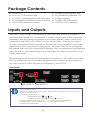
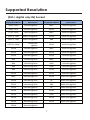
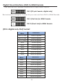
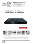
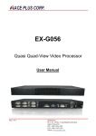
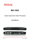
INSTRUCTION MANUAL
DVP14
Video Wall Processor
DVI Output
Cascadable
4 Output Displays
Dual-View
THIS PAGE IS LEFT
INTENTIONALLY BLANK
Safety and Notice
The DVP14 DVI output Cascadable Video Wall Processor,
4-Display Dual-View has been tested for conformance to
safety regulations and requirements, and has been certified
for international use. However, like all electronic equipment,
the DVP14 should be used with care.
Please read and follow the safety instructions to protect yourself from possible injury and to minimize the risk of damage to
the unit.
● Follow all instructions and warnings marked on this unit.
● Do not attempt to service this unit yourself, except where
explained in this manual.
● Provide proper ventilation and air circulation and do not
use near water.
● Keep objects that might damage the device and assure
that the placement of this unit is on a stable surface.
● Use only the power adapter and power cords and
connection cables designed for this unit.
● Do not use liquid or aerosol cleaners to clean this unit.
Always unplug the power to the device before cleaning.
1
Table of Contents
INTRODUCTION.............................................................3
FEATURES.......................................................................4
SPECIFICATIONS...........................................................5
PACKAGE CONTENTS..................................................6
INPUTS AND OUTPUTS...................................................6
SUPPORTED RESOLUTION.............................................7
HARDWARE INSTALLATION..........................................9
Installation Procedures ................................10
Connection Diagram ..................................11
OPERATION SOFTWARE.............................................12
System Requirement and Precautions ......12
Instruction of Software Connection ..........12
Instruction of Software Operation .............13
USING THE TV WALL CALCULATOR………………….17
TROUBLESHOOTING...................................................21
WARRANTY.................................................................22
2
INTRODUCTION
The DVP14 Cascadable Video Wall Processor, 4-Display DualView DVI Output is a powerful most cost effective, and fully
real time data/video processor for multiple flat panel displays
or projectors. With high-definition real-time DVI output, the
quality of the video wall is guaranteed. The output display
is scalable up to 255 by 255 squares.
Virtually any setup for the display layout may be possible by
the provided software. The DVP14 allows you to manipulate
two input videos, in any position and whatever sizes you want
for viewing. The embedded scaler converts signals from the
two input sources to match the native resolution of monitors,
flat panel displays, and/or projectors.
Also, there are user-selectable output settings up to WUXGA
(1920x1200). The DVP14 sends the resulting mixed video thru
DVI interface to the connected monitors/projectors based on
the display layout. The layout can be readily modified to fit
your applications and optimize visual effects. Typical applications include digital signage, Sport Bars, and broadcasting /
education / surveillance systems, etc.
This is a Video only processor and does not receive or output
any kind of audio.
3
Features
●
●
●
●
●
●
●
●
●
●
●
●
●
●
●
●
Four DVI outputs from 640x480 to 1920x1200
Local DVI loop output for monitoring the DVI input only
Supports HDMI, DVI, S-Video, CVBS, Component, and VGA
input, from 640x480 to 1920x1200, interlaced or progressive
Advanced video de-interlacing for improving 480i and 576i
SD video input
PIP (picture-in-picture), PAP or PBP (Picture by Picture), Full
screen modes and adjustable size & position through
software
Resize, position, flip, zoom output video
Perfect as a video screen splitter, a video converter and
a video switcher
Each DVI output has an independent controllable
display area
User-selectable output settings, up to 1920x1200
Can be cascaded to obtain larger display walls
Image parameters and layouts are automatically saved
in flash memory of the device and can be recalled for
later use
Several image parameters and layouts can be saved in the
controlling computer and can be loaded for later use
Software control through RS-232
Firmware upgradable for support of new features and
technology enhancements
Built-in factory reset switch
2RU size for compact rack installations
4
Specifications
Model Name
DVP14
Technical
Typical usage
Output displays
Input Format
Support
Video-wall processor
4
HDMI / DVI / VGA / YPbPr / S-Video / CVBS
[One digital and one analog can be used in PIP or PAP mode]
Output Support
DVI (HDMI by adapter)
Video loop-out
Yes, DVI
HDCP compliance
No
Video bandwidth
Video support
Audio support
HDMI / DVI [Single-link 4.95Gbps] VGA [165MHz]
Up to 1920x1200@60 / 1600x1200@60
Control
No
RS-232
PIP/PAP
Cascadable
Yes
Yes
Input TMDS signal
1.2 Volts [peak-to-peak]
Human body model — ± 19kV [air-gap discharge]
& ±12kV [contact discharge]
ESD protection
PCB stack-up
6-layer board [impedance control — differential 100Ω; single 50Ω]
1x DVI + 1x VGA + 1x RS-232 1XS-Video, 1XCVBS
4x DVI
DVI-I [29-pin female, digital only]
Input
Output
DVI connector
VGA connector
HD-15 [15-pin D-sub female]
RS-232 connector
DE-9 [9-pin D-sub female]
75Ωfemale
RCA connector
RJ-45 connector
WE/SS 8P8C with 2 LED indicators (Not in use)
Mechanical
Housing
Dimensions
[L x W x H]
Weight
Metal enclosure
1'10" x 1'5" x 3. 5" [550 x 440 x 88mm]
Model
Package
1'11" x 1'8" x 9.1" [592 x 500 x 230mm]
Carton
1'11" x 1'8" x 9.1" [592 x 500 x 230mm]
Model
Package
Fixedness
Power supply
Power consumption
Operation temprature
Storage temprature
Relative humidity
17.4 lbs [7900g]
20.9 lbs [9500g]
2RU rack-mount with ears
AC Power 100-240V
30 Watts [max]
32~95°F [0~35°C]
-4~140wF [-20~60°C]
20~90% RH [no condensation]
5
Package Contents
●
●
●
●
●
1x DVP14
1x UL AC C13 power cord
1x VGA to component breakout cable
1x Composite, S-video breakout cable
1x DVI/VGA breakout cable
●
●
●
●
●
1x Rack-mounting ear set
1x Installation software CD
1x User Manual
1x USB to RS-232 cable
1x DVI to VGA adapter
Inputs and Outputs
The DVP14 can use up to two inputs at one time and supports multiple input interfaces (HDMI, DVI, composite, S-Video, component, VGA (adapters
needed)) and accepts both graphics and video signals, which come from
computers and NTSC / PAL video sources respectively. There is a concept
of main channel and sub channel for this device. You can select one of the
digital inputs and one of the analog inputs, and then the DVP14 will display
the mixed video on the connected 4 displays. With an advanced de-interlace
function built in, low resolution but popular video formats such as NTSC / PAL
will be improved.
The drawing below shows the rear panel connectors for the video inputs of a
DVP14. Please see the Connection Diagram later in this manual to see how
you can connect video devices and displays to the DVP14.
Rear Panel
SEE NOTE: 2
SEE NOTE: 1
1. Factory Reset switch:
Default: Turn on the DVP14 then switch both switches simultaneously up and down
to factory default mode.
2. Firmware Update Switch:
Normal operation:
OFF,
OFF
Firmware update mode:
DOWN,
DOWN
This Input, Outputs ports support a variety of resolutions from 640x480 up
to 1920x1200, for more information on the supported resolutions,
see "Supported Resolution".
6
Supported Resolution
[DVI-I digital only IN] Socket
Supported Mode
Resolution
Supported Mode
Resolution
480p / 525p
720x483 @60Hz
MAC
832x624 @75Hz
480p (16:9)
960x483 @60Hz
VESA
1024x768 @60Hz
576p / 625p
720x756 @50Hz
MAC
1024x768 @60Hz
(HDTV) 720p
1280x720 @50Hz
VESA
1024x768 @70Hz
(HDTV) 720p
1280x720 @60Hz
IBM
1024x768 @72Hz
(HDTV) 1080p
1920x1080
@30Hz
VESA
1024x768 @75Hz
VESA
720x400 @85Hz
MAC
1024x768 @75Hz
VESA
640x350 @85Hz
VESA
1024x768 @85Hz
VESA
640x400 @85Hz
VESA
1152x864 @75Hz
IBM
720x400 @70Hz
MAC
1152x870 @75Hz
IBM
720x350 @70Hz
SUN
1152x900 @66Hz
IBM
640x350 @70Hz
SUN
1152x900 @76Hz
IBM
640x400 @70Hz
VESA
1280x960 @60Hz
VESA
640x480 @60Hz
VESA
1280x960 @85Hz
MAC
640x480 @67Hz
VESA
1280x1024 @60Hz
VESA
640x480 @72Hz
HP
1280x1024 @60Hz
VESA
640x480 @75Hz
IBM
1280x1024 @67Hz
VESA
640x480 @85Hz
HP
1280x1024 @72Hz
VESA
800x600 @56Hz
VESA
1280x1024 @75Hz
VESA
800x600 @60Hz
SUN
1280x1024 @76Hz
VESA
800x600 @72Hz
VESA
1600x1200 @60Hz
VESA
800x600 @75Hz
VESA
1920x1200 @60Hz
VESA
800x600 @85Hz
7
Digital Visual Interface (DVI) to HDMI Female
The unit has DVI-I Female connectors for Input and Outputs:
DVI-I [29-pin Female, digital only]
Recommended Adapter Connector you can use from DVI to HDMI Female
DVI-I (Dal Link) to HDMI Female
DVI-D (Dual Link) to HDMI Female
[DVI-I digital only Out] Socket
Supported
Mode
Resolution
(HDTV) 720p
1280x720 @50Hz
(HDTV) 720p
1280x720 @60Hz
(HDTV) 1080p
1920x1080 @60Hz
VESA
640x480 @60Hz
VESA
800x600 @60Hz
VESA
1024x768 @60Hz
VESA
1152x864 @75Hz
VESA
1280x1024 @60Hz
VESA
1280x1024 @50Hz
Supported
Mode
Resolution
VESA
1280x768 @60Hz
VESA
1366x768 @60Hz
VESA
1400x1050 @60Hz
VESA
1400x1050 @50Hz
VESA
1152x864 @75Hz
VESA
1600x1200 @60Hz
VESA
1920x1200 @50Hz
VESA
1920x1200 @60Hz
8
Hardware Installation
Safety Precautions
1. To prevent fire or shock hazards, do not expose this device
to rain or moisture.
2. When connecting other products such as DVD players,
and personal computers, you should turn off the power of this
product and the other devices for protection against electric
shocks.
3. The product should be placed more than one foot away
from heat sources such as radiators, heat registers, stoves, and
other products (including amplifiers) that produce heat. In addition, do not place any material or devices on the top of the
device.
4. Do not use immediately after moving from a low temperature to high temperature, as this causes condensation,
5. Do not place this product on an unstable cart, stand, or
table. The product may fall, causing serious injury to a child or
adult and serious damage to the product.
6. Unplug this product from the wall outlet before cleaning. Do
not use liquid cleaners or aerosol cleaners. Use a damp cloth
for cleaning.
7. Do not allow the same still picture to be projected for a long
time or an abnormally bright video picture to be projected.
The video image could be burned in to the display device.
9
Installation Procedures
Unpacking
Remove the DVP14 from the shipping box and examine it for any
signs of shipping damage or missing items (check with package
contents above). All shipping items should be saved if the product
is to be moved or returned for service. Shipping unit back to CE
labs or dealer for service not in the original box may result in
voiding warranty or additional cost.
Placement
Please do not block the sides of this device or stack another device on the top or bottom of the DVP14. Allow sufficient distance
to adjacent equipment to allow proper ventilation airflow.
Connections
We recommend the highest quality cables for both input and
output connections.
1. Turn off the DVP14 and all devices that will be connected
to the DVP14.
2. Connect up to 4 monitors, projectors or other displays that
comes with DVI inputs by using male-to-male DVI cables to
the DVP14 DVI outputs.
3. Connect a device equipped with DVI output (such as PC)
to the DVI input connector of the DVP14.
4. Connect your controlling computer with the DVP14 by a
9-pin RS-232 adapter and then install the software.
5. Turn On the DVP14.
6. Turn On all devices connected to the DVP14 and then set
up the display output through RS-232 and the software
included with the unit.
10
Connection Diagram
9
11
OPERATION SOFTWARE
System Requirement and Precautions
1. After turning off the DVP14; please wait at least 15 seconds
to allow the power capacitors to be discharged before
reapplying power.
2. The DVP14 comes with a software control program which
runs under Microsoft Windows 98, 2000, XP. The application
controls the DVP14 through a RS-232 serial data control interface.
3. Before you run the software please, make sure you have a
RS-232 cable connected between your computer COM port
and the DVP14.
4. To make sure all information shown in the software display
is synchronized with those in the device; please click "Connect"
to acquire the latest data from the DVP14.
*** NOTE: The Software is the same for the DVP14 & DVP19 ***
Instructions for Software Connection
1. Turn on the DVP14. The front panel Display will be blink
one time. Make sure the serial port (RS-232) connection
is secured.
2. The first step after running the software is automatic detection of the DVP14. If the DVP14 responds correctly through
RS-232 port, the computer will show the main control
panel. The process takes 5 to15 seconds. If the response is
not accurate, a warning window will show up as follows.
There are a couple of possible reasons causing the lack of
communications:
•The DVP14 is not powered on.
•The DVP14 been ON with no activity for a long period of
time and may enter a sleep state. Please check the current status, and reboot the DVP14.
•The RS-232 cable maybe loose or some other software
has taken the available serial port. Please make sure the
RS-232 cable is connected and the available serial port is
free to be used by the DVP14 software.
12
Software Operation
Main Control Panel
State
Overall state and format setting:
1. Save and Read: The current layout
of the four DVI outputs ports can be
saved to a file. In addition, the file can
be uploaded in the future to restore
the setting.
2. Display Setting / Aspect Ratio: The
main and sub sources both can be adjusted to 16:9 or 4:3. The brightness and
contrast of the mixed video also can
be adjusted for different requirements.
After setting, please press
Update Setting to save the change.
3. Firmware Ver.: To display the current
firmware version of the device.
4. Color Balance: The color of the
video can be automatically adjusted.
But it works only when the source is
analog and the mode is Full Screen.
5. Factory Reset
6. Set All Output Resolution
13
Setting
Use this button to configure the correct COM port for serial control,
and the device ID for identification.
Connect
Establish communications with the DVP14 and the computer.
Disconnect
Disconnect the computer COM port from the DVP14.
Input Resolution
Setting the resolution of the input port.
1. After 10 secongs, the new setting can be applied to the DVP14,
but the input source and Display layout mode will return to default.
2. Please reset input source and Display layout mode.
Main Source
Choose one of the inputs as the main source
Sub Source
Choose oneof the inputs as the sub source
Display Layout Mode
Configure the layout of the main and sub sources in the mixed video.
1. Main Full Screen: Only main source is displayed in the
mixed video output.
2. Sub Full Screen: Only sub source is displayed in the
mixed video output.
3. PIP Mode: The main source is displayed as the background,
and the sub source is placed in a window.
4. Side by Side: The main source and sub source are displayed
at the same size, side by side.
5. Custom Define PAP: User can adjust the layout of the two inputs
source to different sizes on the output.
Main and Sub source can be from the same input.
14
Setup Individual Output DVI ports (Channel)
There are a total of 4 DVI output ports for theDVP14. Each DVI output
can be independently set up to display any area of the input video.
Each output can be set to a different output resolution to adapt
different combinations of monitors or projectors.
Display Output
Display Output 1
Display Output 2
Display Output 3
Display Output 4
To select each individual DVI output port to setup with preferable
output, please click on the desired
output as shown to the left, and the
control dialog window shown below
will show up accordingly!
4 1 2 5 3 6 For each output display, users can define which area of the input
video is to be displayed on that screen. First, setup the X Total and
Y Total, and then define the upper-left (X Start, Y Start) and bottomright (X End, Y End) corners for each display channel. The control
panel to achieve this goal is as shown.
15
1
2 3 This screen representation area will demonstrate the resulting
selection of the input video to be displayed for the selected
DVI output port.
"Original Input Video" shows the resolution information of the
input video to each output channel, and it will vary depending upon the input video.
"Original Resolution" Section Setup the output resolution for
individual DVI output port. Notice that each display can run
at a different resolution to adapt to different resolutions from
different panels.
Check "Capture Mode Enable" will enable the scaling parameters. This monitor will now display the video region as
defined by the output scaling parameters. If users disable
this section, this output channel will display simply the full
display of the input video.
Check "Auto Apply Settings" will automatically load the
new settings into processor.
Select “Update Status” will refresh the information of the
output video parameters.
Select “Update Apply Settings” will load the parameters
into processor.
While “Auto Apply Settings” is checked, parameter
updates are automatically sent to the processor.
4
Define Area Setting – Select the X Total, Y Total, Upper-left
X, Y point coordinates using scroll bars or manually keying in
this section accordingly. This section will roughly define capture area for the input which is needed for each individual
channel. The resulting capture area corresponds to the input
video will be illustrated in the screen representation area. 1 16
5 “Fine Tune by Percentage” will provide the option to further
adjust the position and area defined in 4 .
For outward expansion
For inward reduction
By percentage, users need to determine what will be the reference. There are two choices for this part: "Specified Area"
and "Fulll Input". Normally, "Specified Area" will work more
appropriately while users are dealing with panel bezels;
because the overlapped masking area will be close the
specified area instead of full input video!
6 "Fine Tune by Pixel" offers similar approach to adjust the position and area of the output channel.
The idea behind this section is the same to “Fine Tune by Percentage”. The difference is that the adjustment is based on
pixels. Users can therefore adjust the output channel area
pixel wise.
Using the TV wall Calculator
1. Verify that the sequence of the ports are connected as shown below:
(We recommend this sequence, but you can connect the sequence the way it works best for you)
One screen will show 1/4 image for the default settings of the DVP14
17
Using the TV wall Calculator Continued
2. Open the Software DVP14 video wall processor and select the TV Wall
Calculator, under the Connect selection:
3. Measure the length and height of the screen as shown below and fill
in the boxes in the Calculator (inch) Section, then Select the
configuration. Select 2x2. Then Select "Calculate".
18
4. When you are finished, this window will pop up.
Pess OK. Click X to close the "TV Wall Calculator"
window.
5. On the Display Output section, Select: Display Output 1, and you will
see that the data has changed automatically.
Then press: (2) Write setting to device.
6. On the Display Output section, Select: Display Output 2, and you will
see that the data has changed automatically.
Then press: (2) Write setting to device.
Repeat this step for Output #3 and Output #4.
Output #5, #6, #7, #8 and #9 are for the DVP19 ONLY – Not used on the DVP14
19
7. After you press: Write setting to device. From Port #1 to Port #4, you will
see the video wall.
8. The margins will be very close.
If you are not satisfied, go back to Step #5 to fine-tune the yellow marked
data to get a smoother image between screen to screen. Do this adjustment
on each screen as needed.
Remember push "Write setting to Device" each time you make an adjustment.
20
TROUBLESHOOTING
Problem
No power
Recommendations
•
•
No or Erratic Video
•
•
•
Poor quality
•
•
Wrong color
•
Check the AC power cord to ensure proper
insertion into the DVP14 and at the wall
socket. If using a power strip, verify switch is
on and the circuit breaker is not tripped.
If you are recovering from a power outage or
intentional AC power disconnection, leave
the device off for a minute and then power it
on again.
Make sure all cables are in good condition
and prop¬erly connected to the DVP14, the
sources, and the displays.
Configure the output video resolution so that
it does not exceed the native resolution of
the display. ( in this case, the message of “out
of range” is usually showed on your display
screen)
Every time when you change the input resolution, please wait for 10-20 seconds. After the
resolution is changed, the selection of input
and the Display layout mode will return to
default. So, please adjust the input source
and Display layout mode to your requirement
once again.
When VGA input is used for the first time, it
will take up to 10 seconds to display the VGA
source successfully.
We suggest that don’t use Y-cables to split
your video source. That will low¬er output
video quality. Use a distribution amplifier
instead of Y-cables.
Make sure the video source is not compressed and maintains the highest native
resolution.
Press “Color Balance” key in “State” for auto
configuration.
Auto color configuration only works at VGA
and component inputs.
No Data Connection
•
When unable to achieve serial port connection, please reboot the DVP14. If this does
not fix the issue, check the configuration of
the computer serial port and verify the serial
cable is connected properly.
21
WARRANTY
The SELLER warrants the DVP14 DVI output, Cascadable, Video wall
Processor, 4-Display Dual-View to be free from defects in the material and workmanship for 1 year from the date of purchase from the
SELLER or an authorized dealer. Should this product fail to be in good
working order within the 1 year warranty period, the SELLER, at their
option, will repair or replace the unit, provided that the unit has not
been subjected to accidental damage, disaster, static discharge
and power surge, abuse or any unauthorized modifications. This
warranty is offered by the SELLER for its BUYER with direct transaction
only. This warranty is void if the warranty seal on the metal housing is
broken.
A unit that fails under conditions other than those covered will be repaired at the current price of parts and labor in effect at the time of
repair. Such repairs are warranted for 90 days from the day of reshipment to the BUYER. If the unit is delivered by mail, customers agree
to insure the unit or assume the risk of loss or damage in transit. Under
no circumstances will a unit be accepted without a Return Authorization Number (RMA #).
This warranty is in lieu of all other warranties expressed or implied,
including without limitations, any other implied warranty, or suitability,
or merchantability for any particular purpose, all of which are expressly disclaimed.
Proof of sale may be required in order to claim warranty. Customers outside USA are responsible for shipping charges to and from the
SELLER. Cables and power adapters are limited to a 30 day warranty
and must be free from any markings, scratches, and neatly coiled.
22
The content of this manual has been carefully checked and is believed to be accurate. However, The SELLER assumes no responsibility for any inaccuracies that may be contained in this manual. The
SELLER will NOT be liable for direct, indirect, incidental, special, or
consequential damages resulting from any defect or omission in this
manual, even if advised of the possibility of such damages. Also, the
technical information contained herein regarding the DVP14 features and specifications is subject to change without further notice.
CE labs
3209 Wood Drive.
Garland, TX 75041
(469) 429-9200
(800) 767-6189
Fax: (469) 429-9205
23
INSTALLER NOTES
Purchasing Date:
S/N:
24
INSTALLER NOTES
Purchasing Date:
S/N:
25
CE labs can support many areas of your audio and video
distribution needs.
We manufacture:
• Digital Signage software and Media Players
• HD Matrix Switchers
• RF amplifiers
• HDMI and Component HD distribution amplifiers
• CAT 5 Signal Extenders
• VGA Extenders and Splitters
• and cables of all types.
See our full product line at www.celabs.net
WARRANTY
Cable Electronics, Inc. warrants this product to be free from defects in
material and workmanship, under normal use and service, for a period of
one year from the purchase by the original purchaser. If this product is
defective or malfunctions, Cable Electronics will replace or repair this unit (at
their option) within a reasonable time. No expressed or implied warranty is
made for any defects caused by immersion or exposure to liquids, abuse,
neglect, improper operation of unit, excess wear and tear and defects
resulting from unauthorized disassembly and or modification.
3209 Wood Drive
Garland, TX 75041
Phone: (469) 429-9200
Toll free: (800) 767-6189
Fax: (469) 429-9205
www.celabs.net
Document:
900-5067-01 Rev. A