1
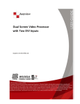
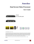
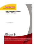
KVM Quad Screen Video Multiviewer With IR, Keyboard and Mouse Control Model #: DVI-SPLITPRO-4X © 2013 Avenview Inc. All rights reserved. The contents of this document are provided in connection with Avenview Inc. (“Avenview”) products. Avenview makes no representations or warranties with respect to the accuracy or completeness of the contents of this publication and reserves the right to make changes to specifications and product descriptions at any time without notice. No license, whether express, implied, or otherwise, to any intellectual property rights is granted by this publication. Except as set forth in Avenview Standard Terms and Conditions of Sale, Avenview assumes no liability whatsoever, and disclaims any express or implied warranty, relating to its products including, but not limited to, the implied warranty of merchantability, fitness for a particular purpose, or infringement of any intellectual property right. Reproduction of this manual, or parts thereof, in any form, without the express written permission of Avenview Inc. is strictly prohibited. www.avenview.com|1 Table of Contents Section 1: Getting Started ...................................................................................................................... 4 1.1 Important Safeguards ............................................................................................................ 4 1.2 Safety Instructions ................................................................................................................. 4 1.3 Regulatory Notices Federal Communications Commission (FCC) ......................................... 5 1.4 Introduction ........................................................................................................................... 5 1.5 Package Contents................................................................................................................... 6 1.6 Before Installation.................................................................................................................. 7 1.7 Panel Description ................................................................................................................... 8 1.7.1 DVI-SPLITPRO-4K Front and Rear Panel ................................................................................ 8 1.8 Installation ............................................................................................................................. 9 1.8.1 Installation to Control 1-4 PC’s via USB ................................................................................. 9 1.8.2 Default display modes for KVM hot key control .................................................................. 10 1.9 Software Installation and Setup .......................................................................................... 10 1.9.1 System Requirements .................................................................................................. 10 1.9.2 Software Connection .................................................................................................... 11 1.9.3 Software Operation ...................................................................................................... 13 1.9.4 Software Configuration ................................................................................................ 23 Section 2: Cascade Installation............................................................................................................. 24 2.1 The Control Serial................................................................................................................. 24 2.2 Converter Serial ................................................................................................................... 25 Section 3: Front Panel Controls ............................................................................................................ 28 3.1 Front Panel Push Buttons Description ................................................................................. 28 3.2 Front Panel Push Buttons Functions .................................................................................... 29 3.2.1 Selecting PIP Window Arrangement ............................................................................ 29 3.3 On Screen Display Menu ...................................................................................................... 30 3.4 IR Remote Control................................................................................................................ 31 Section 4: Specifications....................................................................................................................... 32 4.1 4.1.1 Supported Resolutions......................................................................................................... 33 DVI / Component / VGA ............................................................................................... 33 www.avenview.com|2 4.1.2 4.2 DVI-OUT........................................................................................................................ 33 General Troubleshooting ..................................................................................................... 34 www.avenview.com|3 Section 1: Getting Started 1.1 Important Safeguards Please read all of these instructions carefully before you use the device. Save this manual for future reference. What the warranty does not cover Any product, on which the serial number has been defaced, modified or removed. Damage, deterioration or malfunction resulting from: Accident, misuse, neglect, fire, water, lightning, or other acts of nature, unauthorized product modification, or failure to follow instructions supplied with the product. Repair or attempted repair by anyone not authorized by us. Any damage of the product due to shipment. Removal or installation of the product. Causes external to the product, such as electric power fluctuation or failure. Use of supplies or parts not meeting our specifications. Normal wear and tear. Any other causes which does not relate to a product defect. Removal, installation, and set-up service charges. 1.2 Safety Instructions The Avenview DVI-SPLITPRO-4K Advanced Quad Screen Video Processor has been tested for conformance to safety regulations and requirements, and has been certified for international use. However, like all electronic equipment’s, the DVI-SPLITPRO-4K should be used with care. Read the following safety instructions to protect yourself from possible injury and to minimize the risk of damage to the unit. Do not dismantle the housing or modify the module. Dismantling the housing or modifying the module may result in electrical shock or burn. Refer all servicing to qualified service personnel. Do not attempt to service this product yourself as opening or removing housing may expose you to dangerous voltage or other hazards Keep the module away from liquids. Spillage into the housing may result in fire, electrical shock, or equipment damage. If an object or liquid falls or spills on to the housing, unplug the module immediately. Have the module checked by a qualified service engineer before using it again. Do not use liquid or aerosol cleaners to clean this unit. Always unplug the power to the device before cleaning. www.avenview.com|4 1.3 Regulatory Notices Federal Communications Commission (FCC) This equipment has been tested and found to comply with Part 15 of the FCC rules. These limits are designed to provide reasonable protection against harmful interference in a residential installation. Any changes or modifications made to this equipment may void the user’s authority to operate this equipment. 1.4 Introduction Avenview DVI-SPLITPRO-4K KVM Quad Screen Multiviewer with IR, Keyboard and Mouse is an advanced video processor for most multimedia presentations. This unit is an ideal solution for applications where four video signals must be displayed on a single display. It supports up to 16 types of video inputs, of which four can be outputted simultaneously with the desired display layout through software control. The advanced video processor allows you to manipulate the output images to various sizes and multiple positions on the desired display. This unit can controlled with the ease of the front panel buttons, IR remote and RS232 via a cable or control system, this functionality allow the user to easily set the desired outputs by 5 preset layouts or 8 custom layouts saved by the user. Avenview DVI-SPLITPRO-4K is also equipped with a Master PS/2 Keyboard and Mouse Control. With this feature, users can switch Keyboard and Mouse Control among 2 to 4 PC sources and control the individual PC with the interactive USB connectors with software available for download. The embedded scalar converts signals from input sources to match the native resolution of monitors, flat panel displays, projectors as well as user-selectable output settings up to WUXGA (1920x1200). Dual outputs are provided in both analog (VGA) and digital (DVI) format, one is connected to remote display and the other is connected to on-site display for real time monitoring. - Support Six most popular video formats: four VGA, four DVI/HDMI, four component, four S-Video and four composite inputs Input resolution support from 640x480 to 1920x1200, interlaced or progressive. DVI & HDMI Support HDCP Dual outputs (DVI / VGA), 640x480 to 1920x1200. 4 Port Keyboard / Mouse Control with PS/2 Input and USB Outputs Video background available. Adjustable size & position through software. Dynamic transition for video sizing and positioning Titles, borders and colored backgrounds. Resize, position, zoom & pan and blend output video. Image parameters and layouts are automatically saved in flash memory and can be recalled for later use. Several Image parameters and layouts can be saved in computers and can be loaded for later use. Video parameters adjustable (brightness, contrast, color temperature, etc.). User-selectable output settings, up to 1920x1200. Use as a Video Splitter, a Video Converter and a Video Switcher. Firmware upgradable for support of new features and technology enhancements. Control through RS-232/RS-485 over Cat-5 and IR Remote Control Can be cascaded to obtain more images using RS-485 control path Control protocol available for customer proprietary design 1RU Size www.avenview.com|5 1.5 Package Contents Before you start the installation of the converter, please check the package contents. - DVI-SPLITPRO-4K DVI – DVI & VGA breakout Cable VGA to Component breakout Cable DVI to VGA Adapter Rack Mounting Kit RS232 to USB Adapter IR Remote Control Software CD AC Power Supply User’s Manual x1 x4 x4 x4 x1 x1 x1 x1 x1 x1 www.avenview.com|6 1.6 Before Installation Put the product in an even and stable location. If the product falls down or drops, it may cause an injury or malfunction. Don’t place the product in too high temperature (over 50°C), too low temperature (under 0°C) or high humidity. Use the DC power adapter with correct specifications. If inappropriate power supply is used then it may cause a fire. Do not twist or pull by force ends of the optical cable. It can cause malfunction. Avenview DVI-SPLITPRO-4K has 16 inputs and accepts both graphics and video signals, which come from computers (DVI or VGA), composite, and component video sources respectively. You can pick up four of the ten inputs and then display four of them simultaneously on the same screen. Connectors Input Output Keyboard / Mouse Connector DVI, Component, VGA, Composite, S-Video DVI-I OUT Keyboard Mouse I/O Video Source DVI HDMI (DVI to HDMI Cable or Adapter)*NOT SUPPLIED* VGA (DVI to VGA Adapter) Component (YPbPr) (DVI to VGA Adapter and VGA to Component Adapter) Composite S-Video Display 1 x DVI Display VGA Display (DVI to VGA Adapter) 1 x DVI Display & 1 x VGA Display (through DVI to DVI/VGA Y Cable) 2 x PS/2 Compatible Keyboard and Mouse 4 x USB Output connected up to 4 PC www.avenview.com|7 1.7 Panel Description Avenview Advanced Quad Screen Video Processor (DVI-SPLITPRO-4K) has 16 inputs and accepts both graphics and video signals, which come from computers (DVI or VGA), composite, and component video sources respectively. You can pick up four of the ten inputs and then display four of them simultaneously on the same screen. 1.7.1 DVI-SPLITPRO-4K Front and Rear Panel No# 1 3 5 7 9 11 13 15 17 Description CONTROL PANEL CONTROL BUTTONS (UP,DOWN,LEFT,RIGHT) POWER SWITCH S-VIDEO/CPOMPOSITE INPUT PS/2 MOUSE USB (PC 1-4 CONTROL) SERIAL CONTROL (RS232) RS484 (CASCADE) VGA OUTPUT No # 2 4 6 8 10 12 14 16 18 Description IR SENSOR INFORMATION DISPLAY POWER SUPPLY 100-240V DVI/HDMI/VGA/COMPONENT INPUT PS/2 KEYBOARD USB to PC SWITCH MODE SETTING MODE SETTING DVI/HDMI OUTPUT To reset the DVI-SPLITPRO-4K to factory default settings: Turn on the DVI-SPLITPRO-4K then switch both DIP Switches simultaneously up and down to reset the unit to factory default settings www.avenview.com|8 1.8 Installation To setup Avenview DVI-SPLITPRO-4K follow these steps for connecting to a device: 1. 2. 3. 4. 5. 6. 7. 8. 9. 10. 11. 12. 13. Mount or fix the DVI-SPLITPRO-4K safely Switch off DVI-SPLITPRO-4K and all source devices and displays that will be connected Connect a monitor, projector, other displays that come with DVI / VGA inputs by using 1 male – male DVI cable to DVI-SPLITPRO-4K DVI output. (you can connect 2 displays equipped with DVI and VGA respectively by DVI – DVI/VGA Y cable Plug-in DVI to DVI/VGA breakout cable to DVI-Component-VGA and plug in VGA to Component adapter to VGA connector of the breakout cable Connect a device equipped with DVI output (such as PC) to the DVI connector of the breakout cable Connect a device equipped with the component video output to 3-RCA jack of the Component video adapter Connect a device with VGA output (such as laptop) to VGA connector of DVI-SPLITPRO-4K Connected a device with Composite or S-Video video output to composite input of DVI-SPLITPRO-4K through S-Video / Composite Y cable. Connect the USB Cable(s) between DVI-SPLITPRO-4K and computer(s) Connect your computer to DVI-SPLITPRO-4K via RS232 to USB Adapter cable and then install the software Turn ON DVI-SPLITPRO-4K Run the Control Software and establish the connection between PC and DVI-SPLITPRO-4K Turn ON all connected devices and then control the display output thru RS232 and included software 1.8.1 Installation to Control 1-4 PC’s via USB 1. 2. 3. 4. Follow instructions 1-11 before attempting to control PC control Connect one set of PS/2 compatible Keyboard and Mouse if any control to computer(s) is necessary Connect the USB Cable(s) between DVI-SPLITPRO-4K and computer(s) located on the rear panel Download software PS2 to USB Driver from downloads section. www.avenview.com|9 1.8.2 Default display modes for KVM hot key control Full Quad1 Quad2 * Red Icon implies the main display area. Key Combination1 Ctrl + Alt + Shift + 1 Ctrl + Alt + Shift + 2 Ctrl + Alt + Shift + 3 Ctrl + Alt + Shift + 4 Ctrl + Alt + Shift + 5 Ctrl + Alt + Shift + 6 Ctrl + Alt + Shift + 7 Ctrl + Alt + Shift + 8 Ctrl + Alt + Shift + 0 1.9 Function Description Keyboard & mouse control granted to computer #1 Keyboard & mouse control granted to computer #2 Keyboard & mouse control granted to computer #3 Keyboard & mouse control granted to computer #4 Switch Video #1 to the main display area Switch Video #2 to the main display area Switch Video #3 to the main display area Switch Video #4 to the main display area 4 Mode switching between Full, Quad1, Quad2, Quad3 Software Installation and Setup 1. Hotkey definitions are based on IBM PS/2 compatible keyboard and the Ctrl, Alt, and Shift keys are on the LEFT side of the keyboard. 2. Switching video source to the main display area will bring MX-1004K back to one of the video default layouts as shown above. 3. While the control software is adjusting the video layout, the keyboard and mouse control will be off. 4. User can define Quad3 through the software 1.9.1 1. 2. 3. 4. 5. System Requirements The DVI-SPLITPRO-4K provides a software control program which runs under Microsoft Windows 98, 2000, XP, Vista, 7 through the interface of RS-232 serial control. Before you click on the icon of the software, make sure you have secured the connection between your computer COM port and the DVI-SPLITPRO-4K. Install driver for RS232 to USB adapter Once DVI-SPLITPRO-4K is turned on, it display green LED light Ensure that correct driver for RS232-USB Adapter (included with DVI-SPLITPRO-4X/K) are installed. You can check “Device Manger” under “Ports” page to check if drivers are installed correctly www.avenview.com|10 1.9.2 Software Connection 1. 2. Power up the DVI-SPLITPRO-4K and you can see VFD on the front panel blink. . Launch Avenview Control Software. It will open following “Serial Port” setting page. 3. Click on Scan button and it will automatically detect Avenview Video Processor and display the following screen: 4. Note the “Device – ID” and Select Correct “Com Port” and Device ID” from bottom of screen. Once Correct “Com Port” and “Device ID” is selected, it will change “Device Modular Error” to “Device Ready” as shown below: www.avenview.com|11 5. Once Device is Ready, click “OK” and Avenview Control Software will launch . www.avenview.com|12 1.9.3 Software Operation The software has following menu options available: 1 2 3 4 5 6 7 8 9 10 1 Fast Linkage This button will update software GUI for device state 2 Output Resolution Supported Mode HDTV 720p HDTV 1080p VESA VESA VESA 3 Resolution 1280x720 @ 60Hz 1920x1080 @ 60Hz 800x600 @ 60Hz 1024x768 @ 60Hz 1280x1024 @ 60Hz Supported Mode VESA VESA VESA VESA VESA Resolution 1280x768 @ 60Hz 1366x768 @ 60Hz 1400x1050 @ 60Hz 1600x1200 @ 60Hz 1920x1200 @ 60Hz Background Color Clicking on this button will show the color dialog for background color adjustment. 4 www.avenview.com|13 Background Setting DVI-SPLITPRO-4K offers the video background to make this advanced unit actually working like 5 channel video mixer! The default background video must work as full screen! Users can choose between color and video background through the following control window. Click on this button will show the dialog for output resolution, background color and background channel setting. We recommend not changing Serial Resolutions Only INPUT 4 can be used as “Background Channel” 5 Border Settings Allows you to enable Border and enter Custom Text for Labels each Input Source. 6 Display / Layout Mode www.avenview.com|14 Set signal channel full screen or all channel Notice that the input sources will not be changed in Software. www.avenview.com|15 Default Layouts There are 5 pre-configured layouts available from Control Software, IR Remote Control or Front Panel Buttons. - Panel Cross Panel Right – Type Panel Left – Type Panel Top – Type Panel Bottom - Type Panel Cross Panel Right – Type www.avenview.com|16 Panel Left – Type Panel Top – Type www.avenview.com|17 Panel Bottom – Type Input Singal which is selected at “Focus Input” will be displayed as Main Video Sources. Focus Input Select which Input Source should stay in focus when “Layouts” are selected Save and Set Custom Layouts Save up to 8 Custom Layouts and Set them using Control Software, Front Panel or IR Remote Control. www.avenview.com|18 7 Layout Control Size Set layout control size in Software by percent. If you enable Fixed Stretch, Aspect Ratios are kept with each Input layout is changed. 8 Layout Control Create different Layouts by Drag and Drop. You can use “Fixed Aspect Ratio” as described above to retain Aspect Ratio of source image. 9 Preview Window Shows preview Window of Layouts 10 Input Channel Selection and Customization In this section you can Select Input Channel, Input Signal, Channel Window Visible, Blend Settings, Custom Height, Custom Width, Color Brightness, Contrast, Saturation, Hue, Red, Green, Blue, Color Balance and Auto Configuration. www.avenview.com|19 Input Selection: - Select “Focus Input” from drop down menu or by Clicking on Main Layout Window. Click on “Input Signal”. Select Correct “Input Signal” from drop down menu. Once right Input Signal is selected, click on UP ARROW (Input Update) beside Focus Input to update it on system memory. www.avenview.com|20 Size and Position: Select on “Size / Pos” Channel Windows Visible: You may uncheck “Channel Window Visible” if you decide to not show this Windows on screen Blend: Change the value of Blending from 100% to 0%. This will allow you to overlay an Input Source on other. Custom Height and Width: If you have specific requirement for Input Layout, you may adjust them here. www.avenview.com|21 Color Setting: Various options to change Brightness, Contrast, Saturation, Hue, Red, Green and Blue are available on each “Input Source” www.avenview.com|22 Color Balance and Auto Configure: You may adjust Color Balance and Auto Configure them by selecting these options 1.9.4 Software Configuration Follow these steps to select right Output Resolution and Input Signal - Once RS232 communication is setup properly, you should select Optimal “OUTPUT Resolution” supported by your Display (TV or Monitor) Select correct “Input Signal” for each Input. o After Selecting right Input Signal, ensure to Click on “Input Update” Repeat above steps for each Input you have connected Select Layout Mode Select “Default Layouts” or create your own by dragging dropping www.avenview.com|23 Section 2: Cascade Installation 2.1 The Control Serial The Device ID number will show on the VFD, like below picture. The “Device ID” number can adjust by button menu. Please push the “Down, Up, Left, Right” button, enter Menu “(05/05) System Setting” Menu “(03/03) Device ID” Menu. Push the “Right” button. When the “Up” and “Down” arrow are display, you can adjust number by “Up” and “Down” button. www.avenview.com|24 2.2 Converter Serial (1) C5-RS232-S (Transmitter) Model Name C5-RS232-S Role of usage Transmitter [TX] Transmission length Up to 1,000m (1,100yd) [CAT5e] Baud rate Up to 57.6kbps in cascade mode Input 1x RS-232 Output 1x RJ-45 RS-232 connector DE-9 [9-pin D-sub female] RJ-45 connector WE/SS 8P8C with 2 LED indicators DIP switch 6-pinD & audio mode [SW Main] 6-pin operation & firmware update Mechanical Housing Dimensions [L x W x H] Weight C5-RS232-S Metal case Model TBA Package 270 x 175 x 80mm [10.6" x 6.9" x 3.1"] Carton 450 x 370 x 300mm [1'6" x 1'3" x 11.8"] Model TBA Package TBA Fixedness Wall-mounting case upon request Power supply 5V 2A DC Power consumption 1 Watt [max] Operation temperature 0~40C [32~104F] Storage temperature -20~60C [-4~140F] Relative humidity 20~90% RH [no condensation] Package Contents 1x C5-RS232-S 2x 5V power adapter 1x User Manual *Please make sure the DIP switch is in the “ON” Mode www.avenview.com|25 (2) Set DVI-SPLITPRO-4K to RS485 Mode by “DIP Switch”. Please check the VFD will display “Square” Icon. *Using C5-RS232-S to control all the cascaded DVI-SPLITPRO-4K C5-RS232-S DVI-SPLITPRO-4K Device ID: 0 Device ID: 1 Device ID: 2….. www.avenview.com|26 www.avenview.com|27 Section 3: Front Panel Controls 3.1 Front Panel Push Buttons Description PAP Full Screen 11 Function key: Layout 2 Input Select 12 N/A 8 Function key: Input Signal 13 Infrared Sensor 9 Function key: Setting 10 Function key: Layout 1 1 2 3 4 5 6 7 14 15 Navigation www.avenview.com|28 3.2 Front Panel Push Buttons Functions 3.2.1 Selecting PIP Window Arrangement Main Window with 3 triple sub-windows aside You may choose one of the following layouts from 4 presets: 1. To cancel the operation, press [ LAYOUT 1] again Select a type by pressing according button while VFD 2. B_top: press UP B_btm: press DOWN B_left: press LEFT B_right: press RIGHT Quad Windows in crisscross + 3 user-defined custom Layout 1. To cancel the operation, press [ LAYOUT 2] 2. again Select a type by pressing according button while VFD Display prompts B_top : press UP B_btm : press DOWN B_left : press LEFT B_right : press RIGHT www.avenview.com|29 3.3 On Screen Display Menu www.avenview.com|30 3.4 IR Remote Control Avenview DVI-SPLITPRO-4K, Advanced Quad Screen Processor ships with a compact IR Remote Control that allows for direct access to most commands used to control the video processor. IR Remote Button Define 1. 2. 3. 4. Power Button Cross-Layout Side-Bar Layout IN 2 (Input Channel 2) 5. Right Button 6. IN 4 (Input Channel 4) 7. 8. 9. 10. Up Button PAP Full Screen Down Button IN 1 (Input Channel 1) 25. D Button 26. C Button Set the output video into Sleep Mode(No Video) Set PAP layout to default layout (cross type ) Set PAP layout to default layout (Side-Bar type ) First Press Set channel 2 to be focus channel Second Press enables Channel 2 Full Screen Enables Menu Options and Also Select Button in Menu Options Set channel 4 to be focus channel Second Press enables Channel 4 Full Screen Move Up in Menu settings Move to the left titles Move Down in Menu settings Set channel 1 to be focus channel Second Press enables Channel 1 Full Screen Previous in Menu settings Set channel 3 to be focus channel Second Press enables Channel 3 Full Screen Set PAP layout to custom position and size Set PAP layout to custom position and size Set PAP layout to custom position and size Set PAP layout to custom position and size Set PAP layout to custom position and size Set PAP layout to custom position and size Set PAP layout to custom position and size Set PAP layout to custom position and size Toggle between channel 4 input source DVI/HDMI, VGA/Y-Pb-Pr, S-VIDEO, CVBS Toggle between channel 3 input source DVI/HDMI, VGA/Y-Pb-Pr, S-VIDEO, CVBS Toggle between channel 2 input source DVI/HDMI, VGA/Y-Pb-Pr, S-VIDEO, CVBS Toggle between channel 1 input source DVI/HDMI, VGA/Y-Pb-Pr, S-VIDEO, CVBS Reserve Reserve 27. B Button Reserve 28. A Button Reserve 11. Left Button 12. IN 3 (Input Channel 3) 13. 14. 15. 16. 17. 18. 19. 20. 21. Custom Layout4 Custom Layout8 Custom Layout3 Custom Layout7 Custom Layout2 Custom Layout6 Custom Layout1 Custom Layout5 CH4 Source 22. CH3 Source 23. CH2 Source 24. CH1 Source www.avenview.com|31 Section 4: Specifications Model Description Dual Output Support Background Video Input HDCP Compliance Video Bandwidth Supported Resolutions Audio Support Control Embedded Video Mixer Ability to Cascade Input TMDS Signal ESD Protection Input Output DVI Connector Type VGA Connector Type S-Video Connector RS232 Connector RCA Connector RJ45 Connector Dimensions Size Power Supply Power Consumption Operating Temperature Storage Temperature Relative Humidity DVI-SPLITPRO-4K Advanced Quad Screen Video Processor with IR, Keyboard and Mouse Control Yes (DVI & VGA) Yes Yes DVI/HDMI Single Link - 4.95Gbps VGA - 165 MHz Component - 30 MHz S-Video – 13.5 MHz Composite – 13.5 MHz 480i / 480p / 720p / 1080i / 1080p (60) / 1920x1200@75 / 1600x1200@60 No RS232 / RS485 Yes Yes 1.2 Volts (peak – peak) Human body model - ± 15kV (air gap discharge) & ±8kV (contact discharge 4 x VGA (through included DVI to VGA Adapter) 4 x DVI 4 x HDMI (through HDMI to DVI Cable / Adapter, not supplied) 4 x Component (through included adapter) 4 x Composite (through included cable) 4 x S-Video (through included cable) 1 x RS232 1 x RS485 1 x DVI DVI-I (29-Pin female) HD-15 (15-pin D-sub female) 9 Pin DE-9 (9-pin D-sub female) 75Ω WE/SS 8P8C with 2 LED indicators 11.8" x 15.3" x 1.7" (L x W x H) 1U Rack-mount with ears AC 100-240V 35 Watts (max) 0~40°C [32~104°F] -20~60°C [-4~140°F] 20~90% RH [no condensation] www.avenview.com|32 4.1 Supported Resolutions 4.1.1 DVI / Component / VGA Supported Mode Resolution Supported Mode Resolution NTSC/480i/525i PAL/576i/625i 480p/525p 480p (16:9) 576p/625p (HDTV) 720p (HDTV) 720p (HDTV) 1080i (HDTV) 1080i (HDTV) 1080p VESA VESA VESA IBM IBM IBM IBM VESA MAC VESA VESA VESA VESA VESA VESA 720x240 @60Hz 720x288 @50Hz 720x483 @60Hz 960x483 @60Hz 720x756 @50Hz 1280x720 @50Hz 1280x720 @60Hz 1920x1080 @50Hz 1920x1080 @60Hz 1920x1080 @30Hz 720x400 @85Hz 640x350 @85Hz 640x400 @85Hz 720x400 @70Hz 720x350 @70Hz 640x350 @70Hz 640x400 @70Hz 640x480 @60Hz 640x480 @67Hz 640x480 @72Hz 640x480 @75Hz 640x480 @85Hz 800x600 @56Hz 800x600 @60Hz 800x600 @72Hz VESA VESA MAC VESA MAC VESA IBM VESA MAC VESA VESA MAC SUN SUN VESA VESA VESA HP IBM HP VESA SUN VESA VESA 800x600 @75Hz 800x600 @85Hz 832x624 @75Hz 1024x768 @60Hz 1024x768 @60Hz 1024x768 @70Hz 1024x768 @72Hz 1024x768 @75Hz 1024x768 @75Hz 1024x768 @85Hz 1152x864 @75Hz 1152x870 @75Hz 1152x900 @66Hz 1152x900 @76Hz 1280x960 @60Hz 1280x960 @85Hz 1280x1024 @60Hz 1280x1024 @60Hz 1280x1024 @67Hz 1280x1024 @72Hz 1280x1024 @75Hz 1280x1024 @76Hz 1600x1200 @60Hz 1920x1200 @60Hz 4.1.2 DVI-OUT Supported Mode Resolution Supported Mode Resolution (HDTV) 720p 1280x720 @50Hz VESA 1366x768 @60Hz (HDTV) 720p 1280x720 @60Hz VESA 1400x1050 @60Hz (HDTV) 1080p 1920x1080 @60Hz VESA 1400x1050 @50Hz VESA 640x480 @60Hz VESA 1152x864 @75Hz VESA 800x600 @60Hz VESA 1600x1200 @60Hz VESA 1024x768 @60Hz VESA 1920x1200 @50Hz VESA 1152x864 @75Hz VESA 1920x1200 @60Hz VESA 1280x1024 @60Hz www.avenview.com|33 4.2 General Troubleshooting Problem No Power Possible Solution No or Distorted Image Poor Quality Wrong Color No Video after Factory Hardware and Software Reset Ensure that DVI-SPLITPRO-4K is plugged in If you are recovering from power outage, accidentally unplug the adapter or other power surge conditions, leave the device off for a at least a minute and then power it on again. Make sure all cables are in good working condition and properly connected to the DVI-SPLITPRO-4K and displays. Configure the output video resolution so that it doesn’t exceed the native resolution of the display. ( in this case, the message of “out of range” is usually showed on your screen) We suggest that don’t use T-connectors to split your video source into to images displayed on two different screens. That will lower output video quality. Use a distribution amplifier instead of T-connectors. Make sure the video source is not compressed and maintains the highest native resolution. Press “Color Balance” key for auto configuration. Auto color configuration only works at VGA and Component inputs. Always perform a hard power reset from the back of the unit using the power switch on back right. In the configuration software after the factory reset navigate to: Advance setting button Ensure the correct COM Port is enabled Wait until Green check mark and Device Ready! is complete Proceed to “Device Setting/Testing” “Execute Selector” Select “Modular Configure” then Press Execute Button www.avenview.com|34 Disclaimer While every precaution has been taken in the preparation of this document, Avenview Inc. assumes no liability with respect to the operation or use of Avenview hardware, software or other products and documentation described herein, for any act or omission of Avenview concerning such products or this documentation, for any interruption of service, loss or interruption of business, loss of anticipatory profits, or for punitive, incidental or consequential damages in connection with the furnishing, performance, or use of the Avenview hardware, software, or other products and documentation provided herein. Avenview Inc. reserves the right to make changes without further notice to a product or system described herein to improve reliability, function or design. With respect to Avenview products which this document relates, Avenview disclaims all express or implied warranties regarding such products, including but not limited to, the implied warranties of merchantability, fitness for a particular purpose, and non-infringement. www.avenview.com|35