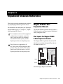
1
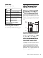
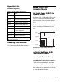
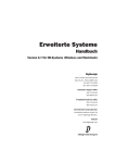
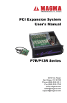
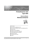
Pro Tools® Expanded Systems Guide Version 7.4 Legal Notices CE Compliance Statement: This guide is copyrighted ©2007 by Digidesign, a division of Avid Technology, Inc. (hereafter “Digidesign”), with all rights reserved. Under copyright laws, this guide may not be duplicated in whole or in part without the written consent of Digidesign. 003, 003 Rack, 96 I/O, 96i I/O, 192 Digital I/O, 192 I/O, 888|24 I/O, 882|20 I/O, 1622 I/O, 24-Bit ADAT Bridge I/O, AudioSuite, Avid, Avid DNA, Avid Mojo, Avid Unity, Avid Unity ISIS, Avid Unity MediaNetwork, Avid Xpress, AVoption, AVoption|V10, Beat Detective, Bruno, Command|8, Control|24, D-Command, D-Control, D-Fi, D-fx, D-Show, DAE, Digi 002, Digi 002 Rack, DigiBase, DigiDelivery, Digidesign, Digidesign Audio Engine, Digidesign Intelligent Noise Reduction, Digidesign TDM Bus, DigiDrive, DigiRack, DigiTest, DigiTranslator, DINR, DV Toolkit, EditPack, Impact, Interplay, M-Audio, MachineControl, Maxim, Mbox, MediaComposer, MIDI I/O, MIX, MultiShell, OMF, OMF Interchange, PRE, ProControl, Pro Tools M-Powered, Pro Tools, Pro Tools|HD, Pro Tools LE, QuickPunch, Reel Tape, Reso, Reverb One, ReVibe, RTAS, Smack!, SoundReplacer, Sound Designer II, Strike, Structure, SYNC HD, SYNC I/O, Synchronic, TL Space, Velvet, and X-Form are trademarks or registered trademarks of Digidesign and/or Avid Technology, Inc. All other trademarks are the property of their respective owners. Product features, specifications, system requirements, and availability are subject to change without notice. PN 9329-56820-00 REV A 07/07 Comments or suggestions regarding our documentation? email: [email protected] Warning This product contains chemicals, including lead, known to the State of California to cause cancer and birth defects or other reproductive harm. Wash hands after handling. Communications & Safety Regulation Information Compliance Statement The model Digidesign Expansion|HD complies with the following standards regulating interference and EMC: • FCC Part 15 Class A • EN55103 – 1, environment E4 • EN55103 – 2, environment E4 • AS/NZS 3548 Class A • CISPR 22 Class A • ICES-003 Class A Canadian Compliance Statement: This Class A digital apparatus complies with Canadian ICES003 Cet appareil numérique de la classe A est conforme à la norme NMB-003 du Canada. Digidesign is authorized to apply the CE (Conformité Europénne) mark on this compliant equipment thereby declaring conformity to EMC Directive 89/336/EEC and Low Voltage Directive 73/23/EEC. Australian Compliance: Radio and Television Interference This equipment has been tested and found to comply with the limits for a Class A digital device, pursuant to Part 15 of the FCC Rules. Communications Statement This equipment has been tested to comply with the limits for a Class A digital device. Changes or modifications to this product not authorized by Digidesign, Inc., could void the Certification and negate your authority to operate the product. This product was tested for CISPR compliance under conditions that included the use of peripheral devices and shielded cables and connectors between system components. Digidesign recommends the use of shielded cables and connectors between system components to reduce the possibility of causing interference to radios, television sets, and other electronic devices. Safety Statement This equipment has been tested to comply with USA and Canadian safety certification in accordance with the specifications of UL Standards: UL60065 7th /IEC 60065 7th and Canadian CAN/CSA C22.2 60065:03. Digidesign Inc., has been authorized to apply the appropriate UL & CUL mark on its compliant equipment. Warning Important Safety Instructions 1) Read these instructions. 2) Keep these instructions. 3) Heed all warnings. 4) Follow all instructions. 5) Do not use this apparatus near water. 6) Clean only with dry cloth. 7) Do not block any ventilation openings. Install in accordance with the manufacturer’s instructions. 8) Do not install near any heat sources such as radiators, heat registers, stoves, or other apparatus (including amplifiers) that produce heat. 9) Do not defeat the safety purpose of the polarized or grounding-type plug. A polarized plug has two blades with one wider than the other. A grounding type plug has two blades and a third grounding prong. The wide blade or the third prong are provided for your safety. If the provided plug does not fit into your outlet, consult an electrician for replacement of the obsolete outlet. 10) Protect the power cord from being walked on or pinched particularly at plugs, convenience receptacles, and the point where they exit from the apparatus. 11) Only use attachments/accessories specified by the manufacturer. 12) Unplug this apparatus during lightning storms or when unused for long periods of time. 13) Refer all servicing to qualified service personnel. Servicing is required when the apparatus has been damaged in any way, such as power-supply cord or plug is damaged, liquid has been spilled or objects have fallen into the apparatus, the apparatus has been exposed to rain or moisture, does not operate normally, or has been dropped. Do not attempt to service the equipment. There are no user-serviceable parts inside. Please refer all servicing to authorized Digidesign personnel. Any attempt to service the equipment will expose you to a risk of shock and will void the manufacturer’s warranty. SPECIAL WARNING REGARDING VENTILATION: Do not install the Digidesign Expansion|HD anywhere or in any way that blocks free air flow at any time around the back panel of the unit. contents Chapter 1. Introduction . . . . . . . . . . . . . . . . . . . . . . . . . . . . . . . . . . . . . . . . . . . . . . . . . . . . . . 1 Pro Tools Expanded Systems Without an Expansion Chassis . . . . . . . . . . . . . . . . . . . . . . . . . . 1 Pro Tools with an Expansion Chassis . . . . . . . . . . . . . . . . . . . . . . . . . . . . . . . . . . . . . . . . . . . 1 System Requirements and Compatibility . . . . . . . . . . . . . . . . . . . . . . . . . . . . . . . . . . . . . . . . 2 About www.digidesign.com . . . . . . . . . . . . . . . . . . . . . . . . . . . . . . . . . . . . . . . . . . . . . . . . . 2 Chapter 2. Expanded Pro Tools|HD Systems. . . . . . . . . . . . . . . . . . . . . . . . . . . . . . . . . . . . 3 Slot Order and Sample Rates . . . . . . . . . . . . . . . . . . . . . . . . . . . . . . . . . . . . . . . . . . . . . . . . 3 Adding Cards to Your System . . . . . . . . . . . . . . . . . . . . . . . . . . . . . . . . . . . . . . . . . . . . . . . . 4 Connecting Pro Tools|HD Cards . . . . . . . . . . . . . . . . . . . . . . . . . . . . . . . . . . . . . . . . . . . . . . 6 Connecting Audio Interfaces. . . . . . . . . . . . . . . . . . . . . . . . . . . . . . . . . . . . . . . . . . . . . . . . . 7 Powering Up An Expanded System . . . . . . . . . . . . . . . . . . . . . . . . . . . . . . . . . . . . . . . . . . . 12 Chapter 3. Digidesign Expansion|HD Chassis . . . . . . . . . . . . . . . . . . . . . . . . . . . . . . . . . . 15 System Requirements . . . . . . . . . . . . . . . . . . . . . . . . . . . . . . . . . . . . . . . . . . . . . . . . . . . . 15 Specifications . . . . . . . . . . . . . . . . . . . . . . . . . . . . . . . . . . . . . . . . . . . . . . . . . . . . . . . . . . 16 Installing the Digidesign Expansion|HD . . . . . . . . . . . . . . . . . . . . . . . . . . . . . . . . . . . . . . . . 17 Chapter 4. Expansion Chassis Reference . . . . . . . . . . . . . . . . . . . . . . . . . . . . . . . . . . . . . 21 Magma PE6R4 6-Slot Expansion Chassis . . . . . . . . . . . . . . . . . . . . . . . . . . . . . . . . . . . . . . . 21 Digidesign 64-Bit Expansion Chassis and Magma 64-Bit 7-Slot Expansion Chassis. . . . . . . . . . 23 Magma 32-Bit 7-Slot Expansion Chassis . . . . . . . . . . . . . . . . . . . . . . . . . . . . . . . . . . . . . . . 25 Pro Tools 13-Slot Expansion Chassis and Magma 13-Slot Expansion Chassis . . . . . . . . . . . . . 27 Pro Tools 7-Slot Expansion Chassis and SBS 7-Slot Expansion Chassis . . . . . . . . . . . . . . . . . . 29 Contents v vi Expanded Systems Guide chapter 1 Introduction You can expand your Pro Tools|HD® system by adding Pro Tools|HD cards, either directly in the computer or using an expansion chassis. Expanding your Pro Tools® system will provide increased track count, add to the amount of possible plug-in and mixer processing, and let you connect additional audio interfaces. For a list of system requirements for maximum track count, visit the Digidesign website (www.digidesign.com). Pro Tools Expanded Systems Without an Expansion Chassis It is possible to install as many as five Pro Tools cards in some computers. If you require more PCI card slots than your computer has available, you can use an expansion chassis. Pro Tools with an Expansion Chassis You can use a Digidesign 64-bit Expansion Chassis, a Digidesign Expansion|HD Chassis, or other Digidesign-qualified expansion chassis to increase the number of PCI card slots for your Pro Tools system. Expansion chassis will use only one PCI or PCIe card slot in your computer, and provide multiple PCI card slots in the chassis itself. Expansion chassis consist of a chassis that provides additional slots for your Pro Tools|HD cards, a host card (installed in your computer), and a cable that connects the host card to the controller card. Some chassis also include a controller card that is installed in the chassis, while some newer expansion chassis have a built-in controller that does not need to be installed. Check with the manufacturer of your chassis for details on the cable requirements for your equipment. Chapter 1: Introduction 1 System Requirements and Compatibility Pro Tools|HD systems can be used with a Digidesign-qualified Windows or Mac computer running Pro Tools HD software. For complete system requirements, visit the Digidesign website (www.digidesign.com). Compatibility Information Digidesign can only assure compatibility and provide support for hardware and software it has tested and approved. For a complete and current list of supported configurations of computers, expansion chassis, and hard drives, visit the Digidesign website (www.digidesign.com). PCI Compatibility Information for Windows For maximum track count with Pro Tools HD Accel (for PCI) systems, 64-bit PCI slots are are required. If using a CPU with mixed slot types, the 64-bit slots should be used first for the HD Core (for PCI) and subsequent HD Accel (for PCI) or HD Process cards, then use the 32-bit slots for any remaining HD Accel (for PCI) or HD Process cards. If you are using an expansion chassis, the 64-bit expansion chassis card should go in the first 64bit PCI slot. 2 Expanded Systems Guide About www.digidesign.com The Digidesign website (www.digidesign.com) is your best source for information to help you get the most out of your Pro Tools system. The following are just a few of the services and features available. Product Registration Register your purchase online. See the enclosed Digidesign Registration Information Card for instructions. Support and Downloads Contact Digidesign Technical Support or Customer Service; download software updates and the latest online manuals; find the latest system requirements; search the online Answerbase or join the worldwide Pro Tools community on the Digidesign User Conference. Training and Education Become a certified Pro Tools Operator or Expert; study on your own using courses available online, or find out how you can learn in a classroom setting at a certified Pro Tools Training Center. Products and Developers Learn about Digidesign products; download demo software; learn about our Development Partners and their plug-ins, applications, and hardware. News and Events Get the latest news from Digidesign or sign up for a Pro Tools demo. To learn more about these and other resources available from Digidesign, visit the Digidesign website (www.digidesign.com). chapter 2 Expanded Pro Tools|HD Systems This chapter provides the following information: • Slot order and sample rate information that applies to all expanded systems. • Instructions for installing an expanded system into slots in your computer (without an expansion chassis). • Instructions for how to connect Pro Tools|HD cards together using their FlexCables. These instructions apply to all systems. • Instructions for connecting audio interfaces. These instructions include DigiLink and Loop Sync connections, and apply to all systems. Computer Configuration (PCI) Card Type Order 1 HD Core (for PCI) card 2 HD Accel (for PCI) cards 3 HD Process (for PCI) cards 4 SCSI accelerator card Computer Configuration (PCIe) Card Type Order (Mac Only) 1 Accel Core (for PCIe) card 2 HD Accel (for PCIe) cards 3 SCSI HBA card Computer Configuration with Expansion Chassis Card Type Order Slot Order and Sample Rates To ensure maximum track counts and troublefree operations, it is important that cards are installed in the appropriate slot locations. Cards and Slot Order When installing cards in a computer or an expansion chassis, group cards according to type and install them in the following order, based on your Pro Tools system configuration: 1 Expansion chassis host card (PCI or PCIe) 2 SCSI HBA card Expansion Chassis Configuration Card Type Order 1 HD Core (for PCI) card 2 HD Accel (for PCI) cards 3 HD Process (for PCI) cards Chapter 2: Expanded Pro Tools|HD Systems 3 Sample Rate and Multiple Cards Pro Tools|HD supports sample rates of 44.1 kHz, 48 kHz, 88.2 kHz, 96 kHz, 176.4 kHz, and 192 kHz. However, due to the processing load required for 176.4 kHz and 192 kHz sessions, a maximum of four Pro Tools|HD cards can be used at these higher sample rates. The maximum number of Pro Tools|HD cards supported in a single system is seven. If your system includes more than four Pro Tools|HD cards, the fifth card (and any additional cards) will automatically be taken offline when Pro Tools sessions are set to 176.4 kHz or 192 kHz. You do not need to remove any cards; Pro Tools automatically deactivates the additional cards, and reactivates them when the sample rate is switched to 96 kHz or lower. Any audio interfaces connected to inactive cards will go offline and be unavailable. You should turn off power to offline interfaces connected to cards 5–7 (if any) and re-connect Loop Sync cables (bypassing the inactive interfaces) before starting Pro Tools. Achieving Maximum Voice Counts A compatible expansion chassis will provide maximum voice count for most sessions up to a 96 kHz sample rate, but has a reduced voice count at 176.4 and 192 kHz sample rates. Your results may vary depending on the specific model and capabilities of your computer, the sample rate of the current session, your operating system, and the specific model of your expansion chassis. For current information, visit the Digidesign website (www.digidesign.com). 4 Expanded Systems Guide Adding Cards to Your System To install Pro Tools cards: 1 Turn off your computer, expansion chassis, and any peripherals. To ensure proper grounding, connect the expansion chassis to a power source (such as a power strip or wall outlet), using the supplied AC cable. 2 Disconnect all cables attached to the com- puter (such as hard drives, displays, USB and FireWire connections) except for the power cable. 3 Open the computer case or expansion chassis. 4 Remove the metal access port cover behind the slot you want to use by removing the screw and sliding the cover out from the access port. Before handling any card, discharge static electricity from your clothes or body by touching a grounded metal surface, such as the power supply case inside your computer. 5 Install the HD Core (for PCI) or Accel Core (for PCIe) card in the lowest-numbered slot. • In a Windows computer, this will be the slot farthest from the graphics card. Always refer to your computer’s documentation to verify slot order. • In a Mac, slot order varies depending on the computer model. For details, see “Mac Reference” on page 5. • For systems with an expansion chassis, refer to Chapter 4, “Expansion Chassis Reference.” 6 Install HD Accel (for PCI or PCIe) cards in the next slots. PCIe slot 4 (hidden) Group cards of the same type together (for example, put all HD Accel cards next to each other). PCIe slot 3 PCIe slot 2 AGP slot 1 (video card) 7 Install HD Process cards (if any) in remaining slots. Make sure the first card is the core card for your system. Expansion cards (HD Accel or HD Process) cannot occupy the lowestnumbered slot. 8 Connect all Pro Tools|HD cards using Digide- Figure 1. Mac Pro sign TDM FlexCables (see “Connecting Pro Tools|HD Cards” on page 6). 9 If installing a SCSI HBA card in a system or ex- PCIe slot 4 pansion chassis that supports it, install it in the highest numbered remaining slot. PCIe slot 3 PCIe slot 2 Run DigiTest after making any changes to your hardware setup (such as adding or removing cards, audio interfaces, sync cables, and so on) to verify that your system is functioning properly. For DigiTest information, refer to the DigiTest Guide. AGP slot 1 (video card) 10 Secure each card in place with the slot access port screws you removed earlier. Mac Reference On a Mac, the lowest-numbered slot will be the slot closest to the graphics card, as shown in the following examples: Mac Pro and Power Mac G5 (PCI Express) The PCI Express-equipped Mac Pro and Power Mac G5 have three PCI Express (PCIe) slots (named slots 2, 3, and 4). The PCI Express slot numbers increase from bottom to top as you face the open computer case from the side. Install the Accel Core (for PCIe) card into PCI slot 2. Figure 2. Power Mac G5 (PCI Express equipped) To Install an HD card into Slot 4 on a Mac Pro: 1 Remove all SATA drive trays from the Mac Pro. 2 Place the rear of card into the access port. 3 Move the front of the card up and line it up with the PCIe slot and seat the card in the slot. 4 Replace the SATA drive trays. Chapter 2: Expanded Pro Tools|HD Systems 5 Power Mac G5 (PCI) The PCI-equipped Power Mac G5 has three PCI slots (named PCI slot 2, 3, and 4). PCI slot numbers increase from bottom to top as you face the open computer case from the side. Install the HD Core card into PCI slot 2. PCI slot 4 To connect Pro Tools|HD cards with the TDM FlexCable: 1 Shape the FlexCable before installing it on your Pro Tools|HD cards by grasping the cable with both hands with its printed side facing you and moving the Port B portion of the cable away from you and outwards, as shown below. Do not bend the cable more than you need to, as you may damage the traces in the cable. PCI slot 3 PCI slot 2 AGP slot 1 (video card) Preparing TDM FlexCable for installation 2 Turn the cable on its side, so that the connec- tors are facing downwards, and Port A is the higher side. Figure 3. Power Mac G5 Connecting Pro Tools|HD Cards Each Pro Tools|HD card has two ports along the top of the card, labelled Port A and Port B. The FlexCable has two connectors, also labeled Port A and Port B, to ensure proper connection. Data communication across cards is achieved by connecting Port B of the first card to Port A of the next card with a TDM FlexCable. The first FlexCable always goes from Port B on the core card to Port A on the first expansion card, as described in the following steps. Port A Port B Orienting the FlexCable 3 Slide the FlexCable into the notch of the second card, so that the Port B connector of the FlexCable can be aligned with Port B of the first card; and the Port A connector of the FlexCable can be aligned with Port A of the second card as shown below. Port A connector Port B connector HD Accel (or Process) HD Core Inserting TDM FlexCable 6 Expanded Systems Guide 4 Connect the Port A connector of the FlexCa- ble to Port A on the second card. Push down gently but firmly until the cable is fully connected to the card. Attach the other end of the FlexCable (labeled Port B) to Port B on the first card. HD Accel (or Process) card in PCI slot 3 Port Port BB Port AA Port Port Port BB Port AA Port HD Core card in PCI slot 2 Top view of TDM FlexCable connections for two Pro Tools|HD cards 5 Verify the connection. Make sure the FlexCa- ble ports seat flat against the sockets on the Pro Tools|HD cards, and are firmly attached. 6 For systems with more than two cards, con- nect each additional card to its preceding card. Use FlexCables to connect card pairs together, as described above, until all cards are connected. (Each expansion card is packaged with a FlexCable.) 7 Close the computer case. Connecting Audio Interfaces All Pro Tools|HD audio interfaces require DigiLink connections. When using multiple interfaces, you must also connect Loop Sync between all Pro Tools|HD audio interfaces. When using multiple Legacy I/Os (Pro Tools 24|MIX-series interfaces such as the 888|24 I/O and 882|20 I/O) you must connect Slave Clock to all Pro Tools|24|MIX-series audio interfaces. Recommended Ordering of Interfaces If your setup includes different types of audio interfaces, install them in the following order: 192 I/O or 192 Digital I/O Use as the primary audio interface. These interfaces provide the highest fidelity clock source for your system. If you have at least one 192 I/O or 192 Digital I/O in your Pro Tools system, it should be the primary audio interface and Loop Sync master. 96 I/O Use as the primary interface (if a 192 I/O or 192 Digital I/O is not installed), or as an expansion interface connected to the Expansion port of the primary interface. 96i I/O Use as the primary interface if no other Pro Tools|HD interfaces are installed, or as an expansion interface connected to the Expansion port of another Pro Tools|HD interface. Legacy I/Os See “Connecting Legacy Audio Interfaces” on page 10. Chapter 2: Expanded Pro Tools|HD Systems 7 DigiLink Connections The DigiLink cable connects Pro Tools|HD cards and audio interfaces. A single Digi-Link connector carries up to 32 channels of bidirectional audio information. These 32 channels are broken up into 2 groups of 16 channels: Group A = Channels 1–16, Group B = Channels 17–32. The maximum number of DigiLink cables supported on a single system is ten (for session sample rates up to 96 kHz) or eight (for session sample rates of 176.4 kHz or 192 kHz). Use the 12-foot DigiLink cable included with each Pro Tools|HD card to connect the card to a Digidesign audio interface. The primary audio interface, which functions as the Loop Sync master for other interfaces in the system, must be connected to the HD Core card. You can purchase optional DigiLink cables of differing lengths (25-foot, 50-foot, and 100-foot), depending on the needs of your studio configuration. Use the 18-inch DigiLink cable, included with each Pro Tools|HD audio interface, when connecting a secondary Pro Tools|HD audio interface to the Expansion port of another Pro Tools|HD audio interface. 8 Expanded Systems Guide HD Core or Accel Core card 18-inch DigiLink cable 12-foot DigiLink cable Loop Sync cables Figure 4. Two 96 I/Os, 32-channel HD Core or Accel Core card 18-inch DigiLink cable 12-foot DigiLink cable Loop Sync cables TDM FlexCable Loop Sync cables HD Accel card or HD Process card 12-foot DigiLink cable Figure 5. Three 96 I/Os, 48-channel Chapter 2: Expanded Pro Tools|HD Systems 9 To make DigiLink connections to Digidesign audio interfaces: 1 Connect the primary audio interface to the HD Core card with the provided 12-foot DigiLink cable. 2 Connect a secondary Pro Tools|HD audio in- terface to the Expansion port on the primary audio interface using the 18-inch DigiLink cable (included with the audio interface). See Figure 4 on page 9. – or – Connect a secondary Pro Tools|HD interface to the DigiLink on the next card (HD Accel or HD Process). 3 Connect additional Pro Tools|HD audio inter- faces to subsequent Pro Tools|HD audio interfaces or cards. See Figure 5 on page 9. 4 If connecting a Digidesign Legacy audio inter- face (such as the 888|24 I/O), refer to “Connecting Legacy Audio Interfaces” on page 10. Connecting Loop Sync To connect Loop Sync: 1 Connect the Loop Sync Out of the primary in- terface to the Loop Sync In of the second interface with the provided Loop Sync cables. When using a SYNC peripheral, the SYNC peripheral is considered the primary interface of the Loop Sync connection. For more information, refer to the SYNC peripheral guide. 2 Connect the Loop Sync Out of the second in- terface to the Loop Sync In of the next interface and so forth. 3 Connect the Loop Sync Out of the last inter- face to the Loop Sync In of the primary interface. 10 Expanded Systems Guide Connecting Legacy Audio Interfaces Each 192 I/O, 192 Digital I/O, and 96 I/O can support 16 channels of audio to and from Digidesign legacy audio interfaces, or Legacy I/Os. These include the 888|24 I/O, 882|20 I/O, 1622 I/O, 24-bit ADAT Bridge I/O, and the original ADAT Bridge I/O. The 888 I/O and 882 I/O interfaces are not supported with Pro Tools HD. (The 96i I/O does not provide a Legacy port.) The Legacy Peripheral port functions like the Expansion port. The Legacy port and the Expansion port both use Group B: Channels 17–32. you must choose between the Legacy port and the Expansion port in the Pro Tools Hardware Setup dialog. A single Legacy I/O can be connected to the Legacy Peripheral port using any Pro Tools MIX peripheral cable. Two Legacy I/Os can be connected to a single Legacy Peripheral port using a “Y” cable (16-channel Peripheral Cable Adapter). The maximum number of Legacy I/Os that can be connected to a Pro Tools|HD system is eight; requiring four Pro Tools|HD audio interfaces and four 16-channel Peripheral Cable Adapters. The Legacy port is not available in Pro Tools sessions at sample rates greater than 48 kHz. To connect Digidesign Legacy audio interfaces: 1 Connect one end of a Pro Tools|24 MIX pe- ripheral cable to the Legacy port on a 192 I/O, 192 Digital I/O, or 96 I/O. 2 Connect the other end of the cable to your MIX-compatible audio interface. 3 Connect the External Clock Out of the pri- mary interface to the Slave Clock In of the Legacy audio interface using a BNC cable. 4 If connecting two Legacy peripherals, connect the Slave Clock Out of the first Legacy peripheral to the Slave Clock In of the second Legacy peripheral. Do not connect the Slave Clock Out of the last Legacy peripheral to the clock input on any Pro Tools|HD interface. If using an 888|24 I/O, do not power on the 888|24 until you are ready to declare it in the Hardware Setup dialog, after launching Pro Tools. See the Pro Tools|HD Getting Started Guide for more information. Identifying Audio Interfaces If you have multiple audio interfaces of the same type connected to your system, you can confirm the identity of each interface. This ensures that you choose the appropriate interface in the Peripherals list when you define its inputs and outputs in the Hardware Setup dialog. To identify audio interfaces in your system: 1 Choose Setup > Hardware. 2 From the Peripherals list, select an audio interface connected to your system. 3 Click Main. 4 Select the Identify option, located in the lower left corner of the Hardware Setup dialog. This illuminates all the LEDs on the front panel of the selected audio interface. 5 Make a note of which interface in your studio setup corresponds to the identified interface. 6 Repeat the above steps for each additional audio interface in your setup. Number of I/O Channels in Expanded Systems You can add audio interfaces to your system to increase the number of available channels of hardware input and output. Hardware input and output includes digital and analog connections. Number of Channels of I/O Pro Tools|HD audio interfaces provide varying numbers of hardware input and output connectors and ports, a certain number of which can be utilized simultaneously. For specifications of Pro Tools|HD I/Os, refer to the Pro Tools|HD Getting Started Guide. The 96 I/O and standard 192 I/O are examples of symmetrical I/O, where there are the same number of input channels as output channels. For example, there are 8 analog inputs and 8 analog outputs. Though these I/Os provides many analog and digital connectors on their back panels, they support a total of 16 channels of simultaneous, discrete input and output. This means you can be listening to or recording as many as 16 channels of input while simultaneously monitoring or sending as many as 16 channels of output through a single I/O. The 192 I/O can be expanded by adding a 192 A/D or 192 D/A Expansion card to increase the number of analog inputs or analog outputs to 16. Expanded 192 I/O interfaces are an example of asymmetrical I/O when they have a different number of input channels or output channels. For example, when a 192 A/D card is installed on a standard 192 I/O, the I/O now has 16 analog inputs and 8 analog outputs. On Expanded 192 I/Os, the maximum number of simultaneous, discrete inputs and outputs is still 16. Chapter 2: Expanded Pro Tools|HD Systems 11 Because of the way in which 192 I/O interfaces can be expanded, the maximum number of channels of digital or analog I/O possible with an expanded Pro Tools|HD system depends on whether you use digital or analog connections, and whether you require a symmetrical or asymmetrical number of input and output channels, as explained in the following examples: Maximum I/O Configuration Examples Pro Tools|HD System with Ten Interfaces (Session Sample Rates Up to 96 kHz) Digital Up to 160 input and output channels (requires ten 192 Digital I/O interfaces) Analog Up to 120 simultaneous channels of input and output. Requires the following: • Five 192 I/O interfaces modified for 16 analog inputs and 8 analog outputs (requires adding an A/D card to each interface) • Five 192 I/O interfaces modified for 8 analog inputs and 16 analog outputs (requires adding a D/A card to each interface) Pro Tools|HD System with Eight Interfaces (Session Sample Rates Higher than 96 kHz) Digital Up to 128 channels of input and output (requires eight 192 Digital I/O interfaces) Analog Up to 96 simultaneous channels of input and output. Requires the following: • Four 192 I/O interfaces modified for 16 analog inputs and 8 analog outputs (requires adding an A/D card to each interface) • Four 192 I/O interfaces modified for 8 analog inputs and 16 analog outputs (requires a D/A card added each interface) 12 Expanded Systems Guide If you need more analog inputs and do not need all available analog outputs, use more A/D cards and fewer D/A cards. Conversely, to increase output capacity, use more D/A cards instead of A/D cards. Powering Up An Expanded System This section provides general information for powering up expanded systems. Make sure to have the expansion chassis cable connected to both the expansion chassis and the computer before powering up. If the cable becomes disconnected from the computer while the system is powered on, shut down power to the computer and then the expansion chassis before reconnecting. Before you connect your expansion chassis or install cards in it, make sure to turn off both the chassis and your computer. Starting Up and Shutting Down Your System Whenever you start your system, turn on all of your system components in a specific order. To start up your Pro Tools system: 1 Make sure all your equipment is off (including your computer). 2 Turn on the expansion chassis. 3 Turn on any external hard drives. Wait ap- proximately ten seconds for them to spin up to speed. 4 Turn on any MIDI interfaces and devices or any synchronization peripherals. 5 Lower the volume of all output devices, then turn on your Pro Tools audio interfaces. Wait at least fifteen seconds for the audio interfaces to initialize and the status LEDs to stop flashing. 6 Turn on your computer. To shut down your Pro Tools system: 1 Lower the volume of all output devices and monitors. 2 Shut down your computer. 3 Turn off Pro Tools audio interfaces. 4 Turn off any MIDI interfaces or devices. 5 Turn off external hard drives. 6 Turn off your expansion chassis. Chapter 2: Expanded Pro Tools|HD Systems 13 14 Expanded Systems Guide chapter 3 Digidesign Expansion|HD Chassis The Digidesign Expansion|HD is a six-slot PCI expansion chassis for Pro Tools|HD systems. Expansion|HD lets you install up to six Pro Tools|HD (for PCI) cards for additional plugin and mixer processing, and for connecting additional audio interfaces to the system. The Digidesign Expansion|HD package includes the following components: • Digidesign Expansion|HD chassis: 4U, 19-inch rackmount enclosure • Expansion|HD cable: 5-meter cable to connect the host card to the Expansion|HD chassis • AC power cable The following must be purchased separately from Digidesign: • PCI or PCIe Host Card: Dedicated card that is installed in the host computer and provides the connection to the chassis System Requirements The Digidesign Expansion|HD requires the following: • Digidesign-approved Windows or Mac dual-processor computer with PCI or PCIe slots • Pro Tools|HD or Pro Tools|HD Accel system • At least 1 GB RAM in the host computer • Pro Tools 7.1 software or higher For complete system requirements, visit the Digidesign website (www.digidesign.com). Compatibility Information Digidesign can only assure compatibility and provide support for hardware and software it has tested and approved. For a complete and current list of supported configurations of computers, expansion chassis, and hard drives, visit the Digidesign website (www.digidesign.com). Chapter 3: Digidesign Expansion|HD Chassis 15 RTAS Monitoring Latency with Expansion|HD Systems using the Digidesign Expansion|HD chassis will incur increased latency when monitoring the output of RTAS plug-ins, compared with systems where the Pro Tools|HD cards are installed in the host computer. This increase in RTAS monitoring latency is due to the hardware buffering needed for the Expansion|HD chassis. A Pro Tools Hardware Buffer setting of 256 samples on a Digidesign Expansion|HD system incurs the same RTAS monitoring latency as a hardware buffer setting of 512 samples on a system with the HD cards installed in the host computer. This increase in monitoring latency may be noticeable when playing RTAS virtual instrument plug-ins in real time. Specifications This section provides slot layout and technical specifications for the Digidesign Expansion|HD. The Digidesign Expansion|HD is for Pro Tools|HD (for PCI) cards only. It does not support Pro Tools|HD (for PCIe) cards, SCSI HBA cards, video cards, FireWire cards, or other special-purpose cards. Slot Layout The Digidesign Expansion|HD Chassis has slots that are numbered sequentially, right-to-left when viewed from the front (1–6). 6 5 4 3 2 1 RTAS monitoring latency can be reduced by decreasing the Hardware Buffer setting in Pro Tools. However, decreasing this setting may affect other areas of system performance. When Delay Compensation is active in Pro Tools, any delays incurred due to RTAS monitoring latency are correctly compensated during playback. To minimize RTAS real time monitoring latency when using the Digidesign Expansion|HD: 1 Launch Pro Tools. 2 Choose Setup > Playback Engine. 3 Set the HW Buffer to half of its previous set- ting (before you installed the Expansion|HD unit). For example, if the HW Buffer setting is 256 samples, set it to 128 samples. 16 Expanded Systems Guide Slot numbering for Digidesign Expansion|HD Hardware Specifications Host Card • PCI card or PCIe card Chassis Slots • Six PCI slots • Accepts the following Pro Tools|HD cards: • HD Core (for PCI) • HD Accel (for PCI) • HD Process (for PCI) Chassis Dimensions • Width: 19 in • Height: 4U (4 rack spaces) Expansion|HD Cable • Shielded Cat 6 cable Installing the Digidesign Expansion|HD Installation involves the following main steps, detailed in the sections that follow: • Installing the Expansion|HD host card in your computer • Connecting power to the Expansion|HD chassis (see “Connecting Power to the Expansion|HD” on page 18) • Installing Pro Tools|HD PCI cards into slots in the Digidesign Expansion|HD chassis, and connecting their FlexCables (see “Installing Pro Tools|HD Cards” on page 18) • Connecting the chassis to the host card in the computer (see “Connecting the Chassis to the Computer” on page 19) • Powering up your equipment (see “Starting Up Your System” on page 20) • RJ-45 connectors • Maximum cable length: 10 m Installing the Expansion|HD Host Card Ventilation Requirements Ventilation space is required at the front and rear of the unit. Do not block the front or back of the unit, and always be sure there is adequate air flow when mounting equipment into racks or studio furniture. To install the Expansion|HD host card: 1 Turn off your computer and any peripherals. 2 Open the computer case. For additional de- tails on installing a card in your computer, refer to its documentation. Before removing cards from their antistatic bags or handling any card, discharge any static electricity that may be on your clothes or body by touching a grounded metal surface (such as the power supply case inside your computer). Chapter 3: Digidesign Expansion|HD Chassis 17 3 Install the Expansion|HD host card in the lowest numbered available slot in your computer. Installing Pro Tools|HD Cards • In most Windows computers, this will be the slot farthest from the graphics card. To install Digidesign audio cards in the chassis: • In most Mac computers, this will be the slot closest to the graphics card. To ensure proper grounding, make sure the Expansion|HD is connected to a power source (such as a power strip or wall outlet), using the supplied AC cable. Refer to your computer’s documentation to verify slot order. Connecting Power to the Expansion|HD The AC Power connector on the rear panel of the Digidesign Expansion|HD accepts a standard AC power cable. The Expansion|HD is auto power-selecting (100V to 240V) and will automatically work with a standard modular cable to connect to AC power receptacles in any country. 1 Make sure the Expansion|HD is powered off. 2 Install the Pro Tools HD Core card in the first PCI slot of the expansion chassis. (This is the second slot from the right when the chassis is viewed from the front.) Do not use the video slot closest to the power supply. 6 5 4 3 2 1 Video slot Connecting AC Power and Standby Mode The Digidesign Expansion|HD requires an AC connection to power its PCI bus. The front panel Power switch toggles the Expansion|HD between standby and operating modes. To connect power to the Digidesign Expansion|HD: Connect the supplied AC cable to the AC connector on the back panel of the Expansion|HD. The power switch on the front panel flashes to indicate standby mode. Connection to a live AC power source automatically supplies power to the Expansion|HD chassis PCI bus, but does not power the unit on for operation. Slot numbering for Digidesign Expansion|HD 3 Install the remaining cards in successive card slots in the chassis, in the following order: • HD Accel • HD Process Only Pro Tools|HD (for PCI) cards can be installed in the chassis. PCIe cards are not supported. 18 Expanded Systems Guide 4 Connect all Pro Tools cards with TDM FlexCa- bles. See “Connecting Pro Tools|HD Cards” on page 6. After connecting cards with FlexCables, connect audio interfaces. See “Connecting Audio Interfaces” on page 7. After connecting audio interfaces, return here and complete the Digidesign Expansion|HD installation process. Connecting the Chassis to the Computer To connect the chassis to the computer: 1 Connect one end of the Expansion|HD cable to the Expansion|HD cable port on the chassis. Connect the cable securely (you should feel it click into place). Example The table shows one possible configuration of cards (and audio interface connections), using all slots in the Digidesign Expansion|HD. Chassis cards with multiple audio interfaces Slot Card Slot 1 HD Core (Interface #1 and #2) Slot 2 HD Accel (Interface #3 and #4) Expansion|HD back panel Slot 3 HD Accel (Interface #5 and #6) 2 Attach the other end of the cable to the port Slot 4 HD Accel (Interface #7 and #8) Slot 5* HD Accel (or Process) (Interface #9 and #10) on the host card in the computer. Connect the cable securely (you should feel it click into place). Slot 6* HD Accel (or Process) * Card only available at 44.1 kHz, 48 kHz, 88.2 kHz, and 96 kHz Expansion|HD cable port The only active port on the chassis is the Expansion|HD cable port. Do not connect video devices, iLoks, or other peripherals to any of the other ports on the Expansion|HD chassis. If your system includes both HD Accel and HD Process cards, always group like cards together in the order outlined above (keep all HD Accel cards next to each other, and any HD Process cards next to each other). For more information on using multiple audio interfaces, see “Number of I/O Channels in Expanded Systems” on page 11. Chapter 3: Digidesign Expansion|HD Chassis 19 Starting Up Your System Whenever you start your system, turn on all of your system components in a specific order. To start your Pro Tools system: 1 Make sure all your equipment is off (including your computer). On the front panel of the Digidesign Expansion|HD, the Power switch LED should be flashing to confirm that the unit is in Standby mode. 2 Press the Power switch on the front panel to turn on the Digidesign Expansion|HD. The Power switch LED remains lit when fully powered and ready for operation. power switch Location of the front panel Power switch 3 Turn on any external hard drives. Wait ap- proximately ten seconds for them to spin up to speed. 4 Turn on any MIDI interfaces and devices, or synchronization peripherals. 5 Lower the volume of all output devices, then turn on your Pro Tools audio interfaces. Wait at least fifteen seconds for the audio interfaces to initialize and the status LEDs to stop flashing. 6 Turn on your computer. 20 Expanded Systems Guide Launching and Configuring Pro Tools If you are installing a new Pro Tools system, refer to the instructions for launching and configuring Pro Tools in the Pro Tools|HD Getting Started Guide. chapter 4 Expansion Chassis Reference This chapter provides information for configuring Digidesign-qualified expansion chassis. For information on configuring the Digidesign Expansion|HD chassis, see Chapter 3, “Digidesign Expansion|HD Chassis.” For a complete and current list of supported configurations of computers, expansion chassis, and hard drives for maximum voices with Pro Tools systems, visit the Digidesign website (www.digidesign.com). Not all chassis are supported on all Pro Tools systems. Before purchasing an expansion chassis for your Pro Tools system, consult your Digidesign dealer or visit the Digidesign website (www.digidesign.com). Magma PE6R4 6-Slot Expansion Chassis The Magma PE6R4 expansion chassis includes a PCIe host card, 6-slot chassis, pair of Infiniband cables, and power cable. Slot Layout for Magma PE6R4 6-Slot Expansion Chassis The Magma PE6R4 expansion chassis has PCI slots that are numbered sequentially, right-toleft from the front (1–6). Slot 1 Slot 6 Slot numbering for Magma model PE6R4 Chapter 4: Expansion Chassis Reference 21 Configuring the Magma PE6R4 6-Slot Expansion Chassis Connecting the Expansion Chassis To install the PCIe host card in the computer: 1 Turn off the expansion chassis, your com- puter, and any peripherals. To ensure proper grounding, connect the expansion chassis to a power source (such as a power strip or wall outlet), using the supplied AC cable. 2 Open the computer case. For additional de- tails on installing a card in your computer, refer to its documentation. Before removing cards from their antistatic bags or handling any card, discharge any static electricity that may be on your clothes or body by touching a grounded metal surface (such as the power supply case inside your computer). 3 Install the host card in the lowest numbered PCIe slot in your computer. On a Windows PC, this will be the slot farthest from the graphics card. On a Mac, this will be the slot closest to the graphics card. Refer to your computer’s documentation to verify slot order. Connect the host card to the chassis: 2 Attach the other end of each cable to the cor- responding connector on the expansion chassis. Each cable should be attached to connectors with the same label (x1 or x3) on both ends. Refer to the expansion chassis guide for detailed instructions on connecting the Infiniband cables. 3 If using a SCSI HBA, do one of the following: • On Windows computers, install the SCSI HBA in the 64-bit slot closest to the graphics card. – or – • On Mac computers, install the SCSI HBA card in the highest numbered remaining slot. Installing the Digidesign Cards To install Digidesign audio cards in the chassis: 1 Install the Pro Tools|HD Core card in the first slot of the expansion chassis. 2 Install the remaining cards in successive PCI card slots in the chassis, in the following order: • HD Accel • HD Process Only Pro Tools|HD (for PCI) cards can be installed in the chassis. PCIe cards are not supported. 1 Attach one end of each Infiniband cable to the two connectors (labeled x1 and x3) on the host card. 22 Expanded Systems Guide 3 Connect all Pro Tools cards with TDM FlexCa- bles. See “Connecting Pro Tools|HD Cards” on page 6. Magma PE6R4 (Example Configuration) Chassis cards with multiple audio interfaces Slot Card Slot 1 HD Core (Interface #1 and #2) Slot 2 HD Accel (Interface #3 and #4) Slot 3 HD Accel (Interface #5 and #6) Slot 4 HD Accel (Interface #7 and #8) Slot 5* HD Accel (or Process) (Interface #9 and #10) Slot 6* HD Accel (or Process) * Card only available at 44.1 kHz, 48 kHz, 88.2 kHz, and 96 kHz Digidesign 64-Bit Expansion Chassis and Magma 64-Bit 7-Slot Expansion Chassis Slot Layout for Digidesign 64-Bit Expansion Chassis and Magma 64-Bit 7-Slot Expansion Chassis The Digidesign 64-Bit Expansion Chassis and Magma 64-bit, 33 MHz model P7R464-D1 and P7R464C1.5-D1 chassis have slots that are numbered sequentially, right-to-left from the front (1–7). Power Supply Connecting Audio Interfaces See “Connecting Audio Interfaces” on page 7. Slot 1 Slot 7 Slot numbering for Digidesign 64-Bit Expansion Chassis and Magma models P7R464-D1 and P7R464C1.5 Configuring the Digidesign 64-Bit Expansion Chassis or Magma 64-Bit 7-Slot Expansion Chassis Connecting the Expansion Chassis To install the chassis host card in the computer: 1 Turn off the expansion chassis, your com- puter, and any peripherals. To ensure proper grounding, connect the expansion chassis to a power source (such as a power strip or wall outlet), using the supplied AC cable. Chapter 4: Expansion Chassis Reference 23 2 Open the computer case. For additional de- tails on installing a card in your computer, refer to its documentation. Before removing cards from their antistatic bags or handling any card, discharge any static electricity that may be on your clothes or body by touching a grounded metal surface (such as the power supply case inside your computer). 3 Install the host card in the lowest numbered slot in your computer. On a Windows PC (such as an HP Workstation xw8000), this will be the slot furthest from the graphics card. On a Mac, this will be the slot closest to the graphics card. Refer to your computer’s documentation to verify slot order. 4 Attach a 1 meter or 1.5 meter expansion chassis cable to the host card. If necessary, refer to the chassis guide for specific instructions. 6-foot expansion chassis cables are not supported. 5 If using a SCSI HBA, do one of the following: • On Windows computers, install the SCSI HBA in the 64-bit slot closest to the graphics card. – or – • On Mac computers, install the SCSI HBA card in the highest numbered remaining slot. To install the chassis controller card (if one is required by your model of chassis): 1 Install the Magma Controller card in the Ex- pansion Slot of the expansion chassis. 2 Attach the other end of the expansion chassis cable to the controller card. If necessary, refer to the Magma guide for specific instructions. Installing the Digidesign Cards To install Digidesign audio cards in the chassis: 1 Install the Pro Tools|HD Core card in the first slot (numbered slot 4 in Magma models P7R-D1 and P7RQ-D1) of the expansion chassis. 2 Install the remaining cards in successive PCI card slots in the chassis, in the following order: • HD Accel • HD Process 3 Connect all Pro Tools cards with TDM FlexCa- bles. See “Connecting Pro Tools|HD Cards” on page 6. 24 Expanded Systems Guide Magma 64-bit 7-Slot (Example Configuration) Magma 32-Bit 7-Slot Expansion Chassis Chassis cards with multiple audio interfaces: Slot Card Exp. Slot Chassis Controller card (not all models) Slot 1 HD Core (Interface #1 and #2) Slot 2 HD Accel (interface #3 and #4) Slot 3 HD Accel (Interface #5 and #6) Slot 4 HD Accel (Interface #7 and #8) Slot 5* HD Accel (or HD Process) (Interface #9 and #10) Slot 6* HD Accel (or HD Process) Slot 7* HD Accel (or HD Process) * Card only available at 44.1 kHz, 48 kHz, 88.2 kHz, and 96 kHz Slot Layout Magma 32-Bit 7-Slot Expansion Chassis The Magma 32-bit, 33 MHz model P7R-D1 and P7RC1.5-D1 chassis have slots that are numbered sequentially, right-to-left from the front (4–10). This chassis does not support maximum track counts, and supports a maximum of 8 interfaces. Power Supply Expansion Controller Slot 4 Connecting Audio Interfaces See “Connecting Audio Interfaces” on page 7. Slot 10 Slot numbering for Magma models P7R-D1 and P7RC1.5-D1 Configuring the Magma 32-Bit 7-Slot Expansion Chassis Connecting the Expansion Chassis To install the chassis host card in the computer: 1 Turn off the expansion chassis, your com- puter, and any peripherals. To ensure proper grounding, connect the expansion chassis to a power source (such as a power strip or wall outlet), using the supplied AC cable. Chapter 4: Expansion Chassis Reference 25 2 Open the computer case. For additional de- Installing the Digidesign Cards tails on installing a card in your computer, refer to its documentation. To install Digidesign audio cards in the chassis: Before removing cards from their antistatic bags or handling any card, discharge any static electricity that may be on your clothes or body by touching a grounded metal surface (such as the power supply case inside your computer). 3 Install the host card in the lowest numbered slot in your computer. On a Windows PC (such as an HP Workstation xw8000 or Dell Precision Workstation 650), this will be the slot furthest from the graphics card. On a Mac, this will be the slot closest to the graphics card. Refer to your computer’s documentation to verify slot order. 1 Install the Pro Tools|HD Core card in the first slot (numbered slot 4 in Magma models P7R-D1 and P7RQ-D1) of the expansion chassis. 2 Install the remaining cards in successive PCI card slots in the chassis, in the following order: • HD Accel • HD Process 3 Connect all Pro Tools cards with TDM FlexCa- bles. See “Connecting Pro Tools|HD Cards” on page 6. Magma 32-bit 7-Slot (Example Configuration) Chassis cards with multiple audio interfaces 4 Attach a 1 meter or 1.5 meter expansion chas- Slot Card Exp. Slot Chassis Controller card 6-foot expansion chassis cables are not supported. Slot 1 HD Core (Interface #1 and #2) Slot 2 HD Accel (interface #3 and #4) 5 If using a SCSI HBA, install it in the highest Slot 3 HD Accel (Interface #5 and #6) Slot 4 HD Accel (Interface #7 and #8) To install the chassis controller card: Slot 5* HD Accel (or HD Process) 1 Install the Magma Controller card in the Ex- Slot 6* HD Accel (or HD Process) Slot 7* HD Accel (or HD Process) sis cable to the host card. If necessary, refer to the chassis guide for specific instructions. numbered remaining slot in your computer. pansion Slot of the expansion chassis. 2 Attach the other end of the expansion chassis cable to the controller card. If necessary, refer to the Magma guide for specific instructions. * Card only available at 44.1 kHz, 48 kHz, 88.2 kHz, and 96 kHz Connecting Audio Interfaces See “Connecting Audio Interfaces” on page 7. 26 Expanded Systems Guide Pro Tools 13-Slot Expansion Chassis and Magma 13-Slot Expansion Chassis (Mac Only) Configuring the Pro Tools 13-Slot Expansion Chassis or Magma 13-Slot Expansion Chassis Connecting the Expansion Chassis The 13-slot expansion chassis will support up to seven Pro Tools|HD cards. To install the chassis host card in the computer: Maximum track counts are not possible with this and other 32-bit chassis, and it supports a maximum of 8 audio interfaces. For track/voice count details, visit the Digidesign website (www.digidesign.com). puter, and any peripherals. To ensure proper grounding, connect the expansion chassis to a power source (such as a power strip or wall outlet), using the supplied AC cable. Slot Layout for Pro Tools 13-Slot Expansion Chassis and Magma 13-Slot Expansion Chassis The Digidesign Pro Tools 13-Slot Expansion Chassis and Magma model P13R-D1 and P13RC1.5-D1 chassis have slots that are numbered sequentially, right-to-left from the front, in two banks (4–9 and 4–10). Expansion Controller First Bank Slots 4–9 Second Bank Slots 4–10 Slot numbering for Pro Tools 13-Slot Expansion Chassis and Magma models P13R-D1 and P13RC1.5-D1 1 Turn off the expansion chassis, your com- 2 Open the computer case. For additional de- tails on installing a card in your computer, refer to its documentation. Before removing cards from their antistatic bags or handling any card, discharge any static electricity that may be on your clothes or body by touching a grounded metal surface (such as the power supply case inside your computer). 3 Install the host card in the lowest numbered slot in your computer. This will be the slot closest to the graphics card. Refer to your computer’s documentation to verify slot order. 4 Attach a 1 meter or 1.5 meter expansion chassis cable to the host card. If using Pro Tools 13-Slot Expansion Chassis or Magma 13-slot expansion chassis, make sure you attach the chassis cable to the host card and not your SCSI HBA. Both cards have a 68-pin VHDCI connector. 6-foot expansion chassis cables are not supported. Chapter 4: Expansion Chassis Reference 27 5 If using a SCSI HBA, install it in the highest numbered remaining slot in your computer. Install the chassis controller card in the chassis: Pro Tools 13-Slot Expansion Chassis (Example Configuration) Chassis cards with multiple audio interfaces 1 Install the Controller card in the Expansion Slot Card Slot of the expansion chassis. This is the slot nearest the power supply. Exp. Slot Chassis Controller card Bank 1/Slot 4 HD Core (Interface #1 and #2) Bank 1/Slot 5 HD Accel (interface #3 and #4) Bank 1/Slot 6 HD Accel (Interface #5 and #6) Bank 1/Slot 7 HD Accel (Interface #7 and #8) To install Digidesign audio cards in the chassis: Bank 1/Slot 8* HD Accel (or HD Process) 1 Install the Pro Tools Core card in slot 4 (the Bank 1/Slot 9* HD Accel (or HD Process) Bank 2/Slot 4* HD Accel (or HD Process) Bank 2/Slot 5 (empty) Bank 2/Slot 6 (empty) Bank 2/Slot 7 (empty) Bank 2/Slot 8 Available for non-bus master card Bank 2/Slot 9 Available for non-bus master card Bank 2/Slot 10 Available for non-bus master card 2 Attach the other end of the expansion chassis cable to the controller card. Installing the Digidesign Cards first available slot) of the expansion chassis. 2 Install the remaining cards in successive PCI card slots in the chassis, in the following order: • HD Accel • HD Process 3 Connect all Pro Tools cards with TDM FlexCa- bles. See “Connecting Pro Tools|HD Cards” on page 6. * Card only available at 44.1 kHz, 48 kHz, 88.2 kHz, and 96 kHz Connecting Audio Interfaces See “Connecting Audio Interfaces” on page 7. 28 Expanded Systems Guide Pro Tools 7-Slot Expansion Chassis and SBS 7-Slot Expansion Chassis (Mac Only) Pro Tools 7-Slot Expansion Chassis The Digidesign Pro Tools 7-Slot Expansion Chassis is identical to the SBS 32-bit model DD007-R. For compatibility and configuration details, refer to the information that pertains to that model. Slot Layout for Pro Tools 7-Slot Expansion Chassis and SBS 7-Slot Expansion Chassis The Pro Tools 7-Slot Expansion Chassis and SBS model DD007-R chassis have slots that are numbered sequentially (1–7), left-to-right, from the front. These chassis do not have a Backplane Controller slot. Instead, they have a built-in chassis controller with a connector on the back of the expansion chassis. Maximum track counts are not possible with these chassis, and they support a maximum of 8 audio interfaces. For track/voice count details, visit the Digidesign website (www.digidesign.com). The Pro Tools 7-Slot Expansion Chassis and SBS model DD007-R are supported on Mac OS X. Slot 7 Slot 1 SBS Technologies was previously called “Bit 3.” Slot numbering for Pro Tools 7-Slot Expansion Chassis and SBS 7-Slot Expansion Chassis Configuring the Pro Tools 7-Slot Expansion Chassis or SBS Expansion Chassis Connecting the Expansion Chassis To install the chassis host card in the computer: 1 Turn off the expansion chassis, your com- puter, and any peripherals. To ensure proper grounding, connect the expansion chassis to a power source (such as a power strip or wall outlet), using the supplied AC cable. Chapter 4: Expansion Chassis Reference 29 2 Open the computer case. For additional de- 2 Install the remaining cards in successive PCI tails on installing a card in your computer, refer to its documentation. card slots in the chassis, in the following order: Before removing cards from their antistatic bags or handling any card, discharge any static electricity that may be on your clothes or body by touching a grounded metal surface (such as the power supply case inside your computer). • HD Accel • HD Process 3 Connect all Pro Tools cards with TDM FlexCa- bles. See “Connecting Pro Tools|HD Cards” on page 6. Pro Tools 7-Slot Expansion Chassis 3 Install the host card in the lowest numbered (Example Configuration) slot in your computer. This will be the slot closest to the graphics card. Chassis cards with multiple audio interfaces Refer to your computer’s documentation to verify slot order. 4 Attach a 1 meter or 1.5 meter expansion chas- Slot Card Slot 1 HD Core (Interface #1 and #2) Slot 2 HD Accel (or HD Process) (interface #3 and #4) Slot 3 HD Accel (or HD Process) (interface #5 and #6) Slot 4 HD Accel (or HD Process) (interface #7 and #8) Slot 5* HD Accel (or HD Process) Slot 6* HD Accel (or HD Process) Slot 7* HD Accel (or HD Process) sis cable to the host card. 6-foot expansion chassis cables are not supported. 5 If using a SCSI HBA, install it in the highest numbered remaining slot in your computer. To install the chassis controller card in the chassis: 1 Attach the chassis cable to the connector on the back of the expansion chassis. * Card only available at 44.1 kHz, 48 kHz, 88.2 kHz, and 96 kHz 2 Attach the other end of the expansion chassis cable to the controller card. Connecting Audio Interfaces See “Connecting Audio Interfaces” on page 7. Installing the Digidesign Cards To install Digidesign audio cards in the chassis: 1 Install the Pro Tools Core card (clock master with primary audio interface) in slot 1 of the expansion chassis. 30 Expanded Systems Guide www.digidesign.com DIGIDESIGN 2001 Junipero Serra Boulevard Daly City, CA 94014-3886 USA Tel: 650.731.6300 Fax: 650.731.6399 TECHNICAL SUPPORT (USA) Tel: 650.731.6100 Fax: 650.731.6384 PRODUCT INFORMATION (USA) Tel: 800.333.2137 INTERNATIONAL OFFICES Visit the Digidesign website for contact information