1
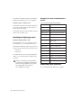
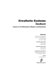
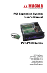
Expanded Systems
Guide
Version 6.7 for HD Systems on Windows or Macintosh
Digidesign
2001 Junipero Serra Boulevard
Daly City, CA 94014-3886 USA
tel: 650·731·6300
fax: 650·731·6399
Technical Support (USA)
650·731·6100
650·856·4275
Product Information (USA)
650·731·6102
800·333·2137
International Offices
Visit the Digidesign Web site
for contact information
Web Site
www.digidesign.com
Copyright
This guide is copyrighted ©2004 by Digidesign, a division of
Avid Technology, Inc. (hereafter “Digidesign”), with all rights
reserved. Under copyright laws, this guide may not be
duplicated in whole or in part without the written consent of
Digidesign.
DIGIDESIGN, AVID and PRO TOOLS are trademarks or
registered trademarks of Digidesign and/or Avid Technology,
Inc. All other trademarks are the property of their respective
owners.
Product features, specifications, system requirements, and
availability are subject to change without notice.
PN 932014021-00 REV A 09/04
contents
Chapter 1. Introduction . . . . . . . . . . . . . . . . . . . . . . . . . . . . . . . . . . . . . . . . . . . . . . . . . . . . . . 1
Pro Tools Expanded Systems Without an Expansion Chassis . . . . . . . . . . . . . . . . . . . . . . . . . . 1
Pro Tools with an Expansion Chassis . . . . . . . . . . . . . . . . . . . . . . . . . . . . . . . . . . . . . . . . . . . 1
Compatibility Information. . . . . . . . . . . . . . . . . . . . . . . . . . . . . . . . . . . . . . . . . . . . . . . . . . . 2
About www.digidesign.com . . . . . . . . . . . . . . . . . . . . . . . . . . . . . . . . . . . . . . . . . . . . . . . . . 2
Chapter 2. Expanded Pro Tools|HD Systems. . . . . . . . . . . . . . . . . . . . . . . . . . . . . . . . . . . . 3
Adding Cards to Your System . . . . . . . . . . . . . . . . . . . . . . . . . . . . . . . . . . . . . . . . . . . . . . . . 4
Connecting Pro Tools|HD Cards . . . . . . . . . . . . . . . . . . . . . . . . . . . . . . . . . . . . . . . . . . . . . . 6
Connecting Audio Interfaces . . . . . . . . . . . . . . . . . . . . . . . . . . . . . . . . . . . . . . . . . . . . . . . . . 9
Chapter 3. Expansion Chassis . . . . . . . . . . . . . . . . . . . . . . . . . . . . . . . . . . . . . . . . . . . . . . . 13
Digidesign 64-Bit Expansion Chassis and Magma 64-Bit 7-Slot Expansion Chassis . . . . . . . . . . 14
Magma 32-Bit 7-Slot Expansion Chassis . . . . . . . . . . . . . . . . . . . . . . . . . . . . . . . . . . . . . . . 15
Pro Tools 13-Slot Expansion Chassis and Magma 13-Slot Expansion Chassis . . . . . . . . . . . . . 17
Pro Tools 7-Slot Expansion Chassis and SBS 7-Slot Expansion Chassis . . . . . . . . . . . . . . . . . . 19
Contents
iii
iv
Expanded Systems Guide
chapter 1
Introduction
You can expand your Pro Tools TDM system by
adding Pro Tools TDM cards to your computer,
either directly in the computer or using an expansion chassis. Expanding your Pro Tools system will provide an increased track count, add
to the amount of possible plug-in and mixer
processing, and let you connect additional audio interfaces.
For Pro Tools|24 MIX systems, refer to the
previous version of this guide, published
with Pro Tools 6.1 software. This guide is
available online, with other Pro Tools 6.1
documentation, at the Digidesign Web site
(www.digidesign.com).
Pro Tools Expanded Systems
Without an Expansion Chassis
Pro Tools|HD-series systems include an HD Core
card, and can include one or more HD Accel or
HD Process cards.
It is possible to install as many as five Pro Tools
cards in some computers. If you require more
PCI card slots than your computer has available,
you can use an expansion chassis.
Pro Tools with an Expansion
Chassis
You can use a Digidesign or Digidesign-qualified
expansion chassis to increase the number of PCI
card slots for your Pro Tools system. Expansion
chassis will use only one PCI card slot in your
computer and provide up to 13 additional PCI
card slots in the chassis itself.
Expansion chassis consist of a chassis (providing
additional PCI slots for your Digidesign cards), a
host card (installed in your computer), a controller card (installed in the chassis), and an expansion chassis cable that connects the host
card to the controller card. Some newer expansion chassis have a built-in controller card that
does not need to be installed.
6-foot expansion chassis cables are not supported.
7-slot chassis support up to seven Pro Tools|HDseries cards. Refer to the Digidesign Web site for
the latest compatibility information
(www.digidesign.com/compato).
For PCI, hard drive, and other requirements
for maximum track count, see the compatibility information on the Digidesign Web
site (www.digidesign.com/compato).
Chapter 1: Introduction
1
13-slot expansion chassis support up to seven
Pro Tools|HD-series cards.
See Chapter 3, “Expansion Chassis” for
more information about card slot order and
installing Pro Tools cards in an expansion
chassis.
Powering Up Expansion Chassis
Make sure to have the expansion chassis cable
connected to both the expansion chassis and
the computer before powering up. If the cable
becomes disconnected from the computer while
the system is powered on, shut down power to
the computer and then the expansion chassis
before reconnecting.
Before you connect your expansion chassis,
or install cards in it, make sure to turn off
both the chassis and your computer.
When powering up, turn on the expansion
chassis before the computer, and turn it off after
powering down the computer.
Compatibility Information
For maximum track count with
Pro Tools|HD Accel systems, 64-bit PCI is required. If using a CPU with mixed slot types, the
64-bit slots should be used first for the HD Core
and subsequent HD Accel or HD Process cards,
then use the 32-bit slots for any remaining HD
Accel or HD Process cards. If used, the 64-bit expansion chassis card should go in the first 64-bit
PCI slot.
Digidesign can only assure compatibility and
provide support for hardware and software it
has tested and approved.
2
Expanded Systems Guide
For a complete and current list of supported
configurations of computers, expansion chassis,
and hard drives, visit the Digidesign Web site
(www.digidesign.com/compato).
About www.digidesign.com
The Digidesign Web site (www.digidesign.com)
is your best online source for information to
help you get the most out of your Pro Tools system. The following are just a few of the services
and features available.
Support Contact Digidesign Technical Support
or Customer Service; download software updates and the latest online manuals; browse the
Compatibility documents for system requirements; search the online Answerbase or join the
worldwide Pro Tools community on the Digidesign User Conference.
Training and Education Study on your own using
courses available online or find out how you can
learn in a classroom setting at a certified
Pro Tools training center.
Products and Developers Learn about Digidesign
products; download demo software or learn
about our Development Partners and their plugins, applications, and hardware.
News and Events Get the latest news from Digidesign or sign up for a Pro Tools demo.
To learn more about these and other resources
available from Digidesign, visit the Digidesign
Web site (www.digidesign.com).
chapter 2
Expanded Pro Tools|HD Systems
To ensure maximum track counts and troublefree operations, it is important that PCI cards are
installed in the appropriate slot locations.
For maximum track count with
Pro Tools|HD Accel systems, 64-bit PCI is
required. If using a CPU with mixed slot
types, the 64-bit slots should be used first
for the HD Core and subsequent HD Accel
or HD Process cards, then use the 32-bit
slots for any remaining HD Accel or HD
Process cards. If used, the 64-bit expansion
chassis card should go in the first 64-bit PCI
slot.
For a complete and current list of supported
configurations of computers, expansion
chassis, and hard drives, visit the compatibility page of the Digidesign Web site
(www.digidesign.com/compato).
Cards and Slot Order
When installing ‘cards’ in a computer or an expansion chassis, group cards according to type
and install them in the following order, based
on your Pro Tools system configuration:
Computer Configuration
1 HD Core card
2 HD Accel cards
4 SCSI accelerator cards
Computer Configuration with Expansion
Chassis
1 Expansion chassis host card
2 SCSI accelerator card
Expansion Chassis Configuration
1 HD Core card
2 HD Accel cards
3 HD Process cards
Sample Rate and Multiple Cards
Pro Tools|HD supports sample rates of 44.1 kHz,
48 kHz, 88.2 kHz, 96 kHz, 176.4 kHz, and
192 kHz. However, due to the processing load
required for 176.4 kHz and 192 kHz sessions, a
maximum of four HD-series cards can be used at
these higher sample rates.
If your system includes more than four
Pro Tools|HD-series cards, the fifth card (and
any additional cards) will automatically be
taken offline when Pro Tools sessions are set to
176.4 kHz or 192 kHz. You do not need to remove any cards or cables; Pro Tools automatically deactivates the additional cards, and reactivates them when the sample rate is switched to
96 kHz or lower.
3 HD Process cards
Chapter 2: Expanded Pro Tools|HD Systems
3
Any audio interfaces connected to inactive cards
will go offline.
Adding Cards to Your System
The maximum number of HD-series cards supported in a single system is seven. However,
there may be further restrictions depending on
sample rate, your operating system, and the specific model of your expansion chassis. For the
most current information, visit the Digidesign
Web site (www.digidesign.com/compato).
To install Pro Tools cards:
1 Turn off your computer, expansion chassis,
8 Install the HD Core card in the lowest num-
bered slot.
On a Windows PC, this will be the slot furthest
from the graphics card.
Refer to your computer’s documentation to
verify slot order.
On a Macintosh, this will be the slot closest to
the graphics card, as shown in the following examples:
Power Mac G5 The Power Mac G5 has three PCI
slots (named PCI slot 2, 3, and 4). PCI slot numbers increase from bottom to top as you face the
open computer case from the front. Install the
HD Core card into PCI slot 2.
and any peripherals. To ensure proper grounding, connect the expansion chassis to a power
source (such as a power strip or wall outlet), using the supplied AC cable.
PCI slot 4
PCI slot 3
2 Wait 5–10 minutes to allow the computer’s in-
ternal components to cool down to avoid burning yourself.
PCI slot 2
AGP slot 1
(video card)
3 Disconnect all cables attached to the computer (such as hard drives, displays, USB and
FireWire connections) except for the power cable.
4 To prevent damaging sensitive electronics,
discharge any static electricity that may be on
your clothes or body by touching a grounded
metal surface, such as the metal PCI access covers on the back of the computer.
5 Disconnect the power cord from the computer.
Figure 1. Power Mac G5
Power Macintosh “Mirrored Door” G4 The Power
Macintosh “Mirrored Door” G4 has reflective
drive bay doors and four holes across the front.
Its PCI slot numbers increase from left to right as
you face the open computer case from the front.
6 Open the computer case or expansion chassis.
7 Remove the metal access port cover behind
the expansion slot you want to use by removing
the screw and sliding the cover out from the access port. Keep the screws in a safe place.
4
Expanded Systems Guide
Note that the PCI slot numbering in the newer
“Mirrored Door” G4 computer runs in the opposite direction of previous G4 models.
Be very careful when opening or closing the
case of a “Mirrored Door” G4 computer.
Any PCI cards installed in the higher-numbered slots may be damaged if they touch
the top of the computer case.
PCI slot 4
PCI slot 3
PCI slot 2
PCI slot 1 (video card)
AGP slot 1 (video card)
PCI slot 2
PCI slot 3
PCI slot 4
PCI slot 5
Power Macintosh Single Processor G4
9 Install HD Accel cards (if any) in the next
slots.
Group similar cards together (for example,
put all HD Accel cards next to each other).
Power Macintosh “Mirrored Door” Dual Processor G4
Power Macintosh “QuickSilver” G4 The Power
Macintosh “QuickSilver” and earlier G4 models
have a single speaker grille or hole on the front.
Their PCI slot numbers increase from right to left
as you face the open computer case from the
front.
PCI slot 4
PCI slot 3
PCI slot 2
AGP slot 1 (video card)
10 Install HD Process cards (if any) in remaining
slots.
Make sure the first card is a Core card.
HD Accel and HD Process cards cannot occupy the lowest-numbered slot.
11 Connect all Pro Tools|HD cards using Digidesign TDM FlexCables (see “Digidesign TDM
FlexCable” on page 6).
12 If installing a SCSI HBA card, install it in the
highest numbered remaining slot.
Run DigiTest after making any changes to
your hardware setup (such as adding or removing cards, audio interfaces, sync cables,
and so on) to verify that your system is
functioning properly. For DigiTest information, refer to your Getting Started Guide.
13 Secure each card in place with the slot access
Power Macintosh “QuickSilver” Dual Processor G4
port screws you removed earlier.
Chapter 2: Expanded Pro Tools|HD Systems
5
Connecting Pro Tools|HD
Cards
Digidesign TDM FlexCable
Digidesign TDM FlexCable cables connect one
Pro Tools|HD card to another. You will need an
additional TDM FlexCable for each additional
card.
2 Slide the FlexCable into the notch of the first
card, so that the Port B connector of the FlexCable can be aligned with Port B of the first card;
and the Port A connector of the FlexCable can
be aligned with Port A of the second card, as
shown below.
HD Accel card
(or HD Process card)
Each HD card has two ports along the top of the
card, labelled Port A and Port B. The FlexCable
has two connectors, also labeled Port A and Port
B, to ensure proper connection.
When installing multiple HD cards, data communication across HD cards is achieved by using the TDM FlexCable to connect Port B of the
first card to Port A of the next card.
To connect HD cards with the TDM FlexCable on a
Windows PC or Power Macintosh “Mirrored Door”
G4
1 Shape the FlexCable before installing it on
your HD cards by grasping the cable with both
hands and moving the Port B portion of the cable straight towards you and inwards, as shown
below. Do not bend the cable more than you
need to, as you may damage the traces in the cable.
Inserting TDM FlexCable
3 Connect the Port A connector of the Flex-
Cable to Port A on the second card. Push down
gently but firmly until the cable is fully connected to the card. Attach the other end of the
FlexCable (labeled Port B) to Port B on the first
card.
HD Accel card
(or HD Process
card)
HD Core card
Top view of two HD cards connected with TDM FlexCable
4 Verify the connection, as shown below (orientation may be different depending on your type
of CPU or chassis).
Preparing TDM FlexCable for installation
The first FlexCable always go from Port B
on the HD card to Port A on the Accel or
Process card.
Side view of two HD cards connected with TDM
FlexCable
6
Expanded Systems Guide
5 For systems with more than two cards, con-
3 Slide the FlexCable into the notch of the sec-
nect each additional card to its preceding card.
Use FlexCables to connect card pairs together, as
described above, until all cards are connected.
(Each HD Accel card is packaged with a FlexCable.)
ond card, so that the Port B connector of the
FlexCable can be aligned with Port B of the first
card; and the Port A connector of the FlexCable
can be aligned with Port A of the second card as
shown below.
6 Close the computer case.
7 Proceed to “Connecting Audio Interfaces” on
Port A connector
Port B
connector
HD Accel
(or Process)
page 9.
To connect HD cards with the TDM FlexCable on
the Power Mac G5:
HD Core
1 Shape the FlexCable before installing it on
your HD cards by grasping the cable with both
hands with its printed side facing you and moving the Port B portion of the cable away from
you and outwards, as shown below. Do not
bend the cable more than you need to, as you
may damage the traces in the cable.
Inserting TDM FlexCable
4 Connect the Port A connector of the Flex-
Cable to Port A on the second card. Push down
gently but firmly until the cable is fully connected to the card. Attach the other end of the
FlexCable (labeled Port B) to Port B on the first
card.
HD Accel (or Process) card in PCI slot 3
Port
Port
BB
Port AA
Port
PortB B
Port
Port AA
Port
Preparing TDM FlexCable for installation
2 Turn the cable on its side, so that the connec-
tors are facing downwards, and Port A is the
higher side.
HD Core card in PCI slot 2
Top view of TDM FlexCable connections for two HD
cards
5 Verify the connection. Make sure the FlexCable ports seat flat against the sockets on the
HD cards, and are firmly attached.
Port A
6 For systems with more than two cards, conPort B
Orienting the FlexCable
nect each additional card to its preceding card.
Use FlexCables to connect card pairs together, as
described above, until all cards are connected.
Each HD Accel or HD Process card is packaged
with a FlexCable.
7 Close the computer case.
Chapter 2: Expanded Pro Tools|HD Systems
7
8 Proceed to “Connecting Audio Interfaces” on
page 9.
To connect HD cards with the TDM FlexCable on
Power Macintosh “QuickSilver” and earlier G4
computers:
1 Shape the FlexCable before installing it on
your HD cards by grasping the cable with both
hands and moving the Port A portion of the cable straight towards you and inwards, as shown
below. Do not bend the cable more than you
need to, as you may damage the traces in the cable.
3 Connect the Port A connector of the Flex-
Cable to Port A on the second card. Push down
gently but firmly until the cable is fully connected to the card. Next, attach the other end of
the FlexCable (labeled Port B) to Port B on the
first card.
PORT A
PORT B
PORT A
PORT B
Top view of two HD cards connected with TDM FlexCable
4 Verify the connection, as shown below.
PORT B
PORT A
PORT A
PORT B
PORT A
PORT
PO
RTAA
PO
PORT
RT B
B
PORT B
PORT A
PORT B
Preparing TDM FlexCable for installation
2 Slide the FlexCable into the notch of the second card, so that the Port B connector of the
FlexCable can be aligned with Port B of the first
card; and the Port A connector of the FlexCable
can be aligned with Port A of the second card, as
shown below.
PORT A
PORT A
5 For systems with more than two cards, con-
nect each additional card to its preceding card.
Use FlexCables to connect card pairs together, as
described above, until all cards are connected.
(Each HD Accel card is packaged with a FlexCable.)
PORT B
PORT A
Side view of two HD cards connected with TDM
FlexCable
PORT B
PORT B
PORT A
PORT B
6 Close the computer case.
7 Proceed to “Connecting Audio Interfaces” on
page 9.
Inserting TDM FlexCable
8
Expanded Systems Guide
For more information about installing
Pro Tools|HD-series cards see the “Getting
Started with HD Guide.”
Connecting Audio Interfaces
All HD-series audio interfaces require DigiLink
connections. When using multiple interfaces,
you must also connect Loop Sync between all
HD-series audio interfaces. When using multiple Legacy interfaces (MIX-series I/O such as the
888|24 I/O and 882|20 I/O) you must connect
Slave Clock to all MIX-series audio interfaces.
Recommended Ordering of Interfaces
If your setup includes different types of audio
interfaces, install them in the following order:
192 I/O or 192 Digital I/O Use as the primary audio interface. These interfaces provide the highest fidelity clock source for your system.
If you have at least one 192 I/O or
192 Digital I/O in your Pro Tools system, it
should be the primary audio interface and
Loop Sync master.
96 I/O Use as the primary interface (if a 192 I/O
or 192 Digital I/O is not installed), or as an expansion interface connected to the Expansion
port of the primary interface.
96i I/O Use as the primary interface if no other
HD-series interfaces are installed, or as an expansion interface connected to the Expansion
port of another HD-series interface.
DigiLink
The DigiLink cable connects HD cards and audio interfaces. A single Digi-Link connector carries up to 32 channels of bidirectional audio information. These 32 channels are broken up
into 2 groups of 16 channels: Group A = Channels 1–16, Group B = Channels 17–32.
The maximum number of DigiLink cables supported on a single system is eight. This allows up
to 128 channels of I/O with eight HD-series audio interfaces: four connected directly to an HD
card and the remaining four connected to the
expansion ports of the first four.
◆ Use the 12-foot DigiLink cable included with
each Pro Tools|HD card to connect the card to a
Digidesign audio interface. The primary audio
interface, which functions as the Loop Sync
master for other interfaces in the system, must
be connected to the HD Core card. You can purchase optional DigiLink cables of differing
lengths (25-foot, 50-foot, and 100-foot), depending on the needs of your studio configuration.
◆ Use the 18-inch DigiLink cable, included with
each HD-series audio interface, when connecting a secondary HD-series audio interface to the
Expansion port of another HD-series audio interface.
Legacy Peripherals See “Using Legacy Audio Interfaces” on page 12.
Chapter 2: Expanded Pro Tools|HD Systems
9
To make DigiLink connections to Digidesign audio
interfaces:
Loop Sync
1 Connect the primary audio interface to the
HD Core card with the provided 12-foot DigiLink cable.
To connect Loop Sync:
2 Connect a secondary HD-series audio interface to the Expansion port on the primary audio
interface using the 18-inch DigiLink cable (included with the audio interface). See Figure 2 on
page 11.
1 Connect the Loop Sync Out of the primary in-
terface to the Loop Sync In of the second interface with the provided Loop Sync cables.
When using a Sync I/O, the Sync I/O is considered the primary interface of the Loop
Sync connection. For more information, refer to the Sync I/O Guide.
– or –
• Connect a secondary HD-series interface to
the DigiLink on the next card (HD Accel or
HD Process).
3 Connect additional HD-series audio interfaces
to subsequent Pro Tools|HD audio interfaces or
cards. See Figure 3 on page 11.
4 If connecting a Digidesign Legacy audio inter-
face (such as the 888|24 I/O), refer to “Using
Legacy Audio Interfaces” on page 12.
10
Expanded Systems Guide
2 Connect the Loop Sync Out of the second interface to the Loop Sync In of the next interface
and so forth.
3 Connect the Loop Sync Out of the last inter-
face to the Loop Sync In of the primary interface.
HD Core
18-inch
DigiLink
cable
12-foot DigiLink cable
Loop Sync cables
Figure 2. Two 96 I/Os, 32-channel
HD Core
18-inch
DigiLink
cable
12-foot DigiLink cable
Loop Sync cables
TDM FlexCable
Loop Sync cables
HD Accel
or HD Process
12-foot DigiLink cable
Figure 3. Three 96 I/Os, 48-channel
Chapter 2: Expanded Pro Tools|HD Systems
11
Using Legacy Audio Interfaces
Each 192 I/O, 192 Digital I/O, and 96 I/O can
support 16 channels of audio to and from Digidesign legacy audio interfaces, or Legacy I/Os.
These include the 888|24 I/O, 882|20 I/O,
1622 I/O, 24-bit ADAT Bridge I/O, and the original ADAT Bridge I/O. The 888 I/O and 882 I/O
interfaces are not supported with Pro Tools|HD.
(The 96i I/O does not provide a Legacy port.)
The Legacy Peripheral port functions like the
Expansion port.
The Legacy port and the Expansion port
both use Group B: Channels 17–32. you
must choose between the Legacy port and
the Expansion port in the Pro Tools Hardware Setup dialog.
A single Legacy peripheral can be connected to
the Legacy Peripheral port using any
Pro Tools MIX peripheral cable. Two Legacy interfaces can be connected to a single Legacy Peripheral port using a “Y” cable (16-channel Peripheral Cable Adapter).
The maximum number of Legacy peripherals
that can be connected to an HD system is eight;
requiring four HD-series audio interfaces and
four 16-channel Peripheral Cable Adapters.
The Legacy port is not available in
Pro Tools sessions at sample rates greater
than 48 kHz.
To connect Digidesign Legacy audio interfaces:
1 Connect one end of a Pro Tools|24 MIX peripheral cable to the Legacy port on a 192 I/O,
192 Digital I/O, or 96 I/O.
2 Connect the other end of the cable to your
MIX compatible audio interface.
3 Connect the External Clock Out of the pri-
mary interface to the Slave Clock In of the Legacy audio interface using a BNC cable.
4 If connecting two Legacy peripherals, connect
the Slave Clock Out of the first Legacy peripheral to the Slave Clock In of the second Legacy
peripheral.
Do not connect the Slave Clock Out of the
last Legacy peripheral to the clock input on
any HD-series interface.
If using an 888|24 I/O, do not power on the
888|24 until you are ready to declare it in
the Hardware Setup dialog, after launching
Pro Tools. See the “Getting Started with HD
Guide” for more information.
Identifying Audio Interfaces
If you have multiple audio interfaces of the
same type connected to your system, you can
confirm the identity of each interface. This ensures that you choose the appropriate interface
in the Peripherals list when you define its inputs
and outputs in the Hardware Setup dialog.
To identify audio interfaces in your system:
1 Choose Setups > Hardware Setup.
2 From the Peripherals list, select an audio inter-
face connected to your system.
3 Make sure the Main page tab is chosen.
4 Select the Identify option, located in the lower
left corner of the Hardware Setup dialog. This illuminates all the LEDs on the front panel of the
selected audio interface.
5 Make a note of which interface in your studio
setup corresponds to the identified interface.
6 Repeat the above steps for each additional au-
dio interface in your setup.
12
Expanded Systems Guide
chapter 3
Expansion Chassis
This chapter provides information for configuring Digidesign-qualified expansion chassis.
For a complete and current list of supported
configurations of computers, expansion
chassis, and hard drives for maximum
voices with Pro Tools systems, see the compatibility page of the Digidesign Web site
(www.digidesign.com/compato).
Not all chassis are supported on all
Pro Tools systems.
Before purchasing an expansion chassis for
your Pro Tools system, consult your Digidesign dealer or the Digidesign Web site
(www.digidesign.com/compato).
Chapter 3: Expansion Chassis
13
Digidesign 64-Bit Expansion
Chassis and Magma 64-Bit 7Slot Expansion Chassis
Slot Layout for Digidesign 64-Bit
Expansion Chassis and Magma
64-Bit 7-Slot Expansion Chassis
The Digidesign 64-Bit Expansion Chassis and
Magma 64-bit, 33 MHz model P7R464-D1 and
P7R464C1.5-D1 chassis have slots that are numbered sequentially, right-to-left from the front
(1–7).
Power
Supply
2 Open the computer case. For additional de-
tails on installing a card in your computer, refer
to its documentation.
Before removing cards from their antistatic
bags or handling any card, discharge any
static electricity that may be on your clothes
or body by touching a grounded metal surface (such as the power supply case inside
your computer).
3 Install the host card in the lowest numbered
slot in your computer. On a Windows PC (such
as an HP Workstation xw8000), this will be the
slot furthest from the graphics card. On a Macintosh, this will be the slot closest to the graphics card.
Refer to your computer’s documentation to
verify slot order.
4 Attach a 1 meter or 1.5 meter expansion chas-
Slot 1
sis cable to the host card. If necessary, refer to
the chassis guide for specific instructions.
Slot 7
6-foot expansion chassis cables are not supported.
Slot numbering for Digidesign 64-Bit Expansion Chassis
and Magma models P7R464-D1 and P7R464C1.5
Configuring the Digidesign 64-Bit
Expansion Chassis or Magma
64-Bit 7-Slot Expansion Chassis
Connecting the Expansion Chassis
Install the chassis host card:
1 Turn off the expansion chassis, your com-
puter, and any peripherals. To ensure proper
grounding, connect the expansion chassis to a
power source (such as a power strip or wall outlet), using the supplied AC cable.
14
Expanded Systems Guide
5 If using a SCSI HBA, do one of the following:
• On Windows computers, install the SCSI
HBA in the 64-bit slot closest to the graphics card.
– or –
• On Macintosh computers, install the SCSI
HBA card in the highest numbered remaining slot.
Install the chassis controller card:
1 Install the Magma Controller card in the Ex-
pansion Slot of the expansion chassis.
2 Attach the other end of the expansion chassis
cable to the controller card. If necessary, refer to
the Magma guide for specific instructions.
Installing the Digidesign Cards
Install the Digidesign audio cards:
Magma 32-Bit 7-Slot
Expansion Chassis
1 Install the Pro Tools HD Core card in the first
slot (numbered slot 4 in Magma models P7R-D1
and P7RQ-D1) of the expansion chassis.
Slot Layout Magma 32-Bit 7-Slot
Expansion Chassis
2 Install the remaining cards in successive PCI
The Magma 32-bit, 33 MHz model P7R-D1 and
P7RC1.5-D1 chassis have slots that are numbered sequentially, right-to-left from the front
(4–10).
card slots in the chassis, in the following order:
• HD Accel
• HD Process
3 Connect all Pro Tools cards with TDM Flex-
Cables. See “Connecting Pro Tools|HD Cards”
on page 6.
HD-series cards and Pro Tools|24 MIX-series cards are not compatible, and cannot be
used in the same computer. Never install
Pro Tools|24 MIX-series cards in a
Pro Tools|HD-series system.
Power
Supply
Expansion
Controller
Slot 4
Slot 10
Example 1, Magma 64-bit 7-Slot
Chassis cards with multiple audio interfaces:
Slot
Card
Exp. Slot
Chassis Controller card
Slot 1
HD Core (Interface #1 and #2)
Slot 2
HD Accel (interface #3 and #4)
Slot 3
HD Accel (Interface #5 and #6)
Slot 4
HD Accel (Interface #7 and #8)
Slot 5
HD Process
Slot 6
HD Process
Slot 7
HD Process
Slot numbering for Magma models P7R-D1 and
P7RC1.5-D1
Configuring the Magma 32-Bit 7Slot Expansion Chassis
Connecting the Expansion Chassis
Install the chassis host card:
1 Turn off the expansion chassis, your com-
puter, and any peripherals. To ensure proper
grounding, connect the expansion chassis to a
power source (such as a power strip or wall outlet), using the supplied AC cable.
Connecting Audio Interfaces
See “Connecting Audio Interfaces” on page 9.
Chapter 3: Expansion Chassis
15
2 Open the computer case. For additional details on installing a card in your computer, refer
to its documentation.
Before removing cards from their antistatic
bags or handling any card, discharge any
static electricity that may be on your clothes
or body by touching a grounded metal surface (such as the power supply case inside
your computer).
3 Install the host card in the lowest numbered
slot in your computer. On a Windows PC (such
as an HP Workstation xw8000 or Dell Precision
Workstation 650), this will be the slot furthest
from the graphics card. On a Macintosh, this
will be the slot closest to the graphics card.
Installing the Digidesign Cards
Install the Digidesign audio cards:
1 Install the Pro Tools HD Core card in the first
slot (numbered slot 4 in Magma models P7R-D1
and P7RQ-D1) of the expansion chassis.
2 Install the remaining cards in successive PCI
card slots in the chassis, in the following order:
• HD Accel
• HD Process
3 Connect all Pro Tools cards with TDM Flex-
Cables. See “Connecting Pro Tools|HD Cards”
on page 6.
HD-series cards and Pro Tools|24 MIX-series cards are not compatible, and cannot be
used in the same computer. Never install
Pro Tools|24 MIX-series cards in a
Pro Tools|HD-series system.
Refer to your computer’s documentation to
verify slot order.
4 Attach a 1 meter or 1.5 meter expansion chas-
sis cable to the host card. If necessary, refer to
the chassis guide for specific instructions.
6-foot expansion chassis cables are not supported.
Example 1, Magma 32-bit 7-Slot
Chassis cards with multiple audio interfaces:
Slot
Card
Exp. Slot
Chassis Controller card
Slot 1
HD Core (Interface #1 and #2)
Slot 2
HD Accel (interface #3 and #4)
1 Install the Magma Controller card in the Ex-
Slot 3
HD Accel (Interface #5 and #6)
pansion Slot of the expansion chassis.
Slot 4
HD Accel (Interface #7 and #8)
2 Attach the other end of the expansion chassis
Slot 5
HD Process
cable to the controller card. If necessary, refer to
the Magma guide for specific instructions.
Slot 6
HD Process
Slot 7
HD Process
5 If using a SCSI HBA, install it in the highest
numbered remaining slot in your computer.
Install the chassis controller card:
Connecting Audio Interfaces
See “Connecting Audio Interfaces” on page 9.
16
Expanded Systems Guide
Pro Tools 13-Slot Expansion
Chassis and Magma 13-Slot
Expansion Chassis
(Macintosh Only)
Configuring the Pro Tools 13-Slot
Expansion Chassis or Magma 13Slot Expansion Chassis
Connecting the Expansion Chassis
13-slot expansion chassis will support up to
seven Pro Tools|HD-series cards.
Install the chassis host card:
Full track counts are not possible with this and
other 32-bit chassis. For track/voice count details, refer to the compatibility page of the Digidesign Web site (www.digidesign.compato).
puter, and any peripherals. To ensure proper
grounding, connect the expansion chassis to a
power source (such as a power strip or wall outlet), using the supplied AC cable.
1 Turn off the expansion chassis, your com-
2 Open the computer case. For additional de-
Slot Layout for Pro Tools 13-Slot
Expansion Chassis and Magma 13Slot Expansion Chassis
The Digidesign Pro Tools 13-Slot Expansion
Chassis and Magma model P13R-D1 and
P13RC1.5-D1 chassis have slots that are numbered sequentially, right-to-left from the front,
in two banks (4–9 and 4–10).
tails on installing a card in your computer, refer
to its documentation.
Before removing cards from their antistatic
bags or handling any card, discharge any
static electricity that may be on your clothes
or body by touching a grounded metal surface (such as the power supply case inside
your computer).
3 Install the host card in the lowest numbered
slot in your computer. This will be the slot closest to the graphics card.
Expansion
Controller
First Bank
Slots 4–9
Refer to your computer’s documentation to
verify slot order.
4 Attach a 1 meter or 1.5 meter expansion chas-
sis cable to the host card.
Second Bank
Slots 4–10
Slot numbering for Pro Tools 13-Slot Expansion Chassis
and Magma models P13R-D1 and P13RC1.5-D1
If using Pro Tools 13-Slot Expansion Chassis or Magma 13-slot expansion chassis,
make sure you attach the chassis cable to
the host card and not your SCSI HBA. Both
cards have a 68-pin VHDCI connector.
6-foot expansion chassis cables are not supported.
Chapter 3: Expansion Chassis
17
5 If using a SCSI HBA, install it in the highest
numbered remaining slot in your computer.
Example 2, Pro Tools 13-Slot Expansion
Chassis
Install the chassis controller card:
Chassis cards with multiple audio interfaces:
1 Install the Controller card in the Expansion
Slot
Card
Slot of the expansion chassis. This is the slot
nearest the power supply.
Exp. Slot
Chassis Controller card
Bank 1/Slot 4
HD Core (Interface #1 and #2)
Bank 1/Slot 5
HD Accel (interface #3 and #4)
Bank 1/Slot 6
HD Accel (Interface #5 and #6)
Installing the Digidesign Cards
Bank 1/Slot 7
HD Accel (Interface #7 and #8)
Install the Digidesign audio cards:
Bank 1/Slot 8
HD Accel or HD Process
(Interface #9)
1 Install the Pro Tools Core card in slot 4 (the
first available slot) of the expansion chassis.
Bank 1/Slot 9
HD Accel or HD Process
Bank 2/Slot 4
HD Accel or HD Process
Bank 2/Slot 5
(empty)
Bank 2/Slot 6
(empty)
Bank 2/Slot 7
(empty)
Bank 2/Slot 8
Available for non-bus master card
Bank 2/Slot 9
Available for non-bus master card
Bank 2/Slot 10
Available for non-bus master card
2 Attach the other end of the expansion chassis
cable to the controller card.
2 Install the remaining cards in successive PCI
card slots in the chassis, in the following order:
• HD Accel
• HD Process
3 Connect all Pro Tools cards with TDM Flex-
Cables. See “Connecting Pro Tools|HD Cards”
on page 6.
HD-series cards and Pro Tools|24 MIX-series cards are not compatible, and cannot be
used in the same computer. Never install
Pro Tools|24 MIX-series cards in a
Pro Tools|HD-series system.
18
Expanded Systems Guide
Connecting Audio Interfaces
See “Connecting Audio Interfaces” on page 9.
Pro Tools 7-Slot Expansion
Chassis and SBS 7-Slot
Expansion Chassis
These chassis do not have a Backplane Controller slot. Instead, they have a built-in chassis controller with a connector on the back of the expansion chassis.
(Macintosh Only)
Pro Tools 7-Slot Expansion Chassis
The Digidesign Pro Tools 7-Slot Expansion
Chassis is identical to the SBS 32-bit model
DD007-R. For compatibility and configuration
details, refer to the information that pertains to
that model.
Full track counts are not possible with this chassis. For track/voice count details, refer to the
compatibility page of the Digidesign Web site
(www.digidesign.compato).
The Pro Tools 7-Slot Expansion Chassis
and SBS model DD007-R are supported on
Mac OS X.
SBS Technologies was previously called
“Bit 3.”
Slot 7
Slot 1
Slot numbering for Pro Tools 7-Slot Expansion Chassis
and SBS 7-Slot Expansion Chassis
Configuring the Pro Tools 7-Slot
Expansion Chassis or SBS
Expansion Chassis
Connecting the Expansion Chassis
Install the chassis host card:
Slot Layout for Pro Tools 7-Slot
Expansion Chassis and SBS 7-Slot
Expansion Chassis
The Pro Tools 7-Slot Expansion Chassis and SBS
model DD007-R chassis have slots that are numbered sequentially (1–7), left-to-right, from the
front.
1 Turn off the expansion chassis, your com-
puter, and any peripherals. To ensure proper
grounding, connect the expansion chassis to a
power source (such as a power strip or wall outlet), using the supplied AC cable.
Chapter 3: Expansion Chassis
19
2 Open the computer case. For additional details on installing a card in your computer, refer
to its documentation.
Before removing cards from their antistatic
bags or handling any card, discharge any
static electricity that may be on your clothes
or body by touching a grounded metal surface (such as the power supply case inside
your computer).
2 Install the remaining cards in successive PCI
card slots in the chassis, in the following order:
• Pro Tools|HD
• HD Accel
• HD Process
3 Connect all Pro Tools cards with TDM Flex-
Cables. See “Connecting Pro Tools|HD Cards”
on page 6.
HD-series cards and Pro Tools|24 MIX-series cards are not compatible, and cannot be
used in the same computer. Never install
Pro Tools|24 MIX-series cards in a
Pro Tools|HD-series system.
3 Install the host card in the lowest numbered
slot in your computer. This will be the slot closest to the graphics card.
Refer to your computer’s documentation to
verify slot order.
4 Attach a 1 meter or 1.5 meter expansion chas-
sis cable to the host card.
6-foot expansion chassis cables are not supported.
Chassis cards with multiple audio interfaces:
Slot
Card
Slot 1
HD Core (Interface #1 and #2)
Slot 2
HD Accel or HD Process
(interface #3 and #4)
Install the chassis controller card:
Slot 3
HD Accel or HD Process
(interface #5 and #6)
1 Attach the chassis cable to the connector on
the back of the expansion chassis.
Slot 4
HD Accel or HD Process
(interface #7 and #8)
Slot 5
HD Accel or HD Process
Slot 6
HD Accel or HD Process
Slot 7
HD Accel or HD Process
5 If using a SCSI HBA, install it in the highest
numbered remaining slot in your computer.
2 Attach the other end of the expansion chassis
cable to the controller card.
Installing the Digidesign Cards
Install the Digidesign audio cards:
1 Install the Pro Tools Core card (clock master
with primary audio interface) in slot 1 of the expansion chassis.
20
Example 3, Pro Tools 7-Slot Expansion
Chassis
Expanded Systems Guide
Connecting Audio Interfaces
See “Connecting Audio Interfaces” on page 9.