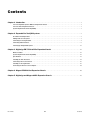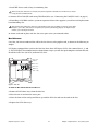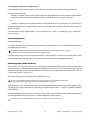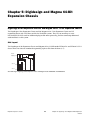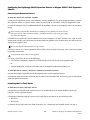
1
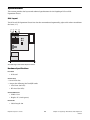
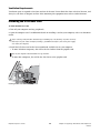
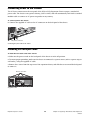
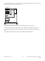
Pro Tools® Expanded Systems Guide Version 8.0.3 Legal Notices This guide is copyrighted ©2009 by Avid Technology, Inc. (hereafter “Avid”), with all rights reserved. Under copyright laws, this guide may not be duplicated in whole or in part without the written consent of Avid. 003, 96 I/O, 96i I/O, 192 Digital I/O, 192 I/O, 888|24 I/O, 882|20 I/O, 1622 I/O, 24-Bit ADAT Bridge I/O, AudioSuite, Avid, Avid DNA, Avid Mojo, Avid Unity, Avid Unity ISIS, Avid Xpress, AVoption, Axiom, Beat Detective, Bomb Factory, Bruno, C|24, Command|8, Control|24, D-Command, D-Control, D-Fi, D-fx, D-Show, D-Verb, DAE, Digi 002, DigiBase, DigiDelivery, Digidesign, Digidesign Audio Engine, Digidesign Intelligent Noise Reduction, Digidesign TDM Bus, DigiDrive, DigiRack, DigiTest, DigiTranslator, DINR, D-Show, DV Toolkit, EditPack, Eleven, HD Core, HD Process, Hybrid, Impact, Interplay, LoFi, M-Audio, MachineControl, Maxim, Mbox, MediaComposer, MIDI I/O, MIX, MultiShell, Nitris, OMF, OMF Interchange, PRE, ProControl, Pro Tools M-Powered, Pro Tools, Pro Tools|HD, Pro Tools LE, QuickPunch, Recti-Fi, Reel Tape, Reso, Reverb One, ReVibe, RTAS, Sibelius, Smack!, SoundReplacer, Sound Designer II, Strike, Structure, SYNC HD, SYNC I/O, Synchronic, TL Aggro, TL AutoPan, TL Drum Rehab, TL Everyphase, TL Fauxlder, TL In Tune, TL MasterMeter, TL Metro, TL Space, TL Utilities, Transfuser, Trillium Lane Labs, Vari-Fi Velvet, X-Form, and XMON are trademarks or registered trademarks of Digidesign and/or Avid Technology, Inc. Xpand! is Registered in the U.S. Patent and Trademark Office. All other trademarks are the property of their respective owners. Product features, specifications, system requirements, and availability are subject to change without notice. Guide Part Number 9320-6429-00 REV A 11/09 Documentation Feedback At Avid, we're always looking for ways to improve our documentation. If you have comments, corrections, or suggestions regarding our documentation, email us at [email protected]. Contents Chapter 1. Introduction . . . . . . . . . . . . . . . . . . . . . . . . . . . . . . . . . . . . . . . . . . . . . . . . . . . . . . . . . . . . . . . . . . . . . . . . . . . 1 Pro Tools Expanded Systems Without an Expansion Chassis . . . . . . . . . . . . . . . . . . . . . . . . . . . . . . . . . . . . . . . . . . . . . 1 Pro Tools with an Expansion Chassis . . . . . . . . . . . . . . . . . . . . . . . . . . . . . . . . . . . . . . . . . . . . . . . . . . . . . . . . . . . . . . . 1 System Requirements and Compatibility . . . . . . . . . . . . . . . . . . . . . . . . . . . . . . . . . . . . . . . . . . . . . . . . . . . . . . . . . . . . 1 Chapter 2. Expanded Pro Tools|HD Systems . . . . . . . . . . . . . . . . . . . . . . . . . . . . . . . . . . . . . . . . . . . . . . . . . . . . . . . 2 Slot Order and Sample Rates . . . . . . . . . . . . . . . . . . . . . . . . . . . . . . . . . . . . . . . . . . . . . . . . . . . . . . . . . . . . . . . . . . . . 2 Adding Cards to Your System . . . . . . . . . . . . . . . . . . . . . . . . . . . . . . . . . . . . . . . . . . . . . . . . . . . . . . . . . . . . . . . . . . . . 3 Connecting Pro Tools|HD Cards . . . . . . . . . . . . . . . . . . . . . . . . . . . . . . . . . . . . . . . . . . . . . . . . . . . . . . . . . . . . . . . . . . 4 Connecting Audio Interfaces . . . . . . . . . . . . . . . . . . . . . . . . . . . . . . . . . . . . . . . . . . . . . . . . . . . . . . . . . . . . . . . . . . . . . 6 Powering Up An Expanded System . . . . . . . . . . . . . . . . . . . . . . . . . . . . . . . . . . . . . . . . . . . . . . . . . . . . . . . . . . . . . . . 11 Chapter 3. Digidesign EB-7 PCIe-to-PCIe Expansion Chassis . . . . . . . . . . . . . . . . . . . . . . . . . . . . . . . . . . . . . . 12 What’s Included . . . . . . . . . . . . . . . . . . . . . . . . . . . . . . . . . . . . . . . . . . . . . . . . . . . . . . . . . . . . . . . . . . . . . . . . . . . . . 12 System Requirements and Compatibility . . . . . . . . . . . . . . . . . . . . . . . . . . . . . . . . . . . . . . . . . . . . . . . . . . . . . . . . . . . 12 Specifications . . . . . . . . . . . . . . . . . . . . . . . . . . . . . . . . . . . . . . . . . . . . . . . . . . . . . . . . . . . . . . . . . . . . . . . . . . . . . . . 13 Installing the PCIe Host Card. . . . . . . . . . . . . . . . . . . . . . . . . . . . . . . . . . . . . . . . . . . . . . . . . . . . . . . . . . . . . . . . . . . . 14 Connecting Power to the Chassis . . . . . . . . . . . . . . . . . . . . . . . . . . . . . . . . . . . . . . . . . . . . . . . . . . . . . . . . . . . . . . . . 15 Installing Pro Tools|HD Cards . . . . . . . . . . . . . . . . . . . . . . . . . . . . . . . . . . . . . . . . . . . . . . . . . . . . . . . . . . . . . . . . . . . 15 Connecting the Chassis to the Computer . . . . . . . . . . . . . . . . . . . . . . . . . . . . . . . . . . . . . . . . . . . . . . . . . . . . . . . . . . . 18 Chapter 4. Magma PE6R4 6-Slot Expansion Chassis . . . . . . . . . . . . . . . . . . . . . . . . . . . . . . . . . . . . . . . . . . . . . . 20 Chapter 5. Digidesign and Magma 64-Bit Expansion Chassis . . . . . . . . . . . . . . . . . . . . . . . . . . . . . . . . . . . . . . 23 Book Title iii Contents Chapter 1: Introduction You can expand your Pro Tools|HD® system by adding Pro Tools|HD cards, either directly in the computer or using an expansion chassis. Expanding your Pro Tools® system will provide increased track count, add to the amount of possible plug-in and mixer processing, and let you connect additional audio interfaces. For a list of system requirements for maximum track count, visit our website (www.avid.com). Pro Tools Expanded Systems Without an Expansion Chassis It is possible to install as many as five Pro Tools cards in some computers. If you require more card slots than your computer has available, you can use an expansion chassis. Pro Tools with an Expansion Chassis You can use an Avid-qualified expansion chassis to increase the number of card slots for your Pro Tools system. An expansion chassis consists of a chassis that provides additional slots for your Pro Tools|HD cards, a host card (installed in your computer), and a cable that connects the host card to the chassis. Some chassis also include a controller card that is installed in the chassis, while some newer expansion chassis have a built-in controller that does not need to be installed. Check with the manufacturer of your chassis for details on the cable requirements for your equipment. System Requirements and Compatibility Pro Tools|HD systems can be used with an Avid-qualified Mac or Windows computer running Pro Tools HD software. Avid can only assure compatibility and provide support for hardware and software it has tested and approved. For complete system requirements and a list of qualified computers, operating systems, hard drives, and third-party devices, refer to the latest information on our website: www.avid.com. PCIx and PCIe Compatibility Information for Windows For maximum track count with Pro Tools HD Accel systems, an HD3 system running either PCIx or PCIe slots are required. If you are using an expansion chassis, the 64-bit expansion chassis card should go in the first 64-bit slot. For more information, see the compatibility pages of our website (www.avid.com). Expanded Systems Guide 1 Chapter 1: Introduction Chapter 2: Expanded Pro Tools|HD Systems This chapter covers the following: • Slot order and sample rate information for all expanded systems. • Instructions for installing an expanded system into slots in your computer (without an expansion chassis). • Instructions for connecting Pro Tools|HD cards together using their FlexCables. These instructions apply to all systems. • Instructions for connecting audio interfaces. These instructions apply to all systems. Slot Order and Sample Rates To ensure maximum track counts and trouble-free operation, it is important that cards are installed in the appropriate slot locations. Cards and Slot Order When installing cards in a computer or an expansion chassis, group cards according to type and install them in the following order, based on your Pro Tools system configuration. Though these recommendations are true for most computers, always verify the slot numbering for your particular computer, as it may differ. Use of a SCSI HBA card in expansion chassis is not supported. Computer Configuration (PCIe) Card Type Order 1 Accel Core (for PCIe) card 2 HD Accel (for PCIe) cards 3 SCSI HBA card Computer Configuration with Expansion Chassis Card Type Order 1 Expansion chassis host card (PCIe) 2 SCSI HBA card Expansion Chassis Configuration (PCIe) Card Type Order 1 Accel Core (PCIe) card 2 HD Accel (PCIe) cards Expanded Systems Guide 2 Chapter 2: Expanded Pro Tools|HD Systems Expansion Chassis Configuration (PCI) Card Type Order 1 HD Core (PCI) card 2 HD Accel (PCI) cards 3 HD Process (PCI) cards Session Sample Rate and Multiple Cards Pro Tools|HD supports sample rates of 44.1 kHz, 48 kHz, 88.2 kHz, 96 kHz, 176.4 kHz, and 192 kHz. However, due to the processing load required for 176.4 kHz and 192 kHz sessions, a maximum of four Pro Tools|HD cards can be used at these higher sample rates. The maximum number of Pro Tools|HD cards supported in a single system is seven. If your system includes more than four Pro Tools|HD cards, the fifth card (and any additional cards) will automatically be taken offline when Pro Tools sessions are set to 176.4 kHz or 192 kHz. You do not need to remove any cards; Pro Tools automatically deactivates the additional cards, and reactivates them when the sample rate is switched to 96 kHz or lower. Any audio interfaces connected to inactive cards will go offline and be unavailable. You should turn off power to offline interfaces connected to cards 5–7 (if any) and re-connect Loop Sync cables (bypassing the inactive interfaces) before starting Pro Tools. Adding Cards to Your System To install Pro Tools cards: Turn off your computer, expansion chassis, and any peripherals. To ensure proper grounding, connect the expansion chassis to a power source (such as a power strip or wall outlet), using the supplied AC cable. 1 Disconnect all cables attached to the computer (such as hard drives, displays, USB and FireWire connections) except for the power cable. 2 3 Open the computer case or expansion chassis. Remove the metal access port cover behind the slot you want to use by removing the screw and sliding the cover out from the access port. 4 Before handling any card, discharge static electricity from your clothes or body by touching a grounded metal surface, such as the power supply case inside your computer. 5 Install the HD Core (for PCI) or Accel Core (for PCIe) card in the lowest-numbered slot, as follows: • On most Windows computers, this will be the slot farthest from the graphics card. Refer to your computer’s documentation to verify slot order. • In a Mac, slot order varies depending on the computer model. For details, see “Mac Reference” on page 4. • For systems with an expansion chassis, see the chapter for your model of chassis. 6 Install HD Accel (for PCI or PCIe) cards in the next slots. Group cards of the same type together (for example, put all HD Accel cards next to each other). Expanded Systems Guide 3 Chapter 2: Expanded Pro Tools|HD Systems 7 Install HD Process cards (if any) in remaining slots. Make sure the first card is the core card for your system. Expansion cards (HD Accel or HD Process) cannot occupy the lowest-numbered slot. 8 Connect all Pro Tools|HD cards using TDM FlexCables (see “Connecting Pro Tools|HD Cards” on page 4). 9 If installing a SCSI HBA card in a system or expansion chassis that supports it, install it in the highest numbered remaining slot. Run DigiTest after making any changes to your hardware setup (such as adding or removing cards, audio interfaces, sync cables, and so on) to verify that your system is functioning properly. For DigiTest information, refer to the DigiTest Guide. 10 Secure each card in place with the slot access port screws you removed earlier. Mac Reference On a Mac, the lowest-numbered slot will be the slot closest to the graphics card, as shown in the following examples: PCI Express-equipped Macs (such as the Mac Pro) have three PCI Express (PCIe) slots (named slots 2, 3, and 4). The PCI Express slot numbers increase from bottom to top as you face the open computer case from the side. Install the Accel Core (for PCIe) card into PCI slot 2. PCIe slot 4 (hidden) PCIe slot 3 PCIe slot 2 AGP slot 1 (video card) Figure 1. Mac Pro To Install an HD card into Slot 4 on a Mac Pro: 1 Remove all SATA drive trays from the Mac Pro. 2 Place the rear of card into the access port. 3 Move the front of the card up and line it up with the PCIe slot and seat the card in the slot. 4 Replace the SATA drive trays. Expanded Systems Guide 4 Chapter 2: Expanded Pro Tools|HD Systems Connecting Pro Tools|HD Cards Each Pro Tools|HD card has two ports along the top of the card, labelled Port A and Port B. The FlexCable has two connectors, also labeled Port A and Port B, to ensure proper connection. Data communication across cards is achieved by connecting Port B of the first card to Port A of the next card with a TDM FlexCable. The first FlexCable always goes from Port B on the core card to Port A on the first expansion card, as described in the following steps. To connect Pro Tools|HD cards with the TDM FlexCable: Shape the FlexCable before installing it on your Pro Tools|HD cards by grasping the cable with both hands with its printed side facing you and moving the Port B portion of the cable away from you and outwards, as shown below. Do not bend the cable more than you need to, as you may damage the traces in the cable. 1 Preparing TDM FlexCable for installation 2 Turn the cable on its side, so that the connectors are facing downwards, and Port A is the higher side. Port A Port B Orienting the FlexCable Slide the FlexCable into the notch of the second card, so that the Port B connector of the FlexCable can be aligned with Port B of the first card; and the Port A connector of the FlexCable can be aligned with Port A of the second card as shown below. 3 Port A connector Port B connector HD Accel (or Process) HD Core Inserting TDM FlexCable Expanded Systems Guide 5 Chapter 2: Expanded Pro Tools|HD Systems Connect the Port A connector of the FlexCable to Port A on the second card. Push down gently but firmly until the cable is fully connected to the card. Attach the other end of the FlexCable (labeled Port B) to Port B on the first card. 4 HD Accel (or Process) card in PCI slot 3 Port Port B B PortAA Port Port Port B B PortAA Port HD Core card in PCI slot 2 Top view of TDM FlexCable connections for two Pro Tools|HD cards Verify the connection. Make sure the FlexCable ports seat flat against the sockets on the Pro Tools|HD cards, and are firmly attached. 5 For systems with more than two cards, connect each additional card to its preceding card. Use FlexCables to connect card pairs together, as described above, until all cards are connected. (Each expansion card is packaged with a FlexCable.) 6 7 Close the computer case. Connecting Audio Interfaces All Pro Tools|HD audio interfaces require DigiLink connections. When using multiple interfaces, you must also connect Loop Sync between all Pro Tools|HD audio interfaces. When using multiple Legacy I/Os (Pro Tools 24|MIX™-series interfaces such as the 888|24 I/O™ and 882|20 I/O™) you must connect Slave Clock to all Pro Tools|24|MIX-series audio interfaces. Recommended Ordering of Interfaces If your setup includes different types of audio interfaces, install them in the following order: 192 I/O or 192 Digital I/O Use as the primary audio interface. These interfaces provide the highest fidelity clock source for your system. If you have at least one 192 I/O™ or 192 Digital I/O™ in your Pro Tools system, it should be the primary audio interface and Loop Sync master. 96 I/O Use as the primary interface (if a 192 I/O or 192 Digital I/O is not installed), or as an expansion inter- face connected to the Expansion port of the primary interface. 96i I/O Use as the primary interface if no other Pro Tools|HD interfaces are installed, or as an expansion inter- face connected to the Expansion port of another Pro Tools|HD interface. Legacy I/Os See “Connecting Legacy Audio Interfaces” on page 8. Expanded Systems Guide 6 Chapter 2: Expanded Pro Tools|HD Systems DigiLink Connections The DigiLink cable connects Pro Tools|HD cards and audio interfaces. A single Digi-Link connector carries up to 32 channels of bidirectional audio information. These 32 channels are broken up into 2 groups of 16 channels: Group A = Channels 1–16, Group B = Channels 17–32. The maximum number of DigiLink cables supported on a single system is ten (for session sample rates up to 96 kHz) or eight (for session sample rates of 176.4 kHz or 192 kHz). Use the 12-foot DigiLink cable included with each Pro Tools|HD card to connect the card to a Pro Tools audio interface. The primary audio interface, which functions as the Loop Sync master for other interfaces in the system, must be connected to the HD Core card. You can purchase optional DigiLink cables of differing lengths (25-foot, 50-foot, and 100-foot), depending on the needs of your studio configuration. Use the 18-inch DigiLink cable, included with each Pro Tools|HD audio interface, when connecting a secondary Pro Tools|HD audio interface to the Expansion port of another Pro Tools|HD audio interface. HD Core or Accel Core card 18-inch DigiLink cable 12-foot DigiLink cable Loop Sync cables Figure 2. Two 96 I/Os, 32-channel HD Core or Accel Core card 18-inch DigiLink cable 12-foot DigiLink cable Loop Sync cables TDM FlexCable Loop Sync cables HD Accel card or HD Process card 12-foot DigiLink cable Figure 3. Three 96 I/Os, 48-channel Expanded Systems Guide 7 Chapter 2: Expanded Pro Tools|HD Systems To make DigiLink connections to audio interfaces: 1 Connect the primary audio interface to the HD Core card with the provided 12-foot DigiLink cable. 2 Do one of the following: • Connect a secondary Pro Tools|HD audio interface to the Expansion port on the primary audio interface using the 18-inch DigiLink cable (included with the audio interface). See Figure 2 on page 7. – or – • Connect a secondary Pro Tools|HD interface to the DigiLink on the next card (HD Accel or HD Process). Connect additional Pro Tools|HD audio interfaces to subsequent Pro Tools|HD audio interfaces or cards. See Figure 3 on page 7. 3 If connecting a Legacy audio interface (such as the 888|24 I/O), refer to “Connecting Legacy Audio Interfaces” on page 8. 4 Connecting Loop Sync To connect Loop Sync: Connect the Loop Sync Out of the primary interface to the Loop Sync In of the second interface with the provided Loop Sync cables. 1 When using a SYNC peripheral, the SYNC peripheral is considered the primary interface of the Loop Sync connection. For more information, refer to the SYNC peripheral guide. 2 Connect the Loop Sync Out of the second interface to the Loop Sync In of the next interface and so forth. 3 Connect the Loop Sync Out of the last interface to the Loop Sync In of the primary interface. Connecting Legacy Audio Interfaces Each 192 I/O, 192 Digital I/O, and 96 I/O™ can support 16 channels of audio to and from legacy audio interfaces, or Legacy I/Os. These include the 888|24 I/O, 882|20 I/O, 1622 I/O™, 24-bit ADAT Bridge I/O™, and the original ADAT Bridge I/O. The 888 I/O and 882 I/O interfaces are not supported with Pro Tools HD. (The 96i I/O does not provide a Legacy port.) The Legacy Peripheral port functions like the Expansion port. The Legacy port and the Expansion port both use Group B: Channels 17–32. you must choose between the Legacy port and the Expansion port in the Pro Tools Hardware Setup dialog. A single Legacy I/O can be connected to the Legacy Peripheral port using any Pro Tools MIX peripheral cable. Two Legacy I/Os can be connected to a single Legacy Peripheral port using a “Y” cable (16-channel Peripheral Cable Adapter). The maximum number of Legacy I/Os that can be connected to a Pro Tools|HD system is eight; requiring four Pro Tools|HD audio interfaces and four 16-channel Peripheral Cable Adapters. The Legacy port is not available in Pro Tools sessions at sample rates greater than 48 kHz. Expanded Systems Guide 8 Chapter 2: Expanded Pro Tools|HD Systems To connect Legacy audio interfaces: 1 Connect one end of a Pro Tools|24 MIX peripheral cable to the Legacy port on a 192 I/O, 192 Digital I/O, or 96 I/O. 2 Connect the other end of the cable to your MIX-compatible audio interface. 3 Connect the External Clock Out of the primary interface to the Slave Clock In of the Legacy audio interface using a BNC cable. If connecting two Legacy peripherals, connect the Slave Clock Out of the first Legacy peripheral to the Slave Clock In of the second Legacy peripheral. 4 Do not connect the Slave Clock Out of the last Legacy peripheral to the clock input on any Pro Tools|HD interface. If using an 888|24 I/O, do not power on the 888|24 until you are ready to declare it in the Hardware Setup dialog, after launching Pro Tools. See the Pro Tools|HD Getting Started Guide for more information. Identifying Audio Interfaces If you have multiple audio interfaces of the same type connected to your system, you can confirm the identity of each interface. This ensures that you choose the appropriate interface in the Peripherals list when you define its inputs and outputs in the Hardware Setup dialog. To identify audio interfaces in your system: 1 Choose Setup > Hardware. 2 From the Peripherals list, select an audio interface connected to your system. 3 Click Main. Select the Identify option, located in the lower left corner of the Hardware Setup dialog. This illuminates all the LEDs on the front panel of the selected audio interface. 4 5 Make a note of which interface in your studio setup corresponds to the identified interface. 6 Repeat the above steps for each additional audio interface in your setup. Number of I/O Channels in Expanded Systems You can add audio interfaces to your system to increase the number of available channels of hardware input and output. Hardware input and output includes digital and analog connections. Number of Channels of I/O Pro Tools|HD audio interfaces provide varying numbers of hardware input and output connectors and ports, a certain number of which can be utilized simultaneously. For specifications of Pro Tools|HD I/Os, refer to the Pro Tools|HD Getting Started Guide. Expanded Systems Guide 9 Chapter 2: Expanded Pro Tools|HD Systems The 96 I/O and standard 192 I/O are examples of symmetrical I/O, where there are the same number of input channels as output channels. For example, there are 8 analog inputs and 8 analog outputs. Though these I/Os provides many analog and digital connectors on their back panels, they support a total of 16 channels of simultaneous, discrete input and output. This means you can be listening to or recording as many as 16 channels of input while simultaneously monitoring or sending as many as 16 channels of output through a single I/O. The 192 I/O can be expanded by adding a 192 A/D or 192 D/A Expansion card to increase the number of analog inputs or analog outputs to 16. Expanded 192 I/O interfaces are an example of asymmetrical I/O when they have a different number of input channels or output channels. For example, when a 192 A/D card is installed on a standard 192 I/O, the I/O now has 16 analog inputs and 8 analog outputs. On Expanded 192 I/Os, the maximum number of simultaneous, discrete inputs and outputs is still 16. Because of the way in which 192 I/O interfaces can be expanded, the maximum number of channels of digital or analog I/O possible with an expanded Pro Tools|HD system depends on whether you use digital or analog connections, and whether you require a symmetrical or asymmetrical number of input and output channels, as explained in the following examples: Maximum I/O Configuration Examples Pro Tools|HD System with Ten Interfaces (Session Sample Rates Up to 96 kHz) Digital Up to 160 input and output channels (requires ten 192 Digital I/O interfaces) Analog Up to 120 simultaneous channels of input and output. Requires the following: • Five 192 I/O interfaces modified for 16 analog inputs and 8 analog outputs (requires adding an A/D card to each interface) • Five 192 I/O interfaces modified for 8 analog inputs and 16 analog outputs (requires adding a D/A card to each interface) Pro Tools|HD System with Eight Interfaces (Session Sample Rates Higher than 96 kHz) Digital Up to 128 channels of input and output (requires eight 192 Digital I/O interfaces) Analog Up to 96 simultaneous channels of input and output. Requires the following: • Four 192 I/O interfaces modified for 16 analog inputs and 8 analog outputs (requires adding an A/D card to each interface) • Four 192 I/O interfaces modified for 8 analog inputs and 16 analog outputs (requires a D/A card added each interface) If you need more analog inputs and do not need all available analog outputs, use more A/D cards and fewer D/A cards. Conversely, to increase output capacity, use more D/A cards instead of A/D cards. Expanded Systems Guide 10 Chapter 2: Expanded Pro Tools|HD Systems Powering Up An Expanded System This section provides general information for powering up expanded systems. Make sure to have the expansion chassis cable connected to both the expansion chassis and the computer before powering up. If the cable becomes disconnected from the computer while the system is powered on, shut down power to the computer and then the expansion chassis before reconnecting. Before you connect your expansion chassis or install cards in it, make sure to turn off both the chassis and your computer. Starting Up and Shutting Down Your System Whenever you start your system, turn on all of your system components in a specific order. To start up your Pro Tools system: 1 Make sure all your equipment is off (including your computer). 2 Turn on the expansion chassis. 3 Turn on any external hard drives. Wait approximately ten seconds for them to spin up to speed. 4 Turn on any MIDI interfaces and devices or any synchronization peripherals. 5 Lower the volume of all output devices, then turn on your Pro Tools audio interfaces. Wait at least fifteen seconds for the audio interfaces to initialize and the status LEDs to stop flashing. 6 Turn on your computer. To shut down your Pro Tools system: 1 Lower the volume of all output devices and monitors. 2 Shut down your computer. 3 Turn off Pro Tools audio interfaces. 4 Turn off any MIDI interfaces or devices. 5 Turn off external hard drives. 6 Turn off your expansion chassis. Expanded Systems Guide 11 Chapter 2: Expanded Pro Tools|HD Systems Chapter 3: Digidesign EB-7 PCIe-to-PCIe Expansion Chassis The Digidesign EB-7 PCIe-to-PCIe Expansion Chassis is a 7-slot expansion chassis for Pro Tools|HD systems. The PCIe-to-PCIe Expansion Chassis lets you install up to seven Pro Tools|HD (PCIe) cards for additional plug-in and mixer processing, and for connecting additional audio interfaces to the system. What’s Included • Expansion Chassis: 4U, 19-inch rackmount enclosure • PCIe Host Card: Dedicated card that is installed in the host computer and provides the connection to the chassis • iPass cable: 3-meter cable to connect the host card to the PCIe-to-PCIe Expansion Chassis • AC power cable System Requirements and Compatibility The Digidesign PCIe-to-PCIe Expansion Chassis can be used with Digidesign-qualified computers running Pro Tools HD software. In order to achieve maximum track count with an expansion chassis, there may be additional system requirements beyond those for Pro Tools|HD systems without an expansion chassis. Avid can only assure compatibility and provide support for hardware and software it has tested and approved. For complete system requirements and a list of qualified computers, operating systems, hard drives, and third-party devices, refer to the latest information on our website: www.avid.com Expanded Systems Guide 12 Chapter 3: Digidesign EB-7 PCIe-to-PCIe Expansion Chassis Specifications This section provides slot layout and technical specifications for the Digidesign PCIe-to-PCIe Expansion Chassis. Slot Layout The PCIe-to-PCIe Expansion Chassis has slots that are numbered sequentially, right-to-left when viewed from the front (1–7). 7 6 5 4 3 2 1 Slot numbering for PCIe-to-PCIe Expansion Chassis Hardware Specifications Host Card • PCIe card Chassis Slots • Seven PCIe slots • Accepts the following Pro Tools|HD cards: • Accel Core (for PCIe) • HD Accel (for PCIe) Chassis Dimensions • Width: 19 in • Height: 4U (4 rack spaces) iPass Cable • Cable Length: 3m Expanded Systems Guide 13 Chapter 3: Digidesign EB-7 PCIe-to-PCIe Expansion Chassis Ventilation Requirements Ventilation space is required at the front and rear of the unit. Do not block the front or back of the unit, and always be sure there is adequate air flow when mounting this equipment into racks or studio furniture. Installing the PCIe Host Card To install the PCIe host card: 1 Turn off your computer and any peripherals. Open the computer case. For additional details on installing a card in your computer, refer to its documentation. 2 Before removing cards from their antistatic bags or handling any card, discharge any static electricity that may be on your clothes or body by touching a grounded metal surface (such as the power supply case inside your computer). 3 Install the PCIe host card in the lowest numbered available slot in your computer. • In most Windows computers, this will be the slot farthest from the graphics card. Refer to your computer’s documentation to verify slot order. • In most Mac computers, this will be the slot closest to the graphics card. Installing the PCIe host card in the computer Expanded Systems Guide 14 Chapter 3: Digidesign EB-7 PCIe-to-PCIe Expansion Chassis Connecting Power to the Chassis The AC Power connector on the rear panel of the PCIe-to-PCIe Expansion Chassis accepts a standard AC power cable. The chassis is auto power-selecting (100V to 240V) and will automatically work with a standard modular cable to connect to AC power receptacles in any country. To connect power to the chassis: Connect the supplied AC cable to the AC connector on the back panel of the chassis. AC power connector Connecting the power cable to the chassis Installing Pro Tools|HD Cards To install Pro Tools audio cards in the chassis: 1 Make sure the power switch on the back panel of the chassis is in the off position. To ensure proper grounding, make sure the chassis is connected to a power source (such as a power strip or wall outlet), using the supplied AC cable. 2 Remove the 6 screws from the top cover of the expansion chassis, and slide the cover toward the back panel to remove it. 3 Remove 6 screws 0 1 2 3 4 5 6 7 Top panel screws Expanded Systems Guide 15 Chapter 3: Digidesign EB-7 PCIe-to-PCIe Expansion Chassis Install the Pro Tools Accel Core card in the first PCIe slot of the expansion chassis. (This is the first slot on the right when the chassis is viewed from the front.). 4 7 6 5 4 3 2 1 Slot numbering for the PCIe-to-PCIe Expansion Chassis 5 Install the remaining HD Accel cards in successively numbered card slots in the chassis. 6 Connect all Pro Tools cards with TDM FlexCables. See “Connecting Pro Tools|HD Cards” on page 4. After connecting cards with FlexCables, connect audio interfaces. See “Connecting Audio Interfaces” on page 6. 7 8 After connecting audio interfaces, return here and complete the installation process. Expanded Systems Guide 16 Chapter 3: Digidesign EB-7 PCIe-to-PCIe Expansion Chassis Example The following table shows one possible configuration of cards (and audio interface connections), using all slots in the PCIe-to-PCIe Expansion Chassis. Table 4. Chassis cards with multiple audio interfaces Slot Card Slot 1 Accel Core (Interface #1 and #2) Slot 2 HD Accel (Interface #3 and #4) Slot 3 HD Accel (Interface #5 and #6) Slot 4 HD Accel (Interface #7 and #8) Slot 5* HD Accel (Interface #9 and #10) Slot 6* HD Accel Slot 7* HD Accel * Card only available at 44.1 kHz, 48 kHz, 88.2 kHz, and 96 kHz Only Pro Tools|HD (for PCIe) cards can be installed in the chassis. PCI cards are not supported. For more information on using multiple audio interfaces, see “Number of I/O Channels in Expanded Systems” on page 9. Expanded Systems Guide 17 Chapter 3: Digidesign EB-7 PCIe-to-PCIe Expansion Chassis Connecting the Chassis to the Computer To connect the chassis to the computer: Connect the x4 end of the iPass cable to the iPass cable port on the chassis. Make sure the connection is secure. 1 x4 connector x8 connector Detail of iPass cable connectors iPass cable port Connecting the iPass cable to the chassis 2 Connect the x8 end of the iPass cable to the port on the PCIe host card in the computer. Make sure the connection is secure. iPass cable port Connecting the iPass cable to the PCIe host card Starting Up Your System Whenever you start up your system, turn on all of your system components in a specific order. To start up your Pro Tools system: 1 Make sure all your equipment is off (including your computer). Expanded Systems Guide 18 Chapter 3: Digidesign EB-7 PCIe-to-PCIe Expansion Chassis 2 Move the power switch on the back panel of the PCIe-to-PCIe Expansion Chassis to the On position. 0 1 2 3 4 5 6 7 Power switch Location of the back panel power switch 3 Press the power switch on the front panel of the PCIe-to-PCIe Expansion Chassis to turn on the chassis. The Power switch LED lights when the chassis is fully powered. Power switch Location of the front panel power switch 4 Turn on any external hard drives. Wait approximately ten seconds for them to spin up to speed. 5 Turn on any MIDI interfaces and devices, or synchronization peripherals. 6 Lower the volume of all output devices, then turn on your Pro Tools audio interfaces. Wait at least fifteen seconds for the audio interfaces to initialize and the status LEDs to stop flashing. 7 Turn on your computer. Shutting Down Your System To shut down your Pro Tools system: 1 Lower the volume of all output devices and monitors. 2 Shut down your computer. 3 Turn off Pro Tools audio interfaces. 4 Turn off any MIDI interfaces or devices. 5 Turn off external hard drives. 6 Press the power switch on the front panel of the expansion chassis. Expanded Systems Guide 19 Chapter 3: Digidesign EB-7 PCIe-to-PCIe Expansion Chassis Chapter 4: Magma PE6R4 6-Slot Expansion Chassis Magma PE6R4 6-Slot Expansion Chassis The Magma PE6R4 expansion chassis is a six-slot PCI expansion chassis with a PCIe host card for Pro Tools|HD systems. The PE6R4 lets you install up to six Pro Tools|HD (for PCI) cards for additional plug-in and mixer processing, and for connecting additional audio interfaces to the system. A PCI host card is not available for the Magma PE6R4 expansion chassis Slot Layout for Magma PE6R4 6-Slot Expansion Chassis The Magma PE6R4 expansion chassis has PCI slots that are numbered sequentially, right-to-left from the front (1–6). Slot 1 Slot 6 Slot numbering for Magma model PE6R4 Expanded Systems Guide 20 Chapter 4: Magma PE6R4 6-Slot Expansion Chassis Configuring the Magma PE6R4 6-Slot Expansion Chassis Connecting the Expansion Chassis To install the PCIe host card in the computer: Turn off the expansion chassis, your computer, and any peripherals. To ensure proper grounding, connect the expansion chassis to a power source (such as a power strip or wall outlet), using the supplied AC cable. 1 Open the computer case. For additional details on installing a card in your computer, refer to its documentation. 2 Before removing cards from their antistatic bags or handling any card, discharge any static electricity that may be on your clothes or body by touching a grounded metal surface (such as the power supply case inside your computer). 3 Install the host card in the lowest numbered PCIe slot in your computer. • On most Windows PCs, this will be the slot farthest from the graphics card. Refer to your computer’s documentation to verify slot order. • On most Macs, this will be the slot closest to the graphics card. Connect the host card to the chassis: 1 Attach one end of each Infiniband cable to the two connectors (labeled x1 and x3) on the host card. Attach the other end of each cable to the corresponding connector on the expansion chassis. Each cable should be attached to connectors with the same label (x1 or x3) on both ends. 2 Refer to the expansion chassis guide for detailed instructions on connecting the Infiniband cables. 3 If using a SCSI HBA, do one of the following: • On Windows computers, install the SCSI HBA in the 64-bit slot closest to the graphics card. – or – • On Mac computers, install the SCSI HBA card in the highest numbered remaining slot. Installing the Pro Tools Cards To install Pro Tools audio cards in the chassis: 1 Install the Pro Tools|HD Core card in the first slot of the expansion chassis. 2 Install the remaining cards in successive PCI card slots in the chassis, in the following order: • HD Accel • HD Process Only Pro Tools|HD (for PCI) cards can be installed in the chassis. PCIe cards are not supported. 3 Connect all Pro Tools cards with TDM FlexCables. See “Connecting Pro Tools|HD Cards” on page 4. Expanded Systems Guide 21 Chapter 4: Magma PE6R4 6-Slot Expansion Chassis Magma PE6R4 (Example Configuration) Table 5. Chassis cards with multiple audio interfaces Slot Card Slot 1 HD Core (Interface #1 and #2) Slot 2 HD Accel (Interface #3 and #4) Slot 3 HD Accel (Interface #5 and #6) Slot 4 HD Accel (Interface #7 and #8) Slot 5* HD Accel (or Process) (Interface #9 and #10) Slot 6* HD Accel (or Process) * Card only available at 44.1 kHz, 48 kHz, 88.2 kHz, and 96 kHz Connecting Audio Interfaces See “Connecting Audio Interfaces” on page 6. Expanded Systems Guide 22 Chapter 4: Magma PE6R4 6-Slot Expansion Chassis Chapter 5: Digidesign and Magma 64-Bit Expansion Chassis Digidesign 64-Bit Expansion Chassis and Magma 64-Bit 7-Slot Expansion Chassis The Digidesign 64-bit Expansion Chassis and the Magma 64-bit 7-slot Expansion Chassis are PCI expansion chassis with a PCI host card for Pro Tools|HD systems. They let you install up to seven Pro Tools|HD (for PCI) cards for additional plug-in and mixer processing, and for connecting additional audio interfaces to the system. Slot Layout The Digidesign 64-Bit Expansion Chassis and Magma 64-bit, 33 MHz model P7R464-D1 and P7R464C1.5-D1 chassis have slots that are numbered sequentially, right-to-left from the front (1–7). Power Supply Slot 1 Slot 7 Slot numbering for Digidesign 64-Bit Expansion Chassis and Magma models P7R464-D1 and P7R464C1.5 Expanded Systems Guide 23 Chapter 5: Digidesign and Magma 64-Bit Expansion Chassis Configuring the Digidesign 64-Bit Expansion Chassis or Magma 64-Bit 7-Slot Expansion Chassis Connecting the Expansion Chassis To install the chassis host card in the computer: Turn off the expansion chassis, your computer, and any peripherals. To ensure proper grounding, connect the expansion chassis to a power source (such as a power strip or wall outlet), using the supplied AC cable. 1 Open the computer case. For additional details on installing a card in your computer, refer to its documentation. 2 Before removing cards from their antistatic bags or handling any card, discharge any static electricity that may be on your clothes or body by touching a grounded metal surface (such as the power supply case inside your computer). Install the host card in the lowest numbered slot in your computer. On most Windows PCs (such as an HP Workstation xw8000), this will be the slot furthest from the graphics card. On most Macs, this will be the slot closest to the graphics card. 3 Refer to your computer’s documentation to verify slot order. 4 Attach a 1 meter or 1.5 meter expansion chassis cable to the host card. If necessary, refer to the chassis guide for specific instructions. 6-foot expansion chassis cables are not supported. 5 If using a SCSI HBA, do one of the following: • On Windows computers, install the SCSI HBA in the 64-bit slot closest to the graphics card. – or – • On Mac computers, install the SCSI HBA card in the highest numbered remaining slot. To install the chassis controller card (if one is required by your model of chassis): 1 Install the Magma Controller card in the Expansion Slot of the expansion chassis. Attach the other end of the expansion chassis cable to the controller card. If necessary, refer to the Magma guide for specific instructions. 2 Installing the Pro Tools Cards To install Pro Tools audio cards in the chassis: Install the Pro Tools|HD Core card in the first slot (numbered slot 4 in Magma models P7R-D1 and P7RQ-D1) of the expansion chassis. 1 2 Install the remaining cards in successive PCI card slots in the chassis, in the following order: • HD Accel • HD Process 3 Connect all Pro Tools cards with TDM FlexCables. See “Connecting Pro Tools|HD Cards” on page 4. Expanded Systems Guide 24 Chapter 5: Digidesign and Magma 64-Bit Expansion Chassis Magma 64-bit 7-Slot (Example Configuration) Table 6. Chassis cards with multiple audio interfaces: Slot Card Exp. Slot Chassis Controller card (not all models) Slot 1 HD Core (Interface #1 and #2) Slot 2 HD Accel (interface #3 and #4) Slot 3 HD Accel (Interface #5 and #6) Slot 4 HD Accel (Interface #7 and #8) Slot 5* HD Accel (or HD Process) (Interface #9 and #10) Slot 6* HD Accel (or HD Process) Slot 7* HD Accel (or HD Process) * Card only available at 44.1 kHz, 48 kHz, 88.2 kHz, and 96 kHz Connecting Audio Interfaces See “Connecting Audio Interfaces” on page 6. Achieving Maximum Voice Counts Compatible 64-bit expansion chassis will provide maximum voice count for most stereo sessions up to a 96 kHz sample rate, but will have a reduced voice count at 176.4 and 192 kHz sample rates. Using a 64-bit expansion chassis with surround sessions will yield a reduced voice count at 44.1 and 48 kHz sample rates. For a complete and current list of supported configurations of computers, expansion chassis, and hard drives for maximum voices with Pro Tools systems, visit our website (www.avid.com). Expanded Systems Guide 25 Chapter 5: Digidesign and Magma 64-Bit Expansion Chassis www.digidesign.com DIGIDESIGN 2001 Junipero Serra Boulevard Daly City, CA 94014-3886 USA TECHNICAL SUPPORT (USA) Visit the Digidesign Online Support Center at www.digidesign.com/support PRODUCT INFORMATION For company and product information, visit us on the web at www.digidesign.com