1
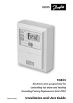
FP975
7-day electronic
programmer
Installation & User Instructions
®
Certification Mark
Index
Installation
Product specification
DIL switch settings
New Installation
Existing Installation
Wiring
Wiring Conversion
User
What is a programmer?
Your programmer
Preset programmes
Before you start
AM/PM or 24hr display
Setting the Time and Day
Accepting the preset programmes
Changing the preset programmes
Programming heating - 5/2 day
Programming heating - 7 day
Programming the hot water
Running the programme
Temporary overrides
Changing clocks forward/back
Contact details
2
3
4-5
5-8
9
10-11
12-19
20
21
21
22
22
22-23
23
24
25-26
27-28
29
30
31
32
36
+1HR override
(HEATING)
+1HR override
( HOT WATER)
MAN override
(HEATING)
MAN override
(HOT WATER)
Heating Mode
SELECT
Hot Water
Mode SELECT
Installation Instructions
Please Note:
This product should only be installed by a qualified
electrician or heating installer, and should be in
accordance with the current edition of the IEEE wiring
regulations.
Specification
Power supply
230 Vac ± 15%, 50/60 Hz
Switching action
2 x SPDT voltage free, Type 1BS
Switch rating
10-230 Vac, 3(1)A
Battery back-up
24 hours minimum
Timing Accuracy
±1 min/month
Setting/Running Accuracy
±1 minute
Max. Ambient Temperature
45°C
Dimensions, mm (W, H, D)
148 x 96 x 42
Design standard
EN 60730-2-7
Control Pollution Situation
Degree 2
Rated Impulse Voltage
2.5kV
Ball Pressure Test
75°C
Installation & Specification
Product specification
3
DIL Switch Settings
Before mounting the unit, ensure the 4 DIL switches on the rear of
the unit have been moved to the required settings.
TOP
7 DAY
PUMPED
MK.9
RIGHT
LEFT
DIL switch settings
5/2 DAY
GRAVITY
SET
MK.9 or SET
The FP975 is supplied fitted with a Danfoss Randall SET wallplate.
However the FP975 will also mount directly onto a Danfoss Randall
MK.9 wallplate without the need for wiring changes. However
when used with existing MK.9 wallplates the left hand switch
must be set in the MK.9 position to re-configure the time control
to match MK.9 wiring connections.
PUMPED or GRAVITY
When this switch is in the PUMPED position the Heating and
Water outputs are UNLINKED. When in the GRAVITY position the
Water output is LINKED to the Heating output so that whenever
the Heating is ON the Water will also be ON regardless of the
Water programme.
Place the switch in the PUMPED position if the system being
controlled is a) fully pumped with a mid-position valve, b) fully
pumped with a two port zone valve in each circuit, c) GRAVITY
Hot Water, PUMPED Heating with a two port zone valve with
SPDT auxillary switch in the gravity primary circuit (and wired in
accordance with diagrams on pages 10-11).
4
Place the switch in the GRAVITY position if the system being
controlled is a) fully pumped, but with only a single two port
zone valve in the Heating circuit, b) GRAVITY Hot Water, PUMPED
Heating with no zone valves.
7 Day or 5/2 Day
When both switches are in the 7 DAY position each day of the
week may be programmed with different ON/OFF times. When
both switches are in the 5 DAY/2 DAY position, weekdays (Mon-Fri)
can be programmed with one set of ON/OFF times, and weekends
(Sat-Sun) can be programmed with a different set.
New Installation
When fixing the wallplate note that the terminals are at
the top, and the vertical centre line of the unit lies between
terminals N & L.
2. Surface cables can only enter from below the unit. If
mounted on a plaster box, cables can enter from the rear
through the aperture in the wallplate.
New Installation
1. Fix the wallplate to the wall or plaster box as required.
3. The FP975 offers direct plug-in replacement to the
following models (see overleaf ):
5
6
Horstmann
Danfoss
Randall
Manufacturer
Pumped
Pumped
Tiara 425
Tiara 527
Pumped
Diadem 425
Pumped
Unlinked
SET 5
Tiara 525
Unlinked
922
SET 2*
Unlinked
FP975
Unlinked
Pumped
Model
972
Fully Pumped
Systems Pumped/
Gravity Selector
Position
Direct Plug-In Upgrade for Existing Programmers
New Installation
Gravity
Gravity
Gravity
Gravity
Linked
Linked
Linked
Linked
Gravity
Gravity H.W.
Systems Pumped/
Gravity Selector
Position
SET
SET
SET
SET
SET
SET
MK.9
MK.9
SET
Wallplate
Type
SET
SET
SET
SET
SET
SET
MK.9
MK.9
SET
Mode Sw
Position
MAKE
MODELS
ACL
LS2411, LS522, LS722, LP241, LP522, LP722
Drayton
Tempus 3, Tempus 4, Tempus 7
Landis & Gyr
RWB 2, RWB 2-9, RWB 200, RWB 252, RWB 20,
RWB 40
Glowworm
Mastermind
Potterton
Mini-Minder
If the new unit is replacing an existing time control
having an incompatible wiring configuration, then the
wiring conversions (tables A & B, pages 12-19) will be of
assistance.
4. For wiring connections please refer to diagrams on pages
10-11. Please note, the FP975 does not require an earth
connection, although a terminal is provided for earth
continuity purposes.
New Installation
IMPORTANT NOTE
If the timeswitch to be replaced is listed below it may be worth
considering a FP715 as an alternative to the FP975. The FP715
offers wallplate compatablility for those models listed below,
although some re-wiring may be required.
5. Ensure that the two retaining screws on the top of the
timeswitch are fully unscrewed. Locate the retaining lugs
on the bottom inside surface of the plug-in module under
the wallplate base and hinge the unit upwards until the
module is pressed fully against the top of the wallplate.
Tighten the two screws on the top of the module to secure
the module to the wallplate.
7
6. A small blanking plug is supplied to blank the unused
recessed bottom fixing screw.
7. Before setting the programmes the unit should be RESET
by pressing the recessed button marked R/S. Ensure the
mains power to the control circuit is switched on, and
check the circuits as follows.
8. Use the
(Hot Water) SELECT button to get to the
ON mode to switch the hot water output ON. Adjust the
cylinder thermostat and check that the service operates
correctly. Use the SELECT button to get to OFF mode and
check that the service does not operate.
New Installation
9. Use the
(Heating) SELECT button to get to the ON
mode to switch the heating output ON. Adjust any remote
thermostat(s) and check that the service operates correctly.
Use the SELECT button to get to OFF mode and check that
the service does not operate.
8
Existing Installation
!
Ensure that the power to the existing unit is switched
off prior to removal.
SYSTEMS RE-USING EXISTING WALLPLATE
1. Remove and discard the white test point cover fitted to
the top of the MK.9 wallplate.
2. Slide the small switches on the rear of the module
marked MK.9 - SET to the MK.9 position.
3. Ensure that the two retaining screws on the top of
the timeswitch are fully unscrewed. Firmly press the
module onto the wallplate and tighten the two screws
on the top of the module. An additional fixing screw
to hold the bottom of the unit onto the wallplate
is packed separately and must be fitted. The screw
should be placed into the recessed hole, beneath
the programming flap, adjacent to the COPY button,
screwed through the plastic retaining ring and securely
tightened.
4. Follow steps 6-9 from the “New Installations” section.
Existing Installation
Use the table on page 6 to confirm wallplate compatability.
If the existing wallplate is of the SET pattern, follow
instruction 5-9 from the “New Installations” sections.
Should the existing product be a Danfoss Randall MK.9
time control the instructions below should be followed:
SYSTEMS HAVING INCOMPATIBLE BACKPLATES
Follow the “New Installations” instructions paying particular
attention to item 3).
9
Wiring
For Wiring
Conversion
tables
see pages
12-19
NOTES:
FOR SET2E
LINK
TERMINALS 1 &
5
FP975 ON A
SET
WALLPLATE
For 230 Vac
systems link
L, 2 & 5
Always switch off mains first and never fit programmer
to a live wallplate.
230 Vac Fully Pumped System - Two 2-port Zone Valves
with Aux. Sw. PUMPED switch selection
Wiring
MAINS
fused 3A
N
L
DHW
ON
DHW
COM
DHW
OFF
HTG
ON
HTG
COM
HTG
OFF
1
2
3
4
5
6
N
230
Vac
RMT
ATC
Earths not
shown. Ensure
continuity
throughout
L
DHW
VALVE
HEAT
PLAN
10
HTG VALVE
BOILER
PUMP
230 Vac Controlled Gravity Hot Water - Pumped Heating
System PUMPED switch selection
MAINS
fused 3A
N
L
DHW
ON
DHW
COM
DHW
OFF
HTG
ON
HTG
COM
HTG
OFF
1
2
3
4
5
6
N
L
230
Vac
ATC
RMT
Earths not shown.
Ensure continuity
throughout.
HP28C
BOILER
PUMP
MAINS
fused 3A
N
230
Vac
L
DHW
ON
DHW
COM
DHW
OFF
HTG
ON
HTG
COM
HTG
OFF
1
2
3
4
5
6
Wiring
230 Vac Fully Pumped System - 3-port Mid-position Valve
PUMPED switch selection
N
ATC
L
RMT
HS3
HEAT
SHARE
BOILER
PUMP
Earths not
shown.
Ensure continuity
throughout.
11
WIRING CONVERSIONS
to be used when replacing the following
programmers with the FP975. Some time controls are connected differently
depending on the type of system they are controlling. Consult the column
Table A
DANFOSS RANDALL
FP975 (SET MODE)
Fully Pumped Systems - ensure
Pumped/Gravity switch is in
‘Pumped’ position
WATER
N
L
ON
COM
OFF
N
L
1
2
3
7
6
4
1
5
HORSTMANN 423, AMETHYST 7 & 10
2,3
1
5
-
4
HORSTMANN 424 GEM
2,3
1,10
4
5
6
HORSTMANN LEUCITE 423 & 424
2
1
3
5
4
HONEYWELL ST669
N
L
6
8
7
POTTERTON EP2000, EP3000
N
L
3
-
1
RANDALL 3033
1,7
6
4
-
5
RANDALL 702
N
L
3
6
4
SANGAMO FORM 1 410 & 414
4,5
6
1
3
2
SANGAMO S409/1
N,1,3
L
2
-
-
SANGAMO S409/3
3,6
7
5
-
4
SATCHWELL LIBRA & DHP 2201
1
2
6
7
8
SATCHWELL ET 1401 & 1451
1
2
7
6
8
SMITHS IND. CENTROLLER 90
1
2
5
-
-
SMITHS IND. CENTROLLER 1000
N
L
3
-
1
SWITCHMASTER 800 & 805
N
L
3
-
4
SWITCHMASTER 900 & 9000
N
L
3
-
4
DANFOSS RANDALL 4033
12
MAINS
headed “NOTE This conversion ...” to determine whether Table A (pages 12-15) or
Table B (pages 16-19) should be used. If in any doubt, contact our Technical Services
Department before proceeding with the replacement.
HEATING
NOTE
This conversion applies only if....
ON
COM
OFF
4
5
6
2
-
3
7
-
6
7
8
9
Terminals 5,8 & 10 are LINKED
6
7
8
Terminals 5 & 7 are LINKED
3
5
4
4
5
2
2
-
3
1
5
2
8
-
7
5
-
-
1
-
2
3
4
5
4
3
5
4
-
-
4
-
2
1
-
2
1
-
2
LINK L - 2 - 5
An additional terminal
block may be required
where these
disconnected leads
(or pairs) should be
terminated
A
B
C
D
B
C
D
8
Programme
selectors UNLINKED
A
6,4
3
6
A
B
Programme
selectors UNLINKED
Programme
selectors UNLINKED
C
13
Table A cont..
DANFOSS RANDALL
FP975 (SET MODE)
14
MAINS
WATER
N
L
ON
COM
OFF
N
L
1
2
3
VENNER CHC/W2 (WITH STAT)
N,2,4
L
1
-
-
VENNER CHC/W2 (AIR STAT LINKED)
N,2,4
L
1
-
-
VENNER VENOTROL 80M & 80PM
(WITH AIR STAT)
N,3
L
2
-
1
VENNER VENOTROL 80M & 80PM
(AIR STAT LINKED)
N,3
L
2
-
1
HEATING
NOTE
This conversion applies only if....
ON
COM
OFF
4
5
6
A/S
-
-
3
-
-
A/S
-
4
5
-
4
LINK L - 2 - 5
Used in a system having independent control of water and heating
An additional terminal
block may be required
where these
disconnected leads
(or pairs) should be
terminated
A
B
C
D
A/S 3
A/S 5
15
Table B
DANFOSS RANDALL
FP975 (SET MODE)
Gravity DHW, Pumped Heating Systems
- ensure Pumped/Gravity switch is in
‘Gravity’ position
WATER
N
L
ON
COM
N
L
1
2
DANFOSS RANDALL 102/102E/102E5/102E7
5
3,6
1
-
HORSTMANN 423 DIAMOND POTTERTON 423
N
L,1,3
2
-
HORSTMANN 424 DIAMOND
N
L,1,3
2
-
HORSTMANN CORAL 423 & 424
2,3
1
BOILER
(8)
-
POTTERTON EP2000, EP3000
N
L
3
-
DANFOSS RANDALL 3060 & 3020P
1,7
6
4
-
RANDALL 701
N
L
3
6
SANGAMO M5 410 FORM 4
4,5
3
1,6
-
N,1,3
L
2
-
N,2
L
1,3
-
SATCHWELL LIBRA
1
2
6
7
SMITHS IND. CENTROLLER 100
N
L
3
-
SMITHS IND. CENTROLLER 60
1
2
5
-
SMITHS IND. CENTROLLER 10
N
L
3
-
SMITHS IND. CENTROLLER 70
1
2
5
-
SMITHS IND. CENTROLLER 1000
N
L
3
-
SWITCHMASTER 320 & 350
N
4,L
3
-
SWITCHMASTER 400
N
L
3
-
SWITCHMASTER 600
N
L
3
-
SWITCHMASTER 900 & 9000
N
L
3
-
SANGAMO S409 FORMS 1 & 4
SANGAMO (EARLY MODEL) S410 FORM 4
16
MAINS
NOTE
This conversion
applies only if....
HEATING
OFF
ON
COM
OFF
3
4
5
6
-
2
-
-
-
4
-
-
4
-
LINK L - 2 - 5
An additional terminal
block may be required
where these disconnected
leads (or pairs) should be
terminated
A
B
-
5
6
-
-
5
AIR STAT
(8)
-
-
4,7
5
6
1
4
5
2
A
B
C
-
2
-
-
3
5
4
1
5
2
2
8
-
7
-
5
-
-
-
4
-
-
8
3
4
5
-
2
-
-
1
-
4
-
-
3
-
2
-
-
1,4
-
4
-
-
3
1
4
-
2
-
1
-
-
2
-
1
-
4
2
-
1
-
-
2
4
4
1
-
2
A
B
Programme
selectors LINKED
C
D
D
6,4
1 & 3 are LINKED
4
6
Programme
selectors LINKED
Programme
selectors LINKED
C
17
Table B cont....
DANFOSS RANDALL
FP975 (SET MODE)
WATER
N
L
ON
COM
N
L
1
2
N,A,M
L,L1
V
-
VENNER VENOTROL 80 (AIR STAT)
N,1,
3,4
L
2
-
VENNER VENOTROL 80 (AIR STAT LINKED)
N,1,
3,4
L
2
-
VENNER CHC/W2 (WITH STAT)
N,2,4
L
1
-
VENNER CHC/W2 (AIR STAT LINKED)
N,2,4
L
1
-
VENNER VENOTROL 80P (WITH AIR STAT)
N,1,3
L
2
-
VENNER VENOTROL 80P (AIR STAT LINKED)
N,1,3
L
2
-
VENNER VENOTROL
18
MAINS
HEATING
OFF
ON
COM
OFF
3
4
5
6
-
S,F
-
-
A/S
-
NOTE
This conversion
applies only if....
LINK L - 2 - 5
An additional terminal
block may be required
where these disconnected
leads (or pairs) should be
terminated
A
B
-
T,P
O
-
-
A/S,
5
5
-
-
-
A/S
-
-
-
3
-
-
-
A/S
-
4
-
5
-
4
Used in a system
having control of WATER ONLY or WATER &
HEATING TOGETHER
C
D
A/S,
3
A/S,
5
19
The text below has been edited and approved by the Plain
English Campaign, who has issued a Crystal Mark to be
displayed with it.
What is a programmer?
What is a programmer?
... an explanation for householders.
20
Programmers allow you to set ‘On’ and ‘Off’ time periods.
Some models switch the central heating and domestic hot
water on and off at the same time, while others allow the
domestic hot water and heating to come on and go off at
different times.
Set the ‘On’ and ‘Off’ time periods to suit your own lifestyle.
On some programmers you must also set whether you want
the heating and hot water to run continuously, run under the
chosen ‘On’ and ‘Off’ heating periods, or be permanently off.
The time on the programmer must be correct. Some types
have to be adjusted in spring and autumn at the changes
between Greenwich Mean Time and British Summer Time.
You may be able to temporarily adjust the heating
programme, for example, ‘Override’ , ‘Advance’ or ‘Boost’.
These are explained in the manufacturer’s instructions.
The heating will not work if the room thermostat has switched
the heating off. And, if you have a hot-water cylinder, the
water heating will not work if the cylinder thermostat detects
that the hot water has reached the correct temperature.
User Instructions
Your programmer
The FP975 allows you to switch your heating and hot water on
and off at times that suit you.
Preset Programmes
Your FP975 comes ready programmed with a set of operating
times which often suit most people.
Event No.
Hot Water &
Heating
Mon-Fri
Sat-Sun*
1
1st ON
6:30
7:30
2
1st OFF
8:30
10:00
3
2nd ON
12:00
12:00
4
2nd OFF
12:00
12:00
5
3rd ON
17:00
17:00
6
3rd OFF
22:30
22:30
Overview & Preset Programmes
You can programme up to 3 ON/OFF times per day for the
heating and the hot water and the two systems can be operated
independently.
* Available in 5/2 day mode only
See page 23 for explanations of different settings
If you want to change any of these settings, you can do so by
following the instructions on pages 24-29. First, follow the steps
on page 22-23 to set the correct time and date.
21
Before you start
RESET, 24hr or AM/PM display, Setting Time
Open the flap on the front of the clock. Press the RESET (R/S)
button using a non-metallic object (e.g. pencil/matchstick) until
you hear a click and the red light on the front of the unit flashes
once.
This will reinstate the preset
programmes and sets the time to
12.00pm on Monday (MO).
Choice of 24hr or AM/PM display
Press and hold DAY & NEXT ON/OFF
for 1.5 seconds to toggle between
24hr clock and AM/PM display, as
required.
Setting the correct Time and Day
SETTING THE TIME
Press PROG once.
The words SET TIME will appear at
the top of the display & the time will
flash on and off.
Use the + and - buttons to set the
correct time (press and hold to
change in 10 min increments).
22
SETTING THE DAY
Accepting the preset programmes
If you are happy to use the preset programmes on page 21, you
don’t need to do anything else.
To accept the factory presets just
press the PROG button until the
time appears & the colon in the
display begins to flash.
7
Your unit is now in RUN mode and will control your heating and
hot water according to the preset programmes.
Setting Day, Accepting Preset Programmes
Press DAY repeatedly until the
correct day of the week is displayed.
MO is Monday, TU is Tuesday etc.
23
Before you change the preset programmes
Your installer will have set your unit to operate in one of the
following modes:
5/2 day - one set of programmes for weekdays and another
for weekends (page 25-26).
7 day - different settings for each day of the week
(page 27-28).
Changing Preset Programmes
Please Note
The unit must be programmed in sequence and ON/OFF
times cannot be set out of sequence.
If you want to leave a preset time as it is, simply press NEXT
ON/OFF to move on to the next setting.
Your timeswitch allows you to programme 3 ON and 3 OFF
times each day. If you do not wish to use one of the ON/OFF
settings, simply programme the ON time to be the same as
the OFF time and the setting will not operate.
!
24
If at any time you get confused and need to reset your
timings to the standard programme, press the RESET
button to return to the preset programmes (see page
22).
Programming the heating in
5/2 day mode
Press PROG until SET CH ON
TIME appears at the top of the
display and MOTUWETHFR
appears at the bottom of the
display.
Use the + and - buttons to set
the time you would like your
heating to first come on in the
morning (Event 1).
2.
Press NEXT ON/OFF once
only.
Use the + and - buttons to
set the time you want your
heating to go off (Event 2).
To move to the next setting,
i.e. when you would like your
heating to come on again
(Event 3) press the NEXT ON/
OFF button again.
3.
Programming heating - 5/2 day mode
1.
Continue programming the
central heating system ON
and OFF times for weekday
Events 4, 5 & 6 as in Step 2.
25
4.
Press the DAY button once and
SASU will appear at the bottom
of the display.
Programming heating - 5/2 day mode
Either press COPY to keep the
same settings for Saturday
and Sunday as you have
programmed for Monday to
Friday.
26
Alternatively, programme new
ON/OFF times by pressing the
NEXT ON/OFF button to move
to the next setting and using
the + and - buttons to set the
time you want.
5.
Press the PROG button to return
the unit to RUN mode (time
appears & colon in the display
begins to flash).
6.
Proceed to page 29.
Programming the heating in
7 day mode
Press PROG until SET CH ON
TIME appears at the top of
the display and MO appears
at the bottom of the display.
Use the + and - buttons to
set the time you want your
heating to first come on in
the morning (Event 1).
2.
Press NEXT ON/OFF to
move to Event 2.
Continue programming the
heating ON and OFF times
in this way by using the +
and - buttons to set the
time you want and pressing
the NEXT ON/OFF button
to move to the next setting.
3.
Press DAY button once only.
TU will appear at the bottom
of the display.
Programming heating - 7 day mode
1.
27
Continue programming the
rest of the week by pressing:
a) NEXT ON/OFF button to
move to the next setting,
b) + and - buttons to amend
the time,
Programming heating - 7 day mode
c) DAY to advance to the next
day.
28
Alternatively press COPY to
keep the same settings as the
day before.
4.
Press the PROG button to
return the unit to RUN mode
(time appears & colon in the
display begins to flash).
5.
Proceed to page 29.
Programming the hot water
To set the hot water programme
press the PROG button until SET HW
ON TIME appears on the display.
a)
+ and - buttons to alter the
time,
b)
pressing the NEXT ON/OFF
button to move to the next
setting,
c)
pressing DAY to advance
through days of the week (7 day
mode) or to advance to Saturday
and Sunday programming (5/2
day mode).
Finally press PROG to return the unit
to run mode (time appears & colon
in the display begins to flash).
Programming hot water
Set the hot water programme in the
same way as the heating programme,
using:
29
Running your Programme
To run the central heating programme: press the
SELECT button next to the radiator symbol.
To run the hot water programme: press the SELECT
button next to the tap symbol.
RUN mode
As you press the SELECT button
the display will change between
ON, OFF, ALLDAY and AUTO.
ON
OFF
ALLDAY
AUTO = the heating/hot water will come on and
go off at the programmed times.
ON = the heating/hot water will remain on
constantly.
OFF = the heating/hot water will not come on.
ALLDAY = the clock will turn the heating/hot water
on at the first programmed ON and will leave it on
until your last programmed OFF.
Select the option you require depending on your
circumstances, time of year, etc.
30
Temporary override buttons
The grey buttons next to the radiator symbol are the
Heating override buttons.
The grey buttons next to the tap symbol are the Hot
Water override buttons.
+1HR
pressing this button when either system is in AUTO
or ALLDAY mode will cause the heating/hot water to
remain on for an extra hour. If it is pressed while the
programme is OFF the heating/hot water will come on
immediately for 1 hour then go off again.
MAN
pressing this button when either system is in AUTO or
ALLDAY mode will cause the heating/hot water to go
OFF until the next programmed ON, or vice versa.
Override buttons
Sometimes you may need to change the way you use your
heating temporarily, i.e. due to unusually cold weather. The
FP975 has two convenient overrides which can be selected
without affecting the set programme.
31
Changing Clocks forward & back (Summer/Winter)
Changing clocks forward & back
32
Open the flap on the front of the unit to
reveal the programming buttons.
To change from Summer to Winter
(clocks back) press and hold - button.
To change from Winter to Summer
(clocks forward) press and hold + button.
NOTE: After the first time this change
has been made this feature will only
allow the clock to be changed in the
opposite direction.
!
Take care when making this change
for the first time. If it is made in the
wrong direction the unit will have
to be reset and any user settings reentered.
33
34
35
Still having problems?
Call your local heating engineer:
Name:
Tel:
For problems relating to your heating controls ...
Visit our website:
www.danfoss-randall.co.uk
Email our technical department:
[email protected]
Call our technical department
0845 121 7505
(8.45-5.15 Mon-Thurs, 8.45-4.45 Fri)
For a large print version of these instructions
please contact the Marketing Services
Department on 0845 121 7400.
Danfoss Randall Ltd
Ampthill Road
Bedford
MK42 9ER
Tel: 01234 364621
Fax: 01234 219705
36
Part No 8587 Issue 02 05/06