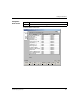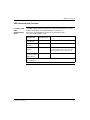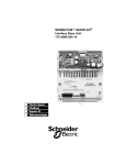
1
Modicon
XMIT Function Block
User Guide
31000685 02
31000685 02
840USE11300
Version 4.0
2
840USE11300 September 2003
Table of Contents
Safety Information . . . . . . . . . . . . . . . . . . . . . . . . . . . . . . . . . . . . 7
About the Book . . . . . . . . . . . . . . . . . . . . . . . . . . . . . . . . . . . . . . . 9
Chapter 1
Introduction to XMIT. . . . . . . . . . . . . . . . . . . . . . . . . . . . . . . . . . 11
At a Glance . . . . . . . . . . . . . . . . . . . . . . . . . . . . . . . . . . . . . . . . . . . . . . . . . . . . .
XMIT Specific Functionality . . . . . . . . . . . . . . . . . . . . . . . . . . . . . . . . . . . . . . . . .
Schneider Electric Products Supporting XMIT . . . . . . . . . . . . . . . . . . . . . . . . . .
XMIT Loadable Specifications. . . . . . . . . . . . . . . . . . . . . . . . . . . . . . . . . . . . . . .
PLC Loadable Functions . . . . . . . . . . . . . . . . . . . . . . . . . . . . . . . . . . . . . . . . . . .
XMIT Built-in Specifications. . . . . . . . . . . . . . . . . . . . . . . . . . . . . . . . . . . . . . . . .
Customer Service . . . . . . . . . . . . . . . . . . . . . . . . . . . . . . . . . . . . . . . . . . . . . . . .
Chapter 2
2.1
2.2
Chapter 3
Installing the XMIT Loadable Function Block . . . . . . . . . . . . . 21
At a Glance . . . . . . . . . . . . . . . . . . . . . . . . . . . . . . . . . . . . . . . . . . . . . . . . . . . . .
Installing the XMIT Loadable with Modsoft . . . . . . . . . . . . . . . . . . . . . . . . . . . . .
At a Glance . . . . . . . . . . . . . . . . . . . . . . . . . . . . . . . . . . . . . . . . . . . . . . . . . . . . .
Transferring the Loadable to a PLC and Selecting Options Using Modsoft . . . .
Loading Modsoft XMIT Zoom and Help Screens . . . . . . . . . . . . . . . . . . . . . . . .
Loading NSUP.EXE Using Modsoft . . . . . . . . . . . . . . . . . . . . . . . . . . . . . . . . . .
Loading XMIT.EXE Using Modsoft . . . . . . . . . . . . . . . . . . . . . . . . . . . . . . . . . . .
Installing the XMIT Loadable with Concept and ProWORX . . . . . . . . . . . . . . . .
At a Glance . . . . . . . . . . . . . . . . . . . . . . . . . . . . . . . . . . . . . . . . . . . . . . . . . . . . .
Loading the NSUP and XMIT Loadables Using Concept . . . . . . . . . . . . . . . . . .
Loading the NSUP and XMIT Loadables Using ProWORX NxT. . . . . . . . . . . . .
Loading the NSUP and XMIT Loadables Using ProWORX32 . . . . . . . . . . . . . .
21
22
22
23
25
26
28
30
30
31
34
39
Using Zoom Screens . . . . . . . . . . . . . . . . . . . . . . . . . . . . . . . . . 47
At a Glance . . . . . . . . . . . . . . . . . . . . . . . . . . . . . . . . . . . . . . . . . . . . . . . . . . . . .
Communication Block Zoom Screens Using Modsoft . . . . . . . . . . . . . . . . . . . . .
Port Status Block Zoom Screens Using Modsoft . . . . . . . . . . . . . . . . . . . . . . . .
Conversion Block Zoom Screens Using Modsoft . . . . . . . . . . . . . . . . . . . . . . . .
Zoom Screens Using Concept . . . . . . . . . . . . . . . . . . . . . . . . . . . . . . . . . . . . . .
Zoom Screens Using ProWORX NxT . . . . . . . . . . . . . . . . . . . . . . . . . . . . . . . . .
Zoom Screens Using ProWORX32 . . . . . . . . . . . . . . . . . . . . . . . . . . . . . . . . . . .
840USE11300 September 2003
11
12
14
16
18
19
20
47
48
52
54
56
60
63
3
Chapter 4
4.1
4.2
4.3
4.4
4.5
4.6
4
Using the XMIT Function Block . . . . . . . . . . . . . . . . . . . . . . . . 67
At a Glance . . . . . . . . . . . . . . . . . . . . . . . . . . . . . . . . . . . . . . . . . . . . . . . . . . . . . 67
Describing the XMIT Communication Block. . . . . . . . . . . . . . . . . . . . . . . . . . . . . 68
At a Glance . . . . . . . . . . . . . . . . . . . . . . . . . . . . . . . . . . . . . . . . . . . . . . . . . . . . . 68
XMIT and PLC Compatablility . . . . . . . . . . . . . . . . . . . . . . . . . . . . . . . . . . . . . . . 69
XMIT Function Block Structure . . . . . . . . . . . . . . . . . . . . . . . . . . . . . . . . . . . . . . 71
XMIT Node Contents . . . . . . . . . . . . . . . . . . . . . . . . . . . . . . . . . . . . . . . . . . . . . . 73
XMIT Communication Functions . . . . . . . . . . . . . . . . . . . . . . . . . . . . . . . . . . . . . 75
Using the XMIT Communication Block Registers . . . . . . . . . . . . . . . . . . . . . . . . 76
At a Glance . . . . . . . . . . . . . . . . . . . . . . . . . . . . . . . . . . . . . . . . . . . . . . . . . . . . . 76
XMIT Communication Block Registers 4x through 4x + 7 . . . . . . . . . . . . . . . . . . 77
XMIT Communication Block Register 4x + 8 . . . . . . . . . . . . . . . . . . . . . . . . . . . . 80
XMIT Communication Block Register 4x + 8, Bit 5 . . . . . . . . . . . . . . . . . . . . . . . 83
XMIT Communication Block Register 4x + 8, Bit 6 . . . . . . . . . . . . . . . . . . . . . . . 85
XMITCommunications Block Register 4x + 8, Bit 9 . . . . . . . . . . . . . . . . . . . . . . . 86
XMIT Communications Block Register 4x + 8, Bit 10 . . . . . . . . . . . . . . . . . . . . . 87
XMIT Communications Block Register 4x + 8, Bit 11 . . . . . . . . . . . . . . . . . . . . . 88
XMIT Communications Block Register 4x + 8, Bit 12 . . . . . . . . . . . . . . . . . . . . . 89
XMIT Communications Block Register 4x + 9,
Function Codes 01 through 06, 15, and 16 . . . . . . . . . . . . . . . . . . . . . . . . . . . . . 91
XMIT Communications Block Register 4x + 9, Function Code 8 . . . . . . . . . . . . . 93
XMIT Communications Block Register 4x + 9, Function Codes 20 and 21 . . . . . 95
XMIT Communications Block Registers 4x + 10 through 4x + 15 . . . . . . . . . . . . 97
Describing and Using the XMIT Port Status Block. . . . . . . . . . . . . . . . . . . . . . . . 98
At a Glance . . . . . . . . . . . . . . . . . . . . . . . . . . . . . . . . . . . . . . . . . . . . . . . . . . . . . 98
XMIT Port Status Block and PLC Compatability . . . . . . . . . . . . . . . . . . . . . . . . . 99
XMIT Port Status Function Block Representation and Node Contents . . . . . . . 101
XMIT Port Status Display Table. . . . . . . . . . . . . . . . . . . . . . . . . . . . . . . . . . . . . 103
Describing the XMIT Conversion Block . . . . . . . . . . . . . . . . . . . . . . . . . . . . . . . 106
At a Glance . . . . . . . . . . . . . . . . . . . . . . . . . . . . . . . . . . . . . . . . . . . . . . . . . . . . 106
XMIT Conversion Block and PLC Compatibility. . . . . . . . . . . . . . . . . . . . . . . . . 107
XMIT Conversion Block Structure and Contents . . . . . . . . . . . . . . . . . . . . . . . . 109
Using the XMIT Conversion Block . . . . . . . . . . . . . . . . . . . . . . . . . . . . . . . . . . . 111
At a Glance . . . . . . . . . . . . . . . . . . . . . . . . . . . . . . . . . . . . . . . . . . . . . . . . . . . . 111
XMIT Conversion Block Registers 4x through 4x + 2 . . . . . . . . . . . . . . . . . . . . 112
XMIT Conversion Block Register 4x + 3 . . . . . . . . . . . . . . . . . . . . . . . . . . . . . . 113
XMIT Conversion Block Registers 4x + 4 through 4x + 7 . . . . . . . . . . . . . . . . . 115
Working with XMIT Conversion Block Opcode Examples . . . . . . . . . . . . . . . . . 117
At a Glance . . . . . . . . . . . . . . . . . . . . . . . . . . . . . . . . . . . . . . . . . . . . . . . . . . . . 117
XMIT Conversion Opcode Examples 1 through 3 . . . . . . . . . . . . . . . . . . . . . . . 118
XMIT Conversion Block Opcode Examples 4 through 6 . . . . . . . . . . . . . . . . . . 122
XMIT Conversion Block Opcode Examples 7 through 11 . . . . . . . . . . . . . . . . . 124
XMIT Binary/BCD Conversion Types. . . . . . . . . . . . . . . . . . . . . . . . . . . . . . . . . 126
840USE11300 September 2003
Chapter 5
5.1
5.2
5.3
Appendices
Working with XMIT Examples . . . . . . . . . . . . . . . . . . . . . . . . . 127
At a Glance . . . . . . . . . . . . . . . . . . . . . . . . . . . . . . . . . . . . . . . . . . . . . . . . . . . .
Simple ASCII Reads/Writes and Modbus Reads/Writes . . . . . . . . . . . . . . . . . .
At a Glance . . . . . . . . . . . . . . . . . . . . . . . . . . . . . . . . . . . . . . . . . . . . . . . . . . . .
Simple ASCII Read of Characters Using Concept . . . . . . . . . . . . . . . . . . . . . .
Simple ASCII Write of Characters Using ProWORX32 . . . . . . . . . . . . . . . . . . .
Modbus Read Using ProWORX NxT . . . . . . . . . . . . . . . . . . . . . . . . . . . . . . . .
RS485 Port #2 Modbus Write Using ProWORX NxT . . . . . . . . . . . . . . . . . . . .
Transmitting Multiple Modbus Commands: PLC Master to PLC Slave . . . . . . .
At a Glance . . . . . . . . . . . . . . . . . . . . . . . . . . . . . . . . . . . . . . . . . . . . . . . . . . . .
Sending Multiple Modbus Commands. . . . . . . . . . . . . . . . . . . . . . . . . . . . . . . .
Setting up Master PLC . . . . . . . . . . . . . . . . . . . . . . . . . . . . . . . . . . . . . . . . . . .
Using Ladder Logic for Multiple Modbus Commands—Network #1 . . . . . . . . .
Using Ladder Logic for Multiple Modbus Commands—Network #2 . . . . . . . . .
Using Ladder Logic for Multiple Modbus Commands—Network #3 . . . . . . . . .
Using Ladder Logic for Multiple Modbus Commands—Network #4 . . . . . . . . .
Concluding Transmission of Multiple Modbus Commands . . . . . . . . . . . . . . . .
Transmitting the Fault Word to PLC Slave via Dial-up Modems . . . . . . . . . . . .
At a Glance . . . . . . . . . . . . . . . . . . . . . . . . . . . . . . . . . . . . . . . . . . . . . . . . . . . .
Fault Word Transmission to Slave PLC via Dialup Modems. . . . . . . . . . . . . . .
Modem Setup . . . . . . . . . . . . . . . . . . . . . . . . . . . . . . . . . . . . . . . . . . . . . . . . . .
Setting Up Master PLC . . . . . . . . . . . . . . . . . . . . . . . . . . . . . . . . . . . . . . . . . . .
Using Ladder Logic for Fault Word Transmission—Network #1 . . . . . . . . . . . .
Using Ladder Logic for Fault Word Transmission—Network #2 . . . . . . . . . . . .
Using Ladder Logic for Fault Word Transmission—Network #3 . . . . . . . . . . . .
Using Ladder Logic for Fault Word Transmission—Network #4 . . . . . . . . . . . .
Concluding Transmission of the Fault Word . . . . . . . . . . . . . . . . . . . . . . . . . . .
127
128
128
129
132
136
140
144
144
145
146
147
148
151
153
154
155
155
156
157
158
159
160
163
165
166
. . . . . . . . . . . . . . . . . . . . . . . . . . . . . . . . . . . . . . . . . . . . . 167
At a Glance . . . . . . . . . . . . . . . . . . . . . . . . . . . . . . . . . . . . . . . . . . . . . . . . . . . . 167
Appendix A
A.1
A.2
840USE11300 September 2003
XMIT Technical References . . . . . . . . . . . . . . . . . . . . . . . . . . 169
At a Glance . . . . . . . . . . . . . . . . . . . . . . . . . . . . . . . . . . . . . . . . . . . . . . . . . . . .
Working with Modbus Query/Response Parameters . . . . . . . . . . . . . . . . . . . .
Modbus Query/Response Parameter Limits . . . . . . . . . . . . . . . . . . . . . . . . . . .
Working with Cable Pinouts and Adapters . . . . . . . . . . . . . . . . . . . . . . . . . . . .
At a Glance . . . . . . . . . . . . . . . . . . . . . . . . . . . . . . . . . . . . . . . . . . . . . . . . . . . .
Cable Pinouts . . . . . . . . . . . . . . . . . . . . . . . . . . . . . . . . . . . . . . . . . . . . . . . . . .
9-Pin to 25-Pin (Modem) with NO RTS/CTS Control . . . . . . . . . . . . . . . . . . . .
9-Pin to 25-Pin (Modem) with RTS/CTS Control. . . . . . . . . . . . . . . . . . . . . . . .
9-Pin to 25-Pin (Null Modem) . . . . . . . . . . . . . . . . . . . . . . . . . . . . . . . . . . . . . .
9-Pin to 9-Pin (Modem) . . . . . . . . . . . . . . . . . . . . . . . . . . . . . . . . . . . . . . . . . . .
9-Pin to 9-Pin (Null Modem) . . . . . . . . . . . . . . . . . . . . . . . . . . . . . . . . . . . . . . .
RJ-45 (8x8) to 25-Pin Male (Modem) (Configuration A) . . . . . . . . . . . . . . . . . .
RJ-45 (8x8) to 25-Pin Male (Modem) (Configuration B) . . . . . . . . . . . . . . . . . .
169
170
170
173
173
174
175
176
177
178
179
180
181
5
A.3
Index
6
RJ-45-(8x8) to 25-Pin Male (Null Modem) . . . . . . . . . . . . . . . . . . . . . . . . . . . . . 182
RJ-45 (8x8) 9-Pin Male (Modem) (Configuration A) . . . . . . . . . . . . . . . . . . . . . 183
RJ-45 (8x8) 9-Pin Male (Modem) (Configuration B) . . . . . . . . . . . . . . . . . . . . . 184
RJ-45 (8x8) 9-Pin Male (Null Modem) . . . . . . . . . . . . . . . . . . . . . . . . . . . . . . . . 185
RJ-45 (8x8) to RJ-45 (8x8) (Modem) . . . . . . . . . . . . . . . . . . . . . . . . . . . . . . . . . 186
Cable Adapter Kits . . . . . . . . . . . . . . . . . . . . . . . . . . . . . . . . . . . . . . . . . . . . . . . 187
Configuring XMIT with Hayes Compatible Dial-up Modems (Only) . . . . . . . . . . 188
At a Glance . . . . . . . . . . . . . . . . . . . . . . . . . . . . . . . . . . . . . . . . . . . . . . . . . . . . 188
Using XMIT Configuration with Hayes Compatible Dial-up Modems (Only) . . . 189
Using Initialization Messages with Hayes Modems . . . . . . . . . . . . . . . . . . . . . . 190
Using Dial Modem Messages with Hayes Modems. . . . . . . . . . . . . . . . . . . . . . 192
Using Hang-up Messages with Hayes Compatible Dial-up Modems (Only) . . . 193
. . . . . . . . . . . . . . . . . . . . . . . . . . . . . . . . . . . . . . . . . . . . . . 195
840USE11300 September 2003
Safety Information
§
Important Information
NOTICE
Read these instructions carefully, and look at the equipment to become familiar with
the device before trying to install, operate, or maintain it. The following special
messages may appear throughout this documentation or on the equipment to warn
of potential hazards or to call attention to information that clarifies or simplifies a
procedure.
The addition of this symbol to a Danger or Warning safety label indicates
that an electrical hazard exists, which will result in personal injury if the
instructions are not followed.
This is the safety alert symbol. It is used to alert you to potential personal
injury hazards. Obey all safety messages that follow this symbol to avoid
possible injury or death.
DANGER
DANGER indicates an imminently hazardous situation, which, if not avoided, will
result in death, serious injury, or equipment damage.
WARNING
WARNING indicates a potentially hazardous situation, which, if not avoided, can result
in death, serious injury, or equipment damage.
CAUTION
CAUTION indicates a potentially hazardous situation, which, if not avoided, can result
in injury or equipment damage.
840USE11300 September 2003
7
Safety Information
PLEASE NOTE
8
Electrical equipment should be serviced only by qualified personnel. No responsibility is assumed by Schneider Electric for any consequences arising out of the use
of this material. This document is not intended as an instruction manual for untrained
persons.
© 2003 Schneider Electric. All Rights Reserved.
840USE11300 September 2003
About the Book
At a Glance
Document Scope
This user guide presents all information needed for both the loadable and the builtin versions of the (984LL) XMIT function block, which operates on all PLC hardware
platforms using the Modsoft, Concept (all versions), ProWORX NxT (all versions),
and ProWORX32 (all versions) panel software.
Note: This guide uses the phrase "panel software" to refer to either Modsoft,
Concept, ProWORX NxT, or ProWORX32.
Note: This user guide does NOT address the IEC XXMIT function block used with
Concept panel software.
Validity Note
840USE11300 September 2003
The data and illustrations found in this book are not binding. We reserve the right to
modify our products in line with our policy of continuous product development. The
information in this document is subject to change without notice and should not be
construed as a commitment by Schneider Electric.
9
About the Book
Related
Documents
Title of Documentation
Reference Number
Modicon Modbus Protocol Reference Guide
PI-MBUS-300
984-A120 Compact PLCs User Guide
890USE10800
Modicon Quantum Automation Series Hardware Reference Guide
840USE10000
Momentum M1 Processor Adapter and Option Adapter User Manual 870USE10110
Modicon 512/612 Micro PLC Hardware User Manual
890USE14500
Modicon Micro Controllers Ladder Logic Manual
890USE14600
Modicon Modsoft Programmer User Guide
890USE11500
Modicon Ladder Logic Block Library User Guide
840USE10100
Modicon 309COM4550x XMIT Loadable Read Me First Sheet
GI-XMIT-RMF
Product Related
Warnings
All pertinent state, regional, and local safety regulations must be observed when
installing and using this product. For reasons of safety and to assure compliance
with documented system data, repairs to components should be performed only by
the manufacturer.
Schneider Electric assumes no responsibility for any errors that may appear in this
document. If you have any suggestions for improvements or amendments or have
found errors in this publication, please notify us.
No part of this document may be reproduced in any form or by any means, electronic
or mechanical, including photocopying, without express written permission of
Schneider Electric.
User Comments
We welcome your comments about this document. You can reach us by e-mail at
[email protected]
10
840USE11300 September 2003
Introduction to XMIT
1
At a Glance
Introduction
This material presents information about the XMIT function block.
What’s in this
Chapter?
This chapter contains the following topics:
840USE11300 September 2003
Topic
Page
XMIT Specific Functionality
12
Schneider Electric Products Supporting XMIT
14
XMIT Loadable Specifications
16
PLC Loadable Functions
18
XMIT Built-in Specifications
19
Customer Service
20
11
Introduction to XMIT
XMIT Specific Functionality
XMIT Description
The transmit (XMIT) function block which is available either as a loadable exec or as
a built-in feature performs
l ASCII messaging
l simple ASCII
l terminated ASCII
l Modbus messaging
l port status information
l data conversion
XMIT Availability
XMIT function block is a loadable on
l Quantum
l Compact
l Micro
XMIT function block is built-in on
l Momentum
XMIT Modes
XMIT modes:
l Communication mode
l Port status mode
l Conversion mode
XMIT Inputs
12
Based upon the needs of your application, you may either (1) import and export
ASCII or binary data into your PLC or (2) convert data into various ASCII or binary
data to send to Data Communication Equipment (DCE) devices. See Using the
XMIT Communication Block Registers, p. 76 for details about the XMIT
communication block, Describing and Using the XMIT Port Status Block, p. 98 for
XMIT port status block, and Using the XMIT Conversion Block, p. 111 for XMIT
conversion block.
840USE11300 September 2003
Introduction to XMIT
XMIT
Diagnostics
The XMIT function block has built-in diagnostics that ensure no other XMIT blocks
are active in the PLC. Within the XMIT function block, a control table allows you to
control the communications link between the PLC and DCE devices attached to the
PLC’s Modbus port #1 or port #2. While transmitting data, the XMIT block does NOT
activate the port LED.
Note: Contention Resolution and Collision Avoidance
Modbus Protocol is a "one master/many slaves" protocol
Modbus requires using only one master that polls multiple slaves. Therefore, when
using the XMIT function block in a network with multiple masters, contention
resolution and collision avoidance is your responsibility. Contention resolution and
collision avoidance may be addressed easily through ladder logic programming.
XMIT and
Modbus
Messages
840USE11300 September 2003
The XMIT function block sends either (1) Modbus messages from a "master" PLC
to multiple "slave" PLCs or (2) ASCII character strings from the PLC's Modbus slave
port#1 or port#2 to ASCII printers and terminals. The XMIT function block sends
these messages over telephone dialup modems, radio modems, or direct
connection.
13
Introduction to XMIT
Schneider Electric Products Supporting XMIT
XMIT
Functionality
Restrictions
Schneider Electric products supporting XMIT function block
XMIT Function Block
Product Family
Controls Port #1 and/or #2 on Momentum
Model Numbers
171CCS70000
171CCS70010
171CCS76000
171CCC76010
171CCS78000
171CCC78010
Controls Port #1 on
Quantum
140CPU11302
140CPU11303
140CPU21304
140CPU42402
140CPU43412
140CPU53412
140CPU43412A
140CPU53414A
Compact
PC E984 2xx PLCs
984-E258
984-E265
984-E275
984-E285
Controls Port #2 on
Micro
110CPU61204
Momentum
171CCC98020
171CCC96020
171CCC98030
171CCC96030
171CCC98091
171CCC96091
14
840USE11300 September 2003
Introduction to XMIT
XMIT Function Block
Product Family
Does NOT Operate on
Micro
Model Numbers
110CPU512 xx
110CPU61200/03
Compact
PC A984 1xx
PC 0984 1xx
Limits exist for Modbus query/response parameters based upon the PLC model.
(See Modbus Query/Response Parameter Limits, p. 170.)
840USE11300 September 2003
15
Introduction to XMIT
XMIT Loadable Specifications
XMIT Loadable
Function Block
The following information applies to the XMIT loadable function block.
l Modsoft Version 2.5 or lower (Part Number SW MSxD 9SA)
l Modsoft Version 2.6 or higher (Part Number SW MSxD 9SA)
l XMIT Loadable Function Block (Part Number 309 COM 455 0x)
Includes four files and two sub-directories:
l README.TXT
l NSUP.EXE
l XMIT1968.HLP
l XMIT.EXE
l /MS_25
Contains the DXFDT.SYS file
l /MS_26
Contains the XMIT.ZMM file
16
840USE11300 September 2003
Introduction to XMIT
Non-PC
Executable
The loadable version of the XMIT block is available on the following models
Family
Model Number
Quantum
140CPU11302
140CPU21304
140CPU11303
(with 2.12 executive or higher)
140CPU42402
(with 2.10 executive or higher)
140CPU43412
140CPU53414
(with 1.02 executive or higher)
140CPU43412A
140CPU53414A
Compact
PC E984 241
PC E984 245
PC E984 251
PC E984 255
(with 1.02 executive or higher
984-E258
984-E265
984-E275
984-E285
Micro
Communication Media
110 CPU 612 04
(with 1.00 executive or higher)
Dialup type modems
Lease-line modems
For further information about communication media refer to the
list of tested modems and printers in
Modicon 309 COM 455 00 XMIT Loadable Read-Me-First
(GI-XMIT-RMF).
840USE11300 September 2003
17
Introduction to XMIT
PLC Loadable Functions
Overview of
Loadables
Within a PLC exist configuration data tables. Loadable function blocks, executable
software code programmed into the application, can be added to the controller/PLC.
These loadable functions
l are application-specific programmable blocks loaded into the PLC
l allow setting opcodes through panel software
l "configure" the loadable functions into the larger control program
The executable software code is programmed into the application in the format of a
standard three-node Ladder Logic instruction block. The basic logic subroutinestructure of a loadable is shown in the following graphic.
The logic flow of the loadable’s code
In a field environment, loadable functions can be added to existing control logic and
offer a software solution to specific application problems.
18
840USE11300 September 2003
Introduction to XMIT
XMIT Built-in Specifications
XMIT Built-in
Function Block
Required
l Modsoft Version 2.6 or higher (Part Number SW MSxD 9SA).
The built-in version of the XMIT block is available on the following models
Family
Model Number
Momentum
171CCS70000
171CCS70010
171CCS76000
171CCS78000
171CCC76010
171CCC78010
(with 2.00 executive or higher)
171CCC98020
171CCC96020
171CCC98030
171CCC96030
171CCC98091
171CCC96091
Momentum controllers support one stop bit only.
Communication Media
Dialup type modems
Lease-line modems
For further information about communication media, refer to
the list of tested modems and printers in
Modicon 309 COM 455 00 XMIT Loadable Read-Me-First
(GI-XMIT-RMF).
840USE11300 September 2003
19
Introduction to XMIT
Customer Service
Customer
Service Contact
Information
20
Schneider Automation telephone numbers are as follows:
l To call us from anywhere in North America—except from within the state of
Massachusetts:
(800) 468 5342
l To call us from within Massachusetts:
(978) 975 5001
l To call us from outside North America:
1 (978) 975 5001
l To fax us:
(978) 975 9301
840USE11300 September 2003
Installing the XMIT Loadable
Function Block
2
At a Glance
Overview
This chapter describes installing the XMIT Loadable Function Block and provides
important information about the files contained within the block.
Before loading, you should be familiar with panel software, have configured the PLC,
and are ready to load XMIT.
The graphics in this unit are examples of the screens that you see as you transfer
the XMIT Loadable from the disk to the 984 controller and use XMIT.
What’s in this
Chapter?
840USE11300 September 2003
This chapter contains the following sections:
Section
Topic
Page
2.1
Installing the XMIT Loadable with Modsoft
22
2.2
Installing the XMIT Loadable with Concept and ProWORX
30
21
Installing XMIT
2.1
Installing the XMIT Loadable with Modsoft
At a Glance
Purpose
This section describes installing the XMIT loadable function block using Modsoft and
provides important information about the files contained within the block.
Before loading, you should be familiar with Modsoft, have configured the PLC, and
are about to load XMIT.
The graphics in this section are examples of the screens that you see as you transfer
the XMIT Loadable from the disk to the 984 controller and use XMIT.
What’s in this
Section?
This section contains the following topics:
Topic
Page
Transferring the Loadable to a PLC and Selecting Options Using Modsoft
22
23
Loading Modsoft XMIT Zoom and Help Screens
25
Loading NSUP.EXE Using Modsoft
26
Loading XMIT.EXE Using Modsoft
28
840USE11300 September 2003
Installing XMIT
Transferring the Loadable to a PLC and Selecting Options Using Modsoft
Before Loading
You should be familiar with Modsoft, have configured the PLC, and are about to load
XMIT.
When you have concluded the transfer to the panel, the DX—with the
configuration—will be downloaded to the controller.
Transferring
XMIT from Disk
to 984 PLC
When the loadable is transferred to the panel, Modsoft converts XMIT.EXE to a DX
file named XMIT1968.EXE.
Step
1
About NSUP and
LSUP
Action
Insert the XMIT Loadable Function Block Disk
(Part Number 309 COM 455 0x) into disk drive A:
2
Select Offline (F2) on the Main Menu.
3
Select either Select Program or New Program from the menu.
4
Select Configuration (F5) from the menu.
Note: The NSUP and LSUP loadables are used to communicate the loadables
(.EXE files) to the PLC operating system.
l XMIT Loadable Function Block on the disk includes four files and two subdirectories:
l
l
l
l
l
README.TXT
NSUP.EXE
XMIT1968.HLP
XMIT.EXE
/MS_25
Contains the DXFDT.SYS file
l /MS_26
Contains the XMIT.ZMM file
840USE11300 September 2003
23
Installing XMIT
Selecting a
Segment and
Network
Selecting an
XMIT Loadable
Selecting Zoom
Screens
If you want to select a segment and a network, do the following.
Step
1
Press Escape (Esc) twice.
2
The Segment Status Display appears.
3
Select Element (F3).
4
Select a segment and a network.
5
Press Enter.
To select a specific XMIT loadable, do the following.
Step
Action
1
Select Loadable (F5).
2
From the list, select the needed XMIT loadable.
There are fourteen zoom screens for the XMIT block. (See Communication Block
Zoom Screens Using Modsoft, p. 48).
Step
1
24
Action
Action
Place your cursor on the XMIT block.
2
Press Alt + Z to display the XMIT zoom screens.
3
Select parameters in your zoom screens.
Select parameters appropriate for your application. The chapter, Using the XMIT
Function Block, p. 67, describes setting system parameters.
840USE11300 September 2003
Installing XMIT
Loading Modsoft XMIT Zoom and Help Screens
Loading DX
Zoom Screens:
DXFDT.SYS
When using Modsoft 2.5 (or lower) for DX zoom screens, load DXFDT.SYS.
Step
1
Loading DX
Zoom Screens:
XMIT.ZMM
840USE11300 September 2003
Before loading, please not the following.
Ensure that you are using Modsoft 2.5 (or lower) to use the DX zoom
screens loaded with DXFDT.SYS file.
l If you are NOT using Modsoft 2.5 (or lower), see Loading DX Zoom
Screens: XMIT.ZMM.
l
2
The DXFDT.SYS file is stored in the /MS_25 sub-directory.
3
Copy the DXFDT.SYS file to the Modsoft/runtime directory.
4
Note: The DXFDT.SYS file replaces the existing DXFDT.SYS file.
When using Modsoft 2.6 (or higher) for DX zoom screens, load XMIT.ZMM.
Step
1
Loading Help
Screens:
XMIT1968.HLP
Action
Action
Before loading,
Ensure that you are using Modsoft 2.6 (or higher) to use the DX zoom
screens loaded with the XMIT.ZMM file.
l If you are NOT using Modsoft 2.6 or higher, see Loading DX Zoom Screens:
DXFDT.SYS.
l
2
The XMIT.ZMM file is stored in the /MS_26 sub-directory.
3
Copy the XMIT.ZMM file to the directory in which the program files reside.
4
Note: AVAILABILITY OF DX ZOOM SCREENS
The XMIT.ZMM file MUST be in the same directory as the program files for the
program using XMIT, or the DX zoom screens will NOT be available.
Follow these steps.
Step
Action
1
Copy the XMIT1968.HLP file to the directory in which the program files reside.
2
Note: AVAILABILITY OF HELP SCREEN
This file MUST be in the same directory as the program files for the program
using XMIT, or the help screen will not be available.
3
Select Alt H to access the help screen for XMIT.
25
Installing XMIT
Loading NSUP.EXE Using Modsoft
Before Loading
Note:
l To run the XMIT block on the PLC, load either the NSUP.EXE file or the
LSUP.EXE file.
l If you loaded LSUP.EXE, you need not load NSUP.EXE.
l Loading order
You MUST load the NSUP.EXE file BEFORE loading the XMIT.EXE file into the
PLC.
If you load XMIT.EXE first, the XMIT instruction will not operate correctly, and the
result is that all three outputs turn on.
l To obtain the latest revisions to your NSUP.EXE loadable, contact Customer
Service.
Loading
NSUP.EXE
26
Follow these steps.
Step
Action
1
Select Loadable (F7).
2
Select Dir (F3).
3
Select Load (F1).
A prompt appears asking for the filename.
4
Type A:\ NSUP.EXE.
5
Press Enter.
A system message appears telling you that you can now access this loadable.
840USE11300 September 2003
Installing XMIT
Step
Action
6
Press Shift + ? to display all available loadables.
The NSUP.EXE Loadable appears in this list.
7
Place your cursor on NSUP.EXE.
8
Press Enter.
The screen displays the revision number, the file size, and the opcode of the
NSUP Loadable.
The loadable’s opcode is ff (Hex).
9
840USE11300 September 2003
Note: Ensure that this opcode does not conflict with any other opcodes that may
be in use.
If a conflict exists, select a new opcode from the available list.
27
Installing XMIT
Loading XMIT.EXE Using Modsoft
Before Loading
Note:
When the NSUP loadable is
1. NOT installed, or
2. Installed after the XMIT loadable, or
3. Installed in a Quantum PLC with an older executive than the executive specified
in the unit entitled PLC Compatibility, p. 69
All three outputs turn on regardless of the input states.
Note: The NSUP.EXE file MUST be loaded into the PLC—BEFORE—the XMIT.EXE
file. If not, the XMIT instruction will not operate.
Loading
XMIT.EXE
28
Follow these steps.
Step
Action
1
Select Loadable (F7).
2
Select Dir (F3).
3
Select Load (F1).
A prompt appears asking for the filename.
4
Type A:\ XMIT.EXE.
5
Press Enter.
A system message appears telling you that you can now access the XMIT
loadable.
6
Move cursor below the name of the previous loadable to an open spot.
840USE11300 September 2003
Installing XMIT
Step
Action
7
Press Shift + ? to display all available loadables.
The XMIT Loadable should now appear in this list.
8
Place your cursor on XMIT and press Enter.
The screen displays the revision, the size, and the opcode of the XMIT Loadable.
The XMIT opcode is 1e (Hex).
Note:
l
l
840USE11300 September 2003
Ensure that this opcode does not conflict with any other opcodes that may be
in use.
The opcode shown on the screen may vary.
29
Installing XMIT
2.2
Installing the XMIT Loadable with Concept and
ProWORX
At a Glance
Purpose
This section describes installing the XMIT loadable function block using either the
Concept or ProWORX panel software.
Before loading, you should be familiar with either Concept or ProWORX depending
on which application you are using.
The graphics in this section are examples of the screens that you see as you transfer
the XMIT loadable.
What’s in this
Section?
This section contains the following topics:
30
Topic
Page
Loading the NSUP and XMIT Loadables Using Concept
31
Loading the NSUP and XMIT Loadables Using ProWORX NxT
34
Loading the NSUP and XMIT Loadables Using ProWORX32
39
840USE11300 September 2003
Installing XMIT
Loading the NSUP and XMIT Loadables Using Concept
Before Loading
Note: Loading Order
Install
1. NSUP.EXE
2. XMIT.EXE
Loading in an improper order, causes XMIT to not function.
Loading
NSUP.EXE
From the main ladder logic window in Concept, click on the Project drop down menu.
Step
1
Action
Select the Configurator.
The PLC Configuration dialog appears.
PLC Configuration
Summary
PLC Selection
PLC Memory Partition
Loadables
Specials
Config Extensions
I/O Map
Segment Scheduler
Modbus Port Settings
ASCII
2
140 CP
Disabl
PLC Memory Par
Coils:
Discrete Inputs:
Input Registers:
Holding Registe
Specials
Battery Coil:
In the Loadables area, double click next to "Number Installed:".
Available Logic Area:
Edit loadables
Loadables
Number installed:
840USE11300 September 2003
PLC
Type:
IEC
65535
0
31
Installing XMIT
Step
3
Action
After the Loadables dialog appears, click Unpack.
Loadables
Bytes Available:
Available:
@1S7
@1SE
@2I7
@2IE
ASUP
655360
Bytes Used: 0
Installed:
V196
V196
V196
V196
V196
Install =>
<= Remove
Unpack...
Warning!
Confirm user loadables are valid for your PLC
OK
Cancel
Edit...
Edit...
Help
4
Click OK.
5
When the Unpack Loadable File dialog appears, select NSUP.EXE.
Unpack Loadable File
File name:
XMIT.EXE
NSUP.EXE
XMIT.EXE
XMIT.EXE
List files of type:
User Loadables (*.exe)
Loading
XMIT.EXE
OK
a:\201
Cancel
a:\
201
Network...
List files of type:
a:
6
Click OK.
7
NSUP will now appear in the available loadables box.
To unpack the XMIT.EXE,
Step
1
32
Folders:
Action
Follow the same procedure as unpacking the NSUP.EXE.
840USE11300 September 2003
Installing XMIT
Installing the
Loadables
After loading NSUP.EXE, the loadables can now be installed to the database by
selecting the loadable. Then
Step
1
Action
Click Install =>.
Loadables
Bytes Available:
Available:
@1S7
@1SE
@2I7
@2IE
ASUP
655360
Bytes Used: 0
Installed:
V196
V196
V196
V196
V196
Install =>
<= Remove
Unpack...
Warning!
Confirm user loadables are valid for your PLC
OK
Cancel
2
Open the 984 LL Editor.
3
Open the Instruction Selection dialog.
Edit...
Edit...
Help
Instruction Selection
Group
Counters/Timers
Math
Move
Matrix
Special
Skips/Specials
Miscellaneous
ASCII Functions
Fast I/O Instructions
Loadable DX
Close
840USE11300 September 2003
Element
XMIT
Help on Instruction
Help
4
Loadable DX appears in the Group list, and XMIT appears in the Element list.
5
Click Close.
33
Installing XMIT
Loading the NSUP and XMIT Loadables Using ProWORX NxT
Before Loading
Note: Loading Order
Install
1. NSUP.EXE
2. XMIT.EXE
Loading in an improper order, causes XMIT to not function.
34
840USE11300 September 2003
Installing XMIT
Selecting
NSUP.EXE
From the main ladder logic window in Proworx Nxt click on the configuration dropdown menu.
Step
1
Action
Select the option configuration.
The Controller Configuration dialog appears.
Controller Configuration
General
Ports
Controller
User Loadables
0xxxx: 06000
Total Messages: 0000
1xxxx: 02048
Message Words: 00000
3xxxx: 00999
4xxxx: 09000
ASCII Ports: 00
Loadable Library
Battery Coil (0x): 06000
Timer Register (4x): 02048
Time of Day Clock (4x): 00999
Watch Dog Tm(*10ms): 09000
Conf Extension Size: 01
Segments: 01
Conf Ext Used: 00000
Enable Skips
I/O Words: 00512
I/O Time Slice: 020
OK
Cancel
Help
2
Click the loadable library tab.
3
Select Exe format.
User Loadables
Loadable Library
Source of Loadables
C:\NXT21\
Database
Old Taylor .TLD
Modicon
Exe format
Name
840USE11300 September 2003
4
Click Browse.
5
The Open dialog appears.
Opcode
35
Installing XMIT
Transferring
NSUP.EXE
After the Open dialog appears,
Step
Action
1 Select NSUP.EXE.
Open
Folders:
a:\201
File name:
nsup.exe
nsup.exe
xmit.exe
a:\
201
List files of type:
Lib file (*.exe)
OK
Cancel
Network...
Drives:
a:
2 NSUP and its Opcode displays in the Source of Loadables list.
ntroller
User Loadables
Loadable Library
Source of Loadables
A:\201\
Database Old Taylor .TLD
Modicon
Exe format
Name Opcode
NSUP (FF)
<<Transfer
Browse
Folders:
a:\201
a:\
201
OK
Cancel
Network...
3 Click <<Transfer.
4 NSUP will move from the Source of Loadables list to the Loadable Library | Library
Type list.
5 The Open dialog appears.
In the List Files of type: drop-down combo box, overwrite the phrase "proworx.?sl"
with the word "XMIT."
6 Click OK.
36
840USE11300 September 2003
Installing XMIT
Loading
NSUP.EXE into
the Database
In the Controller Configuration dialog, select the User Loadables tab.
Step
1
Action
In the loadable Library list, select the NSUP file (MSL NSUP (FF).
Controller Configuration
General
Ports
Controller
Loadable Library
A:\201\
Library Type:
Type
MSL
MSL
Name
NSUP
XMIT
Opcode
(FF)
(1F)
Load
Select Library...
OK
2
Loading
XMIT.EXE
Click Load>>.
3
NSUP and its OP code transfers to the Loadables in Database list.
4
Click OK.
Clicking OK returns you to the Ladder Logic screen.
To load XMIT.EXE,
Step
1
840USE11300 September 2003
Cancel
Action
Follow the same procedure as loading NSUP.EXE.
37
Installing XMIT
Finishing Up
At the end of the loading NSUP.EXE and XMIT.EXE process,
Step
Action
1
Check that both NSUP.EXE (NSUP (FF)) and XMIT.EXE (XMIT (1F)) appear in
the Loadables in Database list.
Controller
User Loadables
Loadable Library
Loadables in Database
C:\NXT21\
Name
NSUP
XMIT
Opcode
(FF)
(1F)
Load >>
Delete
Select All
Help
38
840USE11300 September 2003
Installing XMIT
Loading the NSUP and XMIT Loadables Using ProWORX32
Before Loading
Note: Loading Order
Install
1. NSUP.EXE
2. XMIT.EXE
Loading in an improper order, causes XMIT to not function.
Opening the
Wizard
On the ProWORX32 navigation pane, select the Utilities tab, and
Step
1
Action
Double click on the Loadable Library option.
Utilities
MBP Stat
BootP
Ping
Network Explorer
BM85 Configuration
Compare
I/O Drawing Viewer
Loadable Library
Exec Loader
Projects
2
840USE11300 September 2003
Utilities
The Loadable Library Wizard appears.
39
Installing XMIT
Selecting and
Transferring
NSUP.EXE Using
the Wizard
When the wizard opens,
Step Action
1
Select both the ‘Transfer Loadable into the loadable library’ and the ‘EXE loadable’
options.
Loadable Library Wizard
Select a loadable or loada
Edit opcode
View text
Rebuild library
Transfer loadable into loadable library
Select source of loadables:
Existing Project
Schneider loadable
Old Taylor TLD
EXE loadable
Help
2
Cancel
Click Browse... .
Browse...
Select All
All
Cancel
40
< Back
Next >
3
NSUP appears in the Path: list
4
Select NSUP.
Finish
Finish
840USE11300 September 2003
Installing XMIT
Loading
NSUP.EXE into
the Database
When the Open dialog appears,
Step
1
Action
Select NSUP loadable first.
Open
Look in:
201
NSUP
XMIT
History
Desktop
My Computer
My Network...
2
840USE11300 September 2003
File name:
NSUP
Files of type:
Lib file (*.exe)
Open
Cancel
Click Open.
The Loadable Library Wizard - Select Loadable displays.
41
Installing XMIT
Step
3
Action
NSUP and its Opcode (FF) display in the Path: list
Loadable Library Wizard - Select Loadable
Click Browse to select the loadab
Click Next to transfer the loadabl
library.
Source of Loadables: EXE loadable
Path:
A:\201\
Name
NSUP
Help
4
42
Opcode
(FF)
Cancel
< Back
Click Next.
840USE11300 September 2003
Installing XMIT
Selecting the
Library Type
When the Loadable Library Wizard - Select Library Type dialog appears,
Step
1
Action
Select Quantum
Loadable Library Wizard - Select Librar
Select the lo
unsure whi
for Quantu
984X, an
The x80
Quantum
Help
840USE11300 September 2003
2
Click Next.
3
Click Finish.
43
Installing XMIT
Configuring the
Controller
Return to the ProWORX32 navigation panel.
Step
1
Action
Select the Projects tap
My Computer
Nxt_demo
Greg <Offline>
Configuration
Traffic Cop
Communications
Logic
Data Editors
Configuration Extensions
ACII Messages
PLC Status
Analyze Device
Knowledge Base
Automation
Internet
Projects
2
44
Utilities
Click the Configuration option.
840USE11300 September 2003
Installing XMIT
Step
3
Action
In the Configuration dialog, select the Loadables tab.
Configuration [AS]
General
Ports
Controller Properties
Ranges
0xxxx
1xxxx
3xxxx
4xxxx
Segments
I/O Words
I/O Time Slice
Controller Properties
Duplicate Coil Start
Controller Type Quantum 534
ASCII
Modules
00
Total Messages
Total Extended...98304
Message Words
Total Logic
63226
ASCII Ports
Specials
Loadables
06000
02048
00999
09000
32
00512
020
00000
000
0000
00
Apply
Apply
4
Select the NSUP check box.
Configuration [AS]
General
Name
NSUP
Ports
Opcode
FF
Loadables
Version
196
Type
MSL
Apply
Apply
5
Loading
XMIT.EXE
To load XMIT.EXE,
Step
1
840USE11300 September 2003
Click Apply.
Action
Follow the same procedure as loading NSUP.EXE.
45
Installing XMIT
46
840USE11300 September 2003
Using Zoom Screens
3
At a Glance
Purpose
This chapter describes using Zoom screens with Modsoft, ProWORX NxT, and
ProWORX32. Zoom screens are not available in Concept. Use zoom screens to
configure the parameters of either the loadable or built-in XMIT block. Also, use the
zoom screens to configure the registers of the communication, port status, or
conversion blocks.
What’s in this
Chapter?
This chapter contains the following topics:
840USE11300 September 2003
Topic
Page
Communication Block Zoom Screens Using Modsoft
48
Port Status Block Zoom Screens Using Modsoft
52
Conversion Block Zoom Screens Using Modsoft
54
Zoom Screens Using Concept
56
Zoom Screens Using ProWORX NxT
60
Zoom Screens Using ProWORX32
63
47
Using Zoom Screens
Communication Block Zoom Screens Using Modsoft
Overview
This unit describes the Modsoft DX zoom screens associated with the
communication block of the XMIT function block. In the communication mode, eight
(8) zoom screens are available for configuring the parameters in registers 4x
through 4x + 15 and for displaying ASCII input information, pointer offset
information, and error status information.
Communication
Zoom Screens
(Eight)
Communication DX zoom screen, Page 1/8, used for configuring registers 4x
through 4x+8.
Communication DX zoom screen, Page 2/8, used for configuring the 4x+9 register
(Message Pointer).
48
840USE11300 September 2003
Using Zoom Screens
Communication DX zoom screen, Page 3/8, used to display ASCII input information
when 4x+9 is offset to the ASCII input definition table.
Communication DX zoom screen, Page 4/8, used for (a) displaying Diagnostic Code
Definitions and (b) configuring registers 4x+10 through 4x+15.
840USE11300 September 2003
49
Using Zoom Screens
Communication DX zoom screen, Page 5/8, displaying XMIT communication error
status (Fault Codes 1-8 and 100-105).
Communication DX zoom screen, Page 6/8, displaying XMIT communication error
messages (Fault Codes 106-118).
50
840USE11300 September 2003
Using Zoom Screens
Communication DX zoom screen, Page 7/8, displaying XMIT communication error
status (Fault Codes 119-131).
Communication DX zoom screen, Page 8/8, displaying XMIT communication error
status (Fault Codes 132-143).
840USE11300 September 2003
51
Using Zoom Screens
Port Status Block Zoom Screens Using Modsoft
Port Status Zoom
Screens (Three)
Port status DX zoom screen, page 1/3, used for configuring Get Status.
Port status DX zoom screen, Page 2/3, displaying XMIT port status error messages
(Fault Codes 119-131).
52
840USE11300 September 2003
Using Zoom Screens
Port status DX zoom screen, Page 3/3, displaying XMIT port status error messages
(Fault Codes 132-143).
840USE11300 September 2003
53
Using Zoom Screens
Conversion Block Zoom Screens Using Modsoft
Overview
This unit describes the Modsoft DX zoom screens associated with the conversion
block of the XMIT function block. In the conversion mode, three (3) zoom screens
are available for configuring and for displaying error status information.
Conversion
Zoom Screens
(Three)
Conversion DX zoom screen, page 1/3, used for configuring Conversions.
Conversion DX zoom screen, Page 2/3, displaying XMIT conversion error
messages (Fault Codes 119-131).
54
840USE11300 September 2003
Using Zoom Screens
Conversion DX zoom screen, Page 3/3, displaying XMIT conversion error
messages (Fault Codes 132-143).
840USE11300 September 2003
55
Using Zoom Screens
Zoom Screens Using Concept
Overview
This unit describes using zoom screens with the Concept panel software to
configure parameters and registers.
Accessing the
Zoom Screens in
Concept
From the Ladder Logic screen,
Step
Action
1
Place a XMIT block in the logic area.
2
Valid entries must be entered into the top, middle, and bottom nodes. For example,
enter #0001 in the top, 400001in the middle, and #00016 in the bottom.
3
Place your cursor over the XMIT block.
4
Press CTRL + D.
Page 1/8 of the XMIT: Communication dialog box appears
XMIT: Communication
Page:
1
4x
XMIT Revision Number
400101
UINT
201
DEC
4x + 1
Fault Status
400102
UINT
0
DEC
4x + 2
Available to User
400103
UINT
0
HEX
4x + 3
Data Rate
400104
UINT
9600
DEC
4x + 4
Data Bits (7, 8)
400105
UINT
8
DEC
4x + 5
Parity (0=none, 1=odd, 2=even)
400106
UINT
2
DEC
4x + 6
Stop Bits (1, 2)
400107
UINT
1
DEC
4x + 7
Available to User
400108
UINT
0
HEX
4x + 8
Command Word
400109
UINT
256
/8
Command Word Settings
RS485 Mode
RTS/CTS Modem Control
Simple Asc Input
Terminated Asc Input
4 Modbus Messaging
ASCII String Messaging
Asc Recv FIFO
Backspace
RTS/CTS Flow Control
Pulse Dial Modem ATDP
Xon/Xoff Flow Control
Hang-up Modem ATH
Tone Dial Modem ATDT
Initialize Modem AT
Close
56
<<
>>
Help
5
Type needed parameters.
6
Click the unfold button (>>) to access pages 2 through 8, or Click Close.
840USE11300 September 2003
Using Zoom Screens
Toggling
through the
Zoom Screens
Eight (8) zoom screens are available. Pages 1 through 4 are configuration screens.
Pages 5 through 8 are fault status screens.
Step Action
1
Select the next or previous unfold buttons (<< >>) to toggle between the eight screens.
XMIT Communication zoom screen 2/8
XMIT: Communication
Port:
Page:
#1
4x + 9
Message Pointer
400110
2
17
/8
DEC
Function 01-06, 15, 16
Modbus Function 08
Modbus Functions 20, 21
4y
4y
4y
4y + 1
4y + 2
4y + 3
4y + 4
Function Code
Quantity
Slave PLC Addr.
Slave Data Area
Master Data Area
4y + 1
4y + 2
4y + 3
4y + 4
Function Code
Subfunction Code
Slave PLC Addr.
Diag. Function Data
Master Data Area
4y + 1
4y + 2
4y + 3
4y + 4
4y + 5
Function Code
Quantity
Slave PLC Addr.
Slave Data Area
Master Data Area
File Number
Modbus Function Code Definitions
01
Read Coil Status
02
Read Input Status
03
Read Holding Registers
04
Read Input Registers
05
Force Single Cell
06
Preset Single Register
08
Diagnostics
15
Force Multiple Calls
16
Preset Multiple Registers
20
Read General Reference (6x)
21
Write General Reference (6x)
Close
840USE11300 September 2003
<<
>>
Help
57
Using Zoom Screens
XMIT: Communication zoom screen 3/8
XMIT: Communication
Port:
Page:
#1
3
Ascii Message Pointer
400110
UINT
17
DEC
Ascii Message Length
400111
UINT
5
DEC
/8
Info
When activated, message pointer reg 4x + 9 must register offset to the start
of Ascii input definition table. The table always has 5 words and the message
length register 4x + 10 must contain a length of 5.
The internal format of the Ascii input table is as follows.
Word 0:
High Byte = # of starting chars, Low Byte = # of terminator chars
Word 1:
High Byte = first starting char, Low Byte = second starting char
Word 2:
High Byte = first terminator char, Low Byte = second terminator char
Word 3:
Input storage destination register offset (e.g. 123 = 40123)
Word 4:
Number of received chars written into input storage destination
registers given by word 3
Close
58
<<
>>
Help
840USE11300 September 2003
Using Zoom Screens
XMIT: Communication zoom screen 4/8
XMIT: Communication
Port:
Page:
#1
4
/8
4x + 10
Message Length
400111
UINT
5
DEC
4x + 11
Response Time-Out (ms)
400112
UINT
1000
DEC
4x + 12
Retry Limit
400113
UINT
5
DEC
4x + 13
Start of Transmission Delay (ms)
400114
UINT
100
DEC
4x + 14
End of Transmission Delay (ms)
400115
UINT
100
DEC
4x + 15
Current Retry
400116
UINT
0
DEC
Diagnostic Code Functions
00 Return Query
11 Return Bus Message Count
01 Restart Comm Option
12 Return Bus Comm. Error Count
02 Return Diagnostic Register
13 Return Bus Exception Count
03 Change ASCII Input Delimeter
16 Return Slave NAK Count
04 Force Listen Only Mode
17 Return Slave Busy Count
10 Clear Registers
18 Return Bus Char. Overrun Count
Close
840USE11300 September 2003
<<
>>
Help
59
Using Zoom Screens
Zoom Screens Using ProWORX NxT
Accessing the
Zoom Screens in
ProWORX NxT
From the Ladder Logic screen,
Step
Action
1
Place a XMIT block in the logic area.
2
The Instruction Edit dialog appears.
3
Valid entries must be entered into the top, middle, and bottom nodes. For
example, enter #0001 in the top, 400001in the middle, and #00016 in the bottom.
4
Click OK.
5
Place your cursor over the XMIT block.
??????
??????
Instruction Edit
Top
#00001
Middle
400001
Cancel
XMIT
Function
Bottom
OK
#:00016
Used...
XMIT
??????
Valid Address Types:
Doc Editor...
#00001-#09999
Summary...
Inst. Help
Display for new instructions
6
60
Help
Press CTRL + R, and the zoom screens appear.
840USE11300 September 2003
Using Zoom Screens
Toggling
through the
Zoom Screens
Three (3) zoom screens are available.
Step
Action
1
Select the Prev or Next buttons to toggle between the three screens.
Communications zoom screen
XMIT: COMMUNICATIONS Page 1 of 3
AR:
Operation: Invalid operation type
#00001
400001
XMIT
#00016
Description
XMIT Revision Number
Fault Status
Available to User
Data Rate
Data Bits (7 or 8)
Parity (0=none, 1=odd
Stop Bits (1 or 2)
Available to User
Command Word
Message Pointer
Length of Message
Response Time-out (ms)
Retry Limit
Start of XMIT Delay (ms)
End of XMIT Delay (ms)
Current Retry
Address/Symbol
400001
400002
400003
400004
400005
400006
400007
400008
400009
400010
400011
400012
400013
400014
400015
400016
Data
00000 Dec
00000 Dec
00000 Dec
00000 Dec
00000 Dec
00000 Dec
00000 Dec
00000 Dec
00000000-00000000
00000 Dec
00000 Dec
00000 Dec
00000 Dec
00000 Dec
00000 Dec
00000 Dec
Error:
400001
Close
840USE11300 September 2003
Prev
Edit...
Doc...
Bits...
Operation...
Radix...
Print
Next
Help
61
Using Zoom Screens
Get Status zoom screen
XMIT: GET STATUS Page 2 of 3
Operation: Invalid operation type
#00001
400001
XMIT
#00016
Description
XMIT Revision Number
Fault Status
Slave Logged In/Active
Slave Transaction
Address/Symbol
400001
400002
400003
400004
AR:
Data
00000 Dec
00000 Dec
00000000-00000000
00000 Dec
Conversions zoom screen
XMIT: CONVERSIONS Page 3 of 3
Operation: Invalid operation type
#00001
400001
XMIT
#00016
62
Description
XMIT Revision Number
Fault Status
Available to User
Data Conversion Bits
Data Conversion Opcode
Source Register Offset
Destination Register
Ascii String Character
Address/Symbol
400001
400002
400003
400004
400005
400006
400007
400008
AR:
Data
00000 Dec
00000 Dec
00000 Dec
00000000-00000000
00000 Hex
00000 Dec
00000 Dec
00000 Dec
840USE11300 September 2003
Using Zoom Screens
Zoom Screens Using ProWORX32
Accessing the
Zoom Screens
Using
ProWORX32
From the Ladder Logic screen,
Step
Action
1
Place a XMIT block in the logic area.
2
Right click on the XMIT block.
3
Select Data | Register Editor.
#0001
Insert
Delete
4000
Edit
View
Search
XMIT
#0016
Data
Enable
Print Network
Update Cross References
Disable On
Rebuild Coil Used
Disable Off
Add Watch
Initialize Project Logic
Track
Ctrl+W
Register Editor
840USE11300 September 2003
63
Using Zoom Screens
Toggling
through the
Zoom Screens
Three (3) zoom screens are available.
Step
1
Action
When Register Editor is selected, the Communications zoom screen displays.
Instruction
XMIT
#0001
40001
#0016
2
64
COMMUNICATIONS
Description
Address
XMIT Revision Number
40001
Fault Status
40002
Available to User
40003
Data Rate
40004
Data Bits (7 or 8)
40005
Parity (0=None, 1-Odd, 2=Even)
40006
Current Page
Stop Bits (1 or 2)
40007
1/3
Available to User
40008
Command Word
40009
Message Pointer
40010
Length of Message
40011
Response Timeout (ms)
40012
Retry Limit
40013
Start of XMIT Delay (ms)
40014
End of XMIT Delay (ms)
40015
Current Retry
40016
Click the right or left arrows of the Current Page field to toggle through the
screens.
The Port Status and Conversion zoom screens are not displayed in this section.
840USE11300 September 2003
Using Zoom Screens
Accessing Bit
Display and Data
The individual bits of some registers like ‘Command Word’ enable or disable
functionality. View bit status using the Bit Display dialog.
Step
1
Action
To access the Bit Display dialog, select the elipsis button in the Data column.
Data
201
0
0
9600
8
2
1
0
00000001-00000000
17
5
1000
5
100
100
0
2
The Bit Display dialog appears.
Bit Display
OK
Command Word - 40009
MSB
Binary
Cancel
LSB
Hex
0100
Decimal
00256
Initialize Modem (AT)
Tone Dial Modem (ATDT)
Hang Up Modem (ATH)
Pulse Dial Modem (ATDP)
Xon/Xoff Flow Control
RTS/CTS Flow Control
Backspace
ASCII Receive FIFO
Enable Modbus Messaging
Enable ASCII String Messaging
Simple ASCII Input
Terminated ASCII Input
RS 485 Mode
Enable RTS/CTS Control
840USE11300 September 2003
65
Using Zoom Screens
66
840USE11300 September 2003
Using the XMIT Function Block
4
At a Glance
Introduction
This material presents information about the XMIT Communication Block.
What’s in this
Chapter?
This chapter contains the following sections:
840USE11300 September 2003
Section
Topic
Page
4.1
Describing the XMIT Communication Block
68
4.2
Using the XMIT Communication Block Registers
76
4.3
Describing and Using the XMIT Port Status Block
4.4
Describing the XMIT Conversion Block
106
4.5
Using the XMIT Conversion Block
111
4.6
Working with XMIT Conversion Block Opcode Examples
117
98
67
XMIT Function Block
4.1
Describing the XMIT Communication Block
At a Glance
Purpose
This section describes the XMIT communication block’s compatibility with Schneider
Electric products and provides information about XMIT functions.
What’s in this
Section?
This section contains the following topics:
68
Topic
Page
XMIT and PLC Compatablility
69
XMIT Function Block Structure
71
XMIT Node Contents
73
XMIT Communication Functions
75
840USE11300 September 2003
XMIT Function Block
XMIT and PLC Compatablility
PLC
Compatibility
The XMIT function block is compatible with the following Schneider Electric PLCs.
Product Family
Model Numbers
Quantum PLCs
140CPU11302
140CPU21304
140CPU11303
(with 2.12 executive or higher)
140CPU42402
(with 2.10 executive or higher)
140CPU43412
140CPU53414
(with 1.02 executive or higher)
140CPU43412A
140CPU53514A
Compact PLCs
PC E984 241
PC E984 245
PC E984 251
PC E984 255
(with 1.02 executive or higher)
984-E285
984-E265
984-E275
984-285
Micro PLCs
840USE11300 September 2003
110CPU61204
(with 1.00 executive or higher)
69
XMIT Function Block
Product Family
Momentum PLCs
Model Numbers
171CCS70000
171CCS70010
171CCS76000
171CCS78000
171CCC76010
171CCC78010
(with 2.00 executive or higher)
171CCC98020
171CCC96020
171CCC98030
171CCC96030
171CCC98091
171CCC96091
Momentum controllers support one stop bit only.
70
840USE11300 September 2003
XMIT Function Block
XMIT Function Block Structure
Representation
The XMIT Communication Block is three nodes high.
Inputs
XMIT has two possible control inputs.
The input to the top node begins an XMIT operation and it should remain ON until
either the operation has completed successfully or an error has occurred.
The input to the middle node aborts any active XMIT operation and forces the port
to slave mode. An abort code (121) is placed into the fault status register. The port
remains closed as long as this input is ON.
Note: To reset an XMIT fault and clear the fault register, the top input must go OFF
for at least one PLC scan.
840USE11300 September 2003
71
XMIT Function Block
Outputs
XMIT may produce three possible outputs.
The outputs from the top node goes ON while an XMIT operation is in progress.
The output from the middle node goes ON when XMIT has detected an error or was
issued an abort.
The output from the bottom node goes ON when an XMIT operation has been
successfully completed.
The following two notes apply to LOADABLES ONLY.
Note: OUTPUTS TURN ON
All three outputs turn on regardless of the input states if the NSUP loadable is
l NOT installed
l Installed AFTER the XMIT loadable
l Installed in a Quantum PLC with an older executive than specified in
(See PLC Compatibility, p. 69)
Note: LOAD NSUP.EXE BEFORE XMIT.EXE
The NSUP.EXE file MUST be loaded into the PLC BEFORE the XMIT.EXE file. If
not the XMIT instruction will not operate correctly and all three outputs turn on.
72
840USE11300 September 2003
XMIT Function Block
XMIT Node Contents
Top Node
Content
The top node must contain one of the two following constants either
l (#0001) to select PLC port #1
l (#0002) to select PLC port #2
IMPORTANT:
l LOADABLE ACCEPTS 4x registers in the top node.
l BUILT-IN does NOT ACCEPT 4x registers in the top node.
Middle Node
Content
The 4x register entered in the middle node is the first in a group of sixteen (16)
contiguous holding registers that comprise the control block, as shown in the
following table.
XMIT Communication Control Table Description.
Register
840USE11300 September 2003
Description
Valid Entries
4x
XMIT Revision Number
Read Only
4x +1
Fault Status
Read Only
4x +2
Available to User
0
May be used as pointers for instructions like
TBLK
4x +3
Data Rate
50, 75, 110, 134, 150, 300, 600, 1200,
2400, 9600, and 19200
4x +4
Data Bits
7,8
4x +5
Parity
0, 1, 2
4x +6
Stop Bits
0, 1, 2
4x +7
Available to User
0
May be used as pointers for instructions like
TBLK
4x +8
Command Word
0000-0000-0000-0000
4x +9
Pointer to Message Table
Limited by the range of 4x registers
configured
4x +10
Length of Message
0 ... 1024 (For ASCII messages)
For Modbus messages, see Modbus
Query/Response Parameter Limits, p. 170.
4x +11
Response Time-Out (mS)
0 ... 65535
4x +12
Retry Limit
0 ... 65535
4x +13
Start of Transmission Delay (mS)
0 ... 65535
4x +14
End of Transmission Delay (mS)
0 ... 65535
4x +15
Current Retry
Read Only
73
XMIT Function Block
Note: DO NOT MODIFY ADDRESS
Do NOT modify or delete the address in the middle node while the program is
active. Modifying or deleting locks up the port, which prevents communications.
Bottom Node
Content
74
The bottom node must contain a constant equal to (#0016). This constant is the
number of registers used by the XMIT instruction.
840USE11300 September 2003
XMIT Function Block
XMIT Communication Functions
Functions of the
XMIT
Communication
Block
The XMIT communication block performs the functions shown below. For each
function certain bits of the command word (4x + 8) must be set.
Refer to the Command Word Functions 4x + 8 Bit Summary table.
(See (4x + 8) Bit Summary, p. 80)
(4x + 8) Command Command word bits Bits that MUST be set to = 0
Word Function
that must be set to 1
Terminated ASCII
input (Bit 5=1) *
9
6,7,8,13,14,15,16
Simple ASCII input
(Bit 6=1) *
9
5,7,8,13,14,15,16
Modem output
(Bit 7=1)
2,3,13,14,15,16
5,6,8,9,10,11,12 (plus one, but ONLY one, of
the following bits is set to 1: 13,14,15 or 16,
while the other three bits must be set to 0)
Enable ASCII
receive input FIFO
ONLY (Bit 9=1)
2,3,10,11,12
5,6,7,8,13,14,15,16
* When using either of these functions you MUST set Enable ASCII receive FIFO
(4x + 8, Bit 9) to 1.
840USE11300 September 2003
75
XMIT Function Block
4.2
Using the XMIT Communication Block Registers
At a Glance
Purpose
This section describes the 4x through 4x + 15 registers of the communication block.
What’s in this
Section?
This section contains the following topics:
76
Topic
Page
XMIT Communication Block Registers 4x through 4x + 7
77
XMIT Communication Block Register 4x + 8
80
XMIT Communication Block Register 4x + 8, Bit 5
83
XMIT Communication Block Register 4x + 8, Bit 6
85
XMITCommunications Block Register 4x + 8, Bit 9
86
XMIT Communications Block Register 4x + 8, Bit 10
87
XMIT Communications Block Register 4x + 8, Bit 11
88
XMIT Communications Block Register 4x + 8, Bit 12
89
XMIT Communications Block Register 4x + 9,
Function Codes 01 through 06, 15, and 16
91
XMIT Communications Block Register 4x + 9, Function Code 8
93
XMIT Communications Block Register 4x + 9, Function Codes 20 and 21
95
XMIT Communications Block Registers 4x + 10 through 4x + 15
97
840USE11300 September 2003
XMIT Function Block
XMIT Communication Block Registers 4x through 4x + 7
(4x) XMIT
Revision
Number—Read
Only
Displays the current revision number of the XMIT block. The revision number is
automatically loaded by the block, and the block over writes any other revision
number entered into this register.
(4x + 1)
Communication
Fault Code—
Read Only
This register displays a fault code generated by the XMIT block. The following table
contains a complete list of fault codes.
Table of Fault Descriptions for the (4x + 1) register.
840USE11300 September 2003
Fault Code Fault Description
1
Modbus exception - Illegal function
2
Modbus exception - Illegal data address
3
Modbus exception - Illegal data value
4
Modbus exception - Slave device failure
5
Modbus exception - Acknowledge
6
Modbus exception - Slave device busy
7
Modbus exception -Negative acknowledge
8
Modbus exception -Memory parity error
9 ... 99
Reserved
100
Slave PLC data area cannot equal zero
101
Master PLC data area cannot equal zero
102
Coil (0x) not configured
103
Holding register (4x) not configured
104
Data length cannot equal zero
105
Pointer to message table cannot equal zero
106
Pointer to message table is outside the range of configured holding registers
(4x)
107
Transmit message time-out
This error is generated when the UART cannot complete a transmission in 10
seconds or less.
Note: This error bypasses the retry counter and will activate the error output on
the first error.
108
Undefined error
109
Modem returned ERROR
110
Modem returned NO CARRIER
111
Modem returned NO DIALTONE
77
XMIT Function Block
Fault Code Fault Description
112
Modem returned BUSY
113
Invalid LRC checksum from the slave PLC
114
Invalid CRC checksum from the slave PLC
115
Invalid Modbus function code
116
Modbus response message time-out
117
Modem reply time-out
118
XMIT could not gain access to PLC communications port #1 or port #2
119
XMIT could not enable PLC port receiver
120
XMIT could not set PLC UART
121
User issued an abort command
122
Top node of XMIT not equal to zero, one or two
123
Bottom node of XMIT is not equal to seven, eight, or sixteen
124
Undefined internal state
125
Broadcast mode not allowed with this Mod bus function code
126
DCE did not assert CTS
127
Illegal configuration (data rate, data bits, parity, or stop bits)
128
Unexpected response received from Modbus slave
129
Illegal command word setting
130
Command word changed while active
131
Invalid character count
132
Invalid register block
133
ASCII input FIFO overflow error
134
Invalid number of start characters or termination characters
(4x + 2) Available
to User
The XMIT block does not use this register. However, it may be used in ladder logic
as a pointer. An efficient way to use the XMIT block is to place a pointer value of a
TBLK instruction into this register.
Data Rate (4x + 3)
XMIT supports the following data rates: 50, 75, 110, 134, 150, 300, 600, 1200, 1800,
2000, 2400, 3600, 4800, 7200, 9600 and 19200. To configure a data rate, enter its
decimal number into this field. When an invalid data rate is entered, the block
displays an illegal configuration error (error code 127) in the Fault Status (4x + 1)
register.
78
840USE11300 September 2003
XMIT Function Block
Data Bits (4x + 4)
XMIT supports the following data bits: 7 and 8. To configure a data bit size, enter its
decimal number into this register. Modbus messages may be sent either in ASCII
mode or RTU mode. ASCII mode requires 7 data bits, while RTU mode requires 8
data bits. When sending ASCII character message you may use either 7 or 8 data
bits. When an invalid data bit is entered, the block displays an illegal configuration
error (error code 127) in the Fault Status (4x + 1) register. For more details on
Modbus message formats refer to Modicon Modbus Protocol Reference Guide (PIMBUS-300).
(4x + 5) Parity
Bits
XMIT supports the following parity: none, odd, and even.
Enter a decimal of either:
l 0 = No parity
l 1 = Odd parity
l 2 = Even parity
When an invalid parity is entered, the block displays an illegal configuration error
(error code 127) in the Fault Status (4x + 1) register.
(4x + 6) Stop Bits
XMIT supports one or two stop bits.
Enter a decimal of either:
l 1 = One stop bit
l 2 = Two stop bits
When an invalid stop bit is entered, the block displays an illegal configuration error
(error code 127) in the Fault Status (4x + 1) register.
(4x + 7) Available
to User
The XMIT block does not use this register. However, it may be used in ladder logic
as a pointer. An efficient way to use the XMIT block is to place a pointer value of a
TBLK instruction into this register.
840USE11300 September 2003
79
XMIT Function Block
XMIT Communication Block Register 4x + 8
Overview
This unit describes the 4x + 8, Command Word, register and the 16 bits in the
register.
Six bits of the 4x + 8 register are described in detail.
l Bit 5: terminated ASCII input function
l Bit 6: simple ASCII input function
l Bit 9: enable ASCII input function
l Bit 10: enable back space
l Bit 11: enable RTS/CTS flow control
l Bit 12: enable Xon/Xoff flow control
(4x + 8)
Command Word
The XMIT interprets each bit of the command word as a function to perform. If bit 7
and 8 are on simultaneously, if any two or more of bits 13, 14, 15 or 16 are on
simultaneously, or if bit 7 is not on when bits 13, 14, 15, or 16 are on, error 129 will
be generated. Other restrictions apply. The individual bit definitions are shown in the
table below.
Bit Distribution
(4x + 8) Bit
Summary
Bits 1 through 16
80
Bit
Description
Bit
Description
1 MSB
Reserved for system use
9
2
Enable RTS/ CTS modem control 10
Enable back space
3
Enable RS485 mode
11
Enable RTS/ CTS flow control
4
Reserved for system use
12
Enable Xon/ Xoff flow control
5
Terminated ASCII input
13
Pulse dial modem
6
Simple ASCII input
14
Hang up modem
7
Enable ASCII string messaging
15
Tone dial modem
8
Enable Mod bus messaging
16 LSB
Initialize modem
Enable ASCII receive FIFO
840USE11300 September 2003
XMIT Function Block
(4x + 8) Bit
Description
840USE11300 September 2003
Bit Definition Table for the Command Word (4x + 8) Register.
Bit
Description
Bit 1
(MSB)
Reserved for system use
Bit 2
Enable RTS/ CTS modem control
Set to 1 when a DCE connected to the PLC requires hardware handshaking using
RTS/CTS control.
This bit may be used in conjunction with values contained in (4x + 13) and (4x + 14).
Start of transmission delay (4x + 13) keeps RTS asserted for (X mS) before XMIT
sends message out of PLC port #1. Likewise, end of transmission delay (4x + 14)
keeps RTS asserted for (X mS) after XMIT has finished sending a message out of the
PLC port #1. Once the end of transmission delay expires XMIT de-assert RTS.
Bit 3
Enable RS485 mode
Set to 1 when the selected port should operate in RS485 mode.
Otherwise it defaults to 0, which is RS232 mode.
Bit 4
Reserved for system use
Bit 5
Terminated ASCII input
Set to 1 to remove and discard all characters from FIFO until the starting string is
matched, then these starting characters and subsequent characters are written into
a contiguous 4x register destination block until the terminator sequence is matched.
The terminator string is also written into the 4x register destination block.
Bit 6
Simple ASCII input
Set to 1 to remove the ASCII characters from FIFO for writing into a contiguous 4x
register block.
The Message pointer (4x + 9) specifics the 4x register block.
Bit 7
Enable ASCII string messaging
Set to 1 when you want to send ASCII messages out of the PLC.
XMIT sends ASCII strings up to 1024 characters in length. You program each ASCII
message into contiguous 4x registers of the PLC. Two characters al lowed per
register. Only use Bit 7 OR Bit 8, do not try to use both.
Bit 8
Enable Mod bus messaging
Set to 1 when you want to send Modbus messages out of the PLC.
Modbus messages may be in either RTU or ASCII formats. When data bits=8, XMIT
uses Modbus RTU format. When data bits=7, XMIT uses Modbus ASCII format. Only
use Bit 7 OR Bit 8, do not try to use both.
Bit 9
Enable ASCII receive FIFO
Set to 1 to allow the XMIT block to take control over the selected port (1 or 2) from the
PLC.
The block begins to receive ASCII characters into an empty 512 byte circular FIFO.
Bit 10
Enable back space
Set to 1 to allow special handling of ASCII back space character (BS, 8Hex).
When using either Simple ASCII Input (Bit 6) or Terminated ASCII Input (Bit 5) each
back space character is removed from FIFO and may or may NOT be stored into a
4x register destination block.
81
XMIT Function Block
82
Bit
Description
Bit 11
Enable RTS/ CTS flow control
Set to 1 to allow hardware flow control using the RTS and CTS handshaking signals
for ASCII messaging.
The RTS/CTS operates in both the input and output modes.
Bit 12
Enable Xon/ Xoff flow control
Set to 1 to allow software flow control using the ASCII Xon character (DC1, 11 Hex)
and the ASCII Xoff character (DC3, 13 Hex).
The Xon/Xoff operates in both the input and output modes.
Bit 13
Pulse dial modem
Set to 1 when using a Hayes compatible dial-up modem and you wish to pulse dial a
telephone number.
You program the phone number into contiguous 4x registers of the PLC. A pointer to
these registers must be placed in control table register (4x + 9) and the length of the
message in (4x + 10). Pulse dialed numbers are sent to the modem automatically
preceded by ATDP and with carriage return <CR> and line feed <LF> appended.
Since the dial message is an ASCII string, bit 7 must be ON prior to sending the
number to be dialed.
Bit 14
Hang up modem
Set to 1 when using a Hayes compatible dial-up modem and you want to hang up the
modem.
You must use ladder logic to turn this bit ON. Since the hang up message is an ASCII
string, bit 7 must be ON prior to sending the message. Hang up messages are sent
to the modem automatically preceded by +++AT and with carriage re turn <CR> and
line feed <LF> appended. XMIT looks for a correct disconnect response from the
modem before it turns ON the bottom output, noting a successful completion.
Bit 15
Tone dial modem
Set to 1 when using a Hayes compatible dial-up modem and you wish to tone dial a
telephone number.
You program the dial message into contiguous 4x registers of the PLC. A pointer to
the dial message must be placed in control table register (4x + 9) and the length of
the message in (4x + 10). Tone dial numbers are sent to the modem automatically
preceded by ATDT and with carriage return <CR> and line feed <LF> appended.
Since the dial message is an ASCII string, bit 7 must be ON prior to sending the
number to be dialed.
Bit 16
(LSB)
Initialize modem
Set to 1 when using a Hayes compatible dial-up modem and you want to initialize the
modem.
You program the initialization message into contiguous 4x registers of the PLC. A
pointer to the initialization message must be placed in control table register (4x + 9)
and the length of the message in (4x + 10). All messages are sent to the modem
automatically preceded by AT and with a carriage return <CR> and line feed <LF>
appended. Since the initialization message is an ASCII string, bit 7 must be ON prior
to sending the message.
840USE11300 September 2003
XMIT Function Block
XMIT Communication Block Register 4x + 8, Bit 5
(4x + 8, Bit 5)
Terminated
ASCII Input
Function
When (4x + 8, Bit 5) is activated for terminated ASCII Input messages, the message
pointer (4x + 9) is the register offset to the first register of the ASCII input definition
table. The terminated ASCII definition table is five registers long. Therefore, set the
message length register (4x + 10) to five for successful XMIT operation. The
terminated ASCII input definition table is shown in the following table. Enter your
data into your ASCII input definition table using the reference section of Modsoft.
Terminated ASCII Input Definition Table.
Word
High Byte
Low Byte
4x + 0
Number of starting characters
(allowed content = 0, 1, 2)
Number of terminator characters
(allowed content = 1, 2)
4x + 1
First starting character
Second starting character
4x + 2
First terminator character
Second terminator character
4x + 3
First 4x storage destination register
4x + 4
Counter
Counts the number of received characters written into the 4x storage
destination registers
During the process, (4x +4) of the ASCII input definition table holds a running count
of characters written into the 4x destination register block. Once the terminated
string is received, the bottom output on the XMIT block goes ON and (4x +4) of the
ASCII input definition table holds the total length of the received string including the
starting and terminator strings. At this point the XMIT block stills owns the port and
continues to save newly received characters into the ASCII receive FIFO, because
the enable ASCII receive FIFO (4x + 8, Bit 9) is ON.
Using ladder logic, you can clear the simple ASCII input (4x + 8,Bit 6) before the next
scan, while leaving the enable ASCII receive FIFO (4x + 8, Bit 9) ON. Thus, the
current 4x register destination block is NOT over written by newer FIFO data, which
is still collected in the FIFO. Using ladder logic, you can clear both bits for enable
ASCII receive FIFO (4x + 8, Bit 9), and terminated ASCII input (4x + 8,Bit 5) to return
port control back to the PLC.
When too many characters are written into the 4x register destination block with NO
terminator detected, or the 4x register destination block is outside the allowed range
for the configured PLC an error is reported in Fault Status (4x +1). The character
limit is the smaller of 1024 or two times the sizes of the 4x register destination block.
We recommend you place the 4x register destination block for terminated ASCII
input (4x + 8,Bit 5) past all other 4x registers used in the application to avoid being
over written by ASCII input in case the terminator is absent. Also, you could allocate
512 registers for the 4x register destination block.
840USE11300 September 2003
83
XMIT Function Block
(4x + 8, Bit 5)
Terminated
ASCII Input—
Example
Assume that XMIT is activated with the command word (4x + 8, Bit 9 and 5) set.
Enable ASCII FIFO and terminated ASCII. The following ASCII string is received by
the port: "AMScrlf$weight= 1245 GRAMScrlf$wei". Refer to the ASCII Input
Definition Table, which follows. The table displays the contents of the registers,
which are denoted by parentheses ( ).
Terminated ASCII Input Definition Table Example (contents in parenthesis).
Word
High Byte
Low Byte
4x + 0
Number of starting characters (0x01)
Number of terminator characters
(0x02)
4x + 1
First starting character (’$’)
Second starting character (Not Used)
4x + 2
First terminator character (’cr’)
Second terminator character (’if’’)
4x + 3
First 4x storage destination register (101) = 400101
4x + 4
Counter
Counts the number of received characters written into the 4x storage
destination registers (??????)
The XMIT block becomes ACTIVE and then discards from the input FIFO the initial
five characters, "AMScrlf", because they do not match the first starting character set
to ’$’. On the logic scan after the ’$’ is received, the XMIT block remains ACTIVE and
it copies the ’$’ and subsequent characters into the 4x destination storage, updating
(4x + 4) of the ASCII Input Definition Table with the count done so far, as the
characters come in. After the final termination character is received the bottom
output "Operation Successful" is activated and (4x + 4) of the ASCII Input Definition
Table contains the total length equal to 0x0016. The 4x destination storage block,
starting at 400101 contains: "$w", "ei", "gh", "t", "=", "12", "45", "G", "RA", "MS", "cflf".
On the scan that the bottom output "Operation Successful" is activated, the already
received characters from the next message, "$wei", that came in after the
termination string, remains in the ASCII input FIFO. This gives the ladder logic the
opportunity to turn off the Terminated ASCII input (4x + 8, Bit 5) before the next scan
solve of XMIT for this port, keeping those characters in the FIFO until the PLC
completes processing the current message, that might take several scans.
84
840USE11300 September 2003
XMIT Function Block
XMIT Communication Block Register 4x + 8, Bit 6
(4x + 8, Bit 6)
Simple ASCII
Input Function
Two characters are stored in each 4x register. The first character transferred from
FIFO is stored in the high byte of the first 4x register. The second character is
transferred from FIFO is stored in the low byte of the first register. The third character
is stored in the high byte of the second 4x register, and so on. The Message Length
Register (4x + 10) contains the length of the message (1 ... 1024). Therefore, the
Message Length Register (4x + 10) decreases as the characters are transferred
from FIFO into the contiguous 4x register block. Once the entire message is
transferred, the Message Length Register (4x +10) restores its initial value, and the
XMIT’s "Operation Successful" output is activated.
Note: When SImple ASCII Input (Bit 6) and ASCII Receive FIFO (Bit 9) remain set,
new characters are constantly transferred from FIFO into the same 4x register
block thus constantly over writing the previous characters stored into the 4x
register block.
By clearing Simple ASCII Input (Bit 7) before the next scan in your ladder logic and
setting ASCII Receive FIFO (Bit 9) you can still collect new characters and avoid this
continuous overwriting of the 4x register block.By clearing both Simple ASCII Input
(Bit 7) and ASCII Receive FIFO (Bit 9) using ladder logic you return control of the
port (1 or 2) back to the PLC.
When the Message Length Register (4x +10) is 0 or more than 1024, or the 4x
register block is outside the allowed range for the configured PLC an error is
reported in Fault Status (4x +1).
840USE11300 September 2003
85
XMIT Function Block
XMIT Communications Block Register 4x + 8, Bit 9
(4x + 8, Bit 9)
Enable ASCII
Receive FIFO
86
Setting this bit to 0 ends this function. When the FIFO receives 512 characters an
internal overflow is set. When this occurs all subsequent characters are discarded,
all ASCII input operations (simple and terminated) are ended, and the block returns
an error until you toggle (Bit 9). When (Bit 9) is toggled, all data in the FIFO is
discarded, both ASCII input control bits are ignored (Simple ASCII (Bit 6),
Terminated ASCII (Bit 5)), and when no ASCII output controls are selected then the
control of the port (1 or 2) is returned back to the PLC.
You need to set either Terminated ASCII (Bit 5) or Simple ASCII (Bit 6) to remove
the ASCII characters from FIFO for processing. No more than one of the following
three bits can be set simultaneously: Terminated ASCII (Bit 5), Simple ASCII (Bit 6),
or ASCII Output (Bit 7).
Full duplex operation may be achieved by setting both ASCII Receive FIFO (BIT 9),
and ASCII Output (Bit 7). This allows simple ASCII transmission out of the PLC while
still receiving ASCII characters into FIFO. This is useful when working with dumb
terminals. When ASCII Receive FIFO (Bit 9) is set none of the following ASCII output
controls are allowed: Modbus Master Messaging (Bit 8), Pulse Dial Modem (Bit 13),
Hang up Modem (Bit 14), Tone Dial Modem (Bit 15) and Initialize Modem (Bit 16).
840USE11300 September 2003
XMIT Function Block
XMIT Communications Block Register 4x + 8, Bit 10
(4x + 8, Bit 10)
Enable Back
Space
When a BS is detected it is NOT stored into the 4x register destination block, in fact
it deletes the previous character and thus decreases the Terminated (Bit 5)
Character Counter (4x + 4) of the ASCII Input Definition Table. In contrast, when a
regular ASCII character is detected it is stored into the 4x register destination block
and the Terminated (Bit 5) Character Counter (4x + 4) of the ASCII Input Definition
Table is increased.
Note: Back spaces CANNOT delete characters from an empty 4x register
destination block, thus the Terminated (Bit 5) Character Counter (4x + 4) of the
ASCII Input Definition Table never goes below 0.
This special back space functionality along with internal echo enabled at the terminal
are very useful for dealing with dumb terminals. A single Terminated ASCII Input
XMIT block searching for "cr" is activated with ASCII Receive FIFO (Bit 9) and back
space (Bit 10) set. No additional ladder logic is required while the you type and edit
characters using the back space on the fly. When you type "cr" XMIT activates the
bottom output "Operation Successful", and the corrected data is all lined up properly
in the 4x register destination block.
840USE11300 September 2003
87
XMIT Function Block
XMIT Communications Block Register 4x + 8, Bit 11
(4x + 8, Bit 11)
Enable RTS/CTS
Flow Control
The following pertains to the output mode. The XMIT state variable is set to
BLOCKED when CTS is OFF and the receiving device indicates it cannot process
additional characters. Likewise, The XMIT state variable is set to UNBLOCKED
when CTS is ON and the receiving devices indicates it CAN process additional
characters.
When transmission is UNBLOCKED and Simple ASCII Output (Bit 7) and RTS/CTS
Flow Control (Bit 11) are set then the transmit output data is sent out in 16 byte
packets. After all output packets are sent then the bottom output on the XMIT block
goes ON "Operation Successful".
If during a transmission it suddenly becomes BLOCKED, only the remaining
characters in the current output packet are sent, never exceeding 16 characters, and
the XMIT block remains ACTIVE indefinitely. Only when the CTS in ON will the
ASCII output resume sending all remaining output packets.
The following pertains to the input mode. Since RTS is an output signal, it can be
used independently of the ASCII output transmit process, to BLOCK or UNBLOCK
sending devices. When ASCII Receive FIFO (Bit 9) is set the RTS/CTS Flow Control
works in the input mode. When ASCII Receive FIFO (Bit 9) is set and neither of the
two ASCII inputs are set, Simple ASCII Input (Bit 6) or Terminated ASCII Input (Bit
5), the received characters will fill the FIFO in which they are inserted. Mean time
the RTS Flow Control (Bit 11) is ON allowing the sending device to proceed.
When the FIFO is more than three quarters full with characters the RTS Control Flow
(Bit 11) is cleared to BLOCK the sending device. The RTS Control Flow (Bit 11)
remains cleared until either Simple ASCII Input (Bit 6) or Terminated ASCII Input (Bit
5) have removed enough characters from the FIFO whereby reducing it to less than
one quarter full of characters at which point the RTS Control Flow (Bit 11) is tuned
ON.
Note: The RTS/CTS Flow Control algorithm is different from RTS/CTS Modem
Control. The former is related to full duplex receive buffer overflow. The latter deals
with the transmit process gaining access to a shared transmission medium.
Therefore, it is illegal to simultaneously request both of these RTS/CTS algorithms.
Note: You CANNOT select any type of RTS/CTS Flow Control (Bit 11)
handshaking when the port is in RS 485 Mode (Bit 3) because these signals do
NOT exist in RS 485 mode.
88
840USE11300 September 2003
XMIT Function Block
XMIT Communications Block Register 4x + 8, Bit 12
(4x + 8, Bit 12)
Enable Xon/Xoff
Flow Control
The following pertains to the output mode. The XMIT state variable is set to
BLOCKED when Xoff character is received. Likewise the XMIT state variable is set
to UNBLOCKED when Xon character is received. In neither case will Xon or Xoff be
inserted into the FIFO.
When transmission is UNBLOCKED and Simple ASCII Output (Bit 7) and Xon/Xoff
Flow Control (Bit 12) are set then the transmit output data is sent out in 16 byte
packets. After all output packets are sent then the bottom output on the XMIT block
goes ON "Operation Successful".
If during a transmission it suddenly becomes BLOCKED, only the remaining
characters in the current output packet are sent, never exceeding 16 characters, and
the XMIT block remains ACTIVE indefinitely. Only when the next Xon character is
received will the ASCII output resume sending all remaining output packets.
The following pertains to the input mode. Xon/Xoff may be used to BLOCK or
UNBLOCK sending devices. When ASCII Receive FIFO (Bit 9) is set the Xon/Xoff
Control Flow (Bit 12) works in the input mode. When ASCII Receive FIFO (Bit 9) is
set and neither of the two ASCII inputs are set, Simple ASCII Input (Bit 6) or
Terminated ASCII Input (Bit 5), the received characters will fill the FIFO.
When the FIFO is more than three quarter full with characters and additional
characters are received the FIFO state variable is set to send XOFF character out
the serial port after a delay of up to 16 character times BLOCKING the sender and
clearing the FIFO state variable.
When all ASCII output functions are (Bits 8,13,14,15, and 16) OFF and the Xon/Xoff
Flow Control (Bit 12) is ON the delay time defaults to 1 character time. In contrast,
when all ASCII output functions are (Bits 8,13,14,15, and 16) ON and the Xon/Xoff
Flow Control (Bit 12) is ON then the ASCII output is broken up into 16 byte packets.
Thus, pending Xoff characters DO NOT have to wait more than 16 character times
before BLOCKING the sender.
Once the sender has stopped transmission, the PLC eventually removes the
characters form the FIFO using either Simple ASCII Input (Bit 6) or Terminated
ASCII Input (Bit 7).
When FIFO becomes less than one quarter full with characters the FIFO state
variable is set to send XON. Thus, sending a Xon character out the serial port to
UNBLOCK the sender.
Note: To prevent lockup due to a disconnected cable or other intermittent
communication errors, when the sender is BLOCKED and did NOT receive the Xon
character correctly we use the following algorithm. When FIFO becomes empty
and no characters are subsequently received, then a steady stream of Xon
characters are transmitted at the rate of once every 5 seconds.
840USE11300 September 2003
89
XMIT Function Block
Note: The Xon/Xoff Flow Control (Bit 12) is different from the RTS/CTS Control
Flow (Bit 11). The former uses transmitted Xon and Xoff characters to prevent
receive buffer overflow in full duplex mode. The latter uses hardware shaking
signals to accomplish the same goal. Therefore, it is illegal to simultaneously
request both of these flow control algorithms because RTS/CTS Flow Control
(Bit 11) Modem Control implies a half duplex network while Xon/Xoff Flow Control
(Bit 12) implies a full duplex network.
90
840USE11300 September 2003
XMIT Function Block
XMIT Communications Block Register 4x + 9,
Function Codes 01 through 06, 15, and 16
(4x + 9) Pointer to
Message Table
You enter a pointer that points to the beginning of the message table. For ASCII
character strings, the pointer is the register offset to the first register of the ASCII
character string. Each register holds up to two ASCII characters. Each ASCII string
may be up to 1024 characters in length. For example, when you want to send 10
ASCII messages out of the PLC, you must program 10 ASCII characters strings into
4x registers of the PLC and then through ladder logic set the pointer to the start of
each message after each successful operation of XMIT.
(4x + 9)—Modbus
Function Codes
(01 to 06, 15, and
16) Pointer to
Message Table
For Modbus, messages, the pointer is the register offset to the first register of the
Modbus definition table. The Modbus definition table for Modbus function code: 01,
02, 03, 04, 05, 06, 15 and 16 is five registers long and you must program it for
successful XMIT operation. The Modbus definition table is shown in the table below.
Refer to the Modbus Definition Table Function Codes (01 to 06, 15 and 16) table.
840USE11300 September 2003
Register
Description
4y
Modbus
function code
XMIT supports the following function codes:
01 = Read multiple coils (0x)
02 = Read multiple discrete inputs (1x)
03 = Read multiple holding registers (4x)
04= Read multiple input registers (3x)
05 = Write single coil (0x)
06 = Write single holding registers (4x)
15 = Write multiple coils (0x)
16 = Write multiple holding registers (4x)
4y +1
Quantity
Enter the amount of data you want written to the slave PLC or read from the
slave PLC. For example, enter 100 to read 100 holding registers from the
slave PLC or enter 32 to write 32 coils to a slave PLC. There is a size
limitation on quantity that is dependent on the PLC model. See Modbus
Query/Response Parameter Limits, p. 170 for complete details on limits.
4y + 2
Slave PLC
address
Enter the slave Modbus PLC address. Typically the Modbus address range
is 1 ... 247. To send a Modbus message to multiple PLCs, enter 0 for the
slave PLC address. This is referred to as Broadcast Mode. Broadcast Mode
only sup ports Modbus function codes that writes data from the master PLC
to slave PLCs. Broadcast Mode does NOT support Modbus function codes
that read data from slave PLCs.
91
XMIT Function Block
Register
Description
For a read command, the slave PLC data area is the source of the data. For
4y + 3
Slave PLC data a write command, the slave PLC data area is the destination for the data.
For example, when you want to read coils (00300 ... 00500) from a slave
area
PLC, enter 300 in this field. When you want to write data from a master PLC
and place it into register (40100) of a slave PLC, enter 100 in this field.
Depending on the type of Modbus command (write or read), the source and
destination data areas must be as defined in the Source and Destination
Data Areas table below.
4y + 4
Master PLC
data area
For a read command, the master PLC data area is the destination for the
data returned by the slave. For a write command, the master PLC data area
is the source of the data. For example, when you want to write coils (00016
... 00032) located in the master PLC to a slave PLC, enter 16 in the field.
When you want to read input registers (30001 ... 30100) from a slave PLC
and place the data into the master PLC data area (40100 ... 40199), enter
100 in this field. Depending on the type of Modbus command (write or
read), the source and destination data areas must be as defined in the
Source and Destination Data Areas table below.
When you want to send 20 Modbus messages out of the PLC, you must program 20
Modbus definition tables and then through ladder logic increment the pointer to each
definition table after each successful operation of XMIT, or you may program 20
separate XMIT blocks and then activate them one at a time through ladder logic.
Refer to the Source and Destination Data Areas for Function Codes
(01 to 06, 15 and 16) table.
92
Function Code
Master PLC Data Area
Slave PLC Data Area
03 (Read multiple 4x)
4x (destination)
4x (source)
04 (Read multiple 3x)
4x (destination)
3x (source)
01 (Read multiple 0x)
0x (destination)
0x (source)
02 (Read multiple 1x)
0x (destination)
1x (source)
16 (Write multiple 4x)
4x (source)
4x (destination)
15 (Write multiple 0x)
0x (source)
0x (destination)
05 (Write single 0x)
0x (source)
0x (destination)
06 (Write single 4x)
4x (source)
4x (destination)
840USE11300 September 2003
XMIT Function Block
XMIT Communications Block Register 4x + 9, Function Code 8
(4x + 9)—Modbus
Function Code
(08) Pointer to
Message Table
840USE11300 September 2003
For Modbus messages, the pointer is the register offset to the first register of the
Modbus definition table. The Modbus definition table for Modbus function code: 08
is five registers long and you must program it for successful XMIT operation. The
Modbus definition table is shown in the table below.
Refer to the Modbus Definition Table Function Codes (08) table.
Register
Description
4y
Modbus function code
XMIT supports the following function code:
08 = Diagnostics
4y +1
Diagnostics
Enter the diagnostics subfunction code decimal value in this filed
to perform the specific diagnostic functions desired. The following
diagnostic subfunctions are supported:
Code and Description
00 Return query data
01 Restart comm option
02 Return diagnostic register
03 Change ASCII input delimiter
04 Force listen only mode
05 Reserved
06 Reserved
07 Reserved
08 Reserved
09 Reserved
10 Clear counters and diagnostics registers in 384s, 484s)
11 Return bus messages count
12 Return bus comm error count
13 Return bus exception error count
14 Not supported
15 Not supported
16 Return slave NAK count
17 Return slave busy count
18 Return bus Char overrun count
19 Not supported
20 Not supported
21 Not supported
4y + 2
Slave PLC address
Enter the slave Modbus PLC address.
Typically the Modbus address range is 1 ... 247. Function code 8
dose NOT support Broadcast Mode (Address 0)
93
XMIT Function Block
94
Register
Description
4y + 3
Diagnostics function
data field content
You must enter the decimal value needed for the data area of the
specific diagnostic subfunction.
For subfunctions 02, 04, 10, 11, 12, 13, 16, 17 and 18 this value is
automatically set to zero. For subfunctions 00, 01, and 03 you
must enter the desired data field value. For more details, refer to
Modicon Modbus Protocol Reference Guide (PI-MBUS-300).
4y + 4
Master PLC data area
For all subfunctions, the master PLC data area is the destination
for the data returned by the slave.
You must specify a 4x register that marks the beginning of the data
area where the returned data is placed. For example, to place the
data into the master PLC data area starting at (40100), enter 100
in this field. Subfunction 04 does NOT return a response. For more
details, refer to Modicon Modbus Protocol Reference Guide (PIMBUS-300).
840USE11300 September 2003
XMIT Function Block
XMIT Communications Block Register 4x + 9, Function Codes 20 and 21
(4x + 9)—Modbus
Function Codes
(20, 21) Pointer to
Message Table
For Modbus, messages, the pointer is the register offset to the first register of the
Modbus definition table. The Modbus definition table for Modbus function codes: 20
and 21 is six registers long and you must program it for successful XMIT operation.
The Modbus definition table is shown in the table below.
The Modbus definition table is shown in the table below
Register
Description
4y
Modbus
function code
XMIT supports the following function codes:
20 = Read general reference (6x)
21 = Write general reference (6x)
4y +1
Quantity
Enter the amount of data you want written to the slave PLC or read from the
slave PLC. For example, enter 100 to read 100 holding registers from the
slave PLC or enter 32 to write 32 coils to a slave PLC. There is a size limitation
on quantity that is dependent on the PLC model. Refer to Appendix A for
complete details on limits.
4y + 2
Slave PLC
address
Enter the slave Modbus PLC address.
Typically the Modbus address range is 1 ... 247. Function code 20 and 21 do
NOT support Broadcast Mode (Address 0).
4y + 3
For a read command, the slave PLC data area is the source of the data.
Slave PLC data For a write command, the slave PLC data area is the destination for the data.
area
For example, when you want to read registers (600300 ... 600399) from a
slave PLC, enter 300 in this field. When you want to write data from a master
PLC and place it into register (600100) of a slave PLC, enter 100 in this field.
Depending on the type of Modbus command (write or read), the source and
destination data areas must be as defined in the Source and Destination Data
Areas table below. The lowest extended register is addressed as register
"zero" (600000). The lowest holding register is addressed as register "one"
(400001).
840USE11300 September 2003
4y + 4
Master PLC
data area
For a read command, the master PLC data area is the destination for the data
returned by the slave.
For a write command, the master PLC data area is the source of the data. For
example, when you want to write registers (40016 ... 40032) located in the
master PLC to 6x registers in a slave PLC, enter 16 in the filed. When you
want to read 6x registers (600001 ... 600100) from a slave PLC and place the
data into the master PLC data area (40100 ... 40199), enter 100 in this field.
Depending on the type of Modbus command (write or read), the source and
destination data areas must be as defined in the Source and Destination Data
Areas table below. The lowest extended register is addressed as register
"zero" (600000). The lowest holding register is addressed as register "one"
(400001).
4y + 5
File number
Enter the file number for the 6x registers to be written to or read from (1 ... 10)
depending on the size of the extended register data area.
600001 is 60001 file 1
690001 is 60001 file 10 as viewed by the Reference Data Editor in Modsoft.
95
XMIT Function Block
When you want to send 20 Modbus messages out of the PLC, you must program 20
Modbus definition tables and then through ladder logic increment the pointer to each
definition table after each successful operation of XMIT, or you may program 20
separate XMIT blocks and then activate them one at a time through ladder logic.
Refer to the Source and Destination Data Areas for Function Codes (21,21) table.
Function Code
96
Master PLC Data Area
Slave PLC Data Area
20 (Read general reference 6x)
4x (destination)
6x (source)
21 (Write general reference 6x)
4x (source)
6x (destination)
840USE11300 September 2003
XMIT Function Block
XMIT Communications Block Registers 4x + 10 through 4x + 15
(4x + 10)
Message Length
You enter the length of the current message. When XMIT is sending Modbus
messages for function codes 01, 02, 03, 04, 05, 06, 08, 15 and 16, the length of the
message is automatically set to five. When XMIT is receiving Terminated ASCII
input the length of the message must be set to five or an error results. When XMIT
is sending Modbus messages for function codes twenty and twenty-one, the length
of the message is automatically set to six. When XMIT is sending ASCII messages,
the length may be 1 ... 1024 ASCII characters per message.
(4x + 11)
Response TimeOut (mS)
You enter the time value in milliseconds (mS) to determine how long XMIT waits for
a valid response message from a slave device (PLC, modem, etc.). In addition, the
time applies to ASCII transmissions and flow control operations. When the response
message is not completely formed within this specified time, XMIT issues a fault.
The valid range is 0 ... 65535 mS. The timeout is initiated after the last character in
the message is sent.
(4x + 12) Retry
Limit
You enter the quantity of retries to determine how many times XMIT sends a
message to get a valid response from a slave device (PLC, modem, etc.). When the
response message is not completely formed within this specified time, XMIT issues
a fault and a fault code. The valid range is 0 ... 65535 # of retries. This field is used
in conjunction with response time-out (4x + 11).
(4x + 13) Start of
Transmission
Delay (mS)
You enter the time value in milliseconds (mS) when RTS/CTS control is enabled, to
determine how long XMIT waits after CTS is received before it transmits a message
out of the PLC port #1. Also, you may use this register even when RTS/CTS is NOT
in control. In this situation, the entered time value determines how long XMIT waits
before it sends a message out of the PLC port #1. You may use this as a premessage delay timer. The valid range is 0 ... 65535 mS.
(4x + 14) End of
Transmission
Delay (mS)
You enter the time value in milliseconds (mS) when RTS/CTS control is enabled, to
determine how long XMIT keeps RTS asserted once the message is sent out of the
PLC port #1. After the time expires, XMIT de-assert RTS. Also, you may use this
register even when RTS/CTS is NOT in control. In this situation, the entered time
value determines how long XMIT waits after it sends a message out of the PLC port
#1. You may use this as a post-message delay timer. The valid range is 0 ... 65535
mS.
(4x + 15) Current
Retry—Read
Only
The value displayed here indicates the current number of retry attempts made by the
XMIT block. This register is read only.
840USE11300 September 2003
97
XMIT Function Block
4.3
Describing and Using the XMIT Port Status Block
At a Glance
Purpose
This section describes both the functions and the registers of the Port Status block.
What’s in this
Section?
This section contains the following topics:
Topic
Page
XMIT Port Status Block and PLC Compatability
98
99
XMIT Port Status Function Block Representation and Node Contents
101
XMIT Port Status Display Table
103
840USE11300 September 2003
XMIT Function Block
XMIT Port Status Block and PLC Compatability
PLC
Compatibility
The XMIT port status block is compatible with the following Schneider Electric PLCs.
Product Family
Model Numbers
Quantum
140CPU11302
140CPU21304
140CPU11303
(with 2.12 executive or higher)
140CPU42402
(with 2.10 executive or higher)
140CPU43412
140CPU53414
(with 1.02 executive or higher)
140CPU43412A
140CPU53414A
Compact
PC E984 241
PC E984 245
PC E984 251
PC E984 255
(with 1.02 executive or higher)
984-E285
984-E265
984-E275
984-285
Micro
110CPU61204
(with 1.00 executive or higher)
Momentum
171CCS70000
171CCS70010
171CCS76000
171CCS78000
171CCC76010
171CCC78010
(with 2.00 executive or higher)
171CCC98020
171CCC96020
171CCC98030
840USE11300 September 2003
99
XMIT Function Block
Product Family
Model Numbers
171CCC96030
171CCC98091
171CCC96091
Momentum controllers support one stop bit only.
100
840USE11300 September 2003
XMIT Function Block
XMIT Port Status Function Block Representation and Node Contents
Representation
The block size is three nodes high. The XMIT Port Status Block Structure.
Inputs
The XMIT port status block has one possible control input. The input to the top node
begins an XMIT operation, and it should remain ON until the operation has
completed successfully or an error has occurred. The input to the middle node is not
used on the XMIT port status block.
Note: To reset an XMIT fault and clear the fault register, the top input must go OFF
for at least one PLC scan.
Outputs
The XMIT port status block may produce two possible outputs. The output from the
top node is not used on the XMIT port status block. The output from the middle node
goes ON when XMIT has detected an error or was issued an abort. The output from
the bottom node goes ON when an XMIT operation has been successfully
completed.
Top Node
Content
The top node must contain one of the following constants either
l (#0001) to select PLC port #1
l (#0002) to select PLC port #2
IMPORTANT:
l LOADABLE ACCEPTS 4x registers in the top node.
l BUILT-IN does NOT ACCEPT 4x registers in the top node.
840USE11300 September 2003
101
XMIT Function Block
Middle Node
Content
The 4x register entered in the middle node is the first in a group of seven (7)
contiguous holding registers that comprise the port status display block, as shown
below:
The XMIT port status control table description
Register
Description
No Valid Entries
4x
XMIT Revision Number
Read Only
4x +1
Fault Status
Read Only
4x +2
Slave login status/Slave port active status
Read Only
4x +3
Slave transaction counter
Read Only
4x +4
Port state
Read Only
4x +5
Input FIFO status bits
Read Only
4x +6
Input FIFO length
Read Only
Note: DO NOT MODIFY ADDRESS
DO NOT modify the address in the middle node of the XMIT block or delete it from
the program while it is active. This locks up the port preventing communications.
Bottom Node
Content
102
The bottom node must contain a constant equal to (#0007). This is the number of
registers used by the XMIT port status instruction.
840USE11300 September 2003
XMIT Function Block
XMIT Port Status Display Table
(4x) XMIT
Revision
Number—Read
Only
Displays the current revision number of XMIT block. This number is automatically
loaded by the block and the block over writes any other number entered into this
register.
(4x + 1) Port
Status Fault
Status—Read
Only
This field displays a fault code generated by the XMIT port status block. A complete
list is shown in the table below.
Refer to the Fault Status (4x + 1) table.
(4x + 2) Slave
Login Status/
Slave port Active
Status—Read
Only
Fault Code
Fault Description
118
XMIT could not gain access to PLC communications port #1 or port #2
122
Top node of XMIT not equal to zero, one or two
123
Bottom node of XMIT is not equal to seven, eight or sixteen
The (4x + 2) register of the XMIT port status block generates and displays both the
slave login status and the slave port active status. Ladder logic may be able to use
this information to reduce or avoid collisions on a multi-master Modbus network.
Status reports of the (4x + 2) register
(4x + 2 high byte) Slave Login Status
(4x + 2 low byte) Port Active Status
Yes = When a programming device is currently Yes = When observed port is owned by the
logged ON to this PLC’s slave port
PLC and currently receiving a Modbus
command OR transmitting a Modbus
response
No = When a programming device is currently
NOT logged ON to this PLC slave port
(NOTE: A Modbus master can send commands
but not logged ON)
(4x + 3) Slave
Transaction
Counter—Read
Only
840USE11300 September 2003
No = When observed port is NOT owned by
the PLC and currently receiving Mod bus
command OR transmitting a Modbus
response
This register displays the number of slave transactions generated by the XMIT port
status block. The counter increases every time the PLC Modbus slave port receives
another command from the Modbus master. Ladder logic may be able to use this
information to reduce or avoid collisions on a multi master Modbus network.
103
XMIT Function Block
(4x + 4) Port
State—Read
Only
(4x + 5) Input
FIFO Status
Bits—Read Only
104
This register displays ownership of the port and its state. It is generated by the XMIT
port status block.
Register (4x + 4) Port State Options table.
Owns Port
Active State
Value
PLC
PLC Modbus slave
0
XMIT
Tone dial modem
1
XMIT
Hang up modem
2
XMIT
Modbus messaging
3
XMIT
Simple ASCII output
4
XMIT
Pulse dial modem
5
XMIT
Initialize modem
6
XMIT
Simple ASCII input
7
XMIT
Terminated ASCII input
8
XMIT
ASCII input FIFO is ON but, NO XMIT function is active
9
The (4x + 5) register displays the status of seven items related to the input FIFO. It
is generated by the XMIT port status block.
Refer to the (4x + 5) Input FIFO Status Bits and their Definitions table.
Bit #
Definition
1 ... 3
Not Used
Yes/1=
No/0=
4
Port owned by...
5 ... 7
Not Used
XMIT
PLC
8
ASCII output transmission...
Blocked by receiving
device
Unblocked by receiving
device
9
ASCII input received...
New character
NO new character
10
ASCII input FIFO is ...
Empty
Not empty
11
ASCII input FIFO is...
Overflowing (error)
Not overflowing (error)
12
ASCII input FIFO is...
On
Off
13 ... 15
Not Used
16
ASCII input reception...
XMIT Blocked
sending device
XMIT Unblocked sending
device
840USE11300 September 2003
XMIT Function Block
(4x + 6) Input
FIFO Length—
Read Only
This register displays the current number of characters present in the ASCII input
FIFO. The register may contain other values based on the state of the input FIFO
and if the length is empty or overflowing. It is generated by the XMIT port status
block.
Refer to the (4x + 6) Other Possible Values table.
When Input FIFO
840USE11300 September 2003
Then Length
= OFF
=0
= ON & Empty
=0
= ON & Overflowing
= 512
105
XMIT Function Block
4.4
Describing the XMIT Conversion Block
At a Glance
Purpose
This section describes the Conversion block’s compatibility with Schneider Electric
products, the representation of the block, and node contents.
What’s in this
Section?
This section contains the following topics:
106
Topic
Page
XMIT Conversion Block and PLC Compatibility
107
XMIT Conversion Block Structure and Contents
109
840USE11300 September 2003
XMIT Function Block
XMIT Conversion Block and PLC Compatibility
PLC
Compatibility
The XMIT port status block is compatible with the following Schneider Electric PLCs.
Product Family
Model Numbers
Quantum
140CPU11302
140CPU21304
140CPU11303
(with 2.12 executive or higher)
140CPU42402
(with 2.10 executive or higher)
140CPU43412
140CPU53414
(with 1.02 executive or higher)
140CPU43412A
140CPU53414A
Compact
PC E984 241
PC E984 245
PC E984 251
PC E984 255
(with 1.02 executive or higher)
984-E285
984-E265
984-E275
984-285
Micro
840USE11300 September 2003
110CPU61204
(with 1.00 executive or higher)
107
XMIT Function Block
Product Family
Momentum
Model Numbers
171CCS70000
171CCS70010
171CCS76000
171CCS78000
171CCC76010
171CCC78010
(with 2.00 executive or higher)
171CCC98020
171CCC96020
171CCC98030
171CCC96030
171CCC98091
171CCC96091
Momentum controllers support one stop bit only.
108
840USE11300 September 2003
XMIT Function Block
XMIT Conversion Block Structure and Contents
Representation
The XMIT Conversion Block structure. The XMIT Conversion Block is three nodes
high in size.
Inputs
XMIT has one possible control input. The input to the top node begins an XMIT
operation and it should remain ON until the operation has completed successfully or
an error has occurred. The input to the middle node is not used for the XMIT
conversion block
Note: To reset an XMIT fault and clear the fault register, the top input must go OFF
for at least one PLC scan.
Outputs
XMIT may produce two possible outputs. The output from the top node is not used
on the XMIT conversion block. The output from the middle node goes ON when
XMIT has detected an error or was issued an abort. The output from the bottom
node goes ON when an XMIT operation has been successfully completed.
Top Node
Content
The top node must contain a constant (#0000) since conversions do not deal with
the PLCs port.
IMPORTANT:
l LOADABLE ACCEPTS 4x registers in the top node.
l BUILT-IN does NOT ACCEPT 4x registers in the top node.
840USE11300 September 2003
109
XMIT Function Block
Middle Node
Content
The 4x register entered in the middle node is the first in a group of eight (8)
contiguous holding registers that comprise the control block, as shown below:
XMIT Conversion Control Table
Register
Description
Valid Entries
4x
XMIT Revision Number
Read Only
4x +1
Fault Status
Read Only
4x +2
Available to User
0 (May be used as pointers for instructions
like TBLK)
4x +3
Data Conversion Control Bits
Refer to the bit definition table for 4x + 3.
4x +4
Data Conversion Opcode
Refer to the definition table for 4x + 4.
4x +5
Source Register
4x register (begin read at High or Low byte)
4x +6
Destination Register
4x register (begin read at High or Low byte)
4x +7
ASCII String Character Count
Defines the search area
Note: DO NOT MODIFY ADDRESS
DO NOT modify the address in the middle node of the XMIT block or delete it from
the program while it is active. This locks up the port preventing communications.
Bottom Node
Content
110
The bottom node must contain a constant equal to (#0008). This is the number of
registers used by the XMIT conversion instruction.
840USE11300 September 2003
XMIT Function Block
4.5
Using the XMIT Conversion Block
At a Glance
Purpose
This section describes the Conversion block’s 4x through 4x + 7 registers.
What’s in this
Section?
This section contains the following topics:
840USE11300 September 2003
Topic
Page
XMIT Conversion Block Registers 4x through 4x + 2
112
XMIT Conversion Block Register 4x + 3
113
XMIT Conversion Block Registers 4x + 4 through 4x + 7
115
111
XMIT Function Block
XMIT Conversion Block Registers 4x through 4x + 2
(4x) XMIT
Revision
Number—Read
Only
The (4x) register, XMIT revision number, displays the current revision number of the
XMIT block. The block automatically loads the current revision number into the
register, and therefore, the block overwrites any previous revision number entered
into this register.
(4x + 1)
Conversion Fault
Status—Read
Only
This field displays a fault code generated by the XMIT conversion block. A complete
list is shown in the following table.
Fault Status (4x + 1)—Read Only table.
(4x + 2) Available
to User
112
Fault Code
Fault Description
122
Top node of XMIT not equal to zero, one or two
123
Bottom node of XMIT is not equal to seven, eight or sixteen
131
Invalid character count
135
Invalid destination register block
136
Invalid source register block
137
No ASCII number present
138
Multiple sign characters present
139
Numerical overflow detected
140
String mismatch error
141
String not found
142
Invalid error check detected
143
Invalid conversion opcode
The XMIT conversion block does not use this register. However, it may be used in
ladder logic as a pointer. An efficient way to use the XMIT block is to place a pointer
value of a TBLK instruction into this register.
840USE11300 September 2003
XMIT Function Block
XMIT Conversion Block Register 4x + 3
(4x + 3) Data
Conversion
Control Bits
This 16 bit word relates to the Data Conversion (4x + 4) word. These bits provide
additional control options based on which of the eleven conversions you select.
Bit distribution
(4x + 3) Data Conversion Control Bits Definitions table
Bit #
Definition
1=
0=
0xFFFF
1
Not Used
2
CRC 16 seed
0x0000
3
Error check type
LRC 8
CRC 16
4
Error check
Validate
Append
5&6
Not Used
7
Conversion case
Upper to lower Lower to upper
8
Case sensitivity
No
Yes
9
Format leading
Zeros
Blanks
10
Output format
Fixed
Variable
11
Conversion type
Unsigned
Signed
12
Conversion word
32bit
13
Automatic advance source pointer (points to the Yes
next character after the last character purged)
No
14
Automatic advance destination pointer (points
to the next character after the last character
purged)
No
15
Begin reading ASCII at source beginning with ... Low byte
High byte
(normal)
16
Begin saving ASCII at destination beginning
with ...
high byte
(normal)
Yes
Low byte
16bit
Certain bits relate to certain conversions. Those bits not mentioned are not validated
or modified by the selected conversion and they have no function in relation to the
selected conversion. Therefore, they are just ignored.
840USE11300 September 2003
113
XMIT Function Block
Conversion to Pertinent Bits Relationship table.
Conversion Type (opcode)
Pertinent Bit State
(software sets bit state)
Illegal opcode (displayed when illegal opcode is detected)
ASCII decimal to integer (1)
114
16=0,11,12,13,15 (7=1, 8=0)
ASCII hex to integer (2)
16=0,11,12,13,15 (7=1, 8=0)
ASCII hex to integer array (3)
13,15,16 (none)
Integer to ASCII decimal (4)
15,9,10,11,12,14,16 (none)
Integer to ASCII hex (5)
15,9,10,11,12,14,16 (none)
Integer array to ASCII hex (6)
14,15,16, (8=yes)
Swap source bytes to destination (7)
14,15,16, (8=yes)
Copy source block to destination (8)
7,8,14,15,16 (none)
Compare source & destination blocks (9)
7,8,13,15,16 (none)
Search source block for defined string defined in
destination (10)
7,8,13,15,16 (none)
Validate or append error check in source block (11)
2,3,4,13,15 (8=yes, 14=yes, 16=1/0)
840USE11300 September 2003
XMIT Function Block
XMIT Conversion Block Registers 4x + 4 through 4x + 7
(4x + 4) Data
Conversion
Opcodes
Select the type of conversion you want to perform from the list of eleven options
listed in the table. After picking the type of conversion refer to Data Conversion
Control Bits (4x + 3) for additional control options that relate to the specific
conversion type selected.
(4x + 4) Data Conversion Opcodes Definitions table
Data Type (4x block)
Action
Data Type (4x block)
Illegal opcode
displayed when
illegal opcode is
detected
Not applicable
Received ASCII decimal
character string (1)
Converted to
16bit or 32bit signed or un signed
binary integer
Received ASCII hex character
string (2)
16bit or 32bit unsigned binary integer
Received ASCII hex character
string (3)
16bit unsigned binary integer array
16bit or 32bit signed or unsigned
integer (4)
ASCII decimal character string for
transmission
16bit or 32bit unsigned binary
integer (5)
ASCII hex character string for
transmission
16bit unsigned integer array (6)
ASCII hex character string for
transmission
High and low bytes from saved
ASCII source register block (7)
Swapped to
ASCII destination register block
ASCII string from source register Copied to
block (8)
ASCII destination register block with
or without case conversion
ASCII source register block (9)
ASCII string defined in destination
register block with or without case
sensitivity
Compared to
ASCII source register block (10) Search for
ASCII string defined in destination
block with or without case sensitivity
Error check 8bit LRC or 16bit
CRC (11)
ASCII string in source register block
Validated or
Appended on
Note: Binary to BCD and BCD to binary conversions may be performed using more than one
XMIT conversion block. For details, see XMIT Binary/BCD Conversion Types, p. 126.
840USE11300 September 2003
115
XMIT Function Block
(4x + 5) Source
Register
Enter the 4x register desired. This is the first register in the source block that is read.
Ensure you select where you want the read to begin (high or low byte). The selection
beside this register in the DX zoom screen is the same as bit 15 in (4x +3).
(4x + 6)
Destination
Register
Enter the 4x register desired. This is the first register in the destination block that is
saved. Ensure you select where you want the save to begin (high or low byte). The
selection beside this register in the DX zoom is the same as bit 16 in (4x +3).
(4x + 7) ASCII
String Character
Count
Enter the search area. This register defines the search area. When either automatic
advance source (Bit 13) or automatic advance destination (Bit 14) are ON and no
ASCII character is detected, the block automatically adjusts the character count.
116
840USE11300 September 2003
XMIT Function Block
4.6
Working with XMIT Conversion Block Opcode
Examples
At a Glance
Purpose
This section describes eleven opcode examples.
What’s in this
Section?
This section contains the following topics:
840USE11300 September 2003
Topic
Page
XMIT Conversion Opcode Examples 1 through 3
118
XMIT Conversion Block Opcode Examples 4 through 6
122
XMIT Conversion Block Opcode Examples 7 through 11
124
XMIT Binary/BCD Conversion Types
126
117
XMIT Function Block
XMIT Conversion Opcode Examples 1 through 3
ASCII-Input
Related
Conversion
Examples
Opcodes 1 ... 3 convert ASCII input data into binary data. The ASCII input data is
received via the PLC port and XMIT communication block. The ASCII data is then
converted into binary data. At this point the converted binary data is ready to be used
by the PLC based upon your application needs.
These opcodes parse variable length ASCII string data, starting at the source
register high or low byte, as selected by (4x +3, Bit 15) data conversion control
register. The ASCII string character count register (4x + 7) defines the maximum
number of characters that can be parsed from the source string and must initially
contain a value between 1 ... 1024. The data conversion control register (4x + 3) also
selects the conversion length of 16bit or 32bit (4x + 3, Bit 12) and selects signed or
unsigned (4x +3, Bit 13) conversion.
For opcodes 1 ... 3, the initial ASCII string character count (4x + 7) is reduced by the
total number of characters parsed from the ASCII source string, and the source
string pointer (4x + 3, Bit 13) is advanced to one character past the last character
parsed during the conversion.
Note: An error occurs when no hex or decimal digits are present, or when the
destination register (4x +6) block is greater than 512 registers or runs past the end
of the PLCs state RAM configuration.
118
840USE11300 September 2003
XMIT Function Block
ASCII-Input Related Conversion Examples table
Opcode
Actions
Data (you enter)
1
Source block starting at 400201 high byte =
"-001234567crlf"
Initial character count=
0x000C
2
3
Description of
Opcode 1
Example
840USE11300 September 2003
Conversion control selection=
32bit signed conversion
32bit signed destination register pair is loaded
with=
0xFFED2979
Source block advanced to 400206 high byte,
now aims at=
"crlf"
ASCII string character count is reduced to=
0x0002
Source block starting at 400201 high byte =
"+F301C23 cat"
Initial character count=
0x000C
Conversion control selection=
32bit unsigned conversion
32bit signed destination register pair is loaded
with=
0x0FE01C23
Source block advanced to 400205 high byte,
now aims at=
"cat"
ASCII string character count is reduced to=
0x0004
Source block starting at 400301 low byte =
"124ABC0AFcrlf"
Initial character count=
0x000B
32bit signed destination register pair is loaded
with=
0x0FE01C23
Source block advanced to 400306 high byte,
now aims at=
"crlf"
ASCII string character count is reduced to=
0x0002
Opcode 1 skips initial white space and then looks for optional sign, "+" or "-", and at
least one decimal digit, "0" to "9", terminated by something other than white space
or decimal digit. Then the binary equivalent value of the string is written into the
destination register, for 16bit conversion, or into the destination register pair, for
32bit conversion. The 32bit destination register pair has least significant word (LSW)
stored in the lower register number and most significant word (MSW) stored in the
higher register number. An error occurs when no decimal digit is present, or when
so many digits are present that the converted binary equivalent is too large to fit in
the requested storage type.
119
XMIT Function Block
Description of
Opcode 2
Example
Opcode 2 skips initial white space and then looks for optional sign, "+" or "-", and at
least one hex digit, "0" to "9" or "A" to ’F" or "a" to "f", terminated by something other
than white space or hex digit. Then the binary equivalent value of the string is written
into the 16bit or 32bit destination.
Description of
Opcode 3
Example
Opcode 3 converts ASCII hex characters into an array of 16bit binary equivalents,
with 4 ASCII characters packed into each 16bit storage word.
120
840USE11300 September 2003
XMIT Function Block
ASCII Output
Related
Conversion
Example
Opcodes 4 ... 6 convert PLC binary data into ASCII data. Once the PLC binary data
is converted into ASCII data it is then transmitted via the PLC port and XMIT
communication block. At this point the converted ASCII data is ready to be used by
the field device based upon your application needs.
Note: In opcodes 4 ... 6, an error occurs when the destination register block is
greater than 512 registers or runs past the end of the PLCs state RAM
configuration.
ASCII-Output Related Conversion Examples table
Opcode
Actions
Data (you enter)
4
Source contains=
0x9CDE
Destination block at 400101 high byte
Initial character count is=
0x000C
Conversion control selects 16bit signed fixed output
format using leading zeroes
Destination block is loaded with=
"000000040158"
Final character count is=
0x0000
Destination block advanced to 400107 high byte
5
Source contains=
0x03FE1234
Destination block at 400001 low byte
Initial character count is=
0x0010
Conversion control selects 32bit unsigned variable
output format
Destination block is loaded with=
"3FE1234"
Final character count is=
0x0009
Destination block advanced to 400005 high byte
6
Source contains=
0x5B3D, 0x467E,
0xD14F, 0x478C
Destination block at 400201 low byte
Initial character count is=
0x0007
Destination block is loaded with=
"5B3D467"
Final character count is=
0x0000
Destination block advanced to 400205 high byte
840USE11300 September 2003
121
XMIT Function Block
XMIT Conversion Block Opcode Examples 4 through 6
Description of
Opcode 4 and 5
Example
Opcodes 4 and 5 generate variable length ASCII output data when the data
conversion control register (4x +3, Bit 10) is 0 (variable). Then the number of ASCII
output characters generated are subtracted from the initial ASCII string character
count register (4x + 7) and the destination pointer (4x + 3, Bit 14) is advanced. When
the data conversion control register (4x +3, Bit 10) is 1 (fixed). Then enough leading
zeros or blanks, based on the state of the data conversion control register (4x +3,
Bit 9) is loaded into the destination register block (4x + 6), in front of the conversion
data, to force the total number of characters to be exactly the requested amount.
The ASCII string character count (4x + 7) is set to zero and the destination pointer
(4x + 3, Bit 14) is advanced. An error occurs when the binary source value generates
more decimal characters than can fit in the defined destination register block.
Description of
Opcode 6
Example
Opcode 6 converts an array of binary registers from the source block into ASCII hex
digit characters, that are loaded into the destination block.
122
840USE11300 September 2003
XMIT Function Block
ASCII String
Related
Conversion
Examples
Opcodes 7 ... 11 perform five different ASCII string operations within the PLC based
upon your application needs. We recommend you define your source and
destination blocks using different 4x references that do not overlap.
When using byte swap (opcode 7) or string copy (opcode 8) with case conversion,
the source and destination blocks may be the same. When using byte swap (opcode
7) or string copy (opcode 8) the destination block is loaded, the destination pointer
(4x + 3, Bit 14) is advanced past the last character written, and the ASCII string
character count (4x + 7) is reduced to zero.
When using string compare (opcode 9) or string search (opcode 10), the source
pointer (4x + 3, Bit 13) is advanced, and the ASCII string character count (4x + 7) is
reduced.
Note: In general, The source pointer auto advance (4x + 3, Bit 13) and the destination pointer
auto advance(4x + 3, Bit 14) must be on in the conversion control register (4x + 3), or else
these pointers retain their original values, as well as, the initial character count (4x + 7).
ASCII String Conversion Examples table.
Opcode
Actions
Data (you enter)
7
Source contains=
"ABCDEF"
Destination block at 400001 low byte
Initial character count is=
0x0006
Destination block is loaded with=
"BADCFE"
Final character count is reduced to=
0x0000
Destination block advanced to 400004 low byte
8a
Source contains=
"ABcdeFGH"
Destination block at 400101 low byte
Initial character count is=
0x0006
Conversion control has case sensitivity on
Destination block is loaded with=
"ABcdeF"
Final character count is reduced to=
0x0000
Destination block advanced to 400104 low byte
8b
Source contains=
"abCdeF12"
Destination block at 400301 high byte
Initial character count is=
0x0008
Conversion control has case sensitivity off, with
lower to upper selected
Destination block is loaded with=
"ABCDEF12"
Final character count is reduced to=
0x0000
Destination block advanced to 400305 high byte
840USE11300 September 2003
123
XMIT Function Block
XMIT Conversion Block Opcode Examples 7 through 11
Description of
Opcode 7
Example
Opcode 7 uses a source register block of 16bit integers and a destination register
block of 16bit integers. Each source word from the source register block is read,
bytes swapped and then written into the destination register block. The initial ASCII
string character count register (4x + 7) specifies the number of registers to be
converted and must be an even number between 2 ... 1024.
Description of
Opcode 8a and
8b Example
Opcode 8 copies the ASCII string in the source register block into the destination
register block. The initial ASCII string character count (4x + 7) specifics the number
of characters to be copied. When case sensitivity in the data conversion control
register (4x + 3, Bit 8) is off, then the selected lower to upper case or upper to lower
case conversion (4x + 3, Bit 7) is performed on the destination block during the copy.
ASCII String Related Conversion Example table
Opcode
Actions
Data (you enter)
9
Destination block contains=
"abcde"
Source block at 400201 high byte contains=
"abcdefgh"
Initial character count is=
0x0008
Source block advanced to 400203 low byte, now aims at=
"fgh"
Final character count is reduced to=
0x0003
"Operation successful" bottom output goes on because
destination string matched in source string
10
Destination block contains=
"def"
Source block at 400201 high byte contains=
"abcdefgh"
Initial character count is=
0x0008
Source block advanced to 400202 low byte, now aims at=
"defgh"
Final character count is reduced to=
0x0005
"Operation successful" bottom output goes on because
destination string found in source string
11
Source block at 400201 high byte contains=
0x0103, 0x0001,
0x0008, 0x1234
Initial character count is=
0x0006
Conversion control selects LRC8 must be appended
Source block at 400201 low byte, now contains=
0x0103, 0x0001,
0x0008, 0xF334
Source block remains at 400201 high byte
Final character count is increased to=
0x0007
"Operation successful" bottom output goes on because
destination string found in source string
124
840USE11300 September 2003
XMIT Function Block
Description of
Opcode 9
Example
Opcode 9 takes the ASCII string defined in the destination register block and
compares it to the source register block. The initial ASCII string character count (4x
+ 7) specifics the maximum number of characters to be compared, it must be
between 1 ... 1024. The match string is contained in the destination block and must
be terminated by a 0x00 character. The source pointer (4x + 3, Bit 13) is advanced
past the last matching character and the character count (4x + 7) is reduced by the
number of characters that matched. When all characters in the source string match
the destination string up to the NULL terminator, then the bottom output goes on
(operation successful). Otherwise, the middle output goes on (error).
Description of
Opcode 10
Example
Opcode 10 takes the ASCII string defined in the destination register block and
searches the source register block. The initial ASCII string character count (4x + 7)
specifics the maximum number of characters to be searched, it must be between 1
... 1024. The match string is contained in the destination block and must be
terminated by a 0x00 character. When the match string is present in the source
block, then the source point (4x + 3, Bit 13) is advanced to the start of the matching
string. The character count (4x + 7) is reduced by the number of characters skipped
over at the beginning of the source block and the bottom output goes on (operation
successful). Otherwise, the source pointer and character count are not changed and
the middle output goes on (error).
Description of
Opcode 11
Example
Opcode 11 performs an error check computation for LRC 8bit, CRC 16bit with seed
0xFFFF, or CRC 16bit with seed 0x0000. When conversion control register (4x +3,
Bit 4) is set (validate), the selected error check, at the end of the ASCII string in the
source block with its given length defined by the ASCII string character count, is
validated. When the error check is valid, then the bottom output goes on (operation
successful). Otherwise, the middle output goes on (error).
When conversion control register (4x +3, Bit 4) is 0 (append), then the selected error
check is computed and appended to the end of the ASCII string in the source block.
The character count is increased by the byte size of the error check, the source
pointer is not advanced, and the bottom output goes on (operation successful).
840USE11300 September 2003
125
XMIT Function Block
XMIT Binary/BCD Conversion Types
Binary to BCD
Conversion
Two XMIT conversion blocks must be used to perform this conversion type. The first
XMIT conversion block uses (opcode 4) to convert the 32bit binary source integer
into a 10 digit fixed place ASCII decimal character string saved to a 4x register block.
The second XMIT conversion block uses (opcode 2) to convert a hexadecimal ASCII
character string read from the same 4x register block, into 32bit BCD destination
integer. The binary source integer must be smaller than 0x05F5E0FF, which is
99999999 decimal.
BCD to Binary
Conversion
Two XMIT conversion blocks must be used to perform this conversion type. The first
XMIT conversion block uses (opcode 5) to convert the 32bit BCD source integer into
an 8 digit fixed place ASCII hexadecimal character string saved to a 4x register
block. The second XMIT conversion block uses (opcode 1) to convert a decimal
ASCII character string read from the same 4x register block, into a 32bit binary
destination integer. When all 8 characters are parsed, then the BCD source integer
is a valid BDC number.
126
840USE11300 September 2003
Working with XMIT Examples
5
At a Glance
Purpose
This chapter describes XMIT application examples.
What’s in this
Chapter?
This chapter contains the following sections:
840USE11300 September 2003
Section Topic
Page
5.1
Simple ASCII Reads/Writes and Modbus Reads/Writes
128
5.2
Transmitting Multiple Modbus Commands: PLC Master to PLC Slave
144
5.3
Transmitting the Fault Word to PLC Slave via Dial-up Modems
155
127
Working with XMIT Examples
5.1
Simple ASCII Reads/Writes and Modbus Reads/
Writes
At a Glance
Purpose
Schneider Electric introduced network programing with the Modsoft panel software.
Now, Schneider Electric offers three PC-based GUI applications for network
programming:
l Concept
l ProWORX NxT
l ProWORX32
Use panel software to either configure registers or to view a register’s data (value).
This section offers four examples of either simple ASCII or Modbus reads and writes
using either the Concept, ProWORX32, or ProWORX NxT panel software. Each of
the applications offers a different user interface for configuring and viewing.
What’s in this
Section?
128
This section contains the following topics:
Topic
Page
Simple ASCII Read of Characters Using Concept
129
Simple ASCII Write of Characters Using ProWORX32
132
Modbus Read Using ProWORX NxT
136
RS485 Port #2 Modbus Write Using ProWORX NxT
140
840USE11300 September 2003
Working with XMIT Examples
Simple ASCII Read of Characters Using Concept
Node Contents
Network diagram
NETWORK 0001
Active
1
#00001
000001
Error
2
400001
000002
Success
3
XMIT
#00016
000003
Node Contents
l Top node: contains a #00001 to direct the XMIT block to communicate through
port #1 of Master PLC
l Middle node: 400001 is the starting register used for configuring the XMIT block
l Bottom node: set to #000016
Bottom node must be set to #000016 when performing ASCII read, ASCII write,
and Modbus function codes 1 through 6,15, and 16.
The three coils to the right are the current status of the XMIT block.
Note: If you are using multiple XMIT blocks or are using the same block for
successive transfers to one or more slave devices, these outputs can be used to
trigger your XMIT blocks. Only one Modbus message is allowed through a
particular serial port at any given time.
840USE11300 September 2003
129
Working with XMIT Examples
Configuring and
Viewing Data
with Concept
The Reference Data Editor (RDE)
Concept [C:\CON25\OFSMODEM\untitled]<12> - [RDE Template [untitled]]
File Templates Project
Variable Name
Online Options Window Help
Data Type
Address
Value
1
400001
201
2
400002
0
3
400003
0
4
400004
9600
5
400005
8
6
400006
2
7
400007
1
8
400008
0
9
400009
0000010010000000
10
400010
17
11
400011
18
12
400012
1000
13
400013
0
14
400014
100
15
400015
100
16
400016
0
17
18
400017
400018
SI
MP
19
400019
LE
20
400020
AS
21
400021
CI
22
400022
IR
23
400023
EC
24
400024
IE
25
26
400025
VE
To access the zoom screen, place cursor on XMIT block and press Ctrl+D.
130
840USE11300 September 2003
Working with XMIT Examples
Interpreting the
Data in the RDE
The data provides the following information:
l holding register 4x + 8 (Command Word, address 40009) sets bit six (6) (enable/
disable Simple ASCII Input) and bit nine (9) (enable/disable ASCII
l holding register 4x + 9 (Message Pointer, address 40010) has a value of 17 and
is a pointer to the ASCII text being read. The value is stored as two characters
per register beginning at address 400017.
l holding register 4x + 10 (Length of Message, address 40011) is set to 18 because
the ASCII string being read is 18 characters long
The ASCII text displayed in addresses 400017 - 40025 was typed on a personal
computer (PC) keyboard with a Microsoft HyperTerminal Com port connection
opened.
Register
Functions
Register contents viewed in a zoom screen.
XMIT: Communication
Page:
1
4x
XMIT Revision Number
400101
UINT
201
DEC
4x + 1
Fault Status
400102
UINT
0
DEC
4x + 2
Available to User
400103
UINT
0
HEX
4x + 3
Data Rate
400104
UINT
9600
DEC
4x + 4
Data Bits (7, 8)
400105
UINT
8
DEC
4x + 5
Parity (0=none, 1=odd, 2=even)
400106
UINT
2
DEC
4x + 6
Stop Bits (1, 2)
400107
UINT
1
DEC
4x + 7
Available to User
400108
UINT
0
HEX
4x + 8
Command Word
400109
UINT
256
/8
Command Word Settings
RTS/CTS Modem Control
RS485 Mode
Terminated Asc Input
Simple Asc Input
ASCII String Messaging
Modbus Messaging
Asc Recv FIFO
Backspace
RTS/CTS Flow Control
Pulse Dial Modem ATDP
Xon/Xoff Flow Control
Hang-up Modem ATH
Tone Dial Modem ATDT
Initialize Modem AT
Close
840USE11300 September 2003
<<
>>
Help
131
Working with XMIT Examples
Simple ASCII Write of Characters Using ProWORX32
Node Contents
Network diagram
NETWORK 0001
Active
1
#00001
000001
Error
2
400001
000002
Success
3
XMIT
#00016
000003
Node Contents
l Top node: contains a #00001 to direct the XMIT block to communicate through
port #1 of Master PLC
l Middle node: 400001 is the starting register used for configuring the XMIT block
l Bottom node: set to #000016
Bottom node must be set to #000016 when performing ASCII read, ASCII write,
and Modbus function codes 1 through 6,15, and 16.
The three coils to the right are the current status of the XMIT block.
Note: If you are using multiple XMIT blocks or are using the same block for
successive transfers to one or more slave devices, these outputs can be used to
trigger your XMIT blocks. Only one Modbus message is allowed through a
particular serial port at any given time.
132
840USE11300 September 2003
Working with XMIT Examples
Configuring and
Viewing the Data
in ProWORX32
Communications zoom screen
Instruction
XMIT
#0001
40001
#0016
COMMUNICATIONS
Description
Address Data
Radix
XMIT Revision Number
40001
201
Decimal
Fault Status
40002
0
Decimal
Available to User
40003
0
Decimal
Data Rate
40004
9600
Decimal
Data Bits (7 or 8)
40005
8
Decimal
Parity(0=None,1-Odd,2=Even) 40006
2
Decimal
Current Page Stop Bits (1 or 2)
1/3
Interpreting the
Communications
Zoom Screen
40007
1
Decimal
Available to User
40008
0
Decimal
Command Word
40009
00000010-00000000
Binary
Message Pointer
40010
17
Decimal
Length of Message
40011
18
Decimal
Response Timeout (ms)
40012
1000
Decimal
Retry Limit
40013
0
Decimal
Start of XMIT Delay (ms)
40014
100
Decimal
End of XMIT Delay (ms)
40015
100
Decimal
Current Retry
40016
0
Decimal
The data provides the following information:
l holding register 4x + 8 (Command Word, address 40009) sets bits; for example,
bit 7 enables/disables simple ASCII string messaging
See Viewing the Bit Display Dialog following.
l holding register 4x + 9 (Message Pointer, address 40010) has a value of 17 and
is a pointer to the ASCII text being written. The value is stored as two characters
per register beginning at address 400017.
See Viewing Data in the Data Watch Dialog following.
l holding register 4x + 10 (Length of Message, address 40011) is set to 18 because
the ASCII string being read is 18 characters long
840USE11300 September 2003
133
Working with XMIT Examples
Viewing the Bit
Display Dialog
Bit 7 is set to 1 enabling ASCII string messaging.
Bit Display
OK
Command Word - 40009
MSB
Binary
Cancel
LSB
Hex
0100
Decimal
00256
Initialize Modem (AT)
Tone Dial Modem (ATDT)
Hang Up Modem (ATH)
Pulse Dial Modem (ATDP)
Xon/Xoff Flow Control
RTS/CTS Flow Control
Backspace
ASCII Receive FIFO
Enable Modbus Messaging
Enable ASCII String Messaging
Simple ASCII Input
Terminated ASCII Input
RS 485 Mode
Enable RTS/CTS Control
134
840USE11300 September 2003
Working with XMIT Examples
Viewing Data in
the Data Watch
Dialog
Contents of 40017 through 40025 registers. User entered the content.
Data Watch Window [ASCII]
Watch
Address
40017
Data
SC
Radix
ASCII
40018
40019
40020
40021
40022
40023
40024
40025
HN
EI
DE
R.
EL
EC
TR
IC
ASCII
ASCII
ASCII
ASCII
ASCII
ASCII
ASCII
ASCII
Trigger: Disabled Clamps: Disabled
Using Microsoft
HyperTerminal to
Display Data
Contents of 40017 through 40025 registers displayed as a continuous text string
fg - HyperTerminal
File
Edit
View
Call
Transfer
Help
SCHNEIDER.ELECTRICSCHNEIDER.ELECTR
SCHNEIDER.ELECTRICSCHNEIDER.ELECTRI
SCHNEIDER.ELECTRICSCHNEIDER.ELECTRIC
SCHNEIDER.ELECTRICSCHNEIDER.ELECTRICS
SCHNEIDER.ELECTRICSCHNEIDER.ELECTRICSC
SCHNEIDER.ELECTRICSCHNEIDER.ELECTRICSCH
SCHNEIDER.ELECTRICSCHNEIDER.ELECTRICSCHN
SCHNEIDER.ELECTRICSCHNEIDER.ELECTRICSCHNE
SCHNEIDER.ELECTRICSCHNEIDER.ELECTRICSCHNEID
SCHNEIDER.ELECTRICSCHNEIDER.ELECTRICSCHNEID
SCHNEIDER.ELECTRICSCHNEIDER.ELECTRICSCHNEID
SCHNEIDER.ELECTRICSCHNEIDER.ELECTRICSCHNEI
SCHNEIDER.ELECTRICSCHNEIDER.ELECTRICSCHNE
SCHNEIDER.ELECTRICSCHNEIDER.ELECTRICSCHN
SCHNEIDER.ELECTRICSCHNEIDER.ELECTRICSCHN
SCHNEIDER.ELECTRICSCHNEIDER.ELECTRICSCH
SCHNEIDER.ELECTRICSCHNEIDER.ELECTRICSCHN
SCHNEIDER.ELECTRICSCHNEIDER.ELECTRICSCHNEI
SCHNEIDER.ELECTRICSCHNEIDER.ELECTRICSCHNEID
SCHNEIDER.ELECTRICSCHNEIDER.ELECTRICSCHNEIDE
Connected 0:10:36
840USE11300 September 2003
Auto detect
9600 8-N-1
135
Working with XMIT Examples
Modbus Read Using ProWORX NxT
Node Contents
Network diagram
NETWORK 0001
Active
1
#00001
000001
Error
2
400001
000002
Success
3
XMIT
#00016
000003
Node Contents
l Top node: contains a #00001 to direct the XMIT block to communicate through
port #1 of Master PLC
l Middle node: 400001 is the starting register used for configuring the XMIT block
l Bottom node: set to #000016
Bottom node must be set to #000016 when performing ASCII read, ASCII write,
and Modbus function codes 1 through 6,15, and 16.
The three coils to the right are the current status of the XMIT block.
Note: If you are using multiple XMIT blocks or are using the same block for
successive transfers to one or more slave devices, these outputs can be used to
trigger your XMIT blocks. Only one Modbus message is allowed through a
particular serial port at any given time.
136
840USE11300 September 2003
Working with XMIT Examples
Viewing the Data
in ProWORX NxT
To display this zoom screen, place the cursor on the XMIT block and press Ctrl+R.
XMIT: COMMUNICATIONS Page 1 of 3
#00001
400001
XMIT
#00016
AR:
Operation: Invalid operation type
Description
XMIT revision Number
Fault Status
Available to User
Data Rate
Data Bits (7 or 8)
Parity (0=none 1=odd
Stop Bits (1 or 2)
Available to User
Command Word
Message Pointer
Length of Message
Response Time-out (ms)
Retry Limit
Start of XMIT Delay (ms)
End of XMIT Delay (ms)
Current Retry
Address/Symbol
400001
400002
400003
400004
400005
400006
400007
400008
400009
400010
400011
400012
400013
400014
400015
400016
Data
00201 Dec
00000 Dec
00000 Dec
09600 Dec
00008 Dec
00002 Dec
00001 Dec
00000 Dec
00000001-00000000
00017 Dec
00005 Dec
00500 Dec
00005 Dec
00100 Dec
00100 Dec
00000 Dec
Error:
400015
Close
840USE11300 September 2003
Prev
Edit...
Doc...
Bits...
Operation...
Radix...
Print
Next
Help
137
Working with XMIT Examples
Register
Contents
Interpreting the
Data
Register contents
Register
Access
Description
Register Value
4x
Read
Revision of the XMIT block
4x+1
Read
Error Status
4x+2
Write
Available to User
Maybe used as a pointer
4x+3
Write
9600
Baud Rate
50, 75, 110, 134, 150, 300, 600, 1200, 2400, 9600,
and 19200
4x+4
Write
Data Bits 7, 8
8
4x+5
Write
Parity
0 = None; 1 = Odd; 2 = Even
2
1
4x+6
Write
Stop Bits 0, 1, 2
4x+7
Write
Availabe to User
Maybe used as a pointer
4x+8
Write
Command Word
0000-0000-0000-0000
256 Decimal
4x+9
Write
Pointer
Offset to a 4x holding register for further
configuration of the XMIT block
17
4x+10
Write
Length
For Modbus messaging
Must be set to 5
5
4x+11
Write
Response Timeout ms
500
4x+12
Write
Retry Limit
5
4x+13
Write
Start Delay ms
100
4x+14
Write
End Delay ms
100
4x+15
Read
Current Retry
Register 4x+9 references a pointer value.
Note: Configuring a Modbus message XMIT block
To make a Modbus message XMIT block function, configure five additional
consecutive registers.
In this example the 4x+9 register has a value of 17. Therefore, configuration for the
Modbus message begins at 4x+17.
138
840USE11300 September 2003
Working with XMIT Examples
Using the
Register Editor
Zoom Screen
The Register Editor
Register Editor
Register
File
3xxxx
4xxxx
Register
Floating Point
Binary
Dec
AR:
Hex
ASCII
400011
400012
00000000-00000101
00000001-11110100
00005
00500
0005
01F4
--Ô
400013
00000000-00000101
00005
0005
400014
00000000-01100100
00100
0064
--d
400015
00000000-01100100
00100
0064
-d
400016
00000000-00000000
00000
0000
--
400017
00000000-00000011
00003
0003
--
400018
00000000-00001010
00010
000A
--
400019
00000000-00000001
00001
0001
--
400020
00000000-00000001
00001
0001
--
400021
00000000-01100100
00100
0064
-d
400022
00000000-00000000
00000
0000
--
400023
00000000-00000000
00000
0000
--
400024
00000000-00000000
00000
0000
--
400025
00000000-00000000
00000
0000
--
400026
00000000-00000000
00000
0000
--
400019
Close
Edit...
Doc...
Print
Help
Register contents
Register
840USE11300 September 2003
Access
Description
Register Value
4x 17
Read
Modbus function code
3
4x 18
Write
Quantity of registers to be transferred
10
4x 19
Write
Address of the Modbus slave device
1
4x 20
Write
Slave address
1 = 400001, data
read from slave
4x 21
Write
Offset of the master PC data area
100 = 40010, data
placed in master
139
Working with XMIT Examples
RS485 Port #2 Modbus Write Using ProWORX NxT
Node Contents
Network diagram
NETWORK 0001
Active
1
#00002
000001
Error
2
400001
000002
Success
3
XMIT
#00016
000003
Node Contents
l Top node: contains a #00002 to direct the XMIT block to communicate through
port #2 of Master PLC
l Middle node: 400001 is the starting register used for configuring the XMIT block
l Bottom node: set to #000016
Bottom node must be set to #000016 when performing ASCII read, ASCII write,
and Modbus function codes 1 through 6,15, and 16.
The three coils to the right are the current status of the XMIT block.
Note: If you are using multiple XMIT blocks or are using the same block for
successive transfers to one or more slave devices, these outputs can be used to
trigger your XMIT blocks. Only one Modbus message is allowed through a
particular serial port at any given time.
140
840USE11300 September 2003
Working with XMIT Examples
Viewing the Data
in ProWORX NxT
To display this zoom screen, place the cursor on the XMIT block and press Ctrl+R.
XMIT: COMMUNICATIONS Page 1 of 3
#00001
400001
XMIT
#00016
AR:
Operation: Invalid operation type
Description
XMIT revision Number
Fault Status
Available to User
Data Rate
Data Bits (7 or 8)
Parity (0=none 1=odd
Stop Bits (1 or 2)
Available to User
Command Word
Message Pointer
Length of Message
Response Time-out (ms)
Retry Limit
Start of XMIT Delay (ms)
End of XMIT Delay (ms)
Current Retry
Address/Symbol
400001
400002
400003
400004
400005
400006
400007
400008
400009
400010
400011
400012
400013
400014
400015
400016
Data
00201 Dec
00000 Dec
00000 Dec
09600 Dec
00008 Dec
00002 Dec
00001 Dec
00000 Dec
00000001-00000000
00017 Dec
00005 Dec
00500 Dec
00005 Dec
00100 Dec
00100 Dec
00000 Dec
Error:
400015
Close
840USE11300 September 2003
Prev
Edit...
Doc...
Bits...
Operation...
Radix...
Print
Next
Help
141
Working with XMIT Examples
Register
Contents
Interpreting the
Data
Register contents
Register
Access
Description
Register Value
4x
Read
Revision of the XMIT block
4x+1
Read
Error Status
4x+2
Write
Available to User
Maybe used as a pointer
4x+3
Write
Baud Rate
50, 75, 110, 134, 150, 300, 600, 1200, 2400,
9600, and 19200
9600
4x+4
Write
Data Bits 7, 8
8
4x+5
Write
Parity
0 = None; 1 = Odd; 2 = Even
2
1
4x+6
Write
Stop Bits 0, 1, 2
4x+7
Write
Availabe to User
Maybe used as a pointer
4x+8
Write
Command Word
0010-0001-0000-0000
8448 Decimal
2100 Hex
4x+9
Write
Pointer
Offset to a 4x holding register for further
configuration of the XMIT block
17
4x+10
Write
Length
For Modbus messaging
Must be set to 5
5
4x+11
Write
Response Timeout ms
500
4x+12
Write
Retry Limit
5
4x+13
Write
Start Delay ms
100
4x+14
Write
End Delay ms
100
4x+15
Read
Current Retry
Register 4x+9 is a pointer to a set of five contiguous configuration registers.
Note: Configuring a Modbus message XMIT block
To make a Modbus message XMIT block function, configure five additional
consecutive registers.
In this example the 4x+9 register has a value of 17. Therefore, configuration for the
Modbus message begins at 4x+17.
142
840USE11300 September 2003
Working with XMIT Examples
Using the
Register Editor
Zoom Screen
The Register Editor
Register Editor
Register
File
3xxxx
4xxxx
Register
Floating Point
Binary
Dec
AR:
Hex
ASCII
400008
400009
00000000-00000000
00000001-00000000
00000
00256
0000
0100
---
400010
400011
00000000-00010001
00000000-00000101
00017
00005
0011
0005
--
400012
00000001-11110100
00500
01F4
-Ô
400013
00000000-00000101
00005
0005
--
400014
00000000-01100100
00100
0064
-d
400015
00000000-01100100
00100
0064
-d
400016
00000000-00000000
00000
0000
--
400017
00000000-00010000
00016
0010
--
400018
00000000-00001010
00010
000A
--
400019
00000000-00000001
00001
0001
--
400020
00000000-00000001
00001
0001
--
400021
00000000-01100100
00100
0064
-d
400022
00000000-00000000
00000
0000
--
400023
00000000-00000000
00000
0000
--
--
400019
Close
Edit...
Doc...
Print
Help
Register contents
840USE11300 September 2003
Register Access Description
Register Value
4x 17
Write
Modbus function code
16
4x 18
Write
Quantity of registers to be transferred 10
4x 19
Write
Address of the Modbus slave device
1
4x 20
Write
Offset of the slave PLC data area
1 = 400001, first register in slave
device that data is written to
4x 21
Write
Offset of the master PC data area
100 = 40010, first register in
master that data is written from
143
Working with XMIT Examples
5.2
Transmitting Multiple Modbus Commands: PLC
Master to PLC Slave
At a Glance
Purpose
This section describes transmitting Modbus commands.
What’s in this
Section?
This section contains the following topics:
144
Topic
Page
Sending Multiple Modbus Commands
145
Setting up Master PLC
146
Using Ladder Logic for Multiple Modbus Commands—Network #1
147
Using Ladder Logic for Multiple Modbus Commands—Network #2
148
Using Ladder Logic for Multiple Modbus Commands—Network #3
151
Using Ladder Logic for Multiple Modbus Commands—Network #4
153
Concluding Transmission of Multiple Modbus Commands
154
840USE11300 September 2003
Working with XMIT Examples
Sending Multiple Modbus Commands
An Application
Example Using
One XMIT Block
The ladder logic in this example shows how to send multiple Modbus commands to
a slave PLC using one XMIT block. The example specifically sends four Modbus
commands to a slave PLC with Modbus address #3. The commands perform the
following functions:
l Read 25 holding registers (4x) starting at 40010 in slave PLC and place into
master PLC starting at 40800.
l Write 25 holding registers (4x) starting at 40825 in master PLC to slave PLC
starting at 40010.
l Read 16 coils (0x) starting at 00001 in slave PLC and place into master PLC
starting at 00097.
l Write 16 coils (0x) starting at 00113 in master PLC to slave PLC starting at 00001.
Configuring
Hardware
Refer to the Hardware Configuration for Master to Slave PLC Application figure.
Note: This application works with both radio modems and lease line modems.
840USE11300 September 2003
145
Working with XMIT Examples
Setting up Master PLC
Master PLC
Setup
The XMIT must transmit four Modbus messages from the master PLC port #1. The
XMIT forms these messages from the four Modbus message definition tables as
defined in the master PLC. The Modbus definition tables are shown below.
Refer to the Modbus Message Definition table.
Definition Table #1
Definition Table #2
Definition Table #3
Definition Table #4
146
Description
Register
Contents
Modbus Function Code
40100
3
Quantity
40101
25
Slave PLC Address
40102
3
Slave PLC Data Area
40103
10
Master PLC Data Area
40104
800
Description
Register
Contents
Modbus Function Code
40105
16
Quantity
40106
25
Slave PLC Address
40107
3
Slave PLC Data Area
40108
10
Master PLC Data Area
40109
825
Description
Register
Contents
Modbus Function Code
40110
1
Quantity
40111
16
Slave PLC Address
40112
3
Slave PLC Data Area
40113
1
Master PLC Data Area
40114
97
Description
Register
Contents
Modbus Function Code
40115
15
Quantity
40116
16
Slave PLC Address
40117
3
Slave PLC Data Area
40118
1
Master PLC Data Area
40119
113
840USE11300 September 2003
Working with XMIT Examples
Using Ladder Logic for Multiple Modbus Commands—Network #1
Ladder Logic
Network #1 sends the Modbus commands to the slave PLC. The references to
holding registers, coils and inputs may be changed based upon your application.
Refer to the Network #1 Modbus Commands to Slave PLC figure.
Network #1 initiates the Modbus commands to the slave PLC when coil 00033
comes ON. Coil 00035 remains ON until all four Modbus commands are sent to the
slave PLC. When an XMIT error occurs during a Modbus transmission to the slave
PLC, it unlatches coil 00035.
840USE11300 September 2003
147
Working with XMIT Examples
Using Ladder Logic for Multiple Modbus Commands—Network #2
Network #2
Network #2 sets up the XMIT control table data (40001 ... 40015) for a new
message.
Refer to the Network #2 Setup XMIT Control Table figure.
Two registers (4x + 2 and 4x + 7) within the XMIT control table (15 register length)
are designated as "Available to User", so that, pointer values for other instruction
blocks like TBLK may be held in these registers. In this example, the TBLK
instruction block uses register 40008 (4x + 7) as the pointer.
The TBLK copies data from source tables (see Figure below) into the XMIT control
table. In this example, four source tables (Blocks 1 ... Block 4), each four registers
long are copied into the XMIT control table, (Destination Block) four registers long
(4x + 8 ... 4x + 11). The contents of the source tables (Blocks 1 ... Block 4) and the
description of the XMIT control table are shown in the table below.
148
840USE11300 September 2003
Working with XMIT Examples
Refer to the TBLK Operation figure.
Refer to the Contents of Source Tables and XMIT Control Table.
Source Tables
Block 1
Block 2
Block 3
Block 4
XMIT Control Table
840USE11300 September 2003
40200
00000001 - 00000000 (256 Dec)
40201
100
40202
5
40203
3000
40204
00000001 - 00000000 (256 Dec)
40205
105
40206
5
40207
3000
40208
00000001 - 00000000 (256 Dec)
40209
110
40210
5
40211
3000
40212
00000001 - 00000000 (256 Dec)
40213
115
40214
5
40215
3000
4x + 8
40009
Command Word
4x + 9
40010
Pointer to Message Table
4x + 10
40011
Length of Message
4x + 11
40012
Response timeout (mS)
149
Working with XMIT Examples
When coil 00035 goes ON for the first time, TBLK copies the contents of the first
source table (Block 1 or 40200 ... 40203) to the XMIT control table (40009 ... 40012).
Upon successful completion, the next source table is copied. Thus, TBLK copies
the second source table (Block 2 or 40204 ... 40207) to the XMIT control table
(40009 ... 40012). The TBLK continues until all four Modbus commands are sent
(Block 1 ... Block 4).
The SUB instruction verifies that the source table transfer is complete. It checks after
each block transfer.
The XOR instruction clears all registers in the (40009 ... 40012) range.
150
840USE11300 September 2003
Working with XMIT Examples
Using Ladder Logic for Multiple Modbus Commands—Network #3
Network #3
Network #3 sends the Modbus message from the master PLC to the slave PLC.
Refer to the Network #3 Send Modbus Commands Using XMIT figure.
In network #3 the Modbus message is formed using the XMIT instruction so that it
may be sent from the master PLC to the slave PLC. The top input of the XMIT
instruction remains ON until the Modbus message is successfully sent. The XMIT
control table is 16 registers long. In this example, the XMIT control table starts with
register 40001 and ends with register 40016. The contents of these registers are
shown in the table below.
840USE11300 September 2003
151
Working with XMIT Examples
Refer to the XMIT Control Table.
152
Description
Register
Value
XMIT Revision Number
40001
201 (or current revision)
Fault Status
40002
0
Available to User
40003
0 (May be used as pointers for instructions
like TBLK)
Data Rate
40004
9600
Data Bits
40005
8
Parity
40006
0
Stop Bits
40007
1
Available to User
40008
0 (May be used as pointers for instructions
like TBLK)
Command Word
40009
0000-0001-0000-0000 (256 Dec)
Pointer to Message Table
40010
100
Length of Message
40011
5
Response timeout (mS)
40012
3000
Retry Limit
40013
3
Start of Transmission Delay (mS) 40014
0
End of Transmission Delay (mS)
40015
0
Current retry
40016
0
840USE11300 September 2003
Working with XMIT Examples
Using Ladder Logic for Multiple Modbus Commands—Network #4
Network #4
Network #4 resets the XMIT instruction when a fault occurs.
Refer to the Network #4 Reset XMIT Faults figure.
In network #4 coil 00037 goes ON and remains ON until a reset is performed. As
always, based upon your application, you should determine how to address faults
and reset your application. Coil 00038 goes ON when all four Modbus commands
are successfully sent to the slave PLC. In order to reset (clear the fault) the XMIT
instruction block’s top input must be turned OFF for one PLC scan.
840USE11300 September 2003
153
Working with XMIT Examples
Concluding Transmission of Multiple Modbus Commands
Conclusion
154
The four networks of ladder logic in this application example shows how easy it is to
send multiple Modbus commands to a slave PLC from a master PLC using only one
XMIT instruction. Programming multiple instances of the XMIT control table into the
source table of a TBLK, is an excellent method to setup XMIT for a new message.
We therefore recommend that you use this method in all future applications
implementing the XMIT instruction.
840USE11300 September 2003
Working with XMIT Examples
5.3
Transmitting the Fault Word to PLC Slave via Dialup Modems
At a Glance
Purpose
This section describes using dial-up modems to transmit the Fault Word.
What’s in this
Section?
This section contains the following topics:
840USE11300 September 2003
Topic
Page
Fault Word Transmission to Slave PLC via Dialup Modems
156
Modem Setup
157
Setting Up Master PLC
158
Using Ladder Logic for Fault Word Transmission—Network #1
159
Using Ladder Logic for Fault Word Transmission—Network #2
160
Using Ladder Logic for Fault Word Transmission—Network #3
163
Using Ladder Logic for Fault Word Transmission—Network #4
165
Concluding Transmission of the Fault Word
166
155
Working with XMIT Examples
Fault Word Transmission to Slave PLC via Dialup Modems
Application
Example
Sending a Fault
Word using
Telephone
Dialup Modems
The ladder logic in this example shows how to send a single fault word (40800) to a
slave PLC using telephone dialup Hayes compatible modems. This logic or a
variation of it may be used for applications requiring report by exception fault
handling. When a fault occurs, the master PLC uses XMIT to send a dial string to
the modem. When the local modem connects to remote modem, the master PLC
uses XMIT to send a Modbus message to the slave PLC. The Modbus message
writes the contents of fault register (40800) in the master PLC to (40001) in the slave
PLC. When the master PLC gets a valid response from the slave PLC, the master
PLC uses XMIT to send a hangup string to the local modem. Thus, three messages
are transmitted from the master PLC: dial, Modbus command, and hangup.
Hardware
Configuration
Refer to the Hardware Configuration for Fault Word Transmission figure.
Note: This application works with telephone dialup modems only.
156
840USE11300 September 2003
Working with XMIT Examples
Modem Setup
Modem Setup
You must first initialize your dialup modem to ensure proper operation with the XMIT
instruction. Program an initialization message or a communication program in the
master PLC and send it the modem via the XMIT function. We recommend using a
terminal program to initialize the modem that simplifies the ladder logic. In this
example, a communication program named "Procomm" by DataStrom was used to
initialize the modem. When possible, initialize all dialup modem, in the system, using
the same initialization message. The actual initialization message and a definition of
each parameter is provided in the table below.
Refer to the Initialization Message for DialUp Modem table.
Initialization Message =
AT&F&K0&D0&Q0Q0V1X0
AT=
Attention ***
&F=
Recall factory configuration as active configuration **
&K0=
Disable local flow control **
&D0=
Ignore status of DTR signal **
&Q0=
Communicate in asynchronous mode **
Q0=
Return result codes *
V1=
Display result codes as words *
X4=
Provide basic call progress result codes: Connect, No Carrier,
and Ring *
E1
Echo characters from the key board to the screen in command
state *
<CR>
Carriage return ***
<LF>
Line feed ***
* These parameters must always be part of the initialization string for XMIT to function
properly.
** These parameters should be part of the initialization string for XMIT to transmit a message
to remote modem properly. Only a experienced modem user should change or not use these
parameters.
*** These parameters are automatically added by XMIT, AT before and <CR>, <LF> after, to
the message programmed by you.
Note: While some modem manufactures state full compatibility with Hayes, they
may still be slightly different. Therefore, we recommend using only those
commands that have the same definition as those stated above.
840USE11300 September 2003
157
Working with XMIT Examples
Setting Up Master PLC
Master PLC
Setup
The XMIT must transmit three messages from the master PLC port #1 to the slave
PLC: two modem messages (Dial and Hang up), and one modbus message. You
must program these messages into the master PLC holding registers. The actual
messages and their content is provided in the table below.
Refer to the Modem Messages table.
Dial Message
40150=
68ASC
40151=
00ASC
40152=
32ASC
40153=
6 ASC
hang-up Message
40170=
H0ASC
Modbus Message
40100=
16
Modbus Function Code
40101=
1
Quantity
40102=
3
Slave PLC Address
40103=
1
Slave PLC Data Area
40104=
800
Master PLC Data Area
NOTE: The ATDT header and CR/LF trailers are automatically sent and are NOT included in
the length of message control register (4x+10).
158
840USE11300 September 2003
Working with XMIT Examples
Using Ladder Logic for Fault Word Transmission—Network #1
Ladder Logic
Network #1 sends the Modbus commands to the slave PLC. The references to
holding registers, coils and inputs may be changed based upon your application.
Refer to the Network #1 Modbus Commands to Slave PLC figure.
Network #1 sends the Modbus commands to the slave PLC when coil 00033 comes
ON. Coil 00035 remains ON until all three messages (Modem and Modbus) are sent
to the slave PLC. When an XMIT error occurs during a Modbus transmission to the
slave PLC, it unlatches coil 00035.
840USE11300 September 2003
159
Working with XMIT Examples
Using Ladder Logic for Fault Word Transmission—Network #2
Ladder Logic
Network #2 sets the XMIT control table (40001 ... 40016) for a new message.
Refer to the Network #2 Setup XMIT Control Table figure.
Two registers (4x + 2 and 4x + 7) within the XMIT control table (16 register length)
are designated as "Available to User", so that, pointer values for other instruction
blocks like TBLK may be held in these registers. In this example, the TBLK
instruction block uses register 40008 (4x + 7) as the pointer.
The TBLK copies data from source tables (see Figure below) into the XMIT control
table. In this example, three source tables (Blocks 1... Block 3), each four registers
long are copied into the XMIT control table, (Destination Block) four registers long
(4x + 8 ... 4x + 11). The contents of the source tables (Blocks 1 ... Block 3) and the
description of the XMIT control table are shown in the table below.
160
840USE11300 September 2003
Working with XMIT Examples
Refer to the TBLK Operation figure.
Refer to the Contents of Source Tables and XMIT Control Table.
Source Tables
Block 1
Dial Message: Sent to modem
40200
00000010 - 00000010
(256 Dec)
40201
150
40202
7
40203
30000
Block 2
40204
Modbus Message: Sent to slave PLC
Block 3
hang-up Message: Sent to modem
XMIT Control
Table
840USE11300 September 2003
00000001 - 00000000
(256 Dec)
40205
100
40206
5
40207
3000
40208
00000010 - 00000100
(256 Dec)
40209
170
40210
2
40211
30000
4x + 8
40009
Command Word
4x + 9
40010
Pointer to Message Table
4x + 10
40011
Length of Message
4x + 11
40012
Response timeout (mS)
161
Working with XMIT Examples
Block #1 is the Dial Message that is sent to the dialup modem. The first register
contains the Command Word. Bit 7 is ON indicating a ASCII message and Bit 15 is
ON indicating a dial message. The second register contains a pointer to the dial
message starting at (40150). The third register contains the dial message length (7
characters). The fourth register contains the timeout for the dial message
(30,000mS). A lot of time is required when a local modem dials a remote modem
because a local modem goes through a process to determine a connection.
Therefore, we recommend a timeout of approximately 3000mS. When the timeout
is too short the XMIT issues a modem reply timeout.
Block #2 is the Modbus Message that is sent to the slave PLC. The first register
contains the Command Word. Bit 8 is ON indicating a Modbus message. The
second register contains a pointer to the Modbus definition table starting at (40100).
XMIT uses the information stored here to form a Modbus message. The third
register contains the Modbus definition table length (5 registers). The fourth register
contains the timeout for the slave PLC response message (3000mS). The slave PLC
response time maybe changed based upon your specific application.
162
840USE11300 September 2003
Working with XMIT Examples
Using Ladder Logic for Fault Word Transmission—Network #3
Ladder Logic
Block #3 is the hang-up Message that is sent to the slave PLC. The first register
contains the Command Word. Bit 14 is ON indicating a hang-up message. The
second register contains a pointer to the hang-up message starting at (40170). The
third register contains the hang-up message that is two characters long. The fourth
register contains the timeout for the hang-up message (30,000mS). When the
timeout is not long enough, XMIT issues a modem reply timeout. The hang-up time
maybe changed based upon your specific application.
When coil 00035 goes ON for the first time, TBLK copies the contents of the first
source table (Block 1 or 40200 ... 40203) to the XMIT control table (40009 ... 40012).
Upon successful completion, the next source table is copied. Thus, TBLK copies the
second source table (Block 2 or 40204 ... 40207) to the XMIT control table (40009
... 40012). The TBLK continues until all three Modbus commands are sent (Block 1
... Block 3).
The SUB instruction verifies that the source table transfer is complete. It checks after
each block transfer.
The XOR instruction clears all registers in the (40009 ... 40012) range.
Network #3 sends the Modbus message from the master PLC to the slave PLC.
Refer to the Network #3 Send Modbus Commands Using XMIT figure.
In network #3 the Modbus message is formed using the XMIT instruction so that it
may be sent from the master PLC to the slave PLC. The top input of the XMIT
instruction remains ON until the Modbus message is successfully sent. The XMIT
control table is 16 registers long. In this example, the XMIT control table starts with
register 40001 and ends with register 40016. The contents of these registers are
shown in the table below.
840USE11300 September 2003
163
Working with XMIT Examples
Refer to the XMIT Control Table.
164
Description
Register
Value
XMIT Revision Number
40001
201 (or current revision)
Fault Status
40002
0
Available to User
40003
0 (May be used as pointers for instructions
like TBLK)
Data Rate
40004
9600
Data Bits
40005
8
Parity
40006
0
Stop Bits
40007
1
Available to User
40008
0 (May be used as pointers for instructions
like TBLK)
Command Word
40009
0000-0010-0000-0010
(514 Dec)
Pointer to Message Table
40010
150
Length of Message
40011
7
Response timeout (mS)
40012
3000
Retry Limit
40013
3
Start of Transmission Delay (mS) 40014
0
End of Transmission Delay (mS)
40015
0
Current retry
40016
0
840USE11300 September 2003
Working with XMIT Examples
Using Ladder Logic for Fault Word Transmission—Network #4
Ladder Logic
Network #4 resets the XMIT instruction when a fault occurs.
Refer to the Network #4 Reset XMIT Faults figure.
In network #4 coil 00037 goes ON and remains ON until a reset is performed. As
always, based upon your application, you should determine how to address faults
and reset your application. Coil 00038 goes ON when all three messages (Modem
and Modbus) are successfully sent to the slave PLC. In order to reset (clear the fault)
the XMIT instruction blocks top input must be toggled OFF for one PLC scan.
840USE11300 September 2003
165
Working with XMIT Examples
Concluding Transmission of the Fault Word
Conclusion
166
The four networks of ladder logic in this application example shows how easy it is to
use a XMIT instruction to communicate between a PLC and a modem. Programmed
ASCII messages stored in the master PLC command the modem to dial and hang
up. The XMIT sends the message and waits for a reply using the commands you
programmed into its control table. Programming multiple instances of the XMIT
control table into the source table of a TBLK, is an excellent method to setup XMIT
for a new message. We therefore recommend that you use this method in all future
applications implementing the XMIT instruction. Also, recall that certain parameters
must be part of the modem initialization string for XMIT to transmit a message to
remote modems properly.
840USE11300 September 2003
Appendices
At a Glance
What’s in the
Appendices
The appendices provide detailed technical information about the XMIT function
block.
What's in this
Appendix?
The appendix contains the following chapters:
Chapter
A
840USE11300 September 2003
Chapter Name
XMIT Technical References
Page
169
167
Appendices
168
840USE11300 September 2003
XMIT Technical References
A
At a Glance
Introduction
This material provides detailed technical information about the XMIT function block.
What’s in this
Chapter?
This chapter contains the following sections:
840USE11300 September 2003
Section
Topic
Page
A.1
Working with Modbus Query/Response Parameters
170
A.2
Working with Cable Pinouts and Adapters
173
A.3
Configuring XMIT with Hayes Compatible Dial-up Modems (Only)
188
169
XMIT Technical References
A.1
Working with Modbus Query/Response
Parameters
Modbus Query/Response Parameter Limits
Overview
170
This unit describes the limits of the Modbus query/response parameters for the
following Schneider Electric Product lines.
l 884, Quantum, Compact, Momentum, and Micro
l 584 and 984
l 484
l 184 and 384
l M84
Maximum parameters table for the 884/Quantum.
Function Code
Description
Query
Response
1
2
Read Coil Status
2000 Coils
2000 Coils
Read Input Status
2000 Inputs
2000 Inputs
3
Read Holding Registers
125 Registers
125 Registers
4
Read Input Registers
125 Registers
125 Registers
5
Force Single Coil
1 Coil
1 Coil
6
Force Single Register
1 Register
1 Register
15
Force Multiple Coil
800 Coils
800 Coils
16
Force Multiple Register
100 Registers
100 Registers
20
Read General References
NOT Supported
NOT Supported
21
Write General References
NOT Supported
NOT Supported
840USE11300 September 2003
XMIT Technical References
Maximum parameters table for the 584/984
Function
Code
Description
Query
Response
1
Read Coil Status
2000 Coils
2000 Coils
2
Read Input Status
2000 Inputs
2000 Inputs
3
Read Holding Registers 125 Registers
125 Registers
4
Read Input Registers
125 Registers
5
Force Single Coil
1 Coil
1 Coil
6
Force Single Register
1 Register
1 Register
125 Registers
15
Force Multiple Coil
800 Coils
800 Coils
16
Force Multiple Register
100 Registers
100 Registers
20
Read General
References (6x)
Maximum length of the
entire message can NOT
exceed 256 bytes
Maximum length of the
entire message can NOT
exceed 256 bytes
21
Write General
References (6x)
Maximum length of the
entire message can NOT
exceed 256 bytes
Maximum length of the
entire message can NOT
exceed 256 bytes
Maximum parameters table for the 484
840USE11300 September 2003
Function Code
Description
Query
Response
1
Read Coil Status
512 Coils
512 Coils
2
Read Input Status
512 Inputs
512 Inputs
3
Read Holding Registers
254 Registers
254 Registers
4
Read Input Registers
32 Registers
32 Registers
5
Force Single Coil
1 Coil
1 Coil
6
Force Single Register
1 Register
1 Register
15
Force Multiple Coil
800 Coils
800 Coils
16
Force Multiple Register
60 Registers
60 Registers
20
Read General References
NOT Supported
NOT Supported
21
Write General References
NOT Supported
NOT Supported
171
XMIT Technical References
Maximum parameters table for the 184/384
Function
Code
Description
Query
Response
1
Read Coil Status
800 Coils
800 Coils
2
Read Input Status
800 Inputs
800 Inputs
3
Read Holding Registers
100 Registers
100 Registers
4
Read Input Registers
100 Registers
100 Registers
5
Force Single Coil
1 Coil
1 Coil
6
Force Single Register
1 Register
1 Register
15
Force Multiple Coil
800 Coils
800 Coils
16
Force Multiple Register
100 Registers
100 Registers
20
Read General References
NOT Supported
NOT Supported
21
Write General References
NOT Supported
NOT Supported
Maximum parameters table for the M84
172
Function Code
Description
Query
Response
1
Read Coil Status
64 Coils
64 Coils
2
Read Input Status
64 Inputs
64 Inputs
3
Read Holding Registers
32 Registers
32 Registers
4
Read Input Registers
4 Registers
4 Registers
5
Force Single Coil
1 Coil
1 Coil
6
Force Single Register
1 Register
1 Register
15
Force Multiple Coil
64 Coils
64 Coils
16
Force Multiple Register
32 Registers
32 Registers
840USE11300 September 2003
XMIT Technical References
A.2
Working with Cable Pinouts and Adapters
At a Glance
Purpose
This section describes twelve cabling schemes for connecting pinouts.
l
l
l
l
l
9-Pin to 25-Pin
9-Pin to 9-Pin
RJ-45 (8x8) to 25-Pin
RJ-45 (8x8) to 9-Pin
RJ-45 (8x8) to RJ-45 (8x8)
Cabling schemes depend on whether the connection is modem or null modem.
What’s in this
Section?
840USE11300 September 2003
This section contains the following topics:
Topic
Page
Cable Pinouts
174
9-Pin to 25-Pin (Modem) with NO RTS/CTS Control
175
9-Pin to 25-Pin (Modem) with RTS/CTS Control
176
9-Pin to 25-Pin (Null Modem)
177
9-Pin to 9-Pin (Modem)
178
9-Pin to 9-Pin (Null Modem)
179
RJ-45 (8x8) to 25-Pin Male (Modem) (Configuration A)
180
RJ-45 (8x8) to 25-Pin Male (Modem) (Configuration B)
181
RJ-45-(8x8) to 25-Pin Male (Null Modem)
182
RJ-45 (8x8) 9-Pin Male (Modem) (Configuration A)
183
RJ-45 (8x8) 9-Pin Male (Modem) (Configuration B)
184
RJ-45 (8x8) 9-Pin Male (Null Modem)
185
RJ-45 (8x8) to RJ-45 (8x8) (Modem)
186
Cable Adapter Kits
187
173
XMIT Technical References
Cable Pinouts
Overview
Interface Cable
Pinouts
Six of the following cable pinout combinations are available as adapter kits.
Description
Pinout Described
1
9-Pin to 25-Pin (Modem) with NO RTS/CTS Control
2
9-Pin to 25-Pin (Modem) with RTS/CTS Control
3
9-Pin to 25-Pin (Null Modem)
4
9-Pin to 9-Pin (Modem)
5
9-Pin to 9-Pin (Null Modem)
6
RJ-45-(8x8) to 25-Pin Male (Modem): Adapter Kit: 110XCA20401
7
RJ-45-(8x8) to 25-Pin Male (Modem): Adapter Kit: 110XCA20401
8
RJ-45-(8x8) to 25-Pin Male (Null Modem): Adapter Kit: 110XCA20401
9
RJ-45-(8x8) to 9-Pin Male (Modem): Adapter Kit: 110XCA20301
10
RJ-45-(8x8) to 9-Pin Male (Modem): Adapter Kit: 110XCA20301
11
RJ-45-(8x8) to 9-Pin Male (Null Modem): Adapter Kit: 110XCA20301
12
RJ-45-(8x8) to RJ-45-(8x8) (Modem)
Build an interface cable between your PLC and the modem or printer.
Select one of two options for connecting the cable. Connect cable to
l both port #1 of the PLC and to the RS-232 (9-pin connector) port of the modem
or printer port (25-pin connector)
l directly on to another PLC’s Modbus port
Because the XMIT function block supports many modems and printers, the pinouts
are going to vary.
Note: The Modicon 309COM4550x XMIT Loadable Read Me First (GI-XMIT-RMF)
provides a list, with a cable pinout references, of the devices that have been tested
with the Modbus master PLC port #1.
Note: In 1999 the RS-232 designation changed to EIA-232.
174
840USE11300 September 2003
XMIT Technical References
9-Pin to 25-Pin (Modem) with NO RTS/CTS Control
9-Pin to 25-Pin
(Modem) with NO
RTS/CTS Control
Connectors: front views
Cabling scheme for the 9-pin to 25-pin (modem) with NO RTS/CTS control
Connector Pinouts
9-Pin Connector
840USE11300 September 2003
25-Pin D-shell
RXD
2
3
RXD
TXD
3
2
TXD
RTS
7
4
RTS
CTS
8
5
CTS
DSR
4
6
DSR
DTR
6
20
DTR
GND
5
7
GND
175
XMIT Technical References
9-Pin to 25-Pin (Modem) with RTS/CTS Control
9-Pin to 25-Pin
(Modem) with
RTS/CTS Control
Connectors: front views
Cabling scheme for the 9-pin to 25-pin (modem) with RTS/CTS control
Connector Pinouts
9-Pin Connector
176
25-Pin D-shell
RXD
2
3
RXD
TXD
3
2
TXD
RTS
7
4
RTS
CTS
8
5
CTS
DSR
4
6
DSR
DTR
6
20
DTR
GND
5
7
GND
840USE11300 September 2003
XMIT Technical References
9-Pin to 25-Pin (Null Modem)
9-Pin to 25-Pin
(Null Modem)
Connectors: front views
Cabling scheme for the 9-pin to 25-pin (null modem)
Connector Pinouts
9-Pin Connector
840USE11300 September 2003
25-Pin D-shell
RXD
2
2
TXD
TXD
3
3
RXD
RTS
7
4
RTS
CTS
8
5
CTS
DSR
4
6
DSR
DTR
6
20
DTR
GND
5
7
GND
177
XMIT Technical References
9-Pin to 9-Pin (Modem)
9-Pin to 9-Pin
(Modem)
Connector: front view
Cabling scheme for the 9-pin to 9-pin (modem)
Connector Pinouts
9-Pin Connector
178
9-Pin Connector
RXD
2
2
TXD
TXD
3
3
RXD
RTS
7
7
RTS
CTS
8
8
CTS
DSR
4
4
DSR
DTR
6
6
DTR
GND
5
5
GND
840USE11300 September 2003
XMIT Technical References
9-Pin to 9-Pin (Null Modem)
9-Pin to 9-Pin
(Null Modem)
Connector: front view
Cabling scheme for the 9-pin to 9-pin (null modem)
Connector Pinouts
9-Pin Connector
840USE11300 September 2003
9-Pin Connector
RXD
2
3
RXD
TXD
3
2
TXD
RTS
7
7
RTS
CTS
8
8
CTS
DSR
4
4
DSR
DTR
6
6
DTR
GND
5
5
GND
179
XMIT Technical References
RJ-45 (8x8) to 25-Pin Male (Modem) (Configuration A)
RJ-45-(8x8) to 25Pin Male
(Modem)
110XCA20401
Connectors: front views
Cabling scheme for the RJ-45-(8x8) to 25-pin male (modem); adapter kit:
110XCA20401
Connector Pinouts
RJ-45 Connector
25-Pin D-shell
RXD
4
3
RXD
TXD
3
2
TXD
RTS
6
4
RTS
CTS
7
5
CTS
GND
5
7
GND
DSR
2
6
DSR
20
DTR
Chassis
Ground
Chassis
Ground
8
1
Note: Pin 1 of the RJ-45 receives 5V from the PLC.
180
840USE11300 September 2003
XMIT Technical References
RJ-45 (8x8) to 25-Pin Male (Modem) (Configuration B)
RJ-45-(8x8) to 25Pin Male
(Modem)
110XCA20401
Connectors: front views
Cabling scheme for the RJ-45-(8X8) to 25-pin male (modem); adapter kit:
110XCA20401
Connector Pinouts
RJ-45 Connector
25-Pin D-shell
RXD
4
3
RXD
TXD
3
2
TXD
RTS
6
4
RTS
CTS
7
5
CTS
GND
5
7
GND
6
DSR
20
DTR
Chassis
Ground
Chassis
Ground
8
1
Note: Pin 1 of the RJ-45 receives 5V from the PLC.
840USE11300 September 2003
181
XMIT Technical References
RJ-45-(8x8) to 25-Pin Male (Null Modem)
RJ-45-(8x8) to 25Pin Male (Null
Modem)
110XCA20401
Connectors: front views
Cabling scheme for the RJ-45-(8x8) to 25-pin male (null modem); adapter kit:
110XCA20401
Connector Pinouts
RJ-45 Connector
25-Pin D-shell
RXD
4
2
TXD
TXD
3
3
RXD
RTS
6
4
RTS
CTS
7
5
CTS
GND
5
7
GND
DSR
2
6
DSR
20
DTR
Chassis
Ground
Chassis
Ground
8
1
Note: Pin 1 of the RJ-45 receives 5V from the PLC.
182
840USE11300 September 2003
XMIT Technical References
RJ-45 (8x8) 9-Pin Male (Modem) (Configuration A)
RJ-45-(8x8) to 9Pin Male
(Modem)
110XCA20301
Connectors: front views
Cabling scheme for the RJ-45-(8x8) to 9-pin male (modem); adapter kit:
110XCA20301
Connector Pinouts
RJ-45 Connector
9-Pin Connector
RXD
4
2
RXD
TXD
3
3
TXD
RTS
6
7
RTS
CTS
7
8
CTS
GND
5
5
GND
DSR
2
6
DSR
4
DTR
Case of the
Connector
Chassis
Ground
8
Note: Pin 1 of the RJ-45 receives 5V from the PLC.
840USE11300 September 2003
183
XMIT Technical References
RJ-45 (8x8) 9-Pin Male (Modem) (Configuration B)
RJ-45-(8x8) to 9Pin Male
(Modem)
110XCA20301
Connectors: front views
Cabling scheme for the RJ-45-(8x8) to 9-pin male (modem); adapter kit:
110XCA20301
Connector Pinouts
RJ-45 Connector
9-Pin Connector
RXD
4
2
RXD
TXD
3
3
TXD
RTS
6
7
RTS
CTS
7
8
CTS
GND
5
5
GND
6
DSR
4
DTR
Case of the
Connector
Chassis
Ground
8
Note: Pin 1 of the RJ-45 receives 5V from the PLC.
184
840USE11300 September 2003
XMIT Technical References
RJ-45 (8x8) 9-Pin Male (Null Modem)
RJ-45-(8x8) to 9Pin Male (Null
Modem)
110XCA20301
Connectors: front views
Cabling scheme for the RJ-45-(8x8) to 9-pin male (null modem); adapter kit:
110XCA20301
Connector Pinouts
RJ-45 Connector
9-Pin D-shell
RXD
4
3
TXD
TXD
3
2
RXD
RTS
6
7
RTS
CTS
7
8
CTS
GND
5
5
GND
DSR
2
4
DTR
6
DTR
Case of the
Connector
Chassis
Ground
8
Note: Pin1 of the RJ-45 receives 5V from the PLC.
840USE11300 September 2003
185
XMIT Technical References
RJ-45 (8x8) to RJ-45 (8x8) (Modem)
RJ-45-(8x8) to
RJ-45-(8x8)
(Modem)
Connectors: front views
Cabling scheme for the RJ-45-(8x8) to RJ-45-(8x8) (modem)
Connector Pinouts
RJ-45 Connector
RJ-45 Connector
RXD
4
4
RXD
TXD
3
3
TXD
RTS
6
6
RTS
CTS
7
7
CTS
GND
5
5
GND
DSR
Chassis
Ground
2
2
8
1
DSR
Chassis
Ground
Note: Pin 1 of the RJ-45 receives 5V from the PLC.
186
840USE11300 September 2003
XMIT Technical References
Cable Adapter Kits
Available Cable
Kits
840USE11300 September 2003
You may want to purchase cable adapter kits for your RJ-45 requirements rather
than make them.
Cable Adapter Kits
Description
Part Number
RJ-45 to 25-Pin (Male)
110XCA20401
RJ-45 to 9-Pin (Male)
110XCA20301
RJ-45 to 9-Pin (Female)
110XCA20302
RJ-45 to 25-Pin (Female)
110XCA20402
187
XMIT Technical References
A.3
Configuring XMIT with Hayes Compatible Dial-up
Modems (Only)
At a Glance
Purpose
This section describes the process of using modems with the XMIT block and the
three commands needed to communicate through dial-up modems.
1. Initialize modem
2. Dial modem
3. Hang up modem
What’s in this
Section?
This section contains the following topics:
Topic
Page
Using XMIT Configuration with Hayes Compatible Dial-up Modems (Only)
188
189
Using Initialization Messages with Hayes Modems
190
Using Dial Modem Messages with Hayes Modems
192
Using Hang-up Messages with Hayes Compatible Dial-up Modems (Only)
193
840USE11300 September 2003
XMIT Technical References
Using XMIT Configuration with Hayes Compatible Dial-up Modems (Only)
Basic
Commands
There are three commands that you need to become familiar with when interfacing
dial-up modems to XMIT. These commands are
1. Initialize modem
2. Dial modem
3. Hang up modem
Before an ASCII message or a Modbus message goes through the modem, you
must first send an initialization string and then a dial string to the modem. Once the
modem has dialed the telephone number and made a connection to the remote
modem, you may send an unlimited number of ASCII messages or Modbus
messages through the modem. To send multiple messages, you increment the
message pointer to the next message after each successful XMIT operation. When
all messages are sent, you may then send the hang-up string to the modem.
840USE11300 September 2003
189
XMIT Technical References
Using Initialization Messages with Hayes Modems
Initialization
Message
The initialization message is just like any other ASCII message and may be a
maximum of 512 characters long, although 50 characters is usually more than
enough to initialize a modem. You may implement any Hayes AT command as part
of the initialization string. We recommend the following commands when initializing
a modem for use with XMIT.
Initialization Message for Dial-up Modem table.
Initialization Message = AT&F&K0&Q0&D0V1Q0X0E1
AT=
Self-calibrate Modem*
&F=
Recall factory configuration as active configuration*
&K0=
Disable local flow control**
&Q0=
Communicate in asynchronous mode**
&D0=
Ignore status of DTR signal*
V1=
Display result codes as words*
If V1 is not used or if modem is not capable of returning verbose
responses the XMIT block re turns error 117 (modem replay time
out).
Q0=
Return result codes*
X4=
Provide basic call progress result codes: Connect, No Carrier, and
Ring*
E1=
Echo characters from the key board to the screen in command
state*
*These parameters must always be part of the initialization string for XMIT to function
properly.
**These parameters should be part of the initialization string for XMIT to transmit properly a
message to a remote modem. Only an experienced modem user should change these
parameters.
Note: While some modem manufactures state full compatibility with Hayes, they
may still be slightly different. Therefore, we recommend using only those
commands that have the same definition as those stated above.
The initialization message must always start with Hayes standard AT command. The
XMIT block automatically precedes modem command messages with AT and
appends the message with carriage return (0x0D) and line feed (0x0A) characters
since these are required by all modem control messages. Other (non controlling)
ASCII messages do not have to end with a carriage return and line feed.
190
840USE11300 September 2003
XMIT Technical References
For example, a typical initialization message that XMIT sends to the modem.
l Message = (AT)&F&K0&Q0&D0V1X0Q0 (<CR><LF>)*
l Length = 17 characters
*Characters within parentheses are automatically sent.
For example, the initialization message may also be used to set S-registers of the
modem.
l Message = (AT)S0=1 (<CR><LF>)*
l Length = 4 characters
*Characters within parentheses are automatically sent.
To have XMIT send an initialization message to the modem, bit 7 and bit 16 of the
command word must be ON. When bit 16 is ON, bits 15 and 14 must not be ON or
XMIT will not complete the operation successfully. To actually send the message,
the top input of XMIT must come ON and stays ON until the operation is complete
or an error occurs. When XMIT determines the message was successfully sent to
the modem, it turns ON the bottom output. When an error occurs, the middle output
comes ON. The top output is ON while the message is being sent to the modem.
Note: REDUCE LADDER LOGIC PROGRAMMING
To eliminate some ladder logic programming, you may initialize the modem with
parameters via a terminal program and not use XMIT. Once the parameters are in
the modem memory they may be saved to non-memory with an AT command,
usually &W.
840USE11300 September 2003
191
XMIT Technical References
Using Dial Modem Messages with Hayes Modems
Dial Messages
The dial message is used to send a telephone number to the modem. Only AT
commands related to dialing a number should be included with the message.
For example, dial telephone number using tone dialing.
l Message = (ATDT)6800326 (<CR><LF>)*
l Length = 7 characters
*Characters within parentheses are automatically sent.
For example, dial telephone number using pulse dialing.
l Message = (ATDP)6800326 (<CR><LF>)*
l Length = 7 characters
*Characters within parentheses are automatically sent.
For example, dial telephone number using tone dialing, wait to hear dial tone before
dialing number, and pause before dialing the rest of the number.
l Message = (ATDT)W,6800326 (<CR><LF>)*
l Length = 9 characters
*Characters within parentheses are automatically sent.
To have XMIT send a tone dial message to the modem, bit 7 and bit 15 of the
command word must be ON. When bit 15 is ON, bits 16 and 14 must not be ON or
XMIT will not complete the operation successfully. To actually send the message,
the top input of XMIT must come ON and stays ON until the operation is complete
or an error occurs. When XMIT determines the message was successfully sent to
the modem, it turns ON the bottom output. When an error occurs, the middle output
comes ON. The top output is ON while the message is being sent to the modem.
Note: SETTING THE TIMEOUT VALUE
Because it takes so long for a local modem to make a connection to a remote
modem, the timeout value, in register (4x + 11) should be as long as possible when
sending a dial message to a modem. For example, set the timeout for 30,000 mS
when sending a dial message. When the timeout value is too short, XMIT issues a
message timeout. You may have to try several settings before finding the optimal
time.
192
840USE11300 September 2003
XMIT Technical References
Using Hang-up Messages with Hayes Compatible Dial-up Modems (Only)
Hang-up
Message
The hang-up message hangs up the modem. Only AT commands related to hanging
up the modem should be used in this message.
An example of a typical hang-up message is shown below.
l Message = (+++AT)H0 (<CR><LF>)*
l Length = 2 characters
*Characters within parentheses are automatically sent.
When the hang-up message is sent to a modem already connected to a remote
modem, XMIT must first set the local modem to command mode by sending an
escape sequence +++ to the modem. XMIT assumes that +++ sets the modem to
command mode. Some modem manufactures let the owner change this default
escape sequence. For XMIT to function properly the modem should be set to accept
the +++ escape sequence.
To have XMIT send a hang-up message to the modem, bit 7 and bit 14 of the
command word must be ON. When bit 14 is ON, bits 16 and 15 must not be ON or
XMIT will not complete the operation successfully. To actually send the message,
the top input of XMIT must come ON and stays ON until the operation is complete
or an error occurs. When XMIT determines the message was successfully sent to
the modem, it turns ON the bottom output. When an error occurs, the middle output
comes ON. The top output is ON while the message is being sent to the modem.
Note: SETTING THE TIMEOUT VALUE
Because it takes so long for a local modem to hang-up once it receives the hangup command, the timeout value, in register (4x + 11) should be as very long when
sending a dial message to a modem. For example, set the timeout for 30,000 mS
when sending a dial message. When the timeout value is too short, XMIT issues a
message timeout. You may have to try several settings before finding the optimal
time.
840USE11300 September 2003
193
XMIT Technical References
194
840USE11300 September 2003
B
AC
Index
A
F
Application example
Radio/lease line modem, 145
Telephone dial-up modem, 156
Fault status register
Conversion block, 112
port status block, 103
XMIT communication block, 77
C
cable adapter kits, 174
cable pinouts, 174
9-pin to 25-pin (modem) with no
RTS/CTS control, 175
9-pin to 25-pin (modem) with RTS/C, 176
9-pin to 25-pin (null modem), 177
9-pin to 9-pin (modem), 178
9-pin to 9-pin (null modem), 179
RJ45-(8x8) to 25-pin (modem), 181
RJ45-(8x8) to 25-pin (null modem), 182
RJ45-(8x8) to 25-pin male (modem), 180
RJ45-(8x8) to 9-pin (modem), 184
RJ45-(8x8) to 9-pin male (modem), 183
RJ45-(8x8) to 9-pin male
(null modem), 185
RJ45-(8x8) to RJ45-(8x8) (modem), 186
collision avoidance, 13
Command word
bit definitions, 81
contention resolution, 13
I
installing
DXFDT.SYS file, 25
NSUP.EXE file, 26
XMIT.EXE file, 28
XMIT.ZMM file, 25
XMIT1968.HLP file, 25
K
kits
for cable adapters, 174
L
loadables
loading order, 26
D
Data rate register
ranges, 78
840 USE 100 00 September 2002
195
Index
M
Modbus definition table function codes
01 thru 06, 15 and 16, 91
08, 93
Modbus function definition table function
codes, 20, 21, 95
XMIT port status
Fault codes, 52
O
opcodes
NSUP loadable, 27
resolving conflicts
Modsoft, 27
XMIT loadable, 29
P
parameter limits
184/384, 172
484, 171
584/984, 171
884/Quantum, 170
M84, 172
T
transferring
XMIT.EXE file, 23
V
Valid ranges
Communication control table, 73
Conversion control table, 110
Port status control table, 102
X
XMIT communication
Control table, 49
Fault codes, 50
Modbus function codes, 48
XMIT conversion
Fault codes, 54
196
840 USE 100 00 September 2002