1
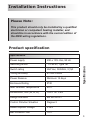
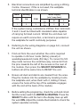
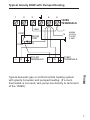
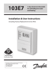
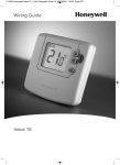
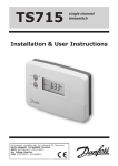
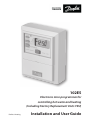
102E5 Electronic mini-programmer for controlling hot water and heating (Including Factory Replacement Units FRU) Danfoss Heating Installation and User Guide Index Installation Product specification 3 Installation 4-6 Wiring 6-9 Replacement 10-11 INDEX User Your programmer 12 Setting the clock 13 Factory preset programmes 14 Setting the programme - 24 hour 15 Setting the programme - 5/2 day 16 Running the programme 17 Temporary user overrides 18 Battery backup 19 Contact details 20 For a large print version of these instructions please call Marketing on 01234 364 621. ® Certification Mark 2 Danfoss can accept no responsibility for possible errors in catalogues, brochures, and other printed material. All trademarks in this material are property of the respective companies. Danfoss and the Danfoss logotype are trademarks of Danfoss A/S. All rights reserved. Installation Instructions Please Note: This product should only be installed by a qualified electrician or competent heating installer, and should be in accordance with the current edition of the IEEE wiring regulations. Product specification Power supply 230 ± 15% Vac, 50 Hz Switching action 1 x SPST, Type 1B Switch rating 264 Vac, 50/60Hz, 3(1)A Timing Accuracy ±1 min./month Power Reserve Minimum 14 days Enclosure Rating IP30 Max. Ambient Temperature 45°C Dimensions, mm (W, H, D) 103 x 137 x 48 Design standard EN 60730-2-7 Control Pollution Situation Degree 2 Rated Impulse Voltage 2.5kV Ball Pressure Test 75°C Specification Specification 3 Installation NB. For FRU units - go straight to point 6 below. 1. Loosen the fixing screw in the base of the unit to release the Wiring Cover. 2. Holding the unit face downwards, press firmly in the centre of the wallplate and slide it apart and lift it from the module. 3. Fix the wallplate and terminal block to the wall, or plaster box, as required. Ensure that the screw heads do not protrude beyond the vertical centre rib of the wallplate, or this will prevent the module correctly locating onto the wallplate. Vertical centre rib Installation Screw fixing holes (screwheads MUST NOT protrude above centre rib) Wallplate & Terminals 4. Surface cables can only enter from below the unit. Cut an appropriate cable aperture in the wiring cover. If the wallplate is mounted on a plaster box, cables can enter from the rear below the terminal block. 4 5. Electrical connections are simplified by using a Wiring Centre. However, if this is not used, the wallplate terminal identification is as shown. Water Heating Mains Supply (via 3 amp fuse) ON ON COM 1 2 3 N L 5 6 If the system being controlled is 230Vac then terminals 3 and L must be linked with insulated cable capable of carrying full load current. Whilst the unit does not require an earth connection, a terminal is provided on the wallplate for earth continuity purposes. 7. Find out from the user whether the unit is required to operate in 24-hour mode (factory preset) or weekday/weekend mode (5/2 day). To convert to 5/2 day mode remove the small two-way connector from the pins towards the left of the recess on the rear of the module, then press the SELECT/ADVANCE/+/buttons all at the same time to RESET the unit. 8. Ensure all dust and debris are cleared from the area. Plug the module into the wallplate by locating it onto the wallplate and, when flush with it, sliding it down, ensure the hook at the top of the wallplate engages with the slot at the back of the module. 9. Before setting the programme, check the unit and circuit. Set the rocker switch to WATER & HEATING. Press the SELECT button until the bar in the display lines up with the word ON. Adjust the remote thermostats to check the system operates correctly. Installation 6. Referring to the wiring diagrams on page 6-9, connect the unit as shown. 5 10. Then press the SELECT button until the bar lines up with the word OFF and check the system does not operate. 11. Set the rocker switch to WATER ONLY. Press the SELECT button until the bar in the display lines up with the word ON and check that the water circuit only operates. 12. When the circuit check has been completed, replace the wiring cover and tighten the fixing screw. Cut any cable aperture in the wiring cover which may be necessary to accommodate surface mounted cables. 13. Finally set time of day and programmes required, noting that the unit is supplied with a pre-set programme, as stated on Page 14. 02, 102E5, 102E7 Wiring Wiring 6 Typical Gravity DHW with Pumped Heating 2 1 5 3 6 102E5 TERMINALS LINK L COM N ROOM 'STAT L N N BOILER TERMINALS L N PUMP TERMINALS Typical domestic gas or oil-fired central heating system with gravity hot water and pumped heating. (If a room thermostat is not used, wire pump live directly to terminal 2 of the 102E5). Wiring CALL MAINS SUPPLY FUSED 3 AMP 7 Typical Heating and Hot Water control system using 3-port mid-position valve 2 1 5 3 6 102E5 TERMINALS LINK L ROOM 'STAT COM CALL N WHITE BLUE OR BROWN N CYL. 'STAT COM SAT CALL GREY RED OR ORANGE Wiring MID-POSITION VALVE 8 L N MAINS SUPPLY FUSED 3 AMP BOILER & PUMP TERMINALS The above control system is available as the Danfoss Randall 102E5 HEATSHARE pack, which also includes the TW room thermostat, AT cylinder thermostat, HS3 midposition valve and a WB12 wiring box. Typical Heating and Hot Water control system using 2-port zone valves 2 1 5 3 6 102E5 TERMINALS LINK COM L COM ROOM 'STAT SAT CALL CYL. 'STAT N N MAINS SUPPLY FUSED 3 AMP CALL HEATING VALVE N N L N BOILER & PUMP TERMINALS The above control system is available as the Danfoss Randall 102E5 HEATPLAN pack, which also includes the TW room thermostat, AT cylinder thermostat, two 22mm HPP zone valves and a WB12 wiring box. Wiring D.H.W VALVE 9 10 2 2 2 1,3 HORSTMANN DIAMOND 424 POTTERTON 423 SANGAMO S409 F1 & F4 SANGAMO (Early model) S410 Form 4 Boiler (8) HORSTMANN CORAL 423 & 424 2 4 RANDALL MKII R6 HORSTMANN DIAMOND 423 4 RANDALL 3020P, 3060 4 5 4 4 4 Air ‘Stat (8) 5 2 2 2 1 1 Heating ON Water ON RANDALL 102, 102E, 102E7 DANFOSS RANDALL 102E5 - - - - - - - - 3 3 COM Replacement N,2 N,1,3 N N N 2,3 3 1,7 5 5 (N) L L L,1,3 L,1,3 L,1,3 1 1,2 6 6 6 (L) MAINS SUPPLY (via 3 amp fuse) 4,6 5 5 5 4,7 6 3 A 6 6 5 7 5 B 6 6 C An additional terminal block is required where these disconnected leads (or pairs of leads) should be terminated 11 3 5 3 5 3 3 V 2 2 SMITHS IND. CENTROLLER 100 SMITHS IND. CENTROLLER 60 SMITHS IND. CENTROLLER 10 SMITHS IND. CENTROLLER 70 SWITCHMASTER 320, 350 SWITCHMASTER 600 VENNER VENOTROL VENNER VENOTROL 80 (Air ‘Stat) VENNER VENOTROL 80 (Air ‘Stat Linked) - - - - - - - - - Replacement 5 A/S S,F 1 1 4 2 4 2 N,1,3 N,1,3 N,A,M N N 1 N 1 N L L L,L1 L 4,L 2 L 2 L A/S,5 T,P 2 2 3 1,4 3 1 0 4 6 4 User Instructions Your programmer Your 102E5 mini-programmer allows you to switch your heating and hot water on and off at times that suit you. Overview The 102E5 can provide 3 ON periods and 3 OFF periods each day and can offer either 24 hour control (same programme for each day of the week) or 5/2 day control (one set of programmes for weekdays and a different set for weekends). 12 + - PROGRAMME Before you start Open the flap on the front of the unit. Press all four buttons (SELECT / ADVANCE / + / -) at the same time - + PROGRAMME Setting the clock Press PROGRAMME once + - PROGRAMME + - PROGRAMME Use + and – buttons to set the correct time (press and hold to change in 10 min increments). When time is correct press PROGRAMME again. In 24 hour mode this will take you straight to programming mode, where you can select your own ON and OFF times. Setting the time & the programme This will reset the unit, reinstate the preset programmes and set the time to 12:00pm on Monday. In 5/2 day mode this first will allow you to programme the correct DAY. To do this: use the + or – buttons to select the correct day press PROGRAMME again to enter programming mode 13 Factory Presets Factory preset programmes The unit is supplied with the following preset programme which will be active after the unit has been reset. Mon-Fri or All days in 24hr mode Sat-Sun* (5/2day mode only*) 1st ON 6.30am 7.30am 1st OFF 8.30am 10.00am 2nd ON 12.00pm 12.00pm 2nd OFF 12.00pm 12.00pm 3rd ON 5.00pm 5.00pm 3rd OFF 10.30pm 10.30pm NB. 2nd ON and 2nd OFF are set to the same time. These 2 times are ignored by the programme therefore the heating will just come on once in the morning and once in the evening. If you want the heating to come on in the middle of the day set the 2nd ON and 2nd OFF to the times you require. Accepting the preset times If you are happy to use the settings above, you don’t need to do anything else. To accept the presets press the PROGRAMME button until the colon in the display begins to flash. Your unit is now in RUN mode. 14 Programming event times in 24 hour mode You can programme your heating and hot water to come on and go off up to 3 times each day, to suit your requirements. 1 Use the + and - buttons to set the time you want your system to first come on in the morning Press PROGRAMME again to move to the next step (Event 2) Use the + and - buttons to set the time you want your system to first go off. Continue using the PROGRAMME and +/- buttons in this way to set the ON/OFF times for events 3-6 (2nd ON/OFF & 3rd ON/OFF). NB. It is not possible to programme times out of sequence. Programming the unit - 24 hour mode Press PROGRAMME until 1 (Event 1) shows along the top of the display. If you do not press a button at all for 3 or 4 minutes the unit will automatically return to RUN mode. 15 Programming event times in 5/2 day mode You can programme your heating and hot water to come on and go of up to 3 times each day, to suit your requirements, with one set of programmes for weekdays and a different set of programmes for the weekend. Programming the unit - 5/2 day mode Weekdays (MOTUWETHFR) Press PROGRAMME until 1 (Event 1) shows along the top of the display and MOTUWETHFR shows along the bottom. 1 Use the + and - buttons to set the time you want your system to first come on in the morning Press PROGRAMME again to move to Event 2 Use the + and - buttons to set the time you want your system to first go off. Continue using the PROGRAMME and +/- buttons in this way to set the ON/OFF times for events 3-6 for weekdays. Weekend (SASU) Press PROGRAMME again until 1 (Event 1) shows along the top of the display and SASU shows along the bottom of the display. Use the PROGRAMME and +/- buttons to set the ON/OFF times for the weekend. If at any time you wish to return to the factory preset programme, press SELECT / ADVANCE / + / - buttons together at the same time to reset the unit. 16 NB. It is not possible to programme times out of sequence. Running your programme The 102E5 will either control your hot water and heating together, or just your hot water (i.e. during the summer, when heating is no longer required). To make your selection use the rocker switch under the LCD display to select either WATER/HEATING or WATER ONLY As you press SELECT a bar on the display will move between ON, OFF, ALLDAY and AUTO ON = the hot water/heating will remain on constantly OFF = the hot water/heating will not come on AUTO = the hot water/heating will come on and go off according to the programmed times ALLDAY Y = the unit will come on at the first programmed ON and will remain on until the last programmed OFF Select the option you require, depending on your circumstances, time of year, etc. RUN mode To run the central heating and/or hot water programme press the SELECT button. 17 Temporary User Overrides Sometimes you may need to change the way you use your heating temporarily, i.e due to unusually cold weather. The 102E5 has two convenient overrides which can be selected without affecting the set programme. Override buttons Override buttons +1HOUR Press +1HOUR once if you need an extra hour of operation (a red light will come on). If the system is off it will come on for an hour. If it is already on it will add an extra hour so the system stays on for an extra hour. To cancel the override press +1HOUR again (red light will go off). ADVANCE (does not work when unit set to OFF) Press the ADVANCE button once to advance to the next programmed event (a red light will come on). If the system is on it will go off. If it is off it will come on. The set programme will resume at the next programmed ON/OFF time To cancel the override press ADVANCE again (red light will go off). 18 Battery backup In the event of a power cut, the built-in lithium battery will keep your time and programme settings for up to 15 days. After 15 days without mains power the unit will switch off and two dots will show in the display. However all your programmed on/off times will be remembered. Battery backup When the mains power is restored, the unit will need to be reactivated by pressing the PROGRAMME button, and the time and day will need to be set (see page 13). 19 Still having problems? Call your local heating engineer: Name: Tel: Visit our website: www.heating.danfoss.co.uk Email our technical department: [email protected] Call our technical department 01234 364 621 (9.00-5.00 Mon-Thurs, 9.00-4.30 Fri) Danfoss Ltd Ampthill Road Bedford MK42 9ER Tel: 01234 364621 Fax: 01234 219705 Part No 2467v04 Issue 4 01/15