1
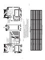
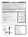
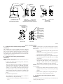
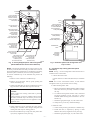
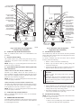
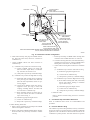
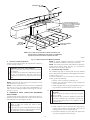
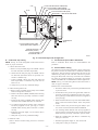
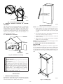
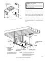
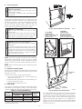
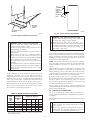
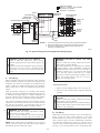
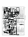
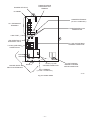
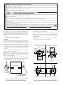
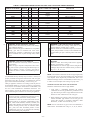
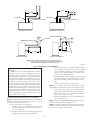
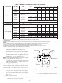
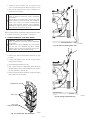
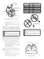
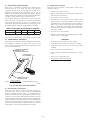
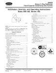
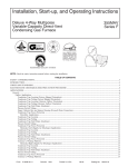
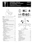
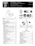
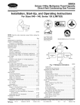
PLUG
CAP
COLLECTOR BOX
DRAIN TUBE (BLUE
& WHITE STRIPED)
COLLECTOR BOX
TUBE (PINK)
PLUG
CAP
COLLECTOR BOX
DRAIN TUBE (BLUE
& WHITE STRIPED)
COLLECTOR BOX
TUBE (GREEN)
COLLECTOR BOX
TUBE (PINK)
INDUCER HOUSING
(MOLDED) DRAIN
TUBE (BEHIND
COLLECTOR BOX
DRAIN TUBE)
COLLECTOR BOX
DRAIN TUBE (BLUE)
COLLECTOR BOX
TUBE (GREEN)
CONDENSATE
TRAP
COLLECTOR BOX
DRAIN TUBE (BLUE)
FIELD-INSTALLED
FACTORY-SUPPLIED
DRAIN TUBE
COUPLING (LEFT
DRAIN OPTION)
CONDENSATE
TRAP
FIELD-INSTALLED
FACTORY-SUPPLIED
DRAIN TUBE
FIELD-INSTALLED
FACTORY-SUPPLIED
CPVC STREET
ELBOWS (2) FOR
LEFT DRAIN OPTION
1⁄2-IN.
INDUCER
HOUSING
DRAIN TUBE
(VIOLET)
FIELD-INSTALLED
FACTORY-SUPPLIED
DRAIN TUBE
COUPLING (RIGHT
DRAIN OPTION)
A00288
D. Condensate Trap Tubing (Alternate Upflow
Orientation)
NOTE: See Fig. 7 or tube routing label on main furnace door to
confirm location of these tubes.
NOTE: If the alternate left-hand side of casing location is used,
the factory-connected drain and relief port tubes must be disconnected and modified for attachment. See Condensate Trap Tubing
(Alternate Upflow Orientation) section for tubing attachment.
To relocate condensate trap to the left-hand side, perform the
following:
1. Collector Box Drain Tube
Connect collector box drain tube (blue label) to condensate
trap.
1. Remove 3 tubes connected to condensate trap.
2. Remove trap from blower shelf by gently pushing tabs
inward and rotating trap.
NOTE: On 17-1/2-in. wide furnaces ONLY, cut tube between
corrugated sections to prevent kinks from occurring.
3. Install casing hole filler cap (factory-supplied in loose parts
bag) into blower shelf hole where trap was removed.
→
A00289
Fig. 7—Alternate Upflow Tube Configuration and
Trap Location
Fig. 6—Factory-Shipped Upflow Tube Configuration
(Shown With Blower Access Panel Removed)
2. Inducer Housing Drain Tube
a. Remove and discard LOWER (molded) inducer housing
drain tube which was previously connected to condensate trap.
WARNING: CARBON MONOXIDE POISONING
HAZARD
Failure to follow this warning could result in personal
injury or death.
Casing hole filler cap must be installed in blower shelf
hole when condensate trap is relocated to prevent combustion products being drawn in from appliances in the
equipment room.
b. Use inducer housing drain extension tube (violet label
and factory-supplied in loose parts bag) to connect
LOWER inducer housing drain connection to the condensate trap.
c. Determine appropriate length, cut, and connect tube.
d. Clamp tube to prevent any condensate leakage.
3. Relief Port Tube
4. Install condensate trap into left-hand side casing hole by
inserting tube connection stubs through casing hole and
rotating until tabs snap into locking position.
a. Connect relief port tube (green label) to condensate trap.
b. Extend this tube (if required) by splicing to small
diameter tube (factory-supplied in loose parts bag).
5. Fill unused condensate trap casing holes with plastic filler
caps (factory-supplied in loose parts bag).
c. Determine appropriate length, cut, and connect tube.
—7—