1
Pico™ Controller
Bulletin 1760
Getting Results
Important User Information
Solid state equipment has operational characteristics differing from those of
electromechanical equipment. Safety Guidelines for the Application,
Installation and Maintenance of Solid State Controls (Publication SGI-1.1
available from your local Rockwell Automation sales office or online at
http://www.ab.com/manuals/gi) describes some important differences
between solid state equipment and hard-wired electromechanical devices.
Because of this difference, and also because of the wide variety of uses for
solid state equipment, all persons responsible for applying this equipment
must satisfy themselves that each intended application of this equipment is
acceptable.
In no event will Rockwell Automation, Inc. be responsible or liable for
indirect or consequential damages resulting from the use or application of
this equipment.
The examples and diagrams in this manual are included solely for illustrative
purposes. Because of the many variables and requirements associated with
any particular installation, Rockwell Automation, Inc. cannot assume
responsibility or liability for actual use based on the examples and diagrams.
No patent liability is assumed by Rockwell Automation, Inc. with respect to
use of information, circuits, equipment, or software described in this manual.
Reproduction of the contents of this manual, in whole or in part, without
written permission of Rockwell Automation, Inc. is prohibited.
Throughout this manual, when necessary we use notes to make you aware of
safety considerations.
WARNING
IMPORTANT
ATTENTION
Identifies information about practices or circumstances
that can cause an explosion in a hazardous environment,
which may lead to personal injury or death, property
damage, or economic loss.
Identifies information that is critical for successful
application and understanding of the product.
Identifies information about practices or circumstances
that can lead to personal injury or death, property
damage, or economic loss. Attentions help you:
• identify a hazard
• avoid a hazard
• recognize the consequence
SHOCK HAZARD
Labels may be located on or inside the equipment (e.g.,
drive or motor) to alert people that dangerous voltage may
be present.
BURN HAZARD
Labels may be located on or inside the equipment (e.g.,
drive or motor) to alert people that surfaces may be
dangerous temperatures.
Table of Contents
Preface
Who Should Use this Manual. . . . . . . . . . .
Purpose of This Manual. . . . . . . . . . . . . . .
Common Techniques Used in this Manual .
Rockwell Automation Support . . . . . . . . . .
.
.
.
.
.
.
.
.
.
.
.
.
.
.
.
.
.
.
.
.
.
.
.
.
.
.
.
.
. Preface-i
. Preface-ii
. Preface-ii
Preface-iii
Chapter 1
Pico Controller
Safety Information. . . . . .
Simply Pico. . . . . . . . . . .
Mount Pico . . . . . . . . . . .
Connect Pico . . . . . . . . .
Pico Operating Principle .
Menu Structure . . . . . . . .
.
.
.
.
.
.
.
.
.
.
.
.
.
.
.
.
.
.
.
.
.
.
.
.
.
.
.
.
.
.
.
.
.
.
.
.
.
.
.
.
.
.
.
.
.
.
.
.
.
.
.
.
.
.
.
.
.
.
.
.
.
.
.
.
.
.
.
.
.
.
.
.
.
.
.
.
.
.
.
.
.
.
.
.
.
.
.
.
.
.
.
.
.
.
.
.
.
.
.
.
.
.
.
.
.
.
.
.
.
.
.
.
.
.
.
.
.
.
.
.
.
.
.
.
.
.
.
.
.
.
.
.
.
.
.
.
.
.
.
.
.
.
.
.
.
.
.
.
.
.
1-1
1-1
1-3
1-4
1-10
1-15
Operation of Pico . . . . . . . . . . . . . .
Set the Menu Language . . . . . . . . . .
Set the Time . . . . . . . . . . . . . . . . . .
Choose Pico Operating Mode . . . . .
Pico Circuit Diagram Elements. . . . .
Example: Creating a Circuit Diagram
Function Relay Types . . . . . . . . . . .
Example: Use a Function Relay . . . .
Basic Circuits . . . . . . . . . . . . . . . . .
.
.
.
.
.
.
.
.
.
.
.
.
.
.
.
.
.
.
.
.
.
.
.
.
.
.
.
.
.
.
.
.
.
.
.
.
.
.
.
.
.
.
.
.
.
.
.
.
.
.
.
.
.
.
.
.
.
.
.
.
.
.
.
.
.
.
.
.
.
.
.
.
.
.
.
.
.
.
.
.
.
.
.
.
.
.
.
.
.
.
.
.
.
.
.
.
.
.
.
.
.
.
.
.
.
.
.
.
.
.
.
.
.
.
.
.
.
.
.
.
.
.
.
.
.
.
.
.
.
.
.
.
.
.
.
.
.
.
.
.
.
.
.
.
.
.
.
.
.
.
.
.
.
2-1
2-2
2-3
2-4
2-5
2-9
2-13
2-20
2-23
.
.
.
.
.
.
.
.
.
.
.
.
.
.
.
.
.
.
.
.
.
.
.
.
.
.
.
.
.
.
.
.
.
.
.
.
.
.
.
.
.
.
.
.
.
.
.
.
.
.
.
.
.
.
.
.
.
.
.
.
.
.
.
.
.
.
.
.
A-1
A-1
A-3
A-4
Chapter 2
Drawing a Circuit with Pico
Chapter 3
Pico Interface Socket
Appendix A
Specifications
Physical Specifications. .
Product Selection Table.
Accessories . . . . . . . . . .
Dimensions. . . . . . . . . .
.
.
.
.
.
.
.
.
.
.
.
.
.
.
.
.
.
.
.
.
.
.
.
.
.
.
.
.
.
.
.
.
.
.
.
.
Index
i
Publication 1760-GR001C-EN-P - April 2005
Table of Contents
ii
Publication 1760-GR001C-EN-P - April 2005
Preface
Read this preface to familiarize yourself with the rest of the manual. It
provides information concerning:
•
•
•
•
•
Who Should Use this
Manual
who should use this manual
the purpose of this manual
related documentation
conventions used in this manual
Rockwell Automation support
Use this manual if you are responsible for designing, installing,
programming, or troubleshooting control systems that use Pico
controllers.
You should have a basic understanding of electrical circuitry and
familiarity with relay logic. If you do not, obtain the proper training
before using this product.
i
Publication 1760-GR001C-EN-P - April 2005
Preface
ii
Purpose of This Manual
This manual provides a basic overview of Pico and an introduction to
Pico programming. For a more detailed description of how to install
and use your Pico Controller, refer to publication 1760-UM001, Pico
Controller User Manual.
Related Documentation
The following documents contain additional information concerning
Rockwell Automation products. To obtain a copy, contact your local
Rockwell Automation office or distributor.
For
Read this Document
Document Number
A more detailed description of how to install and use your Pico
controller.
Pico Controller User Manual
1760-UM001
In-depth information on grounding and wiring Allen-Bradley
programmable controllers
Allen-Bradley Programmable
Controller Grounding and Wiring
Guidelines
1770-4.1
A description of important differences between solid-state
programmable controller products and hard-wired electromechanical
devices
Application Considerations for
Solid-State Controls
SGI-1.1
An article on wire sizes and types for grounding electrical equipment
National Electrical Code - Published by the National Fire
Protection Association of Boston, MA.
A complete listing of current documentation, including ordering
instructions. Also indicates whether the documents are available on
CD-ROM or in multi-languages.
Allen-Bradley Publication Index
SD499
A glossary of industrial automation terms and abbreviations
Allen-Bradley Industrial Automation
Glossary
AG-7.1
Common Techniques Used
in this Manual
Publication 1760-GR001C-EN-P - April 2005
The following conventions are used throughout this manual:
• Bulleted lists such as this one provide information, not
procedural steps.
• Numbered lists provide sequential steps or hierarchical
information.
• Italic type is used for emphasis.
Preface
Rockwell Automation
Support
iii
Rockwell Automation offers support services worldwide, with over 75
Sales/Support Offices, 512 authorized Distributors and 260 authorized
Systems Integrators located throughout the United States alone, plus
Rockwell Automation representatives in every major country in the
world.
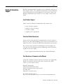
Local Product Support
Contact your local Rockwell Automation representative for:
•
•
•
•
sales and order support
product technical training
warranty support
support service agreements
Technical Product Assistance
If you need to contact Rockwell Automation for technical assistance,
please review the Troubleshooting chapter in the Pico Controller User
Manual first. Then call your local Rockwell Automation representative.
You can also contact Rockwell Automation Technical Support. To
reach our Technical Support, go to the following website to find the
support site for your region.
• http://support.automation.rockwell.com/contactinformation/
Your Questions or Comments on this Manual
If you find a problem with this manual, or you have any suggestions
for how this manual could be made more useful to you, please
contact us at the address below:
Rockwell Automation
Control and Information Group
Technical Communication, Dept. A602V
P.O. Box 2086
Milwaukee, WI 53201-2086
or visit our internet page at:
http://www.ab.com/pico or http://www.rockwellautomation.com
Publication 1760-GR001C-EN-P - April 2005
Preface
iv
Publication 1760-GR001C-EN-P - April 2005
Chapter
1
Pico Controller
Safety Information
ATTENTION
Electrical Shock Hazard
The electrical installation and commissioning work
must only be carried out by suitably qualified
personnel.
Do not work on the device when the power is turned
on.
Observe the relevant safety regulations:
• Turn off the power
• Make sure that the device cannot be powered on
again inadvertently
• Check to make sure that no dangerous voltages
are present before working on the device
Simply Pico
Clever Switching and Controlling
Pico is a compact, user-friendly and low-cost controller for simple
control applications. Applications range from building and domestic
automation to machine and plant control. Pico has built-in
user-friendly operating elements and an LCD display.
Connect Pico and draw a circuit diagram on the display by pressing
the buttons on the device. Pico works with make contacts, break
contacts, and relays.
Enter a circuit diagram in Pico just like it is sketched on paper. Pico
has basic and advanced functions for relays, time switches and
contactors, among other functions. Make changes to the circuit by
pressing the buttons on the device. Time consuming rewiring is not
necessary.
1
Publication 1760-GR001C-EN-P - April 2005
1-2
Pico Controller
Applications Everywhere
• Building and domestic automation, controllers for lighting,
doors, window shutters
• Control ventilators, rotating doors, greenhouses, exterior
lighting, window controllers, shop display lighting
• Create controllers for temperature, ventilation and brightness
levels
• Control machines and plant, presses, conveyor belts, oscillating
conveyors, sorters, pumps
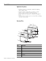
Overview of Pico
1
7
2
Del
Alt
3
4
8
Esc
7
Del
Ok
5
Alt
8
Esc
6
Ok
5
8
3
5
Publication 1760-GR001C-EN-P - April 2005
Item
Description
1
Incoming Power
2
Inputs
3
Power/Run LED
4
Keypad
5
Socket for memory module or PC interface cable
6
Outputs
7
LCD display
8
Write-On Surface
Pico Controller
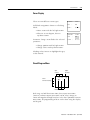
Mount Pico
Mount on DIN Rail
1-3
1
1. Hook Pico to the top edge of the DIN rail
and rotate into place while pressing down
slightly as shown by the arrow.
2. Pico will clip into place and is secured by
the built-in spring mechanism.
Mount on a Mounting Plate
2
Pico can be screwed to a mounting plate with the three or four feet
which are included.
Click
Publication 1760-GR001C-EN-P - April 2005
1-4
Pico Controller
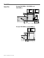
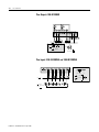
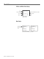
Connect Pico
Pico Inputs1760-L12BBB-xx, 1760-L12BWB-xx and
1760-L12DWD-xx
28.8 V
1 ≥ 15 V
15.6 V
l = 3.3 mA/24 V
I7, I8 = 2.2 mA/24 V 1 ≥ 8 V
l = 3.3 mA/12 V
I7, I8 = 1.1 mA/12 V
BWB 0 ≤ 4 V
DWD
0≤ 5V
BWB: +24 V
DWD: +12 V
l7, l8
0V
~
>1 A
BWB:
U e = 24 V
(20.4 - 28.8 V)
Ie = 80 mA
0V
+10 V
5 - 7 lb-in
3.5 mm
10 V
DWD:
U e = 12 V
(10.2 - 15.6 V)
Ie = 140 mA
5V
+.. V
BWB: +24 V
DWD: +12 V
l1
COM
I3
I2
I4
I5
I6
I7
0V
0
I8
Pico Inputs 1760-L12AWA-xx and 1760-L12NWA-xx
264V
l1–I6 = 0.5 mA 240 V
l1–I6 = 0.25 mA 120 V
I7, I8
l = 6 mA 240 V
l = 4 mA 120V
1 ≥ 79V
0 ≤ 40V
L1
L2
>1A
Ue = 120/240 V
50/60 Hz
(90 to 264V)
le = 40 mA 120V
20 mA 240V
5-7 lb-in.
3.5 mm
L1
Publication 1760-GR001C-EN-P - April 2005
L2
l1
I2
I3
I4
I5
I6
I7
I8
5
10
Pico Controller
1-5
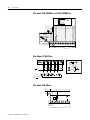
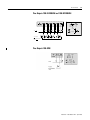
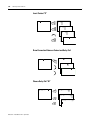
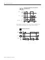
Pico Outputs 1760-L12AWA-xx, 1760-L12BWB-xx,
1760-L12DWD-xx, 1760-L12BBB-xx and 1760-L12NWA-xx
1
Q1
2
2
1
1
2
Q3
Q2
2
1
L
R
Q4
24 V
120 V
240 V
10 000 000
8A
8A
8A
2A
2A
2A
1000 W
0V
,N
10 x 58 W
25.000
8 A / B 16
L1, L2, L3 (120/240 V )
+ 24 V
Pico Inputs 1760-L18BWB-EX and 1760-L18BWB-EXND
I1–I6, I9–I12 = 3.3 mA
24 V
I7, I8 = 2.2 mA
24 V
28.8 V
1 ≥ 15 V
0 ≤ 5V
+24 V
0V
l7, I8
z
>1 A
0V
+10 V
5
10
U e = 24 V
(20.4–28.8 V )
Ie = 140 mA
10 V
5V
5–7 lb-in
3.5 mm
0V
+24 V
24 V
COM
l1
I2
I3
I4
I5
I6
I7
I8
0
I9
I10 I11 I12
Input 24 V
-
G '1D %
B
Publication 1760-GR001C-EN-P - April 2005
1-6
Pico Controller
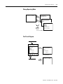
Pico Inputs 1760-L18AWA-xx and 1760-L18NWA-xx
264 V
l1–I6, I9 –I12 = 0.5 mA 240 V
l1–I6, I9 –I12 = 0.25 mA 120 V
I7, I8
l = 6 mA 240 V
l = 4 mA 120 V
1 > 79 V
0 < 40 V
L1
L2
>1A
Ue = 120/240 V
50/60 Hz
(85–264 V)
le = 70 mA 120 V
35 mA 240 V
5-7 lb-in.
3.5 mm
L1
l1
L2
I3
I2
100/240 V
I4
I5
I6
I7
I8
I9
I10 I11 I12
Input 100/240 V
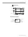
Pico Outputs 1760-L18xxx
1 2
Q1
< 10 000 000
1 2
Q2
1 2
Q3
1
1 2
Q4
2
Q5
1 2
R
Q6
24 V
120 V
240 V
8A
8A
8A
2A
2A
2A
1000 W
0V
,N
10 x 58 W
8 A / B 16
L1, L2, L3 (120/240 V
+ 24 V
)
Pico Inputs 1760-L20xxx
L011
L012
F1
+...V
0V
DC : +24 V
DA : +12 V
Publication 1760-GR001C-EN-P - April 2005
l1
I2
I7
< 25.000
Pico Controller
1-7
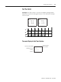
Pico Outputs 1760-L20xxx
+24 VQ
0 VQ
Q1 Q2
Q3 Q4
Q5 Q6
Q7 Q8
F 10 A
0VH
R
f 2.5 A
+ 24 V H
(20.4 – 28.8 V H)
24 V H
0.5 A
0.5 A
5 W/24 V
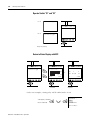
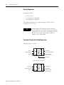
Pico Inputs 1760-IB12XOB8
28.8 V
1 ≥ 15 V
R1–R12 = 3.3 mA; 24 V
0≤ 5V
+24 V
0V
>1 A
5–7 lb-in
U e = 24 V
(20.4 –28.8 V )
Ie = 140 mA
3.5 mm
NC NC
R1 R2 R3 R4
R5
R6
Input 24 V
R7
R8 R9
R10 R11 R12 +24V
COM
24 V
Publication 1760-GR001C-EN-P - April 2005
1-8
Pico Controller
Pico Outputs 1760-IB12XOB8
S1 S2
S3 S4
S5 S6
S7
S8
+24V dc COM
10A
0V
R
24V
0.5A
≤ 2.5A
0.5A
5W/24V
+ 24V dc
(20.4-28.8V dc
)
Pico Inputs 1760-IA12XOW6I and 1760-IB12XOW6I
1 2
S1
10 000 000
1 2
S2
1 2
S3
1
1 2
S4
S5
2
1 2
S6
R
24 V
120 V
240 V
8A
8A
8 A
2A
2A
2A
1000 W
0V
,N
< 8 A / B 16
L1, L2, L3 (120/240 V)
+ 24 V
Publication 1760-GR001C-EN-P - April 2005
10 x 58 W
25.000
Pico Controller
1-9
Pico Outputs 1760-IA12XOW6I and 1760-IB12XOW6I
1 2
S1
10 000 000
1 2
S2
1 2
S3
1
1 2
S4
S5
2
1 2
S6
R
24 V
120 V
240 V
8A
8A
8 A
2A
2A
2A
1000 W
0V
,N
10 x 58 W
25.000
< 8 A / B 16
L1, L2, L3 (120/240 V)
+ 24 V
Pico Outputs 1760-OW8
Publication 1760-GR001C-EN-P - April 2005
1-10
Pico Controller
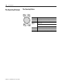
Pico Operating Principle
Pico Operating Buttons
Del
Esc
Alt
Ok
Button
Function
Del
Delete object in the circuit diagram
Alt
Special functions in the circuit diagram
Cursor
Buttons
Move cursor
Select menu item
Choose contact numbers, values, times, etc.
Publication 1760-GR001C-EN-P - April 2005
Ok
Next menu level, store your entry
Esc
Previous menu level, cancel your entry
Pico Controller
1-11
Move Through Menus to Choose Values
Press
To
Show system menu (press both keys at the same time).
Del
and
Alt
• Go to next menu level.
• Select menu item.
Ok
• Store your entry.
Cancel your entry since the last Ok.
Esc
• Change menu item.
• Change value.
• Change position.
12-Point Status Display
Inputs
I12345678
MO
12:50
Outputs
Q1234
On/
RUN
Weekday
Time
RUN/STOP mode
Off
Publication 1760-GR001C-EN-P - April 2005
1-12
Pico Controller
18-Point and 20-Point Status Display
Inputs
Retention Enabled
1...5..8....
RE
I
P
Debounce Enabled/P-Buttons Enabled
Day, Time
MO 02:00 ST
Start-up Mode
Outputs
.2..5..8
Mode
RUN
Inputs 1, 5, 8 ON
Outputs 2, 5, 8 ON
Menu Display
Current choice
blinks in the Pico
menu
PROGRAM...
PASSWORD..
RUN...
RUN...
PARAMETER
PARAMETER
SET CLOCK..
SET CLOCK..
Main menu with and without password enabled
Publication 1760-GR001C-EN-P - April 2005
Pico Controller
1-13
Cursor Display
There are two different cursor types:
WINTER
TIME
Full block navigation is shown as a flashing
block:
DAY
MO
:
TIME :
• Move cursor with the left/right arrows
• When in circuit diagram, also use
up/down arrows
Parameter change cursor flashes the selected
parameter:
01 25
WINTER
TIME
DAY
MO
:
TIME :
01:25
• Change position with left/right arrows
• Change values with up/down arrows
Flashing values/menus are highlighted in grey
in this manual.
Circuit Diagram Menu
Input
Contacts
Circuit
Connections/Rungs
Output
Coil Field
I1 -I2 -T1 -{Q1
I2 - 1
Branch Connections
Each rung can hold four instructions, three input instructions
(contacts) and one output instruction (coil or relay). Rungs are
connected together through branches at the three positions between
instructions. All programming of Pico can be done using the display
and keypad.
Publication 1760-GR001C-EN-P - April 2005
1-14
Pico Controller
Circuit Diagram Symbols
P
I
Q
M
T
C
Cursor button as input
Contact for input
Contact for output
Contact for internal marker bits
Contact for timer relay
Contact for counter relay
Contact for real time clock switch
A
D
Analog comparator contact
Contact for text display (1)
:
R
S
Contact for jump (1)
Expansion Inputs (1)
Contact for internal marker relay or
Expansion Output (1)
Coil Field
I1 -M2 -T1 -{Q1
I2 -Q1
I3-M2-T2----{Q2
1st circuit connection
2nd circuit connection
3rd circuit connection
…
41st circuit connection
…
Last circuit connection
(1) For 1760-L18xxx only
Publication 1760-GR001C-EN-P - April 2005
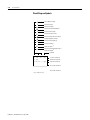
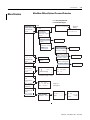
Pico Controller
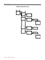
Menu Structure
1-15
Main Menu Without Optional Password Protection
STOP: Circuit diagram menu
RUN: Power flow display
PROGRAM...
STOP RUN å
PARAMETER
INFO...
SET CLOCK
RUN
Circuit Diagram
STOP
Parameters
PROGRAM
DELETE PROG
CARD ...
PROGRAM
DELETE PROG
CARD ...
DELETE ?
PROGRAM
DELETE PROG
CARD ...
PROGRAM...
STOP RUN
PARAMETER
INFO...
SET CLOCK
PROGRAM...
STOP RUN
PARAMETER
INFO...
SET CLOCK
DEVICE->CARD
CARD->DEVICE
DELETE CARD
REPLACE ?
DEVICE->CARD
CARD->DEVICE
DELETE CARD
RUN
DEVICE->CARD
CARD->DEVICE
DELETE CARD
STOP
T1 X
S
T2 Ü
M:S
C1
N
Parameter
Display
O1
Parameter
Display
T1 X
+
+
+
+
REPLACE ?
DELETE ?
S +
S1 10.000
S2 +0
T:
Information Display of Device
PROGRAM...
RUN
PARAMETER
INFO...
SET CLOCK
DC TC LCD
OS: 1.00.027
CRC: 02752
PROGRAM...
RUN
PARAMETER
INFO...
SET CLOCK
SET CLOCK
SUMMER TIME
Display for
Setting Clock
HH:MM --:--
HH:MM 14:23
DD.MM --.----YEAR
DD.MM 17.03
2004
YEAR
Publication 1760-GR001C-EN-P - April 2005
1-16
Pico Controller
Main Menu Setting Summer Time
PROGRAM...
RUN
PARAMETER
INFO...
SET CLOCK
SET CLOCK
SUMMER TIME
SET CLOCK
SUMMER TIME
SET CLOCK
SUMMER TIME
SET CLOCK
SUMMER TIME
NONE
RULE...
EU
GB
US
NONE
RULE...
EU
GB
US
å
SUMMER START
SUMMER END
AM
HH:MM
---DD.MM:00.00
HH.MM:00:00
DIFF: 0:00
NONE
RULE...
EU
GB
US
NONE
RULE...
EU
GB
US
SUMMER START
SUMMER END
SUMMER START
SUMMER END
AM
HH:MM
---DD.MM:00.00
HH.MM:00:00
DIFF: 0:00
Publication 1760-GR001C-EN-P - April 2005
Pico Controller
1-17
Main Menu with Password Protection
Password Entry
Main Menu
PASSWORD... Unlock
RUN
PARAMETER
INFO...
SET CLOCK
Password
Four Wrong
Entries
DELETE ALL
Correct Entry
Status Display
PASSWORD...
RUN
TIP
If you do not know the password, you can delete the
old password, but the circuit diagram and data will
also be deleted. To delete the password, press Ok to
DELETE ALL after entering four incorrect passwords.
(Pressing Esc retains the circuit diagram and data.
You can then make another four attempts to enter
the password.)
Publication 1760-GR001C-EN-P - April 2005
1-18
Pico Controller
System Menu
System
sECURITY...
SYSTEM...
LANGUAGE ...
CONFIGURATOR
Password Entry
Set Password
Password
RANGE...
DEBOUNCE OFF
P ON
STOP MODE
DEBOUNCE OFF
DEBOUNCE OFF
P ON
STOP MODE
DEBOUNCE OFF
P ON
STOP MODE
DEBOUNCE OFF
P ON
STOP MODE
(2)
RETENTION ON
SECURITY...
SYSTEM...
LANGUAGE...
CONFIGURATOR
Publication 1760-GR001C-EN-P - April 2005
ENTER PASSW:
XXXX
CHANGE PW
ACTIVATE PW
PROGRAM
å
PARAMETER
CLOCK
OPRTNG MODE
INTERFACE
DELETE FUNCT
Password
RANGE...
SECURITY...
SYSTEM...
LANGUAGE...
CONFIGURATOR
CHANGE PW
ACTIVATE PW
Change Password
ACTIVATE PW
CHANGE PW
SECURITY...
SYSTEM...
LANGUAGE...
CONFIGURATOR
ENTER PASSW:
XXXX
DEBOUNCE ON
P ON
P OFF
MODE: STOP
MODE: RUN
RETENTION ON (2)
RETENTION OFF (2)
ENGLISH
DEUTSCH
FRANCAIS
ESPANOL
ITALIANO
PORTUGUES
NEDERLANDS
SVENSKA
POLSKI
TURKCE
CESKY
MAGYAR
(1) Only for Pico 1760-L18xxx
(2) Only for Pico 1760-L12BWB-xx,
-L12DWD and -L18xxx.
PROGRAM
PARAMETER
CLOCK
OPRTNG MODE
INTERFACE
DELETE FUNCT
å
å
å
å
å
å
Chapter
2
Drawing a Circuit with Pico
Operation of Pico
Buttons for Drawing Circuit Diagrams
Button
Function
Delete branch, contact, relay, or empty rung in the
circuit diagram
Del
Alt
• Toggle between break and make contact
• Connect contacts and relays
• Add circuit connections
Up/down arrows:
• Change value
• Move cursor up and down
Left/right arrows:
• Move cursor to left and right
• Change between parameters
• Go to previous menu level
• Undo settings from previous Ok
Esc
• Exit current display
• Go to next menu level
Ok
• Change, add contact/relay
• Save setting
1
Publication 1760-GR001C-EN-P - April 2005
2-2
Drawing a Circuit with Pico
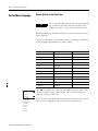
Set the Menu Language
Power Up Pico for the First Time
TIP
A brief current surge is produced when powering on
the unit for the first time. Do not switch the unit
using reed contacts, since these may burn or melt.
When you power-up Pico for the first time, you are asked to select the
menu language.
Use the up and down cursor buttons to select a language. Definitions
of the language abbreviations are shown below.
ENGLISH
DEUTSCH
FRANCAIS
ESPANOL
ITALIANO
PORTUGUES
NEDERLANDS
SVENSKA
POLSKI
TURKCE
CESKY
MAGYAR
Publication 1760-GR001C-EN-P - April 2005
Language
LCD display
Abbreviaton
English
ENGLISH
GB
German
DEUTSCH
D
French
FRANCAIS
F
Spanish
ESPANOL
E
Italian
ITALIANO
I
Portuguese
PORTUGUES
–
Dutch
NEDERLANDS
–
Swedish
SVENSKA
–
Polish
POLSKI
–
Turkish
TURKCE
–
Czexh
CESKY
–
Hungarian
MAGYAR
–
Press Ok to confirm your choice or press Esc to exit the menu. The
unit then switches to the status display. You can also change the
language setting at a later date.
If you do not set the language, Pico displays this menu and waits for
you to select a language every time the unit is powered up.
Drawing a Circuit with Pico
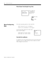
Set the Time
2-3
Controllers with the “-NC” designation do not have real time clocks.
Set the Real Time Clock
PROGRAM ...
1 ...5 ..8 ....
I 12 3 4 5 6 7 8
MO
14:15
Q1234
12-I/O Pico
STOP
RE
I
or
MO
P
RUN
Ok
PARAMETER
ST
02:00
PROGRAM ...
.2 ..5 ..8
RUN
RUN
PARAMETER
18-I/O Pico
SET CLOCK
SET CLOCK
Ok
SUMMER TIME
Set Week Day and Time
SET CLOCK
WINTER TIME
Ok
SUMMER TIME
DAY
: MO
TIME : 14:15
Ok
Esc
left/right arrows: Move cursor
up/down arrows:
Change values
Save setting
Keep previous value
Exit Menu
Esc
Publication 1760-GR001C-EN-P - April 2005
2-4
Drawing a Circuit with Pico
Winter/Summer Time (Daylight Savings Time)
SET CLOCK
SUMMER TIME
Display: SUMMER TIME
Winter time is set
Display: WINTER TIME
Summer time is set
Ok
Esc
Choose Pico Operating
Mode
Toggle Settings
Exit Menu
The two Pico operating modes are RUN and STOP.
• RUN: Pico processes the circuit diagram.
• STOP: Create and modify the circuit diagram.
The alternating RUN/STOP menu shows either
RUN or STOP as follows:
• STOP mode active: RUN is shown
• RUN mode active: STOP is shown
PROGRAM ...
RUN
PARAMETER
SET CLOCK ..
Selectable Start-up Behavior
It is possible to select the operating mode to be activated when Pico is
powered up. You can choose start-up in “RUN” mode or in “STOP”
mode through the System Menu.
Publication 1760-GR001C-EN-P - April 2005
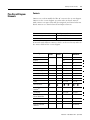
Drawing a Circuit with Pico
Pico Circuit Diagram
Elements
2-5
Contacts
Contacts are used to modify the flow of current in the circuit diagram.
Contacts in the circuit diagram are either make or break contacts.
Make contacts are open when off (de-energized) and closed when on.
Break contacts are closed when off and open when on.
Contact
Pico Representation
Make contact; Open when off
I, Q, M, A, C, T, P, D, S, :, R
Break contact; Closed when off
I, Q, M, A, C, T, P, D, S, R
Pico works with different contacts, which can be used in any order in
the contact fields of the circuit diagram.
Contact Type
Make
Contact
Break
Contact
1760-L12xxx
1760-L18xxx
1760-L20xxx
Controller Inputs
I
I
I1 to I8
I1 to I12
0 signal
I13
I13
Expansion Status
–
I14(3)
Short-circuit/overload
I16
I15 to I16
Soft Inputs - Keypad
P
P
P1 to P4
P1 to P4
Controller Outputs
Q
Q
Q1 to Q4
Q1 to Q8
Internal Marker Bits
M
M
M1 to M16
M1 to M16
Internal Marker Bits
N
N
N1 to N16
N1 to N16
Counters
C
C
C1 to C16
C1 to C16
Timers
T
T
T1 to T16
T1 to T16
Real Time Clock(1)
1 to
8
1 to
8
Analog Setpoint
Compare(2)
A
A
A1 to A16
A1 to A16
Text Display
D
D
D1 to D16
D1 to D16
Expansion Outputs or
Internal Marker Bits
S
S
S1 to S8
S1 to S8
Jump to Label
:
–
:1 to :8
:1 to :8
Expansion Inputs
R
R
–
R1 to R12
Expansion Overload
Detection
R
R
–
R15 and R16(3)
Publication 1760-GR001C-EN-P - April 2005
2-6
Drawing a Circuit with Pico
Contact Type
Make
Contact
Break
Contact
1760-L12xxx
1760-L18xxx
1760-L20xxx
Operating Hours Counter
O
O
O1 to O4
O1 to O4
Year Time Switch
Y
Y
Y1 to Y8
Y1 to Y8
Master Reset
Z
Z
Z1 to Z3
Z1 to Z3
(1) Not available on “-NC” models.
(2) This applies only to the 1760-LxxBWB-xx and 1760-L12DWD.
(3) This applies only to 1760-L18xxx-EX models. R15 and R16 are used for expansion overload detection for the
transistor expansion module, 1760-IB12XOB8, as described on page 9-4.
Relays
Pico has thirteen different types of relay for use in a circuit diagram.
Relay type
Pico Symbol 1760-L12xxx
1760-L18xxx
1760-L20xxx
Coil
Function
Parameter
Controller Outputs
Q
Q1 to Q8
Q1 to Q8
X
–
Internal Marker Bits
M
M1 to M16
M1 to M16
X
–
Internal Marker Bits
N
N1 to N16
N1 to N16
X
–
Counters
C
C1 to C16
C1 to C16
X
X
T
T1 to T16
T1 to T16
X
X
–
X
Timers
(1)
Real Time Clock
1 to
8
1 to
8
Operating Hours Counters
O
O1 to O4
O1 to O4
X
X
Analog Setpoint Compare(2)
A
A1 to A16
A1 to A16
–
X
Text Display
D
D1 to D16
D1 to D16
X
X
Jump to Label
:
:1 to :8
:1 to :8
X
–
Expansion Outputs or Internal Marker
Bits
S
S1 to S8 (as marker) S1 to S8
X
–
Year Time Switch
Y
Y1 to Y8
Y1 to Y8
–
X
Master Reset
Z
Z1 to Z3
Z1 to Z3
X
–
(1) Not available on “-NC” models.
(2) This applies only to the 1760-LxxBWB-xx and 1760-L12DWD.
The switching behavior of these relays is set using coil functions and
parameters. The coil functions and parameters are listed with the
description of each function relay type.
Publication 1760-GR001C-EN-P - April 2005
Drawing a Circuit with Pico
2-7
The options for setting output and marker relays are listed with the
description of each coil function.
Retentive Actual Values
With Pico 1760-L12BWB-xx, 1760-L12DWD, and 1760-L18xxx, it is
possible to save the actual values of markers, timers and counters in
the event of a power failure. The quantities and values that may be
retained are found in the following table.
For further information see the Pico Controller User Manual,
publication number 1760-UM001B-EN-P.
Retentive Relays
Relay Type
Pico
Symbol
1760-L12BWB-xx
1760-L12DWD
1760-L18xxx
Internal Marker Bits
M
4 (M13 to M16)
4 (M13 to M16)
Counters
C
1 (C8)
4 (C5, C6, C7, C8)
Timers
T
1 (T8)
2 (T7, T8)
Text Display
D
–
8 (D1 to D8)
Publication 1760-GR001C-EN-P - April 2005
2-8
Drawing a Circuit with Pico
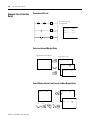
Basic Output Energize
{
On
Instruction
On
Output
Maintained/Flip-Flop Output
On
Instruction
On
Output
S,R
Set Instruction
Latching Output
On
On
Reset Instruction
Output
Publication 1760-GR001C-EN-P - April 2005
On
Drawing a Circuit with Pico
2-9
Example: Creating a Circuit Interconnect Contacts and Relays
Diagram
Connecting Pico
CR1
S1
S2
1. Connect S1 to Pico input terminal I1
Pico circuit diagram
2. Connect S2 to Pico input I2
I1-I2----{Q1
M1
3. Connect load M1 to Pico output Q1
CR1
Draw Circuit in Circuit Diagram Menu
Start Status Display
I 12 3 4 5 6 7 8
1 ...5 ..8 ....
MO
14:15
Q1234
12-I/O Pico
STOP
RE
or
MO
I
02:00
Ok
P
PROGRAM...
RUN
ST
PROGRAM...
.2 ..5 ..8
RUN
Ok
DELETE PROG
18-I/O Pico
Ok
Insert Contact “I1”
Circuit Diagram Display
Ok
Ok
I1
I1
I1
Ok
Publication 1760-GR001C-EN-P - April 2005
2-10
Drawing a Circuit with Pico
Insert Contact “I2”
I1
Ok
I1
I1
I1
I1
Ok
I1
I1
I2
I2
Ok
Draw Connection Between Contact and Relay Coil
I1-I2
I1-I2
Alt
I1-I2---
I1-I2---
Choose Relay Coil “Q1”
I1-I2---
Ok
I1-I2------{Q1
I1-I2------{Q1
Ok
I1-I2------{Q1
Ok
Publication 1760-GR001C-EN-P - April 2005
Drawing a Circuit with Pico
2-11
Change Operating Mode
I1-I1----{Q1
Esc
PROGRAM
DELETE PROG
PROGRAM...
Esc
RUN
PROGRAM...
RUN
PARAMETER
Ok
SET CLOCK..
Pico now in RUN mode
Test Circuit Diagram
PROGRAM...
STOP
PROGRAM...
STOP
PARAMETER
PARAMETER
SET CLOCK...
SET CLOCK...
Power flow display
I1-I2----{Q1
Ok
Publication 1760-GR001C-EN-P - April 2005
2-12
Drawing a Circuit with Pico
Operate Switch “S1” and “S2”
“S1” on
I1-I2----{Q1
I1-I2----{Q1
“S2” on
I1-I2----{Q1
Relay “Q1” picks up
Return to Status Display with ESC
12............
I 12 3 4 5 6 7 8
I1-I2----{Q1
Esc
MO
RE
or
13:34
Esc
Q1234
MO
I
02:00
P
ST
1.........RUN
STOP
12-I/O Pico
18-I/O Pico
In the next example, a timing relay will be added to the circuit.
Status display is activated.
Choose STOP mode.
Ok
Ok
PROGRAM...
RUN
PARAMETER
SET CLOCK..
Publication 1760-GR001C-EN-P - April 2005
Drawing a Circuit with Pico
2-13
Function Relay Types
Circuit Diagram
Symbol
Function Relay Type
Timing relay with on-delay, with and without random switching
Timing relay with off-delay, with and without random switching
Timing relay, single pulse
Timing relay, flashing
Counter relay, up/down counter
Time switch, weekday/time (only in Pico models with clock)
Analog comparator relay (only in Pico models with 24V dc)
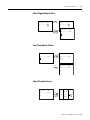
Timing Relay
X ?X
Timing Relay with on delay, with and
without random switching
on
Trigger
Reset
on
on
Timer Output
t
t
t
Publication 1760-GR001C-EN-P - April 2005
2-14
Drawing a Circuit with Pico
Timing Relay with Off-Delay, with and without
Random Switching
?
on
Trigger
on
Reset
on
Timer Output
t
t
With random switching, the relay contact switches randomly at any
time up to the specified time value (shown shaded in figure).
Timing Relay, Single Pulse
Trigger
on
on
Reset
Output
on
t
Publication 1760-GR001C-EN-P - April 2005
t
Drawing a Circuit with Pico
2-15
Timing Relay, Flashing
Flash Frequency = 1/2 x setpoint
on
Trigger
on
Reset
on
Timer Output
t
t
t
Parameter Display for Timing Relays
Switch Function
00.00
Accumulated Time
Setpoint
Time Units
S
30.00
Trigger (Connected)
{
TRG
RES
Reset (Not Connected)
T1
+
Timer Number
Parameter Display
(Access Control)
Publication 1760-GR001C-EN-P - April 2005
2-16
Drawing a Circuit with Pico
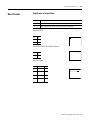
Counter Relay
on
Count Input
on
Direction
Reset
Accumulated Value
(setpoint = 6)
Counter Output
on
8
6
4
2
0
7
5
3
1
on
Parameter Display for Counter Relays
Counter Number
Setpoint
C1 N
S
+
AAAAA
Parameter Display
(Access Control)
Accumulated Value
Publication 1760-GR001C-EN-P - April 2005
Drawing a Circuit with Pico
2-17
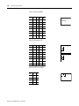
Real Time Switch
Example: Real Time Switch 1 switches on Monday through Friday
between 6:30 and 9:00 and again between 17:00 and 22:30 (5:00 pm
and 10:30 pm).
+
1A
D
ON
OFF
+
1B
MO-FR
06:30
09:00
D
ON
OFF
MO-FR
17:00
22:30
on
on
on
Parameter Display for Real Time Switches
Real Time Switch Number
Week Day(s) from - to
1 A
D
+
Parameter Display
(Access Control)
SU
On Time
ON
Off Time
OFF --:--
--:--
Publication 1760-GR001C-EN-P - April 2005
2-18
Drawing a Circuit with Pico
Analog Comparator
Available functions:
• I7 ≥ I8, I7 ≤I8
• I7 ≥ Setpoint, I7 ≤Setpoint
• I8 ≥ Setpoint, I8 ≤Setpoint
The analog comparator can compare voltages from 0V to 10V
(setpoints “0.0” to “10.0”).
Analog signals of sensors typically fluctuate by
several millivolts. For stable switching the setpoints
should differ by at least 0.2V (switching hysteresis).
Do not use any relay with output energize or
impulse relay coil functions.
TIP
Parameter Displays for Analog Comparators
Compare inputs I7 and I8.
Input I7
I7
ANALOG
8.0 V
Compare Function
Input I8
Current Value
A1
I8
4.2 V
+
Analog Compare Number
Parameter Display
(Access Control)
Current Value
Compare input “I7” to a setpoint.
Input I7/I8
I7
Compare Function
Setpoint
Publication 1760-GR001C-EN-P - April 2005
ANALOG
8.0 V
Current Value
A1
3.2
+
Relay Number
Parameter Display
(Access Control)
Drawing a Circuit with Pico
2-19
Text Display
The Text Display is used to display eight freely definable messages on
the Pico screen. Each text block displays up to 48 characters from the
Pico display character set (ASCII + Pico special characters). If the Text
Display is enabled, the text entered via PicoSoft is displayed. If several
Text Displays are enabled, the next screen is displayed every 4
seconds. When Text Display D1 is enabled it stays displayed (fault
indication).
Press Ok to switch to the menus at any time.
Current values or parameters of function relays can be displayed in
lines 2 and 3.
Examples:
Fault Signals
Time with Text Display
CAUTION!
THE TIME
PUMP 1
IS
MOTOR
14:42
MALFUNCTION
Display Counter Value
Display Current Value and
Parameter of Timing Relay
QUANTITY
TIME RELAY
ACTV
SETP99.00 S
0042
PCS
1
ACTV 42.00 S
SETP0100
Publication 1760-GR001C-EN-P - April 2005
2-20
Drawing a Circuit with Pico
Example: Use a Function
Relay
Conventional Circuit
Pico switches M1 with
10 seconds delay.
CR1
S1
S2
I1-I2----{M1
M1-------TT1
T1-------{Q1
T1
10.0 sec
CR1
T1
M1
Pico Circuit Diagram
Select an Internal Marker Relay
Start Circuit from first example
Position cursor on “Q”
I1-I2----{Q1
Ok
I1-I2----{Q1
I1-I2----{M1
2X
I1-I2----{M1
Ok
Select Marker Contact and Connect to New Output Relay
I1-I2----{M1
Ok
I1-I2----{M1
I1
I1-I2----{M1
M1------ {Q1
2X
2X
Ok
Publication 1760-GR001C-EN-P - April 2005
3X
Alt
Ok
Drawing a Circuit with Pico
2-21
Select Trigger Relay for Time
I1-I2----{M1
I1-I2----{M1
M1-------{Q1
M1-------TT1
I1-I2----{M1
2X
Ok
M1-------TT1
Insert Timing Relay Contact
I1-I2----{M1
I1-I2----{M1
M1-------TT1
Ok
2X
M1-------TT1
I1
I1-I2----{M1
M1-------TT1
T1
Select Parameter Access
I1-I2----{M1
M1-------TT1
T1
2X
Ok
X
S
00.00
{
TRG
T1
RES
+
Publication 1760-GR001C-EN-P - April 2005
2-22
Drawing a Circuit with Pico
Set “10 Seconds”
T1
S
+
X
T1
00.00
+
X
S
00.00
TRG
TRG
RES
RES
2X
T1
S
+
X
10.00
TRG
RES
2X
back to circuit diagram
Ok
Connect Timing Relay Contact to New Output Relay
I1-I2----{M1
M1-------TT1
T1
Alt
I1-I2----{M1
M1-------TT1
T1
3X
I1-I2----{M1
3X
M1-------TT1
Ok
T1-------{Q1
Change Pico to RUN to test the program. Test the circuit as shown for
the first example. To display and access the parameters for the timing
relay and change the time value in RUN mode, position the cursor in
the circuit diagram on the “T” of “T1” and press Ok.
Publication 1760-GR001C-EN-P - April 2005
Drawing a Circuit with Pico
Basic Circuits
2-23
Significance of Logic Values
Value
Function
“0”
Make contact open, break contact closed, relay coil not energized
“1”
Make contact closed, break contact open, relay coil energized
Negation (NOR)
I1
Q1
1
0
0
1
I1---------{Q1
Permanent Contact (Unconditional Rung)
---
Q1
1
1
-----------{Q1
Flip-Flop Output
I1
State Q1
Q1
0
0
0
0 to
1
0
1
0
1
1
0 to
1
1
0
I1--------- Q1
Publication 1760-GR001C-EN-P - April 2005
2-24
Drawing a Circuit with Pico
Series Connection (AND)
I1
I2
I3
Q1
Q2
0
0
0
0
1
1
0
0
0
0
0
1
0
0
0
1
1
0
0
0
0
0
1
0
0
1
0
1
0
0
0
1
1
0
0
1
1
1
1
0
I1-I2-I3-{Q1
I1-I2-I3-{Q2
Parallel Connection (OR)
I1
I2
I3
Q1
Q2
I1--------{Q1
0
0
0
0
1
I2
1
0
0
1
1
I3
0
1
0
1
1
1
1
0
1
1
I1--------{Q2
0
0
1
1
1
I2
1
0
1
1
1
I3
0
1
1
1
1
1
1
1
1
0
Exclusive OR Circuit (XOR)
Publication 1760-GR001C-EN-P - April 2005
I1
I2
Q1
I1-I2------{Q1
0
0
0
I1-I2
1
0
1
0
1
1
1
1
0
Drawing a Circuit with Pico
2-25
Motor Start/Stop Circuit
I1
I2
Contact
Q1
Coil
Q1
0
0
0
0
1
0
1
1
0
0
1
1
0
1
0
0
1
1
0
0
I1--I2-----{Q1
Q1
Alternatively:
I1--------SQ1
I2--------RQ1
Publication 1760-GR001C-EN-P - April 2005
2-26
Drawing a Circuit with Pico
Publication 1760-GR001C-EN-P - April 2005
Chapter
3
Pico Interface Socket
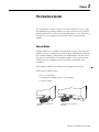
The Pico interface socket, which is beneath a protective cap, accepts
the optional Pico memory module, or connects Pico to a PC using the
optional PC interface cable and the PicoSoft software. This allows you
to copy the circuit diagrams to and from the PC and/or memory
module.
Memory Module
Memory modules are available as an optional accessory. Each memory
module can store a single Pico circuit diagram. Information stored on
the memory module is non-volatile (the information is not lost when
the power is turned off). The memory module can be used to make a
backup copy of a program and/or to transfer it to another Pico
controller.
Each memory module can hold one Pico program, up to 32K.
Each memory module stores:
• the circuit diagram
• all parameter settings of the circuit diagram
• system settings
1760-MM1 for all 1760-L12xxx
controllers
1
1760-MM2 for the 1760-L18xxx
controllers
Publication 1760-GR001C-EN-P - April 2005
3-2
Pico Interface Socket
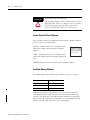
ATTENTION
ELECTRICAL SHOCK HAZARD
The memory module and PC-cable socket are at the
potential of L2. There is a danger of electric shock if
L2 is not grounded. Do not make contact with
electrical components under the socket cover.
Load or Store the Circuit Diagram
You can only transfer the program from Pico to the memory module
or vice versa in the STOP mode.
DEVICE - CARD: Transfer circuit diagram and
parameter settings from Pico to the memory
module.
DEVICE ->
CARD ->
CARD
DEVICE
DELETE CARD
CARD - DEVICE: Transfer circuit diagram and
parameter settings from the memory module to
Pico.
DELETE CARD: Delete the contents of the memory module.
Available Memory Modules
The following memory modules are available as Pico accessories.
Pico Controller
Memory Module
1760-L12xxx
1760-MM1 (Series A only)
1760-L18xxx
1760-MM2 (Series A only)
Series B Pico Controllers
1760-MM2B
Programs including all relevant data can be transferred from the
1760-MM2B memory module to the Series B Pico Controllers. The
existing 1760-MM1 and 1760-MM2 memory modules are Read-Only
when used with Series B Pico Controllers. The 1760-MM2B memory
module will not work with Series A Pico Controllers.
Publication 1760-GR001C-EN-P - April 2005
Pico Interface Socket
3-3
PicoSoft
PicoSoft is an optional PC program that creates, stores, and manages
Pico circuit diagrams. It transfers the circuit diagrams from the PC to
Pico or vice versa using a special PC interface cable.
ATTENTION
The PC interface cable is catalog number
1760-CBL-PM02 and is available as an accessory
item. Only use the Pico interface cable. Do not
attempt to make your own cable as this can cause
damage to the unit or present a shock hazard.
The PicoSoft software also includes extensive on-line Help.
To use the on-line Help, start PicoSoft and choose Contents in the
Help menu. Context sensitive help is also available. Choose a menu
item with the mouse and press F1 while keeping the mouse button
pressed.
Software Compatibility
If you are using programming software to program the Pico controller,
be sure that you are using the correct software version.
IMPORTANT
PicoSoft version 6.1 or higher must be used to for the
Series B Pico controller. Earlier versions of PicoSoft
can only be used with Series A Pico controllers.
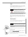
Find the Series Letter
The Series letter is printed on the side of the housing as shown.
Download the Software
You can download a free copy of PicoSoft version 6.1 from our web
site. Go to http://www.ab.com/picosoft6.
For PicoSoft Pro, please contact your Allen-Bradley Distributor or
Rockwell Automation representative.
Publication 1760-GR001C-EN-P - April 2005
3-4
Pico Interface Socket
Publication 1760-GR001C-EN-P - April 2005
Appendix
A
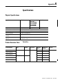
Specifications
Physical Specifications
Specification
1760-L12xxx
1760-L18xxx,
1760-L20xx
1760-IA12XOW6I,
1760-IA12XOW4I
1760-IB12XOB8
1760-IB12XOB8
1760-OW2
Weight
200g (7 oz)
300g (10.6 oz)
70g (0.154 lb)
Ambient temperature, (operation)
-25°C to + 55°C (-18°F to 131°F)
Storage Temperature
-40°C to +70°C (-40°F to +158°F)
Operating Humidity
5 to 95%, non-condensing
Emitted interference, interference
immunity
EN 55011, EN 55022, Class B
Standards and regulations
Approvals
EN 50178
UL, CSA, CE, C-Tick
Product Selection Table
Controllers
Catalog Number
Inputs
Outputs
Line Power
Real Time
Clock
Display and
Keypad
Analog
1760-L12AWA
8 (120/240V ac)
4 (relay)
100 - 240V ac
Yes
Yes
No
1760-L12AWA-NC(1)
No
Yes
1760-L12AWA-ND(2)
Yes
No
Yes
Yes
1760-L18AWA-EX(3)
Yes
Yes
1760-L18AWA-EXND(2)(3)
Yes
No
1760-L18AWA
1
12 (120/240V ac)
6 (relay)
Publication 1760-GR001C-EN-P - April 2005
A-2
Specifications
Catalog Number
Inputs
Outputs
Line Power
Real Time
Clock
Display and
Keypad
Analog
1760-L12BWB
8 (24V dc)
4 (relay)
24V dc
2 (0 to 10V dc)
Yes
Yes
1760-L12BWB-NC(1)
No
Yes
1760-L12BWB-ND(2)
Yes
No
Yes
Yes
Yes
No
Yes
Yes
Yes
No
Yes
Yes
Yes
No
Yes
Yes
1760-L12BBB
4 (MOSFET)
1760-L12BBB-ND
1760-L12NWA
8 (24V ac)
4 (relay)
24V ac
1760-L12NWA-ND
1760-L12DWD
8 (12V dc)
12V dc
1760-L12DWD-ND
1760-L18BWB-EX(3)
12 (24V dc)
6 (relay)
24V dc
2 (0 to 10V dc)
1760-L18BWB-EXND(2)(3)
6 (relay)
Yes
No
2 (0 to 10V dc)
1760-L20BBB-EX(3)
8 (MOSFET)
Yes
Yes
4 (0 to 10V dc)
1760-L20BBB-EXND(2)(3)
8 (MOSFET)
Yes
No
6 (relay)
12V dc
Yes
Yes
6 (relay)
12V dc
Yes
No
12 (24V ac)
6 (relay)
24V ac
Yes
Yes
1760-L18NWA-EXND(2)(3) 12 (24V ac)
6 (relay)
Yes
No
1760-L18DWD-EX(3)
12 (12V dc)
1760-L18DWD-EXND(2)(3)
1760-L18NWA-EX(3)
(1) NC = no real time clock
(2) ND = no display
(3) EX = suitable for use with expansion modules
Publication 1760-GR001C-EN-P - April 2005
4 (0 to 10V dc)
Specifications
A-3
Expansion Modules
Catalog Number
Inputs
Outputs
Line Power
1760-IA12XOW6I
12 (100 - 240V ac)
6 (relay)
100 - 240V ac
1760-IA12XOW4IF
12 (100 - 240V ac)
4 (relay)
100 - 240V ac
1760-IB12XOW6I
12 (24V dc)
6 (relay)
24V dc
1760-IB12XOB8
12 (24V dc)
8 (transistor)
24V dc
1760-OW2
-
2 (relay)
24V dc
Accessories
Catalog Number
Description
1760-MM1
Memory Module for 12 I/O Pico Controller
1760-MM2
Memory Module for 18 I/O Pico Controller
1760-MM2B
Memory Module for Pico Series B Controllers
1760-CBL-PM02
Programming Cable for Pico Controller
1760-RPLCONN
Expansion Module Connector - included with expansion module. Catalog number listed is replacement part.
1760-SIM
Input Simulator for 12 I/O 24V dc Pico Controller
1760-PICOSOFT
Configuration Software for Pico Controllers.
D1760GR001BENP
Pico Controllers Getting Results Manual, publication number 1760-GR001B-EN-P
D1760UM001BENP
Pico Controllers User Manual, publication number 1760-UM001B-EN-P
Publication 1760-GR001C-EN-P - April 2005
A-4
Specifications
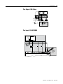
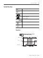
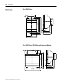
Dimensions
Pico 1760-L12xxx
50 1.97"
110 4.33"
90 3.54"
102 4.02"
45 1.77"
10.75
0.423"
4.5 0.177"
47.5 1.87"
56.5 2.22"
58 2.28"
M4
35.75 1.41"
71.5 2.81"
Pico 1760-L18xxx, 1760-L20xxx and Expansion Modules
16.25
0.640"
75 2.96"
16.25
0.640"
110 4.33"
102 4.02"
90 3.54"
45 1.77"
M4
4.5 0.177"
47.5 1.87"
56.5 2.22"
58 2.28"
107.5 4.23"
Publication 1760-GR001C-EN-P - April 2005
Specifications
A-5
Pico 1760-OW2 Expansion Module
110 4.33"
90 3.54"
102 4.01"
7.5 0.295"
M4
7.5 0.295"
35.5 1.4"
Dimensions of the 1760-RM… Remote Processor modules
1760-DU… and 176-RM…
58
2.28"
176-RM…
22.5
0.89"
30 1.18"
75
2.95"
22.5
0.89"
36.2
1.43"
20.5
0.81"
43.2
1.7"
27.5
1.08"
Publication 1760-GR001C-EN-P - April 2005
A-6
Specifications
Publication 1760-GR001C-EN-P - April 2005
Index
A
accessories A-3
Allen-Bradley
contacting for assistance Preface-iii
support Preface-iii
Analog comparator 2-18
B
Basic circuit
Exclusive OR circuit (XOR) 2-24
Flip-flop output 2-23
Impulse relay 2-23
Motor start/stop circuit 2-25
Negation (NOR) 2-23
Permanent contact 2-23
Series connection (AND) 2-24
Break contact 2-5
Buttons 1-10
Use in circuit diagrams 2-1
C
Cable 3-3
Change operating mode 2-4
Circuit diagram
Access relay parameters 2-21
Choosing relay type 2-10
Displaying 2-9
Example 2-9, 2-20
Inserting contacts 2-9
Loading 3-2
Select marker relay 2-20
Storing 3-2
Symbols 1-14
Testing 2-11
Using a function relay 2-20
Using buttons in 2-1
Circuit diagram elements 2-5
Coil function 2-8
common techniques used in this manual
dimensions
1760-L12 A-4
1760-L18 A-4
1760-L20 A-4
1760-OW2 A-5
1760-RM A-5
expansion modules A-4
E
Example
Basic circuits 2-23
Circuit diagram 2-9
Contacts and relays 2-9
Example of function relay 2-20
F
Function relays
Analog comparator 2-18
Counter relay 2-16
Overview 2-13
Text display 2-19
Time switch 2-17
Timing relay 2-13
K
Keypad 1-10
L
Logic tables 2-23
M
Make contact 2-5
manuals, related Preface-ii
Memory Module (optional) 3-1
Menu guidance 1-11
Menu structure 1-15
Mounting 1-3
Preface-ii
contacting Allen-Bradley for assistance
Preface-iii
Contactor function 2-8
Contacts
Overview 2-5
Counter relay 2-16
Parameter display 2-16
Cursor display 1-13
D
O
Operating buttons 1-10
P
Parameter display
Analog comparator 2-18
Counter relay 2-16
For timing relays 2-15
Time switch 2-17
Publication 1760-GR001C-EN-P - April 2005
2
Index
physical specifications A-1
Overview of Pico 1-2
PicoSoft 3-3
Programming cable 3-3
publications, related Preface-ii
Purpose of this Manual Preface-ii
R
related publications Preface-ii
Relay types
Overview 2-6
Symbols in circuit diagram 1-14
System menu 1-18
T
Terminals, inputs/outputs 1-4
Text display 2-19
Time switch 2-17
Parameter display 2-17
Timing relays 2-13
Parameter display 2-15
troubleshooting
contacting Allen-Bradley for assistance
Preface-iii
S
selection table
controllers A-1
selections table
expansion modules A-3
Setting the time 2-3
Setting week day 2-3
Software 3-3
specifications
physical A-1
Startup behavior 2-4
Status display 1-12
Summer time 2-4
Publication 1760-GR001C-EN-P - April 2005
W
Winter time 2-4
Wiring diagrams
1760-L12AWA-NC, 1760-L12AWA, and
1760-L12AWA-ND 1-4
1760-L12AWA-xx and 1760-L12BWB-xx
1-5
1760-L12BWB and 1760-L12BWB-NC
1-4
1760-L18AWA 1-9
1760-OW2 1-9
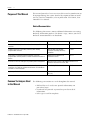
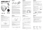
Rockwell Automation
Support
Rockwell Automation provides technical information on the web to assist you
in using our products. At http://support.rockwellautomation.com, you can
find technical manuals, a knowledge base of FAQs, technical and application
notes, sample code and links to software service packs, and a MySupport
feature that you can customize to make the best use of these tools.
For an additional level of technical phone support for installation,
configuration and troubleshooting, we offer TechConnect Support programs.
For more information, contact your local distributor or Rockwell Automation
representative, or visit http://support.rockwellautomation.com.
Installation Assistance
If you experience a problem with a hardware module within the first 24
hours of installation, please review the information that's contained in this
manual. You can also contact a special Customer Support number for initial
help in getting your module up and running:
United States
1.440.646.3223
Monday – Friday, 8am – 5pm EST
Outside United
States
Please contact your local Rockwell Automation representative for any
technical support issues.
New Product Satisfaction Return
Rockwell tests all of our products to ensure that they are fully operational
when shipped from the manufacturing facility. However, if your product is
not functioning and needs to be returned:
Publication 1760-GR001C-EN-P - April 2005 2
Supersedes Publication 1760-GR001B-EN-P - July 2001
United States
Contact your distributor. You must provide a Customer Support case
number (see phone number above to obtain one) to your distributor in
order to complete the return process.
Outside United
States
Please contact your local Rockwell Automation representative for
return procedure.
PN 40072-085-01(3)
Copyright © 2005 Rockwell Automation, Inc. All rights reserved. Printed in the U.S.A.