1
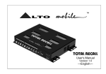
TM
LTO
ADP102
ADP152
User's Manual
Version 1.0
---English---
TM
LTO
Care & Safety Instructions
All the safety and operating instructions should be read before this product is installed and operated. We recommend
that installation be carried out by an authorized mobile electronics installation company. Please contact your local ALTO
Mobile distributor for a list of authorized installers in your area.
DO NOT DISASSEMBLE:
No user serviceable parts inside; refer servicing to qualified personnel only.
WATER & MOISTURE:
The equipment should be protected from moisture and rain, especially if mounted in the vehicle's trunk area or any location that may be susceptible to water ingress.
PRODUCT LOCATION:
The equipment should be situated so that its location does not interfere with safe driving of the vehicle. Avoid locations
close to safety air bags. Ensure proper ventilation. The product should not be situated under carpeting or in a totally
sealed enclosure. Partly enclosed equipment racks should be well ventilated, using forced air cooling fans if necessary.
Locate away from heat sources such as engine exhaust systems and coolant radiators.
POWER SOURCE & GROUNDING:
This product is designed only for vehicles with a 12 VOLT NEGATIVE GROUND electrical circuit. This product may be
damaged if used in vehicles with a 24 Volt supply or a positive ground electrical circuit.
ELECTRICAL CONNECTION:
Improper electrical wiring may invalidate the product warranty and/or the vehicle warranty. Installation should only be
undertaken by a qualified automotive electrician, preferably MECP qualified or local equivalent.
CARE & CLEANING:
Clean only with a dry cloth. Avoid sharp objects from making contact with the case.
SERVICING:
If a malfunction occurs, the equipment should be serviced only by qualified personnel. Return to the dealer who supplied
you with the unit.
Critical components should only be replaced with factory parts or recommended equivalents.
1
Introduction
TM
LTO
Dear Customer,
Thank you for choosing this ALTO Mobile ADP Series Full-Range Class-D Power Amplifier. We hope you will enjoy using
this product as much as we enjoyed developing it. The ADP Series is the result of considerable research and development
in our R&D centers in Europe and the Far East. It is a very close cousin of ALTO's professional Class-D amplifier models.
We've been designing products for musicians and recording studios for a long time, so the car audio product you now
have in your hands has an unusually fine pedigree.
You have purchased a technologically advanced and powerful amplifier. Don't let its size fool you. Its very high efficiency
means that, unlike a conventional Class-AB amplifier, it doesn't require a large, heavy heatsink to dissipate heat. Instead,
far more of the power going in is sent out in the form of acoustic power to drive your speakers. If your new ADP power
amp used conventional circuitry, it would be at least three times the size and four or five times heavier. So you could say
it really is a 'little monster' of an amp!
If you have not had your new amplifier installed in your vehicle, that is obviously the first thing you will need to do. We
strongly recommend that you have the unit professionally installed by a specialist company authorized by the ALTO Mobile
distributor in your country. The installation instructions in this manual are not intended to be a thorough explanation of
all the steps involved in correctly fitting this unit. The instructions assume that the person installing the equipment has
been trained to carry out such work.
You are an important member of our team. We listen to what our customers say and take on board their suggestions. It
is this feedback that helps us create the products you want. So if you have any comments, please let us know via email
to "[email protected]".
THE ALTO MOBILE TEAM
2
TM
Drawings Showing the Front and Rear Panels
LTO
INPUT
CH1
OUTPUT
CH2
CH1
POWER INPUT
CH2
REM GND
1
2
GAIN
CH 1. 2
5
FREQ.
3
FUSE
12V
4
HP/FLAT/LP
CH 1. 2
6
3
Installation & Setup Instructions
TM
LTO
Mounting the Unit
Your ADP Series Power Amplifier has two fixing 'ears' at each side, allowing it to be firmly screwed to a suitable surface.
It may be mounted vertically or horizontally, but avoid mounting the unit upside down (suspended from a shelf, for example)
since this may affect efficient heat dissipation. Do not mount the unit under carpeting or within a small sealed enclosure,
as this will prevent proper ventilation. Take care not to mount the unit where it may become wet or subject to damage
from items placed in the trunk area.
1 Signal Inputs
The Left and Right Channel input terminals are standard unbalanced phono type sockets. Connect the low-level preamplifier output cables from your car radio/cassette player, CD/receiver or other device (active crossover network or
ALTO Mobile digital processor, for example) to the Input terminals of your ADP amplifier.
2 Speaker Outputs
Connect suitable cables (not supplied) from the Output terminals of your ADP amplifier to your speaker inputs, taking
care to ensure correct + / - polarity. Use the correct size Allen Key to tighten the screws of the speaker terminals.
IMPORTANT
The amplifier must not be run with any of its output channels open (i.e. not connected to a speaker).
Running the amplifier in this way for even a short time can cause permanent damage.
3 Power, Ground and Remote Switch-On Terminals
Caution: Before making any connections, you should disconnect power from the battery to avoid accidental short-circuits.
The conventional way is to disconnect the Negative terminal of the battery, but beware - this action will disconnect power
from all electrical items in the vehicle, including:
a. the cassette or CD player (which may require a code number to reactivate it. Do you know the code?)
b. the security system (which may trigger and sound an alarm from its back-up battery. Do you know how to override the
alarm system?)
c. Memory modules (which may suffer memory loss if disconnected for too long).
If you have any doubts, you should seek professional assistance.
4
TM
LTO
Installation & Setup Instructions
You will find a Power Input terminal block at the far end of the side panel. There are three connections to be made:
+12V
The terminal marked +12V should be connected to a permanent (i.e. not ignition switched) positive 12 Volt supply from
the vehicle battery.
GND
The terminal marked GND (Ground) should be connected to a cable which is terminated to the vehicle chassis.
Ensure that the point where this cable attaches to the vehicle chassis provides good electrical contact. It may be necessary to rub away paintwork to expose the metal at this point. In this case, after making a firm screw connection of
the ground cable to the chassis, paint over the terminal point to protect the metal from corrosion.
To avoid noise problems, ensure that this point on the vehicle chassis measures as a true ground reference. You will
need a multimeter to check that there is no (or very minimal) resistance (in ohms) between the battery negative post
and the point you have chosen on the chassis.
If drilling a new ground point, check that there is nothing behind the panel you are about to drill, such as the fuel tank!
Where a ground point already exists (for an existing power amplifier, for example) it is generally best practice to ground
the ADP amplifier and any other system components to this same point on the vehicle chassis (a practice known as
Star Grounding). This helps ensure that the ground reference is the same for all components, thus avoiding the chance
of automotive noise.
REM
The terminal marked REM (remote) accepts a +12V switched input from the source unit (Cassette or CD player). When
the source unit is switched on, a pulse is sent down this line. The amplifier senses this pulse and switches itself on.
The source unit should be equipped with a suitable Remote Switch cable - check the instruction book supplied with your
Tape or CD player.
If the Remote output from the source unit is already being used to switch on another unit that is close to your ADP
amplifier, it is usually possible to 'daisy-chain' a cable from the Remote terminal on that unit to the REM terminal of the
ADP amplifier. This avoids the need to run a separate cable from the source unit.
5
Installation & Setup Instructions
TM
LTO
Use the correct size Allen Key to tighten the terminal screws. Before reconnecting power to the circuit, double check all
connections are correct and ensure there are no stray strands of wire which could touch the chassis of the ADP amplifier
or any of the other terminals.
The power-on LED next to the power input terminal block will light to show the unit is receiving power. This is a 2 colour
LED. Green means that all is working correctly. Red means there is a problem (low voltage, high temperature, short circuit
etc.).
4 Fuse
The unit is protected by a panel-mounted fuse (standard automotive type). If it becomes necessary to replace the fuse,
use only the same type and value as originally fitted (25A or 30A fuse).
5 Input Gain Control
Use this control to match the pre-amp output level of your car audio source unit (tape or CD player) to the input stage of
the ADP amplifier. The amplifier's input gain is variable from 400mV (MAX Gain) to over 15V (MIN Gain).
Here are two different ways of setting up the input gain:
The easy (but less accurate) way is to turn the gain control on your ADP amplifier fully counter-clockwise to its MIN
(minimum gain) position, and then turn the volume control on your CD player to about 75%. Now play some music
and increase the gain on the ADP amplifier towards MAX until you arrive at your maximum preferred listening level,
or when the speakers begin to sound stressed. At this point, either the signal is clipping (i.e. exceeding its maximum
level before distortion) or you have reached the mechanical limits of the speakers. So just back down the gain control
a little and you should be set.
The better way is to use a sine wave test tone (you'll find these on several test CDs) and an oscilloscope to check what
is the maximum clean output level from the source unit (i.e. your CD player etc.). Use a tone that is appropriate for the
speaker driver you are testing. For example, 60Hz for subs, 1KHz for mids or 8KHz for tweeters, and about 1KHz for
full-range speakers and component kits. Connect your oscilloscope probes across the +/ - terminals of the speaker
connected to your amplifier. Be sure to set the scope's input to AC. You may need to use a resistive network to reduce
the level of the signal being fed to your scope. Start with the amp gain set to about 25% and the volume control on
your source unit set low, then gradually turn up the volume (on the source unit) using the appropriate test tone track.
6
TM
LTO
Installation & Setup Instructions
See how far you can take the volume control before the signal begins to clip (you may need to reduce the amp gain if
it gets too loud). If you see it clip on the scope, back off the volume control a little. Now increase the gain on the amp
until you find the highest level before distortion or visible clipping. Bear in mind that the maximum level may be limited
by your speakers - don't over-drive them.
6 Low-Pass & High-Pass Filters
You are able to select either a low-pass or high-pass filter, or switch all filters out (FLAT position). Both filters have a cut
-off point that is variable from 50Hz to 500Hz.
When selecting the Low-Pass (LP) filter, the level of frequencies ABOVE the selected cut-off point will be reduced at
the rate of 12dB per octave. This is typically used to prevent woofers from attempting to reproduce mid and upper
frequencies.
When selecting the High-Pass (HP) filter, the level of frequencies BELOW the selected cut-off point will be reduced at
the rate of 12dB per octave. This is used to prevent low frequencies from being delivered to midrange drivers, which
could damage the speaker.
When in the FLAT position, the full audio band is allowed to pass and the setting of the variable FREQ control has no
effect.
Bridged Mode
Your ADP amplifier has been designed to be used in stereo 2-channel mode only, driving into a nominal impedance load
of 4 ohms per channel (minimum). Dedicated high power mono models are available in the ADP range and we do not
recommend that you drive your stereo model in bridged mono (single channel) mode, or in tri-mode. However, it is possible to operate your stereo amplifier in bridged mono mode as long as the overall speaker load is no less than 8 ohms.
Typically this would be achieved by wiring two 4 ohm speakers in series.
If you attempt to drive into an impedance load that is too low, the amplifier will cut into its protection mode. This is a designed reaction to safeguard the amplifier and does not indicate a fault with the product.
7
Brief Technical Overview
TM
LTO
Although commonly referred to as a "digital" amplifier, Class-D is more accurately described as a Pulse Width Modulated
(PWM) amplifier. A PWM amplifier converts the music (which is a complex arrangement of sine waves) into a series of
pulses. The major benefit of this design is its great efficiency, which is the relationship between the amount of audio output
power delivered to the speakers and the amount of power required from the vehicle's power supply. Around half the power
drawn from the power supply by a conventional amplifier is wasted as heat. With Class-D designs, the power wasted is
minimal by comparison, which means relatively low current consumption, low heat, better long-term reliability, small size
and valuable weight savings thanks to a much lighter, smaller heatsink.
The circuit operates by first creating a digital-type waveform from the standard analogue audio input. The width of each
of the pulses varies according to the amplitude of the original audio signal. This digital pulse train is then used to switch
MOSFET power output transistors at high speed, with the width and speed of the pulses determining the frequency and
amplitude of the audio output.
Some switching distortion is inevitable. Fortunately, the frequency of this distortion is linked to the frequency at which the
MOSFETs are switched, and so it is possible to design a circuit that switches so quickly that any noise produced is substantially above the highest audible frequency. It can then be isolated and removed using filters.
As well as requiring the switching to be at very high speed (something which has limited previous Class-D designs), a
sophisticated recombinant filter (this smoothes out the high speed pulses and puts them together to form sine waves
again) is required in order to deliver a truly audiophile sound. In the past this has required an elaborate network of capacitors and inductors, but this can now be achieved more efficiently using the latest integrated circuit technology. This,
along with a number of other inspired features of the circuit, has resulted in a full-range pure Class-D design that is unique
to ALTO Mobile in the field of car audio.
8
TM
LTO
Further Information
For additional information, please visit our website at www.altomobile.com, which includes a technical discussion forum
where users can exchange ideas.
Troubleshooting
Power LED not lit: Is the Remote switch cable from the source unit (Cassette or CD Player) attached to the REM terminal
of the ADP amplifier, and is the source unit switched on? Are the +12V and GND (Ground) terminals connected correctly?
Is the Ground cable properly attached to the chassis of the vehicle or to an existing ground point that is known to be OK?
Check the fuse and replace if blown (use only a fuse of the correct rating).
No Sound: Adjust the level of the ADP amplifier Input Gain Control. Are the Input signal cables correctly connected? If
there is only sound from one channel, swap the Left and Right channel Input cables at the amplifier inputs. If the fault
moves to the other channel then the fault is with a cable, or the source unit or other unit between the source unit and
amplifier (active crossover, for example). If the fault remains in the same speaker, check the speaker cable is connected
correctly. If it seems correct, swap the Left and Right Output (speaker) cables on the ADP amplifier. If the fault remains
in the same speaker then the problem may be with that speaker or the speaker cable. If the fault moves to the other
speaker then the amplifier may be faulty. Leave the unit installed in your system and return to your dealer so that they
can check it.
Distorted Sound or Low Volume: Adjust the Input Gain Control of the amplifier and, where applicable, the Output Level
Controls of any unit before the amplifier (such as an active crossover or ALTO Mobile digital signal processor). Check the
settings of the amplifier's on-board filter.
Music cuts out intermittently at high level: The amplifier is protecting itself, either because it is being over-driven or because the speaker impedance load is dropping too low. Reduce the volume level or adjust the amplifier Gain towards
MIN. Ensure that the overall nominal impedance of the connected speaker system is no less than 4 ohms (stereo mode).
9
R
Your ALTO Warranty
TM
LTO
To be protected by this warranty, the buyer must be able to produce a numbered, machine printed sales receipt from his
supplying dealer that clearly shows the dealer's name and address, the buyer's name and address, purchase date, model
and serial number of the product.
ALTO warrants the mechanical and electronic components of this product to be free of defects in material and workmanship for a period of one (1) year from the original date of purchase. If any defects occur within the specified warranty
period, in accordance with the warranty regulations described below, ALTO shall, at its sole discretion, either repair or
replace the product.
If the product needs to be modified or adapted in order to comply with local technical or safety standards, such modification/adaptation shall not be considered a defect in materials or workmanship.
Damages/defects caused by the following conditions are not covered by this warranty:
Defects to expendable parts (typically potentiometers, switches, terminals) caused by normal wear and tear.
Misuse, neglect or failure to install or operate the unit in compliance with the instructions given in the user or service
manuals.
Electrical/mechanical connection, operation or location of the unit in any way that does not comply with the technical
or safety regulations applicable in the country where the product is used.
Damages/defects that are caused by force majeure or by any other condition beyond the control of ALTO.
Any repair carried out by unauthorized personnel will void the warranty.
This warranty is extended exclusively to the original buyer (customer of retail dealer) and is not transferable. In no event
shall the liability of ALTO exceed the invoiced value of the product.
This warranty does not exclude or limit the buyer's statutory rights provided by national law, in particular, any such rights
against the seller that arise from a legally effective purchase contract.
10
TM
LTO
Specifications
ADP102
Power Output (RMS, 4 ohms):
THD:
Residual Noise:
Xover:
Input Gain Range (MAX - MIN):
Operating Voltage:
Output Efficiency at Full Power:
Protection Circuitry:
Idle Current (no signal):
Standby Current, REM input low:
Size:
50W X 2
<0.05% @10Vrms
120uVrms (A-wtd)
HP/ LP/ FLAT switchable. 50Hz - 500Hz, 12dB/oct.
400mV to >15V
11 - 16V DC (negative ground)
>90%
current (LS output), voltage (+/-), temperature
0.6A
<1mA
229 x 175 x 37mm
11
Specifications
TM
LTO
ADP152
Power Output (RMS, 4 ohms):
THD:
Residual Noise:
Xover:
Input Gain Range (MAX - MIN):
Operating Voltage:
Output Efficiency at Full Power:
Protection Circuitry:
Idle Current (no signal):
Standby Current, REM input low:
Size:
12
75W X 2
<0.05% @10Vrms
120uVrms (A-wtd)
HP/ LP/ FLAT switchable. 50Hz - 500Hz, 12dB/oct.
400mV to >15V
11 - 16V DC (negative ground)
>90%
current (LS output), voltage (+/-), temperature
0.6A
1mA
229 x 175 x 37mm
SEIKAKU TECHNICAL GROUP LIMITED
No. 1, Lane 17, Sec. 2, Han Shi W. Road, Taichung, 401 Taiwan
http://www.altomobile.com Tel: 886-4-22313737
email: [email protected] Fax: 886-4-22346757
All rights reserved to ALTO Mobile. Due to continued development in response to
customer feedback, product features, specifications and/or internal/external design may be
changed without prior notice. No photocopying, translation or reproduction of any part of this
user manual is allowed without prior written permission.Copyright c 2004 Seikaku Electron.
NF01173-1.0