1
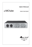
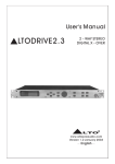
TM
LTO
DRIVE 30
User's Manual
Version 1.5
---English---
Safety Instructions
TM
LTO
All safety and operating instructions should be read before the equipment is installed and operated. We recommend that
installation be carried out by an authorised mobile electronics installation company.
Please contact your local ALTO MobileTM distributor for a list of authorised installers in your country.
To reduce the risk of electric shock and potentially damaging the equipment, do not disassemble the product. No user
serviceable parts inside; refer servicing to qualified personnel.
The equipment should be protected from moisture and rain, especially if mounted in the vehicle's trunk area or any
location that may be susceptible to water ingress.
The equipment should be situated so that its location or position does not interfere with its proper ventilation. For
example, the product should not be situated under carpeting or in a totally sealed enclosure. Trunk-mounted equipment
/amp racks should be well ventilated, using forced air cooling fans if necessary. The equipment should be situated away
from heat sources such as engine exhaust systems and radiators.
This product is designed for vehicles with a 12 VOLT NEGATIVE GROUND electrical circuit. This product must not be
used in vehicles that use a 24 Volt supply or a positive ground electrical circuit.
Great care must be taken when wiring the product to the vehicle's electrical system. Unless you are fully familiar and
trained in wiring automotive electrical systems, installation should only be undertaken by a qualified automotive electrician.
TM
LTO
Preface
Dear Customer,
Thank you for choosing the ALTO MobileTM DRIVE30 3-way digital crossover/speaker management system. We hope
you'll love the results you get from your new digital processor and enjoy using it as much as we enjoyed developing it.
The DRIVE30 is the result of considerable development work in our R&D centres in Europe and the Far East and is a
close cousin of ALTO's professional audio products. We've been designing products for musicians and recording studios
for many years - the product you now have in your hands has a fine pedigree.
The core of our digital audio products is a sophisticated DSP (Digital Signal Processor) coupled with state-of-the-art
algorithms developed by our software team over the last 7 years.
The car audio environment is worlds away from the controlled listening area of the recording studio, and yet much of the
sound processing so important to recording engineers can be applied with spectacular success to the automotive
TM
environment. ALTO Mobile is a specialist division of audio and computer software engineers, but above all we're car
audio enthusiasts. We love the challenge of trying to reproduce studio quality sound inside a moving vehicle.
We're convinced you are an important member of our team and we listen to what you say and take on board your
suggestions. It's this feedback that helps us create the products you want. Thank you.
TM
ALTO MOBILE TEAM
TM
Block Diagram
LTO
Block Diagram: DRIVE30
Input Left
Gain
Gain
5 PEQ
5 PEQ
Delay
Delay
R
O
U
T
I
N
G
Volume
5 PEQ
Band
Pass
Polarity
Compressor
Delay
Mute
Out 1
Volume
5 PEQ
Band
Pass
Polarity
Compressor
Delay
Mute
Out 2
Volume
5 PEQ
Band
Pass
Polarity
Compressor
Delay
Mute
Out 3
Volume
5 PEQ
Band
Pass
Polarity
Compressor
Delay
Mute
Out 4
Volume
5 PEQ
Band
Pass
Polarity
Compressor
Mute
Out 5
Volume
5 PEQ
Band
Pass
Polarity
Compressor
Mute
Out 6
Input Right
TM
LTO
Introduction
In purchasing the DRIVE30 you have a very powerful digital sound processor. You'll be eager to play with it - we know
what it's like when you get a new toy - but please read this manual first. If you have had your DRIVE professionally
installed and setup for you, there should be no need to touch the controls again.
DRIVE30 uses a password access system to safeguard against unauthorised parameter adjustment.
Important Warning We recommend you leave the controls exactly as set by your installer. It is extremely important that
you take great care not to send frequencies to speakers that have not been designed to handle them. In particular,
midrange speakers and tweeters must be protected from low frequencies. It would be all too easy to damage speakers
while 'playing' with the settings of the DRIVE30.
If you have not had the product installed in your vehicle yet, that's obviously the first thing you'll need to do.
We strongly recommend that you have the unit professionally installed by a specialist company authorised by the ALTO
MobileTM distributor in your country. The installation instructions in this manual are for guidance only and are not intended
to be a thorough explanation of all the steps involved in correctly fitting this unit. The instructions assume that the person
installing the equipment has been trained to carry out such work.
A computer interface and WindowsTM software is available for professional setup of the system. The same level of control
is available via the front panel buttons and LCD display but interfacing to a computer makes things easier.
The DRIVE30 is a very sophisticated digital crossover, but actually it can do far more than any conventional active crossover,
which is why we refer to it as a Speaker Management System. There are a variety of user-adjustable parameters explained
in this manual. Once you've worked on setting the sound the way you like it, you can store it in one of the 64 available
user preset memory locations. These can be quickly recalled from the panel buttons.
If this product has not been professionally installed and set-up for you, please see Band Pass Setup (Page 19) for important
details about the factory preset. In the factory default mode, you will not hear all frequencies.
TM
User Interface
LTO
4
5
1
2
3
1. Input Gain Controls: Use these controls to match the pre-amp output level from your car audio source unit.
Drive30 MAX Input level: 15 V
2. Subwoofer Gain/Frequency: These two controls adjust the level of the signal sent to the separate
SUBWOOFER OUTPUT terminal, and also adjust the Low-Pass filter point.
TM
LTO
User Interface
3. Output Gain Controls: Each frequency band has a pair of Output Gain controls. Use these controls to match the
optimum pre-amp input level of your amplifier.
Drive30 MAX Output level: 9.5 V
Input/Output Gain Setting: Proper setting of the input and output levels is important in achieving the best signal-to-noise
ratio. Use of test tones and an oscilloscope will greatly assist in setting the optimum gain levels. For this reason, system
setup is best left to a professional car audio installer.
However, if you need to get up and running without professional help, follow these steps and you won't go far wrong.
IMPORTANT: You must first correctly set the crossover points to match your system speakers BEFORE you setup the
input/output gains.
Set the ALTO's Output Gains to their 12 o'clock positions.
Turn the Input Gain controls fully counter-clockwise (minimum gain).
Turn the volume control on your CD player to about 75%.
Turn your amplifier input gains to a low setting (say 25%).
Now play some music and increase the ALTO's Input Gains until you see the arrow ( > ) symbol appear in the ALTO's
LCD level meter. Now reduce the Input Gains by an amount equal to one of the marked segments on the gain control.
Pause the music. Now set the ALTO's Output Gains to about their 3 o'clock position (i.e. 75% of maximum) and set your
amplifier input gains to their Minimum Gain position (i.e. where the amp gives its lowest output level).
Note that the maximum output level from the ALTO processor exceeds 9 volts.
Play some music and gradually increase your amplifier's gain controls until you reach your preferred maximum listening
level, or where you begin to hear any stress from the speakers. Be especially careful not to over-drive tweeters. If the
music sounds distorted with the amp gains at minimum, reduce the Output Gains on the ALTO unit.
4. Up/Down Keys: Use these to select the required Parameter Group and the specific parameter that you wish to adjust.
The group or individual parameter is shown in the LCD display. DRIVE30 uses a multi-level menu system. You move
down through the menu - from parameter group to each specific parameter you want to adjust - by using the ENTER Key.
Only after pressing ENTER are changes made.
User Interface
TM
LTO
5. Enter/ESC Keys: While searching using the UP/DOWN keys, the currently selected settings remain unchanged.
Choose a Parameter Group using the UP/DOWN keys. Now press the ENTER key. This action moves you one level lower
in the menu system. Use the UP/DOWN keys again to choose a specific parameter to adjust. Press ENTER again. Now
make your changes using the UP/DOWN keys. When you are happy with your changes, press ENTER once more. The
new settings will now be applied and should be audible.
Escape (ESC) Key: Use this key to move back up the menu system without making any changes to the current settings.
SUBWOOFER OUTPUT: DRIVE30 features six digitally processed audio channels and a separate analogue SUBWOOFER
channel. This does not mean that you cannot use the digital channels for Subwoofers. The digital audio channels can be
used for any audio frequency band between 20Hz and 20kHz, including the SUB band of 20-80Hz. The analogue output
should be considered as a kind of bonus feature, allowing this 3-way digital device to be used as a 4-way digital/analogue
device.
TM
LTO
Parameter Menus & Setup
Setting the various parameters of the DRIVE30 is achieved in one of two ways. A standard computer serial interface
allows connection to a computer and setup using a dedicated software package. Alternatively the unit can be configured
via a multi-level menu system using DRIVE30's panel buttons and the LCD display. This manual only covers setup and
adjustment using the panel buttons.
Setup Introduction
TM
Of all the ALTO Mobile sound processors, DRIVE30 (and sister model DRIVE20) is potentially the one most likely to
cause damage to your speakers if it is not setup correctly. You must take great care when setting the crossover points
for the mid and high bands. In order to safeguard settings, a password system has been incorporated to block access to
unauthorised users.
After power-up, the display will show vu-meter level data for the two input channels, the currently active preset and the
LOCK or UNLOCK condition. Pressing ENTER takes you to the main menu (i.e. takes you down one level). Pressing ESC
backtracks to the previous screen (i.e. goes up one level).
If the unit is in the UNLOCK mode, you will be able to access all menu options. If the unit is in the LOCK mode, only the
Password setup menu will be available.
Password Setup
Real
Password
New
Password
Password Setup
Real Password is a combination of 6 digits selected with the ENTER and UP/DOWN buttons (Real Password >ENTER>
Password). The currently selected digit blinks. Where the Real Password input is the same as the stored or default
password, the system will be placed in the UNLOCK condition. Otherwise it will be in the LOCK State.
Parameter Menus & Setup
TM
LTO
New Password is the function used to change the default value of Real Password in order to create a custom password.
The initial default value is 000000. The selection of the New Password follows a similar procedure as with the Real
Password (New Password >ENTER> change). To update the New Password, the system must be in the UNLOCK
Condition.
We recommend that you set a memorable custom password and write it down, but keep it at home (note: your installer
may have set a new password and over-written the factory default). To place the unit in LOCK mode, simply enter an
incorrect password (Real Password >ENTER> Password).
Load Setup
Preset 0, 1, ..., 64
Store Setup
Preset 1, ..., 64 (user)
Name editing
Muting Setup
Output 1
Off/On
Output 2
Off/On
Output 3
Off/On
Output 4
Off/On
TM
Parameter Menus & Setup
LTO
Muting Setup
Output 5
Off/On
Output 6
Off/On
Preset Load
65 presets are available, one factory preset and 64 user-definable presets. Preset 0 is the default factory preset used
as a start point when configuring the system. Attempting to load an empty user preset will produce a warning message
on the display.
Preset Store
Allows configurations to be stored as a user preset. Once a configuration has been stored, its preset location can be
renamed. The name is a combination of 8 characters of your choice selected with the ENTER and UP/DOWN buttons.
The currently selected digit blinks.
Muting Setup
Any of the six outputs can be muted (zero output). An output channel must first be selected and then the MUTE status
is selected using the UP/DOWN buttons to toggle between ON and OFF conditions.
Note: It is also possible to mute any of the outputs and store this data within individual presets by setting channel outputs
to OFF in the Routing setup menu. This can be useful for isolating faults.
TM
Parameter Menus & Setup
Routing Setup
Input L/R Setup
LTO
Output 1
Off/InL, InR, InL
R
Output 2
Off/InL, InR, InL
R
Output 3
Off/InL, InR, InL
R
Output 4
Off/InL, InR, InL
R
Output 5
Off/InL, InR, InL
R
Output 6
Off/InL, InR, InL
R
Gain
/
12dB step 0.5dB
TM
Parameter Menus & Setup
LTO
Equalizer
Setup
PEQ 1
PEQ 2
PEQ 3
Gain
/
15dB step 0.5dB
Frequency
20Hz-20KHz step 1/2oct
Band Width
0.05-3oct step 0.05oct
Gain
/
15dB step 0.5dB
Frequency
20Hz-20KHz step 1/2oct
Band Width
0.05-3oct step 0.05oct
Gain
/
15dB step 0.5dB
Frequency
20Hz-20KHz step 1/2oct
Band Width
0.05-3oct step 0.05oct
TM
Parameter Menus & Setup
LTO
Input L/R Setup
Equalizer
Setup
PEQ 4
PEQ 5
Delay
Gain
/
15dB step 0.5dB
Frequency
20Hz-20KHz step 1/2oct
Band Width
0.05-3oct step 0.05oct
Gain
/
15dB step 0.5dB
Frequency
20Hz-20KHz step 1/2oct
Band Width
0.05-3oct step 0.05oct
Delay Adj
0 - 99 ms step 1 ms
Delay Fine
0 - 978 us step 21us
TM
LTO
Parameter Menus & Setup
Routing Setup
Allows setting of the crossover channel routing configuration. For each of the 6 Output Channels you can choose to send
just the Left Input signal, the Right Input signal, a combination of both Left and Right Input signals (usually for feeding
subwoofers) or no input (OFF). The latter effectively mutes that channel. First select an output channel. Now, using the
UP/DOWN buttons to scroll through the list, choose from the routing options. To confirm your choice press ENTER. To
cancel your choice press ESC.
Input Channel Setup (INPUT L, INPUT R)
The following parameter adjustments are available for each input channel.
Input Gain
5-band parametric equalization
Delay
A multi-layer menu system is used. The various layers and the choices within the deepest layer are selected using the
UP/DOWN and ENTER keys. Use the ESC (Escape) key to cancel a selection and backtrack up through the menu layers.
Gain: Effectively acts as a master balance control.
Equalizer setup: From here you can select each of the 5 parametric filters. For each filter you can adjust Gain (cut/boost),
Frequency (the centre frequency of the filter), and Band Width (the extent to which frequencies around the centre frequency
will also be adjusted).
Delay: This allows a delay to be set on each channel. May be useful in certain circumstances. Also, setting a delay on
one side while leaving the other with no delay can produce a very interesting effect of added width and spatial depth.
This is not to be confused with 'time alignment' (see under Output Channel Setup).
TM
Parameter Menus & Setup
Output Setup
(1/2/3/4/5/6)
LTO
Volume
Equalizer
Setup
PEQ 1
PEQ 2
Gain
/
12dB step 0.5dB
/
15dB step 0.5dB
Frequency
20Hz-20KHz step 1/12oct
Band Width
0.05-3oct step 0.05oct
Gain
/
15dB step 0.5dB
Frequency
20Hz-20KHz step 1/12oct
Band Width
0.05-3oct step 0.05oct
TM
Parameter Menus & Setup
LTO
Equalizer
Setup
PEQ 3
PEQ 4
PEQ 5
Gain
/
15dB step 0.5dB
Frequency
20Hz-20KHz step 1/12oct
Band Width
0.05-3oct step 0.05oct
Gain
/
15dB step 0.5dB
Frequency
20Hz-20KHz step 1/12oct
Band Width
0.05-3oct step 0.05oct
Gain
/
15dB step 0.5dB
Frequency
20Hz-20KHz step 1/12oct
Band Width
0.05-3oct step 0.05oct
TM
Parameter Menus & Setup
LTO
Output Setup
(1/2/3/4/5/6)
Band Pass
Setup
High Pass
Frequency
Order
Low Pass
Frequency
Order
Polarity
Compressor
20Hz-20KHz step 1/12oct
Bypass, 1
2
3
4
ord
20Hz-20KHz step 1/12oct
Bypass, 1
2
3
4
ord
Direct/Invers
Threshold
29dB/0dB step 1dB
Release
0.4, 0.5, 0.7, 1.4 sec
Attack
0.05, 0.1, 0.2, 0.3 sec
TM
Parameter Menus & Setup
LTO
Delay(
)
Delay Adj
0 - 99 ms step 1 ms
Delay Fine
0 - 978 us step 21us
( )Output 5/6
no delay
Output Channel Setup (OUTPUT 1~6)
Each channel is capable of being set to operate on any band of frequencies between 20Hz and 20kHz. The following
parameter adjustments are available on each output channel.
Output Volume Level
5-band parametric equalization
Band-Pass Filter (low-pass + high-pass)
Polarity (phase)
Dynamic processor
Delay (time alignment) - Channels 1-4 only
A multi-layer menu system is used. The various layers and the choices within the deepest layer are selected using the
UP/DOWN and ENTER keys. Use ESC to cancel a selection and backtrack up through the menu layers.
Parameter Menus & Setup
TM
LTO
Volume: Acts as a master system gain control. Can be used as a safety feature to limit the maximum output available
when adjusting the panel-mounted gain controls.
Equalizer setup: From here you can select each of the 5 parametric filters. For each filter you can adjust Gain (cut/boost),
Frequency (the centre frequency of the filter), and Band Width (the extent to which frequencies around the centre frequency
will also be adjusted).
Band Pass setup: Here is where you setup the crossover point and slope for each of the output channels. Use the
UP/DOWN keys to select the Low-Pass or High-Pass filter. Now choose the Frequency or Filter Order (slope) and make
the desired settings.
Your DRIVE30 is delivered from the factory with a default setup (software version 2.0 and above). As a precaution, each
output channel has its High-Pass filter switched in at 5,000Hz. When you have finished wiring the channels corresponding
to each type of speaker, you must change the default setting of the filter in order to allow bass and lower-mid frequencies
to pass. You must then save your system setup as a new User Preset.
With the High-Pass filter, the level of frequencies BELOW the crossover point will be reduced at the rate dictated by the
slope setting. 1st Order (6dB), 2nd Order (12dB), 3rd Order (18dB) or 4t h Order (24dB) per octave.
With the Low-Pass filter, the level of frequencies ABOVE the crossover point will be reduced at the rate dictated by the
slope setting (as above).
Either filter can be switched out by setting the Filter Order (slope) to BYPASS.
Polarity 0/180
: The polarity or 'phase' of each channel can be switched Direct/Inverse.
Compressor setup: This is a form of dynamic processing used extensively in recording studios. It provides a way of
controlling the dynamic range by limiting the higher musical peaks to give a more consistent output level. In the car the
benefits include the ability to have the volume level high enough to hear softer passages above road and engine noise
without having to frantically grab the volume control on loud peaks.
Threshold sets the point below full output (0db) where the compressor/limiter begins to operate. Attack and Release
determine the time it takes for the compressor/limiter to react to changes in signal level. Generally you can leave Attack
and Release at their default settings.
TM
LTO
Parameter Menus & Setup
As the music plays, any signal peaks that exceed the level you fixed with your Threshold setting will be reduced by a
pre-set ratio. As well as providing a more consistent listening level, it also helps protect your speakers and will often
improve their overall performance.
Delay setup: Also known as 'Time Alignment'. This allows a small amount of delay to be set on each of the channels 1-4.
The amount of delay is usually calculated from physical measurements of the distances between the various speakers
and the driver's ears. The delay compensates for the difference in speaker mounting positions. When applied correctly
to all speakers in the system, the result is an improvement in the apparent stage position, height, depth and the location
and focus of the performers on the imaginary stage (usually across the dashboard).
More information is available via our web site.
Installation Instructions
TM
LTO
Mounting the Unit
DRIVE30 has two fixing 'ears' at each side, allowing it to be firmly screwed to a suitable surface. It may be mounted
vertically or horizontally. Take care not to mount the unit where it may become wet or subject to damage from items
placed in the trunk area.
Signal Inputs/Outputs
The Left and Right Channel input terminals are standard phono type sockets. Connect the low-level pre-amplifier output
cables from your car radio/cassette player, CD/receiver or other source unit to the Input terminals of DRIVE30.
This 3-way model has three sets of stereo Outputs and a single mono subwoofer output. Each of these 7 Outputs should
be connected to an amplifier input channel.
Where to place the DRIVE30 in the signal path
The DRIVE30 should be placed into the audio system circuit immediately before the amplifier(s), and after any equalizers
or sound processors that you may have.
Caution: DRIVE30 must always be placed in line BEFORE the power amplifier stage.
Power, Ground and Remote Switch-On (REM) Terminals
Caution: Before making any connections, you must stop power delivery from the battery to avoid accidental short-circuits.
The conventional way is to disconnect the Negative terminal of the battery but beware - this action will disconnect power
from all electrical items in the vehicle, including:
the audio source unit (which may require a code number to reactivate it - do you know the code?)
the security system (which may trigger and sound an alarm from its back-up battery - do you know how to override the
alarm system?)
memory modules (which may suffer memory loss if disconnected for too long).
If you have any doubts you should seek professional assistance first. Professional auto electricians will isolate individual
circuits to maintain power to the remainder of the vehicle's electrical system.
TM
LTO
Installation Instructions
At the far right of the side panel is a POWER INPUT terminal block with three screw terminals. The terminal marked
should be connected to a permanent 12 Volt supply from the vehicle battery.
12V
The terminal marked GND (Ground) should be connected to a cable which is terminated to the vehicle chassis. Ensure
that the point where this cable attaches to the vehicle chassis provides good electrical contact. If drilling a new ground
point, ensure that it is safe (check that there is nothing behind the panel you are about to drill, such as the fuel tank). It
may be necessary to rub away paintwork to expose the metal at this point - in this case, after making a firm screw
connection of the ground cable to the chassis, paint over the terminal point to protect it from the possibility of corrosion.
Where a ground point already exists (for an existing power amplifier, for example) it is generally best practice to ground
the DRIVE30 to this same point on the vehicle chassis.
The terminal marked REM accepts a 12V switched input from the source unit (Cassette or CD player). When the source
unit is switched on, a 12V pulse is sent down this line. The DRIVE30 senses this pulse and switches itself on or off. The
source unit should be equipped with a suitable Remote Switch cable - check the instruction book supplied with your audio
source unit.
If the Remote output from the source unit is already being used to switch on a power amplifier, it is usually possible to
create a 'daisy-chain' by connecting a cable from the REM or Remote terminal on the amplifier to the REM terminal of
the DRIVE30. This avoids the need to run a separate cable from the source unit.
Before reconnecting power to the circuit, double check all connections (be particularly careful to check there are no strands
of wire that could touch the chassis of the DRIVE30 or one of the other terminals).
The power-on LED next to the power input terminal block will light to show the unit is receiving power.
RS232 Computer Interface
TM
LTO
A standard RS232 computer serial interface socket allows connection of DRIVE30 to a computer capable of running
TM
Windows compatible software. A dedicated software package is available to setup DRIVE30 more easily using a
computer. DRIVE30 should be connected to a suitable computer using a 'null modem' type serial interface cable (supplied).
For information about setting up DRIVE30 via a PC, and to download the PC Editor software, visit our web site at http://www.
altomobile.com
TM
LTO
Further Information
Because of the nature of our digital sound processors and the variety of effects that can be achieved with them, there are
operational details, tips and advice too numerous to include in an instruction manual such as this. For additional information,
please visit our website at www.altomobile.com, which includes a technical discussion forum where users can exchange
ideas.
Troubleshooting
Power LED not lit: Is the Remote switch cable from the source unit (Cassette or CD Player) attached to the REM terminal
of the DRIVE30, and is the source unit switched on? Are the 12V and GND (Ground) terminals connected correctly?
Is the Ground cable properly attached to the chassis of the vehicle or to an existing ground point that is known to be OK?
No Sound: Adjust the level of the Input Gain Controls. Adjust the level of the Output Gain Controls. Are the Input and
Output signal cables correctly connected? If there is only sound from one channel, swap the Left and Right channel Input
cables at the DRIVE30 - if the fault moves to the other channel then the fault is with the cable or source unit. If the fault
remains in the same channel, isolate which speaker is not working and check back to the amplifier channels that are driving
that pair of speakers. Swap the Left and Right channel Output cables at the DRIVE30 feeding those amplifier channels.
If the fault still remains on the same speaker then the fault is with a cable or a unit after the DRIVE30 (the power amplifier
or the speaker itself). Check the amplifier gain controls and any input switching options (such as built-in crossover networks).
If the fault moves to the other speaker then the DRIVE30 may be faulty - leave it installed in your system and return to
your dealer so that they can check it.
Distorted Sound or Low Volume: Adjust the Input and Output Gain Controls of the DRIVE30, and the Input Level Controls
of the power amplifier (and input/output controls of any additional processor, if applicable).
Check if the amplifier has a built-in crossover network - is it switched correctly?
R
TM
Your ALTO Warranty
LTO
To be protected by this warranty, the buyer must be able to produce a numbered, machine printed sales receipt (original
only accepted, not a copy) from his supplying dealer that clearly shows the dealer's name and address, the buyer's name
and address, purchase date, model name/number and serial number of the product. ALTO reserves the right to verify
the authenticity of the receipt directly with the supplying dealer.
ALTO warrants the mechanical and electronic components of this product to be free of defects in material and workmanship for a period of one (1) year from the original date of purchase. If any defects occur within the specified warranty
period that are not caused by normal wear and tear or inappropriate use, ALTO shall, at its sole discretion, either repair
or replace the product.
To obtain warranty service, the product must be returned in its original shipping carton. A description of the problem will
be appreciated.
Damages/defects caused by the following conditions are not covered by this warranty:
a. Misuse, neglect or failure to operate the unit in compliance with the instructions given in the user or service manuals.
b. Connection or operation of the unit in any way that does not comply with the technical or safety regulations applicable
in the country where the product is used.
c. Damages/defects that are caused by force majeure or by any other condition beyond the control of ALTO .
Any repair carried out by unauthorised personnel will void the warranty.
This warranty is extended exclusively to the original buyer (customer of retail dealer) and is not transferable to anyone
who may subsequently purchase this product. No other person (retail dealer, etc.) shall be entitled to give any warranty
promise on behalf of ALTO .
Failure of ALTO to provide proper warranty service shall not entitle the buyer to claim (consequential) damages. In no
event shall the liability of ALTO exceed the invoiced value of the product.
This warranty does not exclude or limit the buyer's statutory rights provided by national law, in particular, any such rights
against the seller that arise from a legally effective purchase contract.
R
R
R
R
R
R
R
TM
Specifications
LTO
Channel Layout
2 inputs
Input section for each channel:
EQ Filters:
Delay line:
Output section for each channel:
Delay line:
6 outputs
1 subwoofer output
Biquadratic Bell Filters type III additive
Gain: /
15dB step 0.5dB
Frequency: 20Hz to 20KHz minimum step 1/12oct
Bandwidth: 0.05oct to 3oct step 0.05oct
0 - 99 ms step 1 ms ( fine step 21 us )
0 - 99 ms step 1 ms ( fine step 21 us )
Band Pass Filters:
Butterworth up to 4th order ( 24dB/oct )
Frequency: 20Hz to 20KHz, step 1/1 2oct
EQ Filters:
Biquadratic Bell Filters type III additive
Gain:
/ 15dB step 0.5dB
Frequency: 20Hz to 20KHz, minimum step 1/1 2oct
Bandwidth: 0.05oct to 3oct step 0.05oct
Polarity
Direct / Inverse
Limiter
Variable limiting level
Output digital volume
Mute
/
12dB step 0.5dB
ON /OFF
TM
Specifications
LTO
Analog Input section
Inputs:
Input Impedance:
Max. input Level:
2 RCA - F
400 kOhms
15 V
Analog Output section
Outputs:
Output Impedance:
Max. output level:
7 RCA - F
600 Ohms
9.5 V
Digital / Analog Interface
Amplitude Response:
Signal to Noise Ratio
THD N
Conversion
Conversion
20 Hz - 20KHz 1.5 dB
85 dB
0.02 % @ 1KHz (-3 dB)
input 20 bits Sigma - Delta
output 24 bits Sigma - Delta
Remote Control
-RS 232 for PC Connection (user interface on PC screen with MS 9X-OS)
Power Supply
Type:
Voltage supply:
Servo - controlled, Switching
11V - 16V DC (negative ground)
SEIKAKU ELECTRON INDUSTRY (H.K.) CO., LTD.
No. 1, Lane 17, Sec. 2, Han Shi W. Road, Taichung, 401 Taiwan
http://www.altomobile.com Tel: 886-4-22313737
email: [email protected] Fax: 886-4-22346757
All rights reserved to ALTO Mobile. Due to continued development in response to
customer feedback, product features and/or internal/external design may be changed
without prior notice. No photocopying, translation or reproduction of any part of this
user manual is allowed without prior written permission.Copyright c 2004 Seikaku Electron.
NF01140-1.0