1
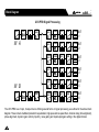
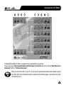
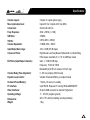
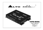
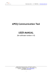
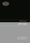
TM
LTO
UCS PRO
User's Manual
Version 1.2
---English---
TM
Introduction
LTO
Dear Customer,
Thank you for choosing the ALTO Mobile UCS PRO digital sound processor and speaker management system. We hope
you will enjoy using this product as much as we enjoy ed developing it. The ALTO Mobile range is the result of considerable
research and development in our R&D centers in Europe and the Far East. It is a very close cousin of ALTO's professional
digital signal processors. We've been designing products for musicians and recording studios for a long time, so the car
audio product you now have in your hands has an unusually fine pedigree.
TM
The passenger cabin of a vehicle is worlds away from the controlled listening environment of the recording studio, and
yet much of the same sound processing techniques can be applied with spectacular success. ALTO Mobile is a specialist
division of audio and computer software engineers, but above all we are car audio enthusiasts who love the challenge
of trying to reproduce studio quality sound inside a moving vehicle. Products such as the one you now own help to make
this possible.
TM
If you've not yet had your UCS PRO installed in your vehicle, that is obviously the first thing you will need to do. We
strongly recommend that you have the unit professionally installed and set-up by a specialist company authorized by the
ALTO Mobile distributor in your country. The installation instructions in this manual are not intended to be a thorough
explanation of all the steps involved in correctly fitting and setting up this unit. The instructions assume that the person
installing the equipment has been trained to carry out such work.
TM
You are an important member of our team. We listen to what our customers say and take on board their suggestions. It
is this feedback that helps us create the products you want. So if you have any comments, please let us know via email
to "[email protected]".
TM
THE ALTO MOBILE TEAM
E1
10R - 023484
TM
Care & Safety Instructions
LTO
All the safety and operating instructions should be read before this product is installed and operated. We
IMPORTANT recommend that installation be carried out by an authorized mobile electronics installation company. Please
TM
contact your local ALTO Mobile distributor for a list of authorized installers in your area.
DO NOT DISASSEMBLE:
No user serviceable parts inside; refer servicing to qualified personnel only.
WATER & MOISTURE:
The equipment should be protected from moisture and rain, especially if mounted in the vehicle's trunk area or any location that may be susceptible to water ingress.
PRODUCT LOCATION:
The equipment should be situated so that its location does not interfere with safe driving of the vehicle. Avoid locations
close to safety air bags. Ensure proper ventilation. The product should not be situated under carpeting or in a totally
sealed enclosure. Partly enclosed equipment racks should be well ventilated, using forced air cooling fans if necessary.
Locate away from heat sources such as engine exhaust systems and coolant radiators.
POWER SOURCE & GROUNDING:
This product is designed only for vehicles with a 12 VOLT NEGATIVE GROUND electrical circuit. This product may be
damaged if used in vehicles with a 24 Volt supply or a positive ground electrical circuit.
ELECTRICAL CONNECTION:
Improper electrical wiring may invalidate the product warranty and/or the vehicle warranty. Installation should only be
undertaken by a qualified automotive electrician, preferably MECP qualified or local equivalent.
CARE & CLEANING:
Clean only with a dry cloth. Avoid sharp objects from making contact with the casing.
SERVICING:
If a malfunction occurs, the equipment should be serviced only by qualified personnel. Return to the dealer who supplied
you with the unit.
Critical components should only be replaced with factory parts or recommended equivalents.
TM
Block Diagram
LTO
UCS PRO Signal Processing
GAIN
GATE
EQ
MASTER
DELAY
IN A
CHANNEL
DELAY
XOVER
EQ
GAIN
CMP/LIM
OUT
1
CHANNEL
DELAY
XOVER
EQ
GAIN
CMP/LIM
OUT
2
CHANNEL
DELAY
XOVER
EQ
GAIN
CMP/LIM
OUT
3
CHANNEL
DELAY
XOVER
EQ
GAIN
CMP/LIM
OUT
4
CHANNEL
DELAY
XOVER
EQ
GAIN
CMP/LIM
OUT
5
CHANNEL
DELAY
XOVER
EQ
GAIN
CMP/LIM
OUT
6
IN B
GAIN
GATE
EQ
MASTER
DELAY
The UCS PRO is a 2 input, 6 output device offering several forms of signal processing, as outlined in the above block
diagram. These include multiband parametric equalization, high-pass and low-pass filters, channel delay (time alignment),
phase alignment, dynamic gain control (cmp/lim), noise gating and input/output gain setting in the digital domain.
TM
Opening Screen (PC Editor)
LTO
1
2
3
4
5
6
7
1
8
A Windows compatible PC Editor is available for free download from our web site.
To get a copy, go to http://www.altomobile.com/html/support_forum.html and click on the link "Data Resources /
Downloads" and then "Software Downloads".
R
USEFUL
TIP
When you launch the editor on your PC, you will see the opening screen above (later software versions
may differ). Each of the numbered sections is explained in the following pages - just look for the number
icons within the text.
TM
Parameter Menus & System Set-up
LTO
There are no controls on the UCS PRO itself. The various parameters are adjusted by attaching the unit to a suitable
Personal Computer (PC) running our dedicated Windows compatible PC Editor software (available as a free download
from our website at www.altomobile.com).
R
Hook-up to the computer is achieved with the UCS PRO's 9-pin RS232 serial interface port, which is located on the same
side as the audio input/output terminals.
IMPORTANT
The large 25-pin socket on the UCS PRO is ready for the optional RM2 hardware Programmer. Do not
attempt to connect your PC to the 25-pin port - damage may result if you do.
If you have had your UCS PRO professionally installed and set-up for you, there should be no need to alter any settings.
The unit features a password access system that your installer may have set in Lock mode to safeguard the settings.
Connection to the PC (RS232, 9-pin socket)
The RS232 port allows incoming and outgoing communication between the UCS PRO and a PC. Real-time control and
set-up is possible. Set-ups made using the PC Editor can be saved as a PRESET configuration and downloaded to the
UCS PRO, where it is then stored in the unit's internal non-volatile memory. Settings stored in the UCS PRO can also be
uploaded to the PC for further editing.
1] Ensure that power to the UCS PRO and the computer is switched OFF.
2] Connect the UCS PRO to the PC's RS232 serial port using a data cable with 9-pin female plugs. The required data
cable is known as a 'null modem' (also data transfer) type serial interface cable (this is normally supplied with the UCS
PRO). Attach the other end to the 9-pin socket situated next to the audio output terminals of the UCS PRO.
3] Turn on your audio system, including the UCS PRO. Now boot-up your computer and run the PC Editor (see "First
Steps with the PC EDITOR").
USEFUL
TIP
For commands that allow set-up of the RS232 interface, look under OPTIONS in the FILE menu.
Select the RS232 tab.
TM
Parameter Menus & System Set-up
LTO
RS232 > Port: Shows the current RS232 port (COM) used by the PC Editor and allows other choices to be selected, if
available on your computer.
RS232 > BAUD RATE: Provides options to select the communication speed.
IMPORTANT Reliable data transmission can usually be expected as long as the cable length is not more than 5 meters.
ADVANCED
TIP
The RS232 serial port default speed is 9600 bits per second. In the OPTIONS menu it is possible to set
a speed of up to 115200 bits per second. If you experience transmission problems or disconnection, reduce
the speed of the serial data transmission.
First Steps with the PC EDITOR
To avoid accidentally overwriting an existing PRESET, it is important that you follow the correct routine when initiating a
session between the UCS PRO and your computer.
1] With the UCS PRO powered up and connected to your PC's serial port as described, Run the PC Editor program by
selecting the MAXI EDITOR icon in the Windows PROGRAMS menu.
R
2] The PC Editor should now load. A welcome screen will appear. This closes after 5 seconds (or click on it). Select NEW
from the FILE menu. A window will open showing several different model names, because the same software is used
for some of our pro audio models. Select UCS PRO and click OK. You will then be presented with 2 options - NEW UNIT
and NETWORK SCAN.
If your UCS PRO has already been installed and set-up and you now wish to view and/or modify some parameters,
do the following:
Select NETWORK SCAN. The program will scan your PC's serial ports. When Done, it will present a list of IDs. The ID
number of the UCS PRO is 1 (this cannot be changed). The ID list will show if the UCS PRO (ID 1) is correctly connected
or not. Pressing OK will prompt the system to retrieve (upload) all the parameters and all previously saved USER PRESETS
from the UCS PRO to your computer. A window will automatically open on your computer screen. You can now view the
settings and edit them (depending on the Lock mode).
Parameter Menus & System Set-up
TM
LTO
If your UCS PRO has not been set-up yet, or if you want to replace the existing set-up, you can create a new named
profile (NEW UNIT) within the PC Editor. Here's how:
Select NEW from the FILE menu, then UCS PRO and click OK. Select NEW UNIT. In the window that appears, type a
new name for the unit you are creating (this is optional). The Input/Output GANGING (* more information follows) options
should generally be left at their default settings (unchecked).
Press OK and a window corresponding to the unit you have just named will open up with the factory default set-up configuration and the block diagram.
Choose ONLINE from the ACTIONS menu and the PC will scan the serial port to verify that the UCS PRO is correctly
connected. The NETWORK SCAN window should show the system status (UNIT CONNECTED or NOT CONNECTED).
Pressing OK will cause all the parameters set in the PC Editor to be downloaded to the UCS PRO. An ONLINE icon will
appear to show that the UCS PRO and PC are now ready to transfer control data in real-time.
USEFUL
TIP
*Ganging: The inputs and/or each pair of outputs may be "ganged" (linked together) as stereo pairs, so
that changes are simultaneously applied to both channels. This is achieved via the MODIFY UNIT option
in the ACTIONS menu of the PC Editor. However, if you intend to use the channel delay function for speaker
'time alignment' then you should NOT gang the channels.
Every time a download is made to the UCS PRO, the user presets in the internal memory (and any unsaved
set-up you were working on) are overwritten. Selecting OFFLINE from the ACTIONS menu will cause the
IMPORTANT PC to be disconnected from the UCS PRO. Be aware that immediately selecting ONLINE again will prompt
the PC Editor to perform a new scan of the network and automatically download the settings from the PC
to the UCS PRO.
If you do not wish this to happen (i.e. if you do not wish to overwrite the current data in the UCS PRO), then you must
initiate a new session by closing the current window and then selecting NETWORK SCAN (File > New > UCS PRO >
Network Scan) so that the UCS PRO uploads to the PC.
Every time an upload is made, all the USER PRESETS stored in the UCS PRO are transferred to the corresponding
numbered presets within the PC Editor.
TM
LTO
Parameter Menus & System Set-up
Edit Mode (Password Protection)
UCS PRO incorporates a password system and your installer may have set a password to ensure that vital settings are
not altered. In this case you will NOT be able to alter all of the parameters via the PC Editor.
In the PC Editor, select FILE > OPTIONS and then the LOCK tab. This will present you with a menu:
Full Edit: This is the DEFAULT mode. No password is set at the factory. From here you can lock the unit by clicking within
the empty Partial Lock or Total Lock buttons. A text box will open, allowing you to enter a password of your own choice.
Click OK. It is important that you remember this password.
Partial Lock: In this mode, only the INPUT parameters may be edited. This is useful since it allows critical settings such
as the crossover points to be locked, while still allowing the user access to some overall EQ adjustment.
To enable Partial Lock, a new password must be entered as above. To disable the lock, click within the empty Full Edit
button. A text box will open. Type the password that was used to set lock mode. Press OK.
Total Lock: No editing is possible in this mode. To enable Total Lock, a new password must be entered as above.
To disable the lock, follow the same instructions for disabling Partial Lock.
Help File
The HELP file accessible from within the PC Editor will be updated as necessary. Since software updates after the printing
of this manual may affect the instructions provided here, please check the Help File for any later remarks.
Introduction to the PC EDITOR
Click on one of the icons on the welcome screen (the block diagram) of the PC Editor. A window will appear showing one
of several 'pages' where you can set the parameters using virtual knobs and sliders or by typing the values. Here is a
brief overview of the various functions that make up the UCS PRO PC Editor. Each is explained in more detail in the next
section.
1 GAIN CONTROL SECTION:
This page presents 8 virtual slide controls, similar to what you would see on a professional sound mixing desk. From here
you can adjust the input/output LEVELS and output channel MUTE and PHASE.
Parameter Menus & System Set-up
TM
LTO
2 NOISE GATE:
You can set the UCS PRO to cut the signal if it falls below a certain level. Most often used to cut the background noise
between music tracks.
3 PARAMETRIC EQUALIZATION (EQ):
Each of the channels (both inputs and outputs) has a fully variable 5-band parametric equalizer.
4 MASTER DELAY:
Allows a delay to be applied to the signal fed from one or both of the Input Channels.
5 CHANNEL DELAY:
Allows a delay to be applied in order to "time align" each individual output channel. Includes a graphical interface of 6
virtual speakers.
6 CROSSOVER (XOVER):
The UCS PRO is equipped with independent HIGH-PASS and LOW-PASS filters on each of the 6 output channels. For
each filter there are 10 different filter type/slope options.
7 PARAMETRIC EQUALIZATION (EQ):
Each of the channels (both inputs and outputs) has a fully variable 5-band parametric equalizer.
8 DYNAMIC GAIN CONTROL (CMP/LIM):
Each Output channel has its own independent COMPRESSOR/LIMITER. Careful setting of the parameters will help to
maintain a more consistent and pleasurable listening level and extend the performance of your speakers.
GLOBAL: Within the PC Editor's tabbed menu view, you will see a tab labelled "Global" on the far right. This window
shows the response curves of all channel outputs and provides a convenient overview of your settings.
TM
LTO
Parameter Menus & System Set-up
PRINT: Not a tabbed 'page' like those above, but an important function worth highlighting here. From the FILE menu,
selecting PRINT provides a print-out of all the parameters of the UCS PRO, together with the GLOBAL graph. View it
before printing by selecting PRINT PREVIEW.
The UCS PRO Features Explained
1 GAIN CONTROL SECTION:
The UCS PRO has no analog input or output gain controls - level adjustment is handled entirely in the digital domain.
The input stage will accept a maximum input level of 2V rms before clipping.
Click on one of the virtual level slide controls with your PC's left mouse button and hold the button down as you move
the virtual slider up or down with your cursor control. Alternatively, you can enter a dB value directly into the text box below
the slider (type a value and then press ENTER on your PC keyboard).
Clicking on a MUTE button (it will then turn red) will switch out that channel (useful during fault finding and system set-up).
Channel signal PHASE (polarity) can be set to 0 or 180 degrees. This can sometimes improve stereo imaging where
speakers are mounted substantially off-axis. It can also provide a "quick fix" if you find you have wired speakers out of
phase!
The input stage of the UCS PRO will accept an unbalanced signal that is typical of many aftermarket head
USEFUL
units (CD players etc.). Where you have a requirement to feed a high level, speaker level or Balanced type
TIP
signal from your head unit, use the optional ALTO Mobile UI-2 universal input interface.
2 NOISE GATE:
This acts rather like a water-tight valve, allowing signal to pass or not pass through it. Every audio system, especially a
complex one, produces some background noise. By setting the point (level threshold) below which the gate closes, it is
possible to minimize noise at those times when it is most likely to be audible, such as during the pauses between tracks
on a CD.
The Noise Gate cuts signal output whenever it drops below a selectable THRESHOLD. The RANGE setting dictates the
level range through which the gate will remain closed (usually this will be set to -80dB). The ATTACK and RELEASE times
Parameter Menus & System Set-up
TM
LTO
relate to the speed with which the Gate closes and opens. The default settings will usually be fine and provide gating that
works transparently, but you can use these settings to optimize the results if you hear any side-effects.
Each gate can be switched in or out of the audio circuit by clicking on the OFF/ON button. The button will turn red when
the Noise Gate is selected.
3 7 PARAMETRIC EQUALIZATION (EQ):
5-band full parametric equalization is provided on each of the Input and Output channels. The Center Frequency, Gain
and Bandwidth are all variable. In addition, the UCS PRO allows you to select from a list of different EQ contours.
Freq: The center frequency of each band can be set between approximately 16Hz and 16,000Hz.
Gain: The level at the chosen center frequency can be increased or reduced by 15dB.
Band: This dictates how the frequencies next to the center frequency will be affected during Gain boost or cut. With a
narrow bandwidth (minimum 0.05 octave), frequencies other than the center frequency and its immediate neighbours will
be largely unaltered. With a broad bandwidth (maximum 3 octaves), gain changes will be spread more widely. The effect
can be seen on the PC Editor's real-time graph.
Type: This section allows several types of EQ contour to be applied. Depending on the EQ Type selected, certain parameters (Gain, Bandwidth) are automatically set (they become greyed out).
Peaking - This default setting is the traditional parametric mode, allowing gain cut or boost at and around the chosen
center frequency.
LowSh6 - This creates a shelved response with a 6dB/octave slope, with the frequency shift occurring towards the lower
end of the frequency scale. Bandwidth adjustment is disabled in this mode.
LowSh12 - A shelved response as above but with a 12dB/octave slope.
HiSh6 - This creates a shelved response with a 6dB/octave slope, with the frequency shift occurring towards the higher
end of the frequency scale. Bandwidth adjustment is disabled in this mode.
HiSh12 - A shelved response as above but with a 12dB/octave slope.
TM
LTO
Parameter Menus & System Set-up
Notch - The Notch filter effectively removes a slice of the signal and is useful for targeting very localised problems. It
can, for example, be used as an aid to tracing spurious noises caused by vibrating panels being excited at a certain
frequency. Gain adjustment is disabled in this mode.
4 5 MASTER & CHANNEL DELAY:
A wide ranging amount of delay, from as little as 21 microseconds (that's 0.021ms, equivalent to a distance of a little over
7mm), can be set on each of the input and output channels. This allows the signal transmission from the various speaker
drive units to be aligned to the listening position (a process known as "time alignment"). Values can be input as distance
(millimetres/meters) or time (microseconds/milliseconds).
Channel (Output) Delay: A small amount of delay can be applied to the signal from each output channel. The amount of
delay is usually calculated from physical measurements of the distances between the various speakers and the driver's
ears. The delay compensates for the difference in speaker mounting positions, with the speaker furthest away (commonly
the woofer in the trunk) being the reference point to which all other speakers are aligned (i.e. delayed).
When applied correctly to all speakers in the system, the result is an improvement in the apparent stage position, height
and depth, and the location and focus of the performers on the 'virtual stage' that should extend across the dashboard.
Ideally there should also be the feeling that the low bass is coming from ahead of you, even where the woofer is physically
behind you.
Master (Input) Delay: From here you can delay an input signal before it is sent to the channel routing stage, so that all
the outputs fed by that input are delayed by the same amount. This feature is more applicable to PA applications, where
it is used to compensate for the distance between blocks of speakers in large concert halls and stadiums, but it has applications in the car too.
For example, if you are not feeding your subwoofer(s) through the UCS PRO, then you could use the Input Delays to time
align your mid-woofers (for example) to the subwoofer(s) and then use the Output Delays to time align the remaining
speaker drive units (i.e. the mids and tweeters) to the mid-woofers. This would ease the job of fine-tuning the alignment
of the subwoofer(s) to bring the bass forward, by only having to adjust the Input Delay settings.
Alternatively, you may like to try a creative use for the Input Delay. Apply a very small amount of delay on one channel
only - this can give an added sense of stereo width that, while artificial, can provide quite a striking effect.
Parameter Menus & System Set-up
TM
LTO
ADVANCED Temperature Compensation: This allows the current in-car temperature to be keyed in. The system uses
this value to compensate for any variation in the speed of sound when calculating time delay.
TIP
This is a feature carried over from the pro audio version of the software and is more applicable to PA applications, in
which it allows the delays to be set during the sound-check and quickly adjusted at the time of the concert if necessary.
The distances between speaker banks in these situations can be quite large and the difference clearly audible.
In the car the improvement will be much more subtle, but one application is in Autosound Competition. Here the demands
for the best possible imaging make even the smallest improvement worth doing. If the temperature inside the vehicle
during the contest is dramatically different from when the system was set-up, here is where you can quickly compensate
for it.
6 CROSSOVER FILTERS:
The UCS PRO is equipped with independent High-Pass and Low-Pass filters on each of the 6 output channels. For each
filter there are 10 filter type/slope options:
Butterworth type with 6dB, 12dB, 18dB or 24dB per octave slope
Bessel type with 12dB, 18dB or 24dB per octave slope
Linkwitz-Riley type with 12dB, 24dB or 48dB per octave slope
The different filter characteristics can be seen on the PC Editor's graphical display. For each of the filters, the crossover
point can be set between approximately 16Hz and 16kHz. The filter can be bypassed by selecting THRU.
Using both the High-Pass and Low-Pass filters together creates what is known as a Band-Pass filter, most often used for
optimizing the signal destined for midrange and mid-bass speakers. Also for subwoofers, by using the High-Pass as a
subsonic filter typically in the range 16-30Hz.
USEFUL
TIP
Please note that choosing the Linkwitz-Riley 48dB/octave filter will reduce the number of EQ bands available
on that channel.
TM
LTO
Parameter Menus & System Set-up
Which filter type, slope and crossover frequency you should choose will depend on the speakers you are
IMPORTANT using. Since it is important to set-up filter points carefully to maximise speaker power handling and avoid
damage, this is usually best left to a professional car audio installer.
Phase Adjustment: When using the Low-Pass filter, it is possible to adjust the phase of the signal in the low band in 5
degree steps. Combined with the 180 degrees polarity switch, it is possible to adjust the phase in the bass region through
a full 360 degrees.
When making fine adjustments to signal phase in the bass region, bear in mind that phase is related to
frequency. You cannot "phase-align" the entire low-frequency band, but you can align the phase of two
ADVANCED woofers at 50Hz, for example, or whatever frequency you choose. Where dual woofers are causing some
cancellation at a frequency "sweet spot" because of different mounting positions and/or mounting angles
TIP
and/or vent characteristics, aligning their phase can substantially improve SPL (sound pressure level) and
clarity of bass.
8 DYNAMIC GAIN CONTROL (CMP/LIM):
Each output channel has its own independent COMPRESSOR/LIMITER, allowing you to determine the amount of level
gain (i.e. increase in volume) above a threshold point that you set. This helps maintain a more consistent listening level
and both protects and extends the performance of your speakers. Input and Output levels and the amount of gain reduction are displayed on the PC screen in real-time as an aid to system set-up.
Threshold: Allows setting of the level above which the Comp/Limiter intervenes (compressing or limiting the signal). If
the music stays below this threshold setting, the level is unchanged.
Atk/Rel: There is a choice of 3 reaction speeds combining attack and release times. You can choose whether the Comp/
Limiter reacts more rapidly or slower than the default NORMAL setting when the signal exceeds or drops below the threshold. Set faster for high frequencies (tweeters), slower for bass frequencies. For midrange or full-range speakers, the
NORMAL setting will generally be the optimum one. For Subwoofers, the SLOW setting will usually be best.
Ratio: The value selected here dictates how strongly the level is controlled when it exceeds the Threshold point you set.
The range is 1.1 to 20.0, plus an additional LIMITER setting.
Parameter Menus & System Set-up
TM
LTO
The numerical values are dB values representing the amount of level increase at the input that will result in a 1dB increase
at the output of that channel. So for example, selecting a value of 6.0 will mean that for every 6dB increase at the input,
the output will rise by approximately 1dB.
LIMITER is a very hard compression setting. It prevents the channel output from increasing by more than 1dB no matter
how much the level rises at its input.
USEFUL
TIP
How we use a compressor/limiter in a car is similar to the way broadcasters use them. Like the radio station,
we get our music delivered mostly on Compact Disc, so a degree of compression will have already been
applied at the recording stage. But the recording studio sound engineer has to ensure that he doesn't make
a $10,000 audio system sound like a $500 one. He has to be careful not to compress too much. This means
that the dynamic range from the CD will often still be too much for both broadcast use and playback at high
power on a car audio system. So, like the radio stations, we tailor the sound some more by applying our
own additional processing.
There are two things we are trying to achieve when we add compression or limit the signal. Firstly we want to protect
the speakers (and to a lesser degree the power amps) from exceeding their capabilities. They will sound better (less
distortion) and live longer.
The second thing is that we want to be able to free ourselves from having to constantly tweak the volume level. Road
and engine noise has a habit of masking parts of the music, and at those times we turn it up. Then in comes that Clapton
guitar solo and we grab the volume control and spin it down before our ears begin to hurt!
What our processor allows us to do is set our preferred upper level - it's like having your own DJ poised with her hand
over the volume control, ready to turn it down when the music gets uncomfortably loud. And because we have this to
automatically control things for us at the top end, we can raise the overall volume level, which increases the level of the
softer musical passages.
ADVANCED If you would like more information on Dynamic Gain Control and compressor/limiting, including set-up
advice, please visit our website support forum where you will find a technical paper available for download.
TIP
TM
LTO
Parameter Menus & System Set-up
Working with Presets
At the lower edge of the PC Editor window is a series of commands for recalling and storing PRESETS.
To load a PRESET: Click on RECALL and then on one of the numbered red (FACTORY) or green (USER) PRESET
buttons. The selected PRESET will be loaded and its name displayed in the text box.
To save a PRESET: Click on STORE and then on one of the grey or green buttons (USER PRESETS). The grey color
means it is an empty PRESET. The green color means there is already a set-up stored at that position (which will be
overwritten if you proceed). In the window that appears, type a new PRESET NAME, then press OK. The new set-up is
now saved as a PRESET, with its name displayed in the text box. But you still need to save to a file, as follows:
Save All Settings: You must now save your UCS PRO settings (which may include several different PRESET set-ups)
as a Maxi Editor File (*.mxe) on your computer. Go To FILE, and then SAVE AS. A window will open for you to select a
destination folder for the file. You can keep the default filename or type one of your own.
When you have done this, take the UCS PRO offline (click on the icon) and then online again. This will force the PC
Editor to do a network scan. Press OK and the full system settings, including your latest PRESET, will now be downloaded
and stored in the unit's internal memory.
IMPORTANT
Remember that every time you download from your PC to the UCS PRO, the USER PRESETS in the
internal memory are replaced.
Hardware Programmer (optional item)
An optional wired Programmer (UCSPRO-RM2) is available for setting the parameters of the UCS PRO. This can be used
as an alternative (or in addition) to using a PC. A 25-pin socket is provided on the unit ready to accept the Programmer.
The RM2 Programmer can be bolted to the main body of the UCS PRO or used up to 5 meters from the main device
(i.e. at the driver's seat) during system set-up. Specific operational instructions are supplied with the Programmer itself.
Installation Instructions
TM
LTO
Mounting the UCS PRO
The UCS PRO has two fixing 'ears' at each side, allowing it to be firmly screwed to a suitable surface. Take care not to
mount the unit where it may become wet or subject to damage from items placed in the trunk area. The unit may be
mounted vertically or horizontally, but avoid mounting it upside-down (i.e. suspended under a shelf) as this may affect
heat dissipation.
IMPORTANT
The UCS PRO uses an internal cooling fan, similar to the type used in a PC, to keep its powerful DSP
device cool. The unit's side and upper vents must not be obstructed.
Where to place the UCS PRO in the signal path
The UCS PRO should be placed into the audio system circuit immediately before the amplifier(s), and after any other
equalizers or sound processors. It must always be placed in line BEFORE the power amplifier stage.
Signal Inputs/Outputs
The Input terminals are standard (unbalanced) phono type sockets, color-coded red (right channel) and white (left chann el).
Connect the low-level pre-amplifier output cables from your car radio/cassette player, CD/receiver or other source unit
to the Input terminals of the UCS PRO.
There are 6 Output channels that will generally be used as 3 sets of stereo outputs (i.e. low band, mid band and high
band), but since there are no restrictions on how each channel can be used, these are labelled simply OUT1 to OUT6.
They use standard color-coding on the terminals (red=right channel, white=left channel). Each of the output terminals
should be connected to an amplifier input channel.
USEFUL
TIP
Where you have a requirement to feed a high level, speaker level or Balanced type signal from your CD
player or other source unit to the Inputs of the UCS PRO, use the optional Alto Mobile UI-2 universal input
interface.
Power, Ground and Remote Switch-On (REM) Terminals
Caution: Before making any connections, you must stop power delivery from the battery to avoid accidental short-circuits.
The conventional way is to disconnect the Negative terminal of the battery but beware - this action will disconnect power
TM
LTO
Installation Instructions
from all electrical items in the vehicle, including:
a). The CD player or other audio source unit, which may require a code number to reactivate it. Do you know the code?
b). The security system, which may trigger an alarm from its back-up battery. Do you know how to override the alarm
system?
c). Memory modules, which may suffer memory loss if disconnected for too long.
If you have any doubts, you should seek professional assistance.
You will find a Power Input terminal block at the far end of the side panel. The green terminal block can be unplugged
from the main unit - simply grip it with your fingers on each side and pull (unplugging it can ease the wiring job if screwdriver
access to the terminal block on the panel is difficult). There are three connections to be made:
+12V
The terminal marked +12V should be connected to a permanent (i.e. not ignition switched) positive 12 Volt supply from
the vehicle battery.
GND
The terminal marked GND (Ground) should be connected to a cable which is terminated to the vehicle chassis.
Ensure that the point where this cable attaches to the vehicle chassis provides good electrical contact. It may be necessary to rub away paintwork to expose the metal at this point - in this case, after making a firm screw connection of
the ground cable to the chassis, paint over the terminal point to protect the metal from corrosion.
To avoid noise problems, ensure that this point on the vehicle chassis measures as a true ground reference. You will
need a multimeter to check that there is no (or very minimal) resistance (in ohms) between the battery negative post
and the point you have chosen on the chassis.
If drilling a new ground point, check that there is nothing behind the panel you are about to drill, such as the fuel tank!
Where a ground point already exists (for an existing power amplifier, for example) it is generally best practice to ground
the UCS PRO and any other system components to this same point on the vehicle chassis (a practice known as Star
Grounding). This helps ensure that the ground reference is the same for all components, thus avoiding the chance of
automotive noise.
Installation Instructions
TM
LTO
REM
The terminal marked REM (remote) accepts a +12V switched input from the source unit (CD player). When the source
unit is switched on, a pulse is sent down this line. The UCS PRO senses this pulse and switches itself on. Your source
unit should be equipped with a suitable Remote Switch cable - check the instruction book supplied with your Tape or CD
player.
Before reconnecting power to the circuit, double check all connections are correct and secure. On turning on the CD or
Tape player, the power-on LED next to the power input terminal block of the UCS PRO should light to show the unit is
receiving power.
USEFUL
TIP
If the Remote output from the Tape or CD player is already being used to switch on another unit that is
close to the UCS PRO, it is usually possible to 'daisy-chain' a cable from the Remote terminal on that unit
to the REM terminal of the processor. This avoids the need to run a separate cable from the player.
The unit is protected by an internally mounted fuse which only your dealer or an authorized service agent
IMPORTANT should replace if it becomes necessary. The replacement fuse must be of the same type and value as
originally fitted.
GROUND
SWITCH
UCS PRO is equipped with a Ground Switch. This alters the internal grounding arrangement within the
device. In almost all automotive applications, the switch should be in the LIFT position. In this position, the
power and signal grounds are fully isolated.
TM
LTO
Further Information
Due to the nature of our digital sound processors, there are operational tips too numerous to include in an instruction
manual such as this. For additional information, please visit our website at www.altomobile.com, which includes technical
support and customer discussion forums, together with a downloads section for software updates, technical papers etc.
Troubleshooting
Power LED not lit: Is the Remote switch cable from the source unit (Cassette or CD Player) attached to the REM terminal
of the UCS PRO, and is the source unit switched on? Are the +12V and GND (Ground) terminals connected correctly?
Is the Ground cable properly attached to the chassis of the vehicle or to an existing ground point that is known to be OK?
No Sound: With the UCS PRO connected to your PC (running the PC Editor), check that none of the output channels
are set to MUTE. Adjust the level of the Input Gains. Adjust the level of the Output Gains. Are the Input and Output signal
cables correctly connected?
If there is only sound from one channel, swap the Left and Right channel Input cables at the UCS PRO - if the fault moves
to the other channel then the fault is with the cable or the CD or Tape player. If the fault remains in the same channel,
isolate which speaker is not working and trace the circuit back to the amplifier channels that are driving that pair of speakers. Swap the Left and Right channel Output cables at the UCS PRO. If the fault still remains on the same speaker
then the fault is with a cable or a unit after the UCS PRO (the power amplifier or the speaker itself). Check the amplifier
gain controls and any input switching options (such as built-in crossover networks). If the fault moves to the other speaker
then the UCS PRO may be faulty - leave it installed in your system and return to your dealer so that they can check it.
Distorted Sound or Low Volume: Adjust the Input and Output Gains of the UCS PRO via the PC Editor or the optional RM2
Programmer. Adjust the Input Level Controls of the power amplifier (and input/output controls of any additional processor,
if applicable). Check if the amplifier has a built-in crossover network - is it switched correctly?
R
TM
Your ALTO Warranty
LTO
To be protected by this warranty, the buyer must be able to produce a numbered, machine printed sales receipt from his
supplying dealer that clearly shows the dealer's name and address, the buyer's name and address, purchase date, model
and serial number of the product.
R
ALTO warrants the mechanical and electronic components of this product to be free of defects in material and workmanship for a period of one (1) year from the original date of purchase. If any defects occur within the specified warranty
period, in accordance with the warranty regulations described below, ALTO shall, at its sole discretion, either repair
or replace the product.
If the product needs to be modified or adapted in order to comply with local technical or safety standards, such modification/adaptation shall not be considered a defect in materials or workmanship.
R
Damages/defects caused by the following conditions are not covered by this warranty:
Defects to expendable parts (typically potentiometers, switches, terminals) caused by normal wear and tear.
Misuse, neglect or failure to install or operate the unit in compliance with the instructions given in the user or service
manuals.
Electrical/mechanical connection, operation or location of the unit in any way that does not comply with the technical
or safety regulations applicable in the country where the product is used.
Damages/defects that are caused by force majeure or by any other condition beyond the control of ALTO .
Any repair carried out by unauthorized personnel will void the warranty.
R
This warranty is extended exclusively to the original buyer (customer of retail dealer) and is not transferable. In no event
shall the liability of ALTO exceed the invoiced value of the product.
R
This warranty does not exclude or limit the buyer's statutory rights provided by national law, in particular, any such rights
against the seller that arise from a legally effective purchase contract.
TM
Specifications
LTO
Channel Layout:
Max. input/output level:
Conversion:
Freq. Response:
S/N Ratio:
THD+N:
Channel Separation:
Input/Output Gain range:
Crossover Filters:
EQ Filters (Input/Output channels)
Channel Delay (Time Alignment):
Dynamic Level Control:
On-board Preset Memory:
PC Interface:
Other Interfaces:
Operating Voltage:
Dimensions:
Weight:
2 inputs / 6 outputs (phono type)
Inputs 2V rms / Outputs 2.2V rms (0dB).
24 bits A-D and D-A
20Hz - 20KHz (+/- 1dB)
>95dBA
0.05% (20Hz - 20KHz)
>100dB, 20Hz - 20KHz
-30 to +6 dB (0.5 dB steps)
High-Pass & Low-Pass (Bessel, Butterworth or Linkwitz-Riley)
Filter slopes: selectable 6, 12, 18, 24, 48dB per octave
Gain: +/- 15dB, 0.5dB step
Frequency: 15.6Hz to 16KHz
Bandwidth (Q): 0.05 to 3 octaves, 0.05 oct. step
0 - 291 ms (outputs), 0.021ms step
Variable Threshold & Ratio, per output channel
1 factory / 64 user (non-volatile)
9-pin RS232. Requires PC running Windows 98/ME/XP
25-pin D-SUB connector for optional Programmer
11 - 16V DC (negative ground)
228 x 175 x 42mm (including mounting brackets)
1.3kg
R
SEIKAKU TECHNICAL GROUP LIMITED
No. 1, Lane 17, Sec. 2, Han Shi W. Road, Taichung, 401 Taiwan
http://www.altomobile.com Tel: 886-4-22313737
email: [email protected] Fax: 886-4-22346757
All rights reserved to ALTO Mobile. Due to continued development in response to
customer feedback, product features, specifications and/or internal/external design may be
changed without prior notice. No photocopying, translation or reproduction of any part of this
user manual is allowed without prior written permission.Copyright c 2004 Seikaku Electron.
NF01194-1.0