1
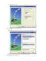
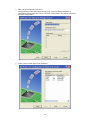
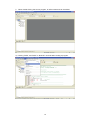
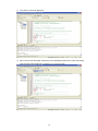
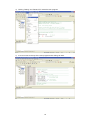
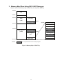
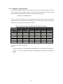
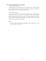
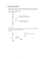
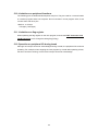
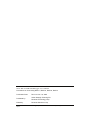
REJ10J1019-0200
M16C R8C FoUSB/UART Debugger
User’s Manual
RENESAS MICROCOMPUTER Development Environment System
M16C Family R8C/Tiny Series
Precautions on Connecting R8C/14, R8C/15, R8C/16, R8C/17
Rev.2.00
Issued : Jan. 16, 2006
Renesas Technology
www.renesas.com
Active X, Microsoft, MS-DOS, Visual Basic, Visual C++, Windows and Windows NT are either registered trademarks or
trademarks of Microsoft Corporation in the United States and other countries.
IBM and AT are registered trademarks of International Business Machines Corporation.
Intel and Pentium are registered trademarks of Intel Corporation.
Adobe and Acrobat are registered trademarks of Adobe Systems Incorporated.
All other brand and product names are trademarks, registered trademarks or service marks of their respective holders.
Keep safety first in your circuit designs!
! Renesas Technology Corporation and Renesas Solutions Corporation put the maximum effort into making
semiconductor products better and more reliable, but there is always the possibility that trouble may occur with them.
Trouble with semiconductors may lead to personal injury, fire or property damage. Remember to give due
consideration to safety when making your circuit designs, with appropriate measures such as (i) placement of
substitutive, auxiliary circuits, (ii) use of nonflammable material or (iii) prevention against any malfunction or mishap.
Notes regarding these materials
! These materials are intended as a reference to assist our customers in the selection of the Renesas Technology
product best suited to the customer's application; they do not convey any license under any intellectual property rights,
or any other rights, belonging to Renesas Technology Corporation, Renesas Solutions Corporation or a third party.
! Renesas Technology Corporation and Renesas Solutions Corporation assume no responsibility for any damage, or
infringement of any third-party's rights, originating in the use of any product data, diagrams, charts, programs,
algorithms, or circuit application examples contained in these materials.
! All information contained in these materials, including product data, diagrams, charts, programs and algorithms
represents information on products at the time of publication of these materials, and are subject to change by Renesas
Technology Corporation and Renesas Solutions Corporation without notice due to product improvements or other
reasons. It is therefore recommended that customers contact Renesas Technology Corporation, Renesas Solutions
Corporation or an authorized Renesas Technology product distributor for the latest product information before
purchasing a product listed herein. The information described here may contain technical inaccuracies or typographical
errors. Renesas Technology Corporation and Renesas Solutions Corporation assume no responsibility for any
damage, liability, or other loss rising from these inaccuracies or errors. Please also pay attention to information
published by Renesas Technology Corporation and Renesas Solutions Corporation by various means, including the
Renesas home page (http://www.renesas.com).
! When using any or all of the information contained in these materials, including product data, diagrams, charts,
programs, and algorithms, please be sure to evaluate all information as a total system before making a final decision
on the applicability of the information and products. Renesas Technology Corporation and Renesas Solutions
Corporation assume no responsibility for any damage, liability or other loss resulting from the information contained
herein.
! Renesas Technology semiconductors are not designed or manufactured for use in a device or system that is used
under circumstances in which human life is potentially at stake. Please contact Renesas Technology Corporation,
Renesas Solutions Corporation or an authorized Renesas Technology product distributor when considering the use of
a product contained herein for any specific purposes, such as apparatus or systems for transportation, vehicular,
medical, aerospace, nuclear, or undersea repeater use.
! The prior written approval of Renesas Technology Corporation and Renesas Solutions Corporation is necessary to
reprint or reproduce in whole or in part these materials.
! If these products or technologies are subject to the Japanese export control restrictions, they must be exported under a
license from the Japanese government and cannot be imported into a country other than the approved destination. Any
diversion or reexport contrary to the export control laws and regulations of Japan and/or the country of destination is
prohibited.
! Please contact Renesas Technology Corporation or Renesas Solutions Corporation for further details on these
materials or the products contained therein.
Table of Contents
1.
Connection with User System................................................................................................ 4
2.
Prepare M16C R8C FoUSB/UART debugger........................................................................ 5
3.
Memory Map When Using R8C UART Debugger ............................................................... 17
4.
Occupied Area for Monitor Program .................................................................................... 18
5.
Precautions on Using R8C UART Debugger....................................................................... 18
5.1.
When changing the communication speed and restarting the R8C UART debugger
after the R8C UART debugger ends........................................................................................ 18
5.2.
ID code of user program .............................................................................................. 18
5.3.
Area in which user program can be downloaded......................................................... 18
5.4.
Frequency characteristics ............................................................................................ 19
5.5.
Limitations on SFR operation....................................................................................... 20
5.6.
Limitations on stop mode or wait mode ....................................................................... 20
5.7.
Watchdog timer ............................................................................................................ 20
5.8.
Real-time operation of user program ........................................................................... 21
5.9.
Exceptional step execution .......................................................................................... 22
5.10.
Limitations on peripheral functions........................................................................... 23
5.11.
Limitations on flag register ....................................................................................... 23
5.12.
Operation on peripheral I/O during break................................................................. 23
1. Connection with User System
Figure 1 Connection Example with User System
Figure 2 Circuit Example with RS-232C Cable
4
2. Prepare M16C R8C FoUSB/UART debugger
In the M16C R8C FoUSB/UART debugger (R8C UART debugger), connecting a PC and the
target with the RS-232C can perform debugging.
It is not necessary to prepare a monitor program for a user since it is bundled when
installing the “M16C R8C FoUSB/UART debugger”
As for the R8C/Tiny, the monitor program is automatically programmed when starting the
R8C UART debugger. It is not necessary to program the monitor program with the M16C
FlashStarter, etc. in advance.
a) Start the High-performance Embedded Workshop. When clicking “Start”, “Program”,
“Renesas”,
“High-performance
Embedded
Workshop”
and
“High-performance
Embedded Workshop”, “Welcome!” dialog is displayed.
• [Create a new project work space]
Select when creating a new workspace.
• [Open a recent project workspace]
Select when using the existing workspace.
Display a history in an open workspace.
• [Browse to another project workspace]
Select when using the existing workspace
This button is used when the open history does not remain.
When selecting the existing workspace and pushing the [OK] button, the screen of s) is
displayed.
5
b)
Select [Create a new project workspace] radio button. Push the [OK] button.
c) The Project Generator starts. When a tool chain is installed, the following screen is open.
• [Workspace name]
Apply the workspace name newly made. “Sample” is applied as an example
• [Project name]
If the user wants to change the project name, apply the project name.
• [CPU type]
Select the applicable CPU type.
6
• [Tool chain]
When using the tool chain, select the applicable tool chain name. When the tool chain is
not used, select [None].
• [Project type]
Select a project type that wants to be used.
d) Next, set the tool chain.
Select the tool chain version and CPU series to be used, and push the [Next] button.
7
e) Next, set the RTOS.
Select the RTOS and startup file type to be used, and push the “Next” button.
f)
Next, set the heap area, etc.
Set the heap size, etc. to be used and push the [Next] button.
8
g) Next, set the stack area.
Set the stack size and push the [Next] button.
h) When the setting of the tool chain ends, the following screen is displayed.
Check the M16C R8C FoUSB/UART here and push the [Next] button.
If necessary, check other products.
9
i)
Next, set the configuration file name.
Configurations are the build option settings (e.g., output of debug information or
optimization) having their own names. The term "configuration" can also be referred to
as "build configuration".
j)
Finally, check the file name to be generated.
10
k) The above settings display the file which the High-performance Embedded Workshop
generates. When pushing the [OK] button, High-performance Embedded Workshop
starts.
11
l)
When double-clicking the source program, an editor starts and can be edited.
m) Clicking “Build”, and “Build” or “Build All” can build after creating a program.
12
n) The result of a build is displayed.
o) Next, connect with the target. Switching to the registered session file in which the setting
uses the R8C UART debugger in advance can connect simply.
13
p) The Init screen is displayed. Select [Serial] radio button and push [Reference] button.
q) Select the “R8C-Tiny Series”.
r)
Select an MCU file.
14
s) When pushing “OK”, a monitor program is downloaded.
t)
Download a user program with “Debug”, “Download” and “Download File (X30 file)”.
15
u) Clicking “Debug” and “Reset CPU” resets the user program.
v) A cursor moves to the top of the user program and a debug can start.
16
3. Memory Map When Using R8C UART Debugger
Figure 3 shows the Memory Map of R8C/Tiny On-chip Flash Memory
00000h
SFR
002FFh
00400h
RAM
User RAM
(1KB)
Monitor RAM
007FFh
006FFh
0FFDCh
undefined instruction
Overflow
BRK Instruction
0C000h
Address Match
Flash Memory
(16KB)
Monitor Program
0C800h
Single Step
User Program
Watchdog Timer
Area
Address Break
Reserved
0FFFFh
NOTES :
Vector Area
are occupied areas for the monitor program
Figure 3 Memory Map of R8C/Tiny
17
Reset
4. Occupied Area for Monitor Program
Table 1 Occupied Area for Monitor Program
ROM / RAM
Occupied Area for Monitor Program
8KB / 512B
Vector
FFE8h to FFEBh, FFECh to FFEFh,
FFF4h to FFF7h
12KB / 768B
RAM
Vector
6FFh
FFE8h to FFEBh, FFECh to FFEFh,
FFF4h to FFF7h
16KB / 1KB
RAM
6FFh to 7FFh
Flash memory C000h to C7FFh
Vector
FFE8h to FFEBh, FFECh to FFEFh,
FFF4h to FFF7h
5. Precautions on Using R8C UART Debugger
5.1. When changing the communication speed and restarting the R8C
UART debugger after the R8C UART debugger ends.
The target MCU holds the baud rate value after the R8C UART debugger ends. Therefore,
when changing the communication speed and restarting the R8C UART debugger, a
communication error occurs. (The R8C UART debugger can be started when using the
previous communication speed). When changing the communication speed, turn off the
target power and turn on the power again.
5.2. ID code of user program
Set the ID code of the user program to all FFh when using the R8C UART debugger.
Table 2 Storing Address of ID Code (R8C/10 Group)
Address
ID No.
Vector Table
0FFDFh – 0FFDCh
ID1
Undefined Instruction
0FFE3h – 0FFE0h
ID2
Overflow
0FFE7h – 0FFE4h
BRK Instruction
0FFEBh – 0FFE8h
ID3
Address Match
0FFEFh – 0FFECh
ID4
Single Step
0FFF3h – 0FFF0h
ID5
Watchdog Timer,
Oscillation Stop Detection,
Voltage Monitor 2
0FFF7h – 0FFF4h
0FFFBh – 0FFF8h
0FFFFh – 0FFFCh
ID6
ID7
(NOTES 1)
Address Break
Reserved
Reset
NOTES
1. Refer to the hardware manual for the value set in 0FFFFh.
5.3. Area in which user program can be downloaded
As shown in Figure 3, a part of RAM or Flash Memory is used for the monitor program when
using the R8C UART debugger. The R8C UART debugger does not download the user
program in the area which overlaps with a monitor program when a user program overlaps
with a monitor program. Note that the R8C UART debugger does not perform an error
output at this time.
18
5.4. Frequency characteristics
The monitor program operates in the range of the main clock (Xin) frequency which is
shown below. Use an oscillator which has this range of the frequency since the monitor
program may not operate with the frequency other than the following.
1MHz (Min.) to 20MHz (Max.)
Table 3 lists each frequency and communication available speed. However, note that
operation may not be performed when dividing the main clock and using it with 1MHz or
below even in the range of frequency shown above.
Table 3 Communication Available Speed of Each Frequency
Frequency
Communication Speed (bps)
1200
2400
4800
9600
19200
38400
20MHz
N/A
N/A
√
√
√
√
16MHz
N/A
N/A
√
√
√
√
14MHz
N/A
N/A
√
√
√
√
12MHz
N/A
N/A
√
√
√
√
10MHz
N/A
√
√
√
√
√
8MHz
N/A
√
√
√
√
√
6MHz
N/A
√
√
√
√
√
4MHz
N/A
√
√
√
√
√
2MHz
N/A
N/A
√
√
√
√
1MHz
N/A
N/A
N/A
√
√
√
√ : Communication available
N/A : Communication not available
NOTES:
A communication may not be performed depending on the conditions of temperature or
voltage. In this case, use the R8C UART debugger with the lowered communication
speed.
19
5.5. Limitations on SFR operation
Table 4 lists the limitations on a register operation. Also, the monitor program does not
operate properly when the register to which the change is disabled is changed.
Register
Table 4 Limitations on SFR Operation
Default Value Limitation
Processor Mode Register 0
Processor Mode Register 1
System Clock Control Register 0
System Clock Control Register 1
High-Speed On-Chip Oscillator Control
Register 0
High-Speed On-Chip Oscillator Control
Register 1
High-Speed On-Chip Oscillator Control
Register 2
Oscillation Stop Detection Register
Protect Register
Flag Register
Change
Reset to 00h
Reset to 00h
Reset to 08h
Reset to 28h
Reset to 03h
Single-chip mode only
---------------------Set the CM05 bit to “0”.
Set the CM13, CM15 bit to “1”.
----------------------
∗
√
∗
∗
√
----------------------
----------------------
√
----------------------
----------------------
√
Reset to 00h
-------------------------------------------
---------------------N/A
---------------------√
Writing to the D flag is ignored
∗
Do not set to “1”.
Set the value of 06FFh or below.
∗
06FFh to 07FFh are used for the monitor
program..
Do not change.
N/A
ISP
(Interrupt Stack Pointer)
Reset to 05FFh
UARTTransmit/Receive Control Register 2
32h
√ : Possible to change N/A: Disable to change ∗ : Possible to change (Limitations in part)
5.6. Limitations on stop mode or wait mode
When using stop mode or wait mode on a user program, start the R8C UART debugger in
free-run mode, and close a RAM window, C watch window and an ASM window in advance.
Also, do not operate the R8C UART debugger until the program stops at the break point by
setting the break point after exiting stop mode or wait mode.
5.7. Watchdog timer
The R8C UART debugger does not support a watchdog timer. When debugging it with the
R8C UART debugger, do not use a watchdog timer.
20
5.8. Real-time operation of user program
• Sampling Run (Sampling) Mode
In sampling mode, the execution status of the user program will be monitored regularly
when executing Go and Come. Therefore, the stop of the user program by a break can be
detected. Select this mode when performing normal debug.
• Free Run (free run) mode
In free fun mode, the execution status of the user program will not be monitored when
executing Go and Come. The stop of the user program by a break cannot be detected
although real-time operation of the user program can be kept. Therefore, even the user
program stops, the R8C UART debugger does not stop executing Go and Come. Push the
STOP button to stop the R8C UART debugger.
NOTES:
In free run mode, use the R8C UART debugger while the RAM window, C watch
window and ASM window are closed.
21
5.9. Exceptional step execution
• Software interrupt instruction
The step execution cannot be performed continuously for the instruction internal process
of the instructions (undefined instruction, overflow, BRK instruction and INT instruction)
which generate the software interrupts.
Example) INT instruction
NOP
NOP
INT
#3
NOP
JMP
Break point is skipped over
when performing step execution
MAIN
INT_3:
Address at which program
execution ought to stop
NOP
NOP
NOP
REIT
• INT instruction
Set the software break for the INT instruction internal process and use the Go command to
debug the program using the INT instruction.
Example)
NOP
INT
#3
Execute by Go command
NOP
JMP
MAIN
INT_3:
NOP
Break
NOP
REIT
22
5.10. Limitations on peripheral functions
The following pins are dedicated development tool pins. They are used for a communication
of a monitor program and a host computer. Do not use them in a user program. Also, do not
connect them with other pins.
• R8C/14-17 Groups
TxD (2pin), RxD (9pin)
5.11. Limitations on flag register
When operating the flag register on the user program, execute the FSET instruction and
FCLR instruction not to change the debug flag (D flag).
5.12. Operation on peripheral I/O during break
Although an interrupt cannot be acknowledged during a break, the peripheral I/O continues
operating. For example, when stopping the user program by a break after operating a timer,
the timer continues counting, but the timer interrupt cannot be acknowledge.
23
[Memo]
M16C R8C FoUSB/ART Debugger User’s Manual
Precautions on Connecting R8C/14, R8C/15, R8C/16, R8C/17
Publication Date
Rev.2.00 Jan. 16, 2006
Published by:
Sales Strategic Planning Div.
Renesas Technology Corp.
Edited by:
Renesas Solutions Corp.
© 2005, 2006. Renesas Technology Corp. and Renesas Solutions Corp., All rights reserved. Printed in
Japan.
M16C R8C FoUSB/UART Emulator Debugger
User’s Manual
Precautions on Connecting R8C/14, R8C/15, R8C/16, R8C/17