1
SRK-H
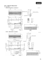
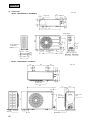
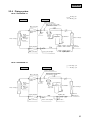
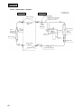
2.5.4
Refrigerant piping
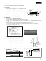
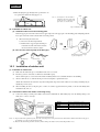
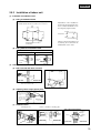
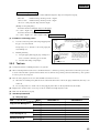
(1) Preparation
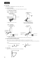
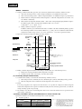
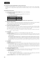
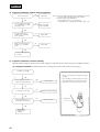
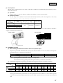
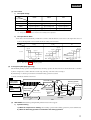
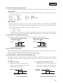
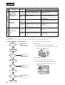
Keep the openings of the pipes covered with tapes etc. to prevent dust, sand, etc. from entering them.
Indoor unit side
Outdoor unit side
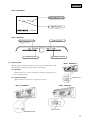
Remove
Remove
¡ Remove the flared nuts.
(on both liquid and gas sides)
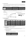
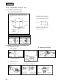
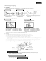
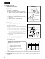
(2)
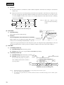
Press
Press
(Do not
turn)
Dimension A
Liquid side
(φ6.35): 9-9.5 dia
Gas side
(φ9.52): 13.2-14 dia
(φ12.7): 16.2-17 dia
¡ Remove the flared nuts.
(on both liquid and gas sides)
¡ Install the removed flared nuts to the pipes to be connected,
then flare the pipes.
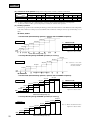
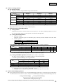
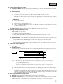
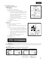
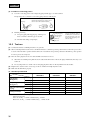
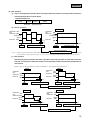
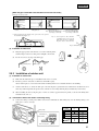
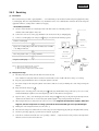
Connection of refrigerant piping
Indoor unit side
Outdoor unit side
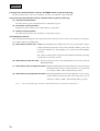
¡ Connect firmly gas and liquid side
pipings by Torque wrench.
¡ Connect firmly gas and liquid side
pipings by Torque wrench.
Spanner
(for fixing
the piping)
Torque
wrench
¡ Specified torquing value:
¡ Specified torquing value:
Liquid side (ø6.35) : 15.7~19.6 N·m(1.6~2.0 kgf·m)
Liquid side (ø6.35): 15.7~19.6 N·m(1.6~2.0 kgf·m)
Gas side (ø12.7) : 39.2~49.0 N·m(4.0~5.0 kgf·m)
Gas side (ø12.7) : 39.2~49.0 N·m(4.0~5.0 kgf·m)
¡ Use one more spanner to fix the valve.
¡ Always use a Torque wrench and back up spanner to tighten the flare nut.
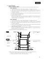
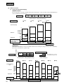
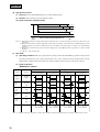
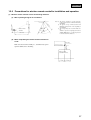
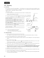
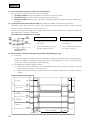
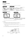
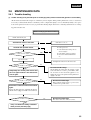
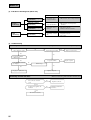
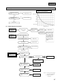
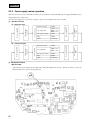
(3) Air purge
(a)
Tighten all flare nuts in the pipings both indoor and outside wall so as not to cause leak.
(b)
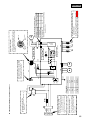
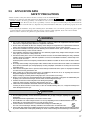
Connect operating valve, charge hose, manifold valve and vacuum pump as is illustrated below.
(c)
Open manifold valve handle Lo to its full width, and perform vacuum or evacuation.
Continue the vacuum or evacuation operation for 15 minutes or more and check to see that the vacuum gauge reads
– 0.1MPa (– 76cm Hg).
(d)
After completing vacuum operation, fully open operating valve (Both gas and liquid sides) with hexagon headed wrench.
(e)
Check for possible leakage of gas in the connection parts of both indoor and outdoor.
Compound Pressure
(Gauge)
gauge
–76 cm Hg
Handle Lo
(pressure)
Stop valve
(Three-way
valve)
Stop valve
(Two-way valve)
Charge hose
Service port
82
Manifold
valve
Handle Hi
(pressure)
Charge hose
Vacuum pump