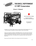
1
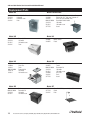
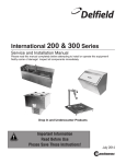
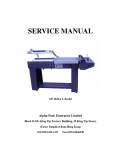
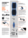
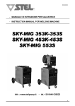
Delfield
™
®
200 & 300 SERIES
Service and Installation Manual
Please read this manual completely before attempting to install or operate this equipment!
Notify carrier of damage! Inspect all components immediately.
Drop In and Undercounter Products
CAUTION
Important Information
Read Before Use
Please Save These Instructions!
February 2013
200 and 300 Series Service and Installation Manual
Important Warning And Safety Information
WARNING
Read This Manual Thoroughly Before Operating, Installing, Or Performing Maintenance On The Equipment.
WARNING
Failure To Follow Instructions In This Manual Can Cause Property Damage, Injury Or Death.
WARNING
Do Not Store Or Use Gasoline Or Other Flammable Vapors Or Liquids In The Vicinity Of This Or Any Other
Appliance.
WARNING
Unless All Cover And Access Panels Are In Place And Properly Secured, Do Not Operate This Equipment.
WARNING
This Appliance Is Not Intended For Use By Persons Who Lack Experience Or Knowledge, Unless They Have
Been Given Supervision Or Instruction Concerning Use Of The Appliance By A Person Responsible For Their
Safety.
WARNING
This Appliance Is Not To Be Played With.
Warning
Do Not Clean With Water Jet.
WARNING
Do Not Use Electrical Appliances Inside The Food Storage Compartment Of This Appliance.
CAUTION
Observe the following:
•
Minimum clearances must be maintained from all walls and combustible materials.
•
Keep the equipment area free and clear of combustible material.
•
Allow adequate clearance for air openings.
•
Operate equipment only on the type of electricity indicated on the specification plate.
•
Unplug the unit before making any repairs.
•
Retain this manual for future reference.
Delfield
™
2
For customer service, call (800) 733-8829, (800) 733-8821, Fax (989) 773-3210, www.delfield.com
®
200 and 300 Series Service and Installation Manual
Contents
Receiving And Inspecting Equipment......................................... 3
Serial Number Information......................................................... 4
Warramtu Information................................................................ 4
Regulatory Certifications............................................................. 4
Specifications.............................................................................. 5
Installation................................................................................6-7
Operation..................................................................................... 8
Maintenance................................................................................ 8
Wiring Diagram........................................................................... 9
Replacement Parts.................................................................9-10
Standard Labor Guidelines.......................................................11
Receiving And Inspecting The Equipment
Even though most equipment is shipped packaged, care
should be taken during unloading so the equipment is not
damaged while being moved into the building.
1. Visually inspect the exterior of the package and skid or
container. Any damage should be noted and reported to
the delivering carrier immediately.
2. If damaged, open and inspect the contents with the
carrier.
3. In the event that the exterior is not damaged, yet upon
opening, there is concealed damage to the equipment
Delfield
™
4.
5.
6.
7.
notify the carrier. Notification should be made verbally as
well as in written form.
Request an inspection by the shipping company of the
damaged equipment. This should be done within 10 days
from receipt of the equipment.
Visually inspect the refrigeration package. Be sure lines
are secure and base is still intact.
Freight carriers can supply the necessary damage forms
upon request.
Retain all crating material until an inspection has been
made or waived.
®
For customer service, call (800) 733-8829, (800) 733-8821, Fax (989) 773-3210, www.delfield.com
3
200 and 300 Series Service and Installation Manual
Serial Number Information
Models
Serial Tag Location
N225, N227
On the compressor stand next to the temperature control
203, 204, 204P, 248, 250, 305 On the bottom of the ice chests
240
On the back
242
On the bottom of the sink
307
Underneath the top
Always have the serial number of your unit available when calling
for parts or service.
©2013 The Delfield Company. All rights reserved. Reproduction without
written permission is prohibited. “Delfield” is a registered trademarks of The
Delfield Company.
Warranty Information
Visit http://www.delfield.com/minisite/service/warranty_info to:
• Register your product for warranty.
• Verify warranty information.
• View and download a copy of your warranty.
Regulatory Certifications
All Models are certified by:
National Sanitation Foundation (NSF)
Electical models are also certified by:
Underwriters Laboratories (UL)
Underwriters Laboratories of Canada (ULC)
Delfield
™
4
For customer service, call (800) 733-8829, (800) 733-8821, Fax (989) 773-3210, www.delfield.com
®
200 and 300 Series Service and Installation Manual
Specifications
MODEL
L
D
H
SHIP
CUTOUT SIZE
WEIGHT
N225
16.56”
(42.1cm)
27.87”
26.75”
115lbs
(70.8cm) (67.9cm) (52kg)
N227
30”
(76.2cm)
27.87”
26.75”
191lbs
(70.8cm) (67.9cm) (87kg)
CABINET H.P.
CAPACITY
AMP
VOLT
NEMA
PLUG
DESIGN
LOAD BTU
SYSTEM
CAP. BTU
EVAP BTU/
TD/TEMP
25.75” x 14.62”
(65.4cm x 37.1cm)
6 gal.
1/5
5.3
115
5-15P
292
411
20/20°/-23°
25.75” x 28.00”
(65.4cm x 71.1cm)
12 gal.
1/5
5.3
115
5-15P
473
532
28/19°/-22
DROP-IN FREEZERS
DROP-IN FREEZERS WITH LEXAN® LID
N225L
16.56”
(42.1cm)
27.87”
26.75”
115lbs
(70.8cm) (67.9cm) (52kg)
25.75” x 14.62”
(65.4cm x 37.1cm)
6 gal.
1/5
5.3
115
5-15P
292
411
20/20°/-23°
N227L
30”
(76.2cm)
27.87”
26.75”
191lbs
(70.8cm) (67.9cm) (87kg)
25.75” x 28.00”
(65.4cm x 71.1cm)
12 gal.
1/5
5.3
115
5-15P
473
532
28/19°/-22
DROP-IN WATER STATIONS AND ICE STORAGE
203
ice chest
20.25”
(51.4cm)
20.25”
23.25”
52lbs
(51.4cm) (59.1cm) (24kg)
19.25” x 19.25”
(48.9cm x 48.9cm)
90lbs
(41kg)
N/A
N/A
N/A
N/A
N/A
N/A
N/A
204
water and ice
station
24”
(61.0cm)
21”
23.5”
47.5lbs
(53.3cm) (59.1cm) (22kg)
21” x 17.75”
(53.3cm x 45.1cm)
45lbs
(20kg)
N/A
N/A
N/A
N/A
N/A
N/A
N/A
204P
water and ice
station
24”
(61.0cm)
21”
27”
47.5lbs
(53.3cm) (68.6cm) (22kg)
21” x 17.75”
(53.3cm x 45.1cm)
45lbs
(20kg)
N/A
N/A
N/A
N/A
N/A
N/A
N/A
240
ice chest with
cover
21”
(53.3cm)
17.5”
17”
36lbs
(44.5cm) (43.2cm) (16kg)
—
75lbs
(34kg)
N/A
N/A
N/A
N/A
N/A
N/A
N/A
248
water and ice
station
31”
(78.7cm)
15”
22.5”
28lbs
(38.1cm) (57.2cm) (13kg)
28” x 12.5”
(71.1cm x 31.8cm)
45lbs
(20kg)
N/A
N/A
N/A
N/A
N/A
N/A
N/A
305
ice chest with
cover
21.25”
(54.0cm)
15.25”
13”
18lbs
(38.7cm) (33.0cm) (8kg)
12.5” x 17.75”
(31.8cm x 45.1cm)
45lbs
(20kg)
N/A
N/A
N/A
N/A
N/A
N/A
N/A
307
glass filler
12”
(30.5cm)
12”
9.5”
7lbs
(30.5cm) (24.1cm) (3kg)
9.00” x 9.00”
(23cm x 23cm)
—
N/A
N/A
N/A
N/A
N/A
N/A
N/A
17” x 12.5”
(43.2cm x 31.8cm)
—
N/A
N/A
N/A
N/A
N/A
N/A
N/A
N/A
N/A
N/A
N/A
N/A
N/A
N/A
UNDERCOUNTER SINKS, WATER STATIONS AND ICE STORAGE
242
UC sink & faucet
18”
(45.7cm)
250
UC sink, ice chest 46”
14.06”
and water station (116.8cm) (36cm)
Delfield
™
13.5”
12.75”
20lbs
(34.3cm) (32.4cm) (9kg)
22.75”
81lbs
(57.8cm) (37kg)
45” x 13”
45lbs
(114.3cm x 33.0cm) (20kg)
®
For customer service, call (800) 733-8829, (800) 733-8821, Fax (989) 773-3210, www.delfield.com
5
200 and 300 Series Service and Installation Manual
Installation - Models N225, N225L, N227 And N227L
Location
Units in this manual are intended for indoor use only.
The refrigeration system has been factory tested and
should require no further adjustment during installation.
For the most efficient refrigeration, be sure to provide
good air circulation inside and outside the unit.
Outside Cabinet: Be sure that the unit has access to
ample air. Avoid hot corners and locations near stoves
and ovens.
Counter Cutouts
For installation provide a cutout in the counter as shown
(see illustration 1 or 2). The counter must be sturdy
enough to hold the combined weight up to 300 pounds
of the drop-in and the product stored inside.
25.75"
65.4cm
N225 N225L N227
or N227L DROP-IN
TO
UT
1.00"/2.5cm (min.)
CU
.75"/1.9cm
radius
The louver provided must be installed
in front of the condensing unit’s finned
coil (see illustration 3). A second cutout
must be made at the rear or end of
the equipment to allow air flow through
the unit. No louver is provided for the
second cutout. Any restriction to the
proper air flow, total or partial, will void
the compressor warranty.
14.62"
37.1cm
1.00"/2.5cm (min.)
COUNTERTOP
Illustration 1. Model N225 & N225L cutout dimensions
25.75"
65.4cm
LOUVER
13.00" x 25.00"
33.0cm x 63.5cm
1.00"/2.5cm (mi
TYPICAL
COUNTER
CABINET
LOUVER CUTOUT SIZE
12.00" x 23.50"
30.5cm x 59.7cm
(typical installation)
NOTE: A second cutout
(without louver) must
also be made to allow
proper air flow.
Illustration 3. N225 N225L N227 & N227L louver installation
CU
TO
UT
Electrical Connection
28.0"
71.1cm
.75"/1.9cm radius
COUNTERTOP
1.00"/2.5cm (mi
Illustration 2. Model N227 & N227L cutout dimensions
Refer to the amperage data, the serial tag, your local
code or the National Electrical Code to be sure the unit
is connected to the proper power source. A protected
circuit of the correct voltage and amperage must be run
for connection of the line cord.
If the unit does not operate after it is plugged in, check
the thermostat to see if it was inadvertently turned OFF
during installation.
The unit must be disconnected from
the power source whenever performing
service or maintenance functions.
Delfield
™
6
For customer service, call (800) 733-8829, (800) 733-8821, Fax (989) 773-3210, www.delfield.com
®
200 and 300 Series Service and Installation Manual
Installation - Models 203, 204, 204P, 240, 242, 248, 250, 305 And 307
Location
Drain
Units in this manual are intended for indoor use only.
Provided 1” (2.5cm) drain, nut and washer must be
field installed to an appropriate container or floor drain
following local code requirements. Sinks come standard
with 1-1/2” basket strainer assemblies.
Avoid hot corners and locations near stoves and ovens.
Counter Cutouts
For installation, provide a cutout in the counter sized
according to the chart below. The counter must be
sturdy enough to hold the combined weight up to 300
pounds of the drop-in and the product stored inside.
Model
Cutout Size
Mounting
Studs
1/2” IPS
Water
Hookup
Drain
203
ice chest
19.25” x 19.25”
(48.9cm x 48.9cm)
N/A
N/A
(1) 1”
204
water and ice
station
21” x 17.75”
(53.3cm x 45.1cm)
4
1
(2) 1”
204P
water and ice
station
21” x 17.75”
(53.3cm x 45.1cm)
4
1
(2) 1”
240
ice chest with cover N/A
N/A
N/A
(1) 1”
242
UC sink & faucet
17” x 12.5”
(43.2cm x 31.8cm)
N/A
2
(1) 1-1/2”
248
water and ice
station
28” x 12.5”
(71.1cm x 31.8cm)
4
1
(2) 1”
250
UC sink, ice chest
and water station
45” x 13”
N/A
(114.3cm x 33.0cm)
3
(2) 1”
(1) 1-1/2”
305
ice chest with cover 12.5” x 17.75”
(31.8cm x 45.1cm)
4
N/A
(1) 1”
307
glass filler
4
1
(1) 1”
9.00” x 9.00”
(23cm x 23cm)
Water Connection
All 1/2” (1.3cm) IPS water inlets must be field connected
following local code requirements.
Mounting Studs
13.50” (34.3cm)
19.25” (48.9cm)
204/204P Stud Location
Equipment with mounting studs are pictured below.
Mark the stud locations according to the measurements
or place the equipment in the cutout to mark the stud
locations. Drill 0.37” (1.0cm) diameter holes through the
counter for the studs.
29.50” (74.9cm)
248 Stud Location
10.12” (25.7cm)
307 Stud Location
19.375” (49.2cm)
305 Stud Location
22.00” (55.9cm)
204/204P Stud Location
10.12” (25.7cm)
307 Stud Location
13.25” (33.7cm)
305 Stud Location
Delfield
™
®
For customer service, call (800) 733-8829, (800) 733-8821, Fax (989) 773-3210, www.delfield.com
7
200 and 300 Series Service and Installation Manual
Operation - Models N225, N225L, N227 And N227L
After installation, the unit will begin operating simply
by plugging it into the proper outlet. If the unit does
not operate after being plugged in, check to see if the
thermostat is in the OFF position.
The models 225 and 227 are designed to hold
frozen products at a temperature range of 5°F to
-5°F (-15°C to -21°C). The thermostat is located in
the machine compartment.
Maintenance - Models N225, N225L, N227 And N227L
In order to maintain proper refrigeration performance,
the condenser fins must be cleaned of dust, dirt and
grease every three months. If conditions are such that
the condenser is totally blocked in three months, the
frequency of cleaning should be increased.
The lid should be cleaned regularly with a soft
cloth or sponge and solution of soap and water to
maintain it’s ability to seal properly.
Clean the condenser with a vacuum cleaner or stiff
brush. If extremely dirty, a commercially available
condenser cleaner may be required.
Defrosting must be done manually after 3/8” of ice
accumulation. To defrost disconnect power to the
equipment or turn the thermostat knob to the OFF
position.
Maintenance - Models 203, 204, 204P, 240, 242, 248, 250, 305 And 307
The interior and exterior of these models may be cleaned
using soap and warm water. If this is not sufficient, try
ammonia and water or a non-abrasive cleaner. Be sure
to rinse thoroughly with clean water after using ammonia
or a cleaner. When cleaning the exterior, always rub
with the “grain” of the stainless steel to avoid marring
the finish.
Do not use an abrasive cleaner. Abrasive
cleaners will scratch the stainless steel
and plastic.
Delfield
™
8
For customer service, call (800) 733-8829, (800) 733-8821, Fax (989) 773-3210, www.delfield.com
®
200 and 300 Series Service and Installation Manual
Wiring Diagram - Models N225, N225L, N227 And N227L
WH ITE
CONDENSER
FAN
GREEN
POWE R
SUPPLY
115V/60 Hz/1
Ø
BLACK
CONTROL
COM PRESSOR
GND
Replacement Parts - Models N225, N225L, N227 And N227L
4
3
5
6
2
1
10
7
9
8
12
11
Key
Part No.
Description
Key
Part No.
Description
1
3234188
Cover (solid)
9
2162691
Fan motor
3234189
Cover (see-through)
10
3516172
Fan blade
2
1701273
Trim gasket
11
026-ANM-0030
Fan baffle
3
2183349
Harness, power cord
12
3516067
Condensing coil
4
3526996
227 Compressor, 1/5 H.P. (404A)
-
3516287
High pressure switch
3526997
225 Compressor, 1/5 H.P. (404A)
-
3516191
Filter dryer
5
3977986
Wire fan guard
-
2194787
Start capacitor
6
3516047
Temperature control
-
3516446
Compressor relay
7
024-ADB-0040
Compressor stand
-
359-411-0003
Louvered panel (cutout 12” x 23.5”
8
031-264-0000
Fan motor bracket
-
Purchase locally
Capillary tube, .031” i.d. 120”
Delfield
™
®
For customer service, call (800) 733-8829, (800) 733-8821, Fax (989) 773-3210, www.delfield.com
9
200 and 300 Series Service and Installation Manual
Replacement Parts
Model 203
Models 204 And 204P
000-AUO-0030 Removable lid with handle
3234110 Lid handle
9321011
Lid handle screw
3234242Drain
Model 242
Model 240
000-AUO-0001
3234110
9321011
3234242 Removable lid
Lid handle
Lid handle screws
Drain
Model 248
3234007
3234076 Basket Strainer
Faucet
Model 250
3977953Guard
3234088 Glass filler
3234242 Drain
000-AUO-0030
Removable lid
3234110 Lid handle
9321011
Lid handle screw
Model 305
3234242 000-AUO-0030
3234110 9321011
3234088 Glass filler 9.5” high, max. ht glass 8”
3234303
Pitcher filler 13.5” high, max. ht pitcher 12”
3234242
Drain (ice chest and water filler)
000-AUO-0030
Removable lid with handle
3234110 Lid handle
9321011
Lid handle screw
3977953Guard
3234007 Basket strainer
3234076 Faucet
000-AUO-0030
Removable lid
3234110 Lid handle
9321011
Lid handle screw
3234088 Glass filler
3234242 Drain
3977953Guard
Model 307
Drain
Removable lid
Lid handle
Lid handle screw
3234088 Glass filler 9.5” high, max. ht glass 8”
3977953Guard
3234242Drain
Delfield
™
10
For customer service, call (800) 733-8829, (800) 733-8821, Fax (989) 773-3210, www.delfield.com
®
200 and 300 Series Service and Installation Manual
Standard Labor Guidelines To Repair Or Replace Parts On Delfield Equipment
Advice and recommendations given by Delfield Service Technicians do not constitute or guarantee any special coverage.
•A maximum of 1-hour is allowed to diagnose a defective component.
•A maximum of 1-hour is allowed for retrieval of parts not in stock.
•A maximum travel distance of 100 miles round trip and 2-hours will be reimbursed.
•Overtime, installation/start-up, normal control adjustments, general maintenance, glass breakage, freight damage, and/or
correcting and end-user installation error will not be reimbursed under warranty unless pre-approved with a Service Work
Authorization from Delfield. You must submit the number with the service claim.
Labor Of 1-Hour Is Allowed To Replace:
•Compressor Start Components and Overload Protector
•Thermostat
• Condenser Fan Motor and Blade
Labor Of 2 Hours To Replace:
•Locate/Repair Leak
• High Pressure Switch
Labor Of 3 Hours To Replace:
•Condenser Coil
• Capillary Tubing
Labor Of 4 Hours To Replace:
•Compressor
This includes recovery of refrigerant and leak check.
$55.00 maximum reimbursement for refrigerant recovery (includes recovery machine, pump, torch, oil, flux, minor fittings,
solder, brazing rod, nitrogen, or similar fees.)
Refrigerants:
•R404A A maximum of $15.00/lb. or $1.00/oz. will be reimbursed.
Delfield
™
®
For customer service, call (800) 733-8829, (800) 733-8821, Fax (989) 773-3210, www.delfield.com
11
Delfield
™
®
Covington, TN
Mt. Pleasant, MI
Thank you for choosing Delfield!
Help is a phone call away. Help our team of professional, courteous customer
service reps by having your model number and serial number available at the time
of your call (800) 733-8829.
Model:________________________ S/N: _______________________
Installation Date:________________
For a list of Delfield’s authorized parts depots,
visit our website at www.delfield.com
Register your Delfield warranty
online. Go to www.delfield.com
under the service tab to complete.
Delfield
™
®
980 S. Isabella Rd., Mt. Pleasant, MI 48858, U.S.A. • (989) 773-7981 or (800) 733-8829 • Fax (989) 773-3210 • www.delfield.com
Delfield reserves the right to make changes in design or specifications without prior notice. ©2013 The Delfield Company. All rights reserved. Printed in the U.S.A.
DM200_300 02/13
9291456