1
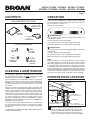
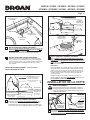
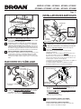
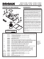
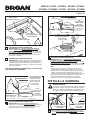
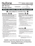
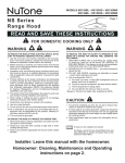
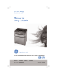
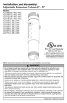
MODELS QP130BL • QP130BLC • QP130SS • QP130SSC
QP130WW • QP130WWC • QP136BL • QP136SS • QP136WW
EVOLUTION 1
QP130, QP136 Series Range Hoods
TM
Page 1
READ AND SAVE THESE INSTRUCTIONS
FOR DOMESTIC COOKING ONLY
WARNING
WARNING
TO REDUCE THE RISK OF FIRE, ELECTRIC SHOCK, OR INJURY TO PERSONS, OBSERVE THE FOLLOWING:
1. Use this unit only in the manner intended by the manufacturer.Ifyouhavequestions,contactthemanufactureratthe
addressortelephonenumberlistedinthewarranty.
2. Beforeservicingorcleaningunit,switchpoweroffatservice
panelandlocktheservicedisconnectingmeanstoprevent
power from being switched on accidentally. When the servicedisconnectingmeanscannotbelocked,securelyfasten
a prominent warning device, such as a tag, to the service
panel.
3. Installationworkandelectricalwiring(includingswitchlocation) must be done by a qualified person(s) in accordance
withallapplicablecodesandstandards,includingfire-rated
construction.
4. Providesufficientairforpropercombustionandexhaustingof
gasesthroughtheflue(chimney)offuelburningequipment
to prevent backdrafting. Follow the combustion equipment
standardssuchasthosepublishedbytheNationalFireProtectionAssociation(NFPA),theAmericanSocietyforHeating,RefrigerationandAirConditioningEngineers(ASHRAE),
andlocalcodes.
5. Thisproductmayhavesharpedges.Becarefultoavoidcuts
andabrasionsduringinstallationandcleaning.
6. When cutting or drilling into wall or ceiling, do not damage
electricalwiringandotherhiddenutilities.
7. Ductedfansmustalwaysbeventedtotheoutdoors.
8. Useonlymetalductwork.
9. Donotusethisfanwithanysolid-statespeedcontroldevice.
10.Asanalternative,thisproductmaybeinstalledwiththeULapproved cord kit designated for the product, following instructionspackedwiththecordkit.
11.Thisunitmustbegrounded.
TO REDUCE THE RISK OF INJURY TO PERSONS IN THE
EVENT OF A RANGE TOP GREASE FIRE, OBSERVE THE
FOLLOWING:*
1. SMOTHER FLAMES with a close-fitting lid, cookie sheet,
or metal tray, then turn off the burner. BE CAREFUL TO
PREVENTBURNS.Iftheflamesdonotgooutimmediately,
EVACUATEANDCALLTHEFIREDEPARTMENT.
2. NEVERPICKUPAFLAMINGPAN—Youmaybeburnedor
spreadthefire.
3. DONOTUSEWATER,includingwetdishclothsortowels-
violentsteamexplosionwillresult.
4. UseanextinguisherONLYif:
A. You know you have a ClassABC extinguisher and you
alreadyknowhowtooperateit.
B. Thefireissmallandcontainedintheareawhereitstarted.
C. Thefiredepartmentisbeingcalled.
D. Youcanfightthefirewithyourbacktoanexit.
*Basedon“KitchenFireSafetyTips”publishedbyNFPA.
TO REDUCE THE RISK OF A RANGE TOP GREASE FIRE:
1. Never leave surface units unattended at high settings.
Boiloverscausesmokingandgreasyspilloversthatmayignite.Heatoilsslowlyonlowormediumsettings.
2. Always turn hood ON when cooking at high heat or when
cookingflamingfoods(i.e.CrepesSuzette,CherriesJubilee,
PeppercornBeefFlambé).
3. Clean ventilating fans frequently. Grease should not be allowedtoaccumulateonfanorfilter.
4. Use proper pan size.Always use cookware appropriate for
thesizeofthesurfaceelement.
Installer: Leave this manual with the homeowner.
Homeowner: Cleaning, Maintenance and Operating
instructions on page 2.
CAUTION
1. Forindooruseonly.
2. Forgeneralventilatinguseonly.Donotusetoexhausthazardousorexplosivematerialsandvapors.
3. To avoid motor bearing damage and noisy and/or unbalanced impeller, keep drywall spray, construction dust, etc.,
offpowerunit.
4. Do not use over cooking equipment greater than 60,000
BTU/hr.astheblowermotorwillshutdownintermittantly.
5. Yourhoodmotorhasathermaloverloadwhichwillautomaticallyshutoffthemotorifitbecomesoverheated.Themotor
willrestartwhenitcoolsdown.Ifthemotorcontinuestoshut
offandrestart,havethehoodserviced.
6. ThetopofthehoodMUSTNOTBELESSthan24”andata
maximumof30”abovecooktopforbestcaptureofcooking
impurities.
7. Thishoodisnotintendedtobeusedasashelf.
8. Please read specification label on product for further informationandrequirements.
NOTE Ifhoodistobeinstallednon-ducted:
Purchaseasetof(2)non-ductedfiltersfromyour
localdistributororretailerandattachthemtothe
aluminummeshfilters.
Register your product online at: www.broan.com/register
MODELS QP130BL • QP130BLC • QP130SS • QP130SSC
QP130WW • QP130WWC • QP136BL • QP136SS • QP136WW
Page 2
CONTENTS
OPERATION
INCLUDED WITH THE HOOD:
(1) 3¼” X 10”
DAMPER / DUCT
CONNECTOR
(2)
GREASE
FILTERS
(1) 7” ROUND
DUCT
CONNECTOR
(1) PARTS BAG CONTAINING:
(3)
WIRE
NUTS
(9)
#8 X 1/4”
DUCT
CONNECTOR
SCREWS
(1)
BULB
SUCTION
CUP TOOL
(5)
#10 X 5/8”
RD. HD.
MOUNTING
SCREWS
CLEANING & MAINTENANCE
Forperformance,appearance,andhealthreasons,cleanfilter,
fanandgrease-ladensurfaces.Useonlyacleanclothandmild
detergentsolutiononstainlessandpaintedsurfaces.
AlwaysturnthehoodONbeforecookinginordertoestablishan
airflowinthekitchen.Afterturningofftherange,letthehoodrun
forafewminutestocleartheair.
Operatethehoodasfollows:
0
0
1
2
LIGHT SWITCH
This3-positionrockerswitchturnslightsONandOFFandcontrols
theirintensity.
Leftrockerposition(0)turnslightsOFF.
Centerrockerposition(1)turnslightsONtolowintensity.
Rightrockerposition(2)turnslightsONtohighintensity.
NOTE:
This hood utilizes an offset blower design to achieve greater
performanceandlowersoundlevels.Asaresult,youmaynotice
thatcookingimpuritiesaremoreattractedtoonesideorappear
tobepulled-infasterthantheyappearontheoppositeside.This
iscompletelynormal.Thehoodhasbeendesignedandtestedto
provide good capture of cooking impurities and odors under all
normalcookingconditionsregardlessofthecookinglocationonthe
cooktop.Pleasenotethatcookingontherearburnerswillalways
resultinthebestcaptureresults,regardlessofthehooddesign.
PREPARE HOOD LOCATION
ROOF CAP
Clean the non-duct recirculating filter surfaces frequently with
adampclothandamilddetergent.DONOTimmersefiltersin
waterorputindishwasher.Thespecial“CleanSense”feature
indicateswhenthefilteristobereplaced.Theblueandyellow
stripswillblendtogreenwhenitistimetochangethefilter.The
“CleanSense”featureworksbestwhenfacingtowardthecooking surface. Change the non-duct recirculating filters every 6
months.Forreplacementnon-ductrecirculatingfilters-purchase
S99010353orModelBPPF30for30”hoods,orS99010354or
ModelBPPF36for36”hoods.
Use120V,35W,shieldedhalogenbulbs-MR16withGU10base.
Purchasebulbsseparately.
2
BLOWER SWITCH
This 3-position rocker switch turns blower ON and OFF and
controlsblowerspeed.
Leftrockerposition(0)turnsblowerOFF.
Centerrockerposition(1)turnsblowerONtolowspeed.
Rightrockerposition(2)turnsblowerONtohighspeed.
Cleanall-metalfiltersinthedishwasherusinganon-phosphate
detergent.Discolorationofthefiltermayoccurifusingphosphate
detergents,orasaresultoflocalwaterconditions-butthiswill
notaffectfilterperformance.Thisdiscolorationisnotcoveredby
thewarranty.
Themotorispermanentlylubricatedandneverneedsoiling.If
themotorbearingsmakeexcessiveorunusualnoise,replace
themotorwiththeexactservicemotor.Theimpellershouldalso
bereplaced.
1
3¼" X 10" or
7" ROUND DUCT
(For vertical
discharge)
SOFFIT
HOUSE WIRING
(Top or Back of hood)
CABINET
WALL CAP
HOOD
24" - 30" ABOVE
COOKING SURFACE
1
3¼" X 10" DUCT
(For horizontal discharge)
Determinewhetherhoodwilldischargevertically(3¼”
x10”or7”Round),orhorizontally(3¼”x10”only).For
verticalorhorizontaldischarge,runductworkbetween
thehoodlocationandaroofcaporwallcap.Forbest
results,useaminimumnumberoftransitonsandelbows.
MODELS QP130BL • QP130BLC • QP130SS • QP130SSC
QP130WW • QP130WWC • QP136BL • QP136SS • QP136WW
Page 3
PREPARE THE HOOD
Usetheproperdiagrambelow,forplacementof
ductworkandelectricalcutoutincabinetorwall.Fora
non-ductedinstallation,DONOTcutaductaccesshole.
* Notetheextrawoodshimandmountingscrewnear
thecabinetfront,4-7/8”totherightofthecabinet
centerline.
4½"
4
Removeallprotectivepolyfilmfromthehood(stainless
steelhoodsonly).
115/8" (30" hood)
145/8" (36" hood)
47/8" *
81/2"
5¼"
107/8"
23/8"
VERTICAL DUCT
ACCESS HOLE
25/8"
¾"
WOOD SHIMS
(recessed-bottom
cabinets only)
WOOD SHIMS
(recessed-bottom
cabinets only)
CABINET
BOTTOM
Removepartsbagfrominsidethefoampackagingend
cap.
è
CABINET
BOTTOM
5¼"
3
3¼” X 10”
VERTICAL DUCTING
HOOD MOUNTING SCREWS (5)
115/8" (30" hood)
145/8" (36" hood)
CABINET FRONT
è
2
4"
CENTER
LINE
5
ALUMINUM
FILTERS
RemovetheAluminum Filtersfromthehood.
3¼” X 10”
HORIZONTAL DUCTING
CABINET FRONT 1½"
47/8" * 3/8"
HORIZONTAL DUCT
ACCESS HOLE
5¼"
5¼"
8½"
115/8" (30" hood)
145/8" (36" hood)
115/8" (30" hood)
145/8" (36" hood)
HOOD
MOUNTING
SCREWS (5)
ELECTRICAL
ACCESS HOLE
(in wall)
CENTER
LINE
HOOD MOUNTING SCREWS (5)
115/8" (30" hood)
145/8" (36" hood)
115/8" (30" hood)
145/8" (36" hood)
47/8" *
8" DIA.
HOLE
45/8"
(2)
LIFT
OUT
ELECTRICAL
ACCESS HOLE
(in cabinet bottom)
(1)
PULL
DOWN
7-IN. ROUND
DUCT
ACCESS
HOLE
7-IN. ROUND
DUCTING
DAMPER/
DUCTCONNECTOR
6
Remove2screwsholdingDamper / Duct Connectorto
hood.Removedamper/ductconnectorfrominsidethe
hood.
FOR DUCTED INSTALLATIONS - Skip to Step 9.
8½"
107/8"
23/8"
25/8"
ELECTRICAL
ACCESS HOLE
(in cabinet bottom)
MODELS QP130BL • QP130BLC • QP130SS • QP130SSC
QP130WW • QP130WWC • QP136BL • QP136SS • QP136WW
Page 4
CENTER
RETAININGSCREW
T
OU
L
UL
3¼”X10”
DAMPER/
DUCT
CONNECTOR
TOP/BACK
EDGEOF
HOOD
P
è
RECIRCULATION
SLIDEPLATE
7”ROUND
DUCT
PLATE
OUTER
RETAININGSCREWS
7
NON-DUCTED INSTALLATION ONLY:
RemoveCenter Retaining ScrewandloosenOuter
Retaining ScrewsholdingRecirculation Slide Plate
inplace.Pulloutslideplateandreplaceandtighten
retainingscrewstoholdslideplateinnew(non-ducted)
position.
8
NON-DUCTED INSTALLATION ONLY:
Purchaseasetof(2)non-ductedfiltersfromyourlocal
distributororretailer.Attachthenon-ductedfilterstothe
aluminummeshfiltersfollowinginstructionspackedwith
thenon-ductedfilters.
10 DUCTED INSTALLATION ONLY:
Attach3¼” x 10” Damper/Duct Connector(ifusing3¼”
x10”duct)or7” Round Duct Plate(ifusing7-inchround
duct)overtheknockoutopening.
Note:
Toaccomodateoff-centerductwork,the3¼”x10”damper/
ductconnectorcanbeinstalledupto½”oneitherside
ofthehoodcenterandthe7”roundductplatecanbe
installedupto½”oneithersideofthehoodcenter.
Trimtheflangeontheductconnectororductplateifit
interfereswiththeelectricalcableclamp.
Installthe3¼”x10”Damper/DuctConnectorwiththe
Damper Flap PivotnearesttheTop/Back Edge of Hood.
FOR NON-DUCTED INSTALLATIONS - Skip to “INSTALL
THE HOOD”.
7”ROUND
KNOCKOUT
PLATE(also
remove3¼”x10”
verticalplate)
INSTALL THE HOOD
WARNING
3¼”X10”
HORIZONTAL
KNOCKOUT
PLATE
9
3¼”X10”
VERTICAL
KNOCKOUT
PLATE
DUCTED INSTALLATION ONLY:
Remove3¼”x10vertical,3¼”x10”horizontal,or7-inch
roundknockout plate(s)asappropriateforyourducting
method.
Toreducetheriskofelectricalshock,switchpoweroff
atservicepanel.Lockortagservicepaneltoprevent powerfrombeingswitchedonaccidentally.
ELECTRICAL
WIRINGBOX
COVER
11
ELECTRICALPOWER
CABLEKNOCKOUT
RemoveElectrical Wiring Box Coverfrominside
ofhoodandappropriateElectrical Power Cable
Knockoutfromtoporbackofhood.
MODELS QP130BL • QP130BLC • QP130SS • QP130SSC
QP130WW • QP130WWC • QP136BL • QP136SS • QP136WW
Page 5
INSTALL LIGHT BULBS
SUCTION
CUPTOOL
HOUSE
POWERCABLE
HALOGEN
BULB
(1)
PUSHIN
(2)
ROTATE
CLOCKWISE
12
RunHouse Power Cablebetweenservicepanel
andhoodlocation.Attachpowercabletohoodusing
appropriateclamp.
13
Hanghoodfrom(5)mountingscrewsdrivenpart-way
intocabinetlocations(showninillustrationsunder
“PREPAREHOODLOCATION”).Mountingscrewsare
includedinpartsbag.Slidehoodbacktowardswalluntil
mountingscrewheadsareengagedinnarrowendof
keyholeslotsintopofhood.Tightenscrewssecurely.
14
DUCTED INSTALLATION ONLY:
Connectductworktohoodanduseducttapetomake
jointssecureandair-tight. Makesurethedamper/duct
connectorenterstheductworkandthatthedamper
opensandclosesfreely.
LIGHTPANEL
SCREWS
CAUTION: Bulbs may be hot. Refer to bulb
packaging for further information.
16
CONNECT THE WIRING
Install(4)Halogen Bulbs.Use120V,35W,shielded
halogenbulbs-MR16withGU10base.Purchasebulbs
separately.
NOTE:Suction Cup Tool(includedwithhood)canbe
usedtoinstallandremovelightbulbs.
Alignpinsonbulbwithlargediameteropeningonsocket,
thenpushbulbintowardshoodandrotateclockwiseuntil
firmlyseated.
Thepositionofthebulbsocket(depth)isadjustableand
maybenecessarywhen:
a)certainbrandsofbulbsaredifficulttoinstall.
b)thebulbprotrudestoofarbelowthelightpanel.
LAMPSOCKET
BRACKET
HOUSE
POWER
CABLE
LIGHT
PANEL
GROUND
SCREW
15
ConnectHouse Power Cabletorangehoodwiring-
BLACKtoBLACK,WHITEtoWHITE,andGREENor
BAREWIREtoGround Screw.Replaceelectricalwiring
boxcover.
LIGHTPANEL
17
SCREWS
Tochangethedepthofbulbsockets:
-Remove2Light Panel Screws.Setscrewsaside.
-Loosen2ScrewsholdingLamp Socket Bracketto
Light Panel.
-Adjustsocket/brackettodesireddepth.
-Re-tightenscrewssecurely.
-Re-attachlightpanel.
DUCTED INSTALLATION ONLY:
Re-installaluminumfiltersremovedinStep5.
NON-DUCTED INSTALLATION ONLY:
Installaluminumfiltersandnon-ductedfilters-purchased
andassembledinStep8.
MODELS QP130BL • QP130BLC • QP130SS • QP130SSC
QP130WW • QP130WWC • QP136BL • QP136SS • QP136WW
Page 6
SERVICE PARTS
14
WARRANTY
1
13
2
3
12
11
4
5
10
6
7
9
8
Replacement parts can
now be ordered on our
website. Please visit us
at www.broan.com
KEY NO.
1
2
3
4
5
6
7
8
9
10
11
12
13
14
NotShown
NotShown
NotShown
NotShown
NotShown
NotShown
PART NO.
97017727
97017729
97017730
99526653
99526652
97017736
97017753
97017821
97017755
97017756
97017757
97017720
97017721
97017754
97017734
97017732
97017728
97017758
97017759
97017760
97017731
97018233
97017735
99010353
99010354
99526707
97018234
99526798
One Year Limited Warranty
Broan-NuTone warrants to the original consumer purchaser of its products
that such products will be free from defects in materials or workmanship for a
period of one (1) year from the date of original purchase. THERE ARE NO OTHER
WARRANTIES, EXPRESS OR IMPLIED, INCLUDING, BUT NOT LIMITED TO,
IMPLIED WARRANTIES OF MERCHANTABILITY OR FITNESS FOR A PARTICULAR
PURPOSE.
During this one year period, Broan-NuTone will, at its option, repair or replace,
without charge, any product or part which is found to be defective under normal
use and service. THIS WARRANTY DOES NOT EXTEND TO FLUORESCENT
LAMP STARTERS, TUBES, HALOGEN AND INCANDESCENT BULBS, FUSES,
FILTERS, DUCTS, ROOF CAPS, WALL CAPS AND OTHER ACCESSORIES FOR
DUCTING. This warranty does not cover (a) normal maintenance and service
or (b) any products or parts which have been subject to misuse, negligence,
accident, improper maintenance or repair (other than by Broan-NuTone), faulty
installation or installation contrary to recommended installation instructions.
The duration of any implied warranty is limited to the one year period as specified
for the express warranty. Some states do not allow limitation on how long an
implied warranty lasts, so the above limitation may not apply to you.
BROAN-NUTONE’S OBLIGATION TO REPAIR OR REPLACE, AT BROANNUTONE’S OPTION, SHALL BE THE PURCHASER’S SOLE AND EXCLUSIVE
REMEDY UNDER THIS WARRANTY. BROAN-NUTONE SHALL NOT BE LIABLE
FOR INCIDENTAL, CONSEQUENTIAL OR SPECIAL DAMAGES ARISING OUT OF
OR IN CONNECTION WITH PRODUCT USE OR PERFORMANCE. Some states do
not allow the exclusion or limitation of incidental or consequential damages, so
the above limitation or exclusion may not apply to you. This warranty gives you
specific legal rights, and you may also have other rights, which vary from state to
state. This warranty supersedes all prior warranties.
To qualify for warranty service, you must (a) notify Broan-NuTone at the address
or telephone number below, (b) give the model number and part identification
and (c) describe the nature of any defect in the product or part. At the time of
requesting warranty service, you must present evidence of the original purchase
date.
Broan-NuTone LLC, 926 W. State Street, Hartford, Wisconsin 53027
www.broan.com 800-558-1711
Broan-NuTone Canada, Inc., 1140 Tristar Drive, Mississauga, Ontario Canada
L5T 1H9 www.broan.ca 877-896-1119
DESCRIPTION
7”RoundDuctPlate(includesmountinghardware)
SwitchAssemblyWhite(includes2switches,nameplate,mountinghardware)
SwitchAssemblyBlack(includes2switches,nameplate,mountinghardware)
Nameplate,White
Nameplate,Black
CapacitorKit(includeswirenuts,mountingscrew)
Non-ductSlide,White(includesmountinghardware)
Non-ductSlide,Black(includesmountinghardware)
LightPanelRHWhite(includesmountinghardware)
LightPanelRHBlack(includesmountinghardware)
LightPanelRHStainless(includesmountinghardware)”
FilterKitfor30””Hood(2perbag)
FilterKitfor36””Hood(2perbag)
VenturiRing(includesmountinghardware)
BlowerWheel(includesmountingnut)
MotorKit(includesmotor,isolators,mountinghardware)
Damper/DuctConnector(includesmountinghardware)
LightPanelLHWhite(includesmountinghardware)
LightPanelLHBlack(includesmountinghardware)
LightPanelLHStainless(includesmountinghardware)
LampSocket(includeslampsocket,wirenuts,mountingscrews)
LampSocketBracket(includesmountinghardware)
PartsBag
Non-DuctFilterKitfor30”Hood(2charcoalfiltersand8filterclips)
Non-DuctFilterKitfor36”Hood(2charcoalfiltersand8filterclips)
SuctionCupTool
LightDiode(includeswirenuts)
35WHalogenGU10Bulb
Orderreplacement
partsbyPARTNO.
-notbyKEYNO.
MODÈLES QP130BL • QP130BLC • QP130SS • QP130SSC
QP130WW • QP130WWC • QP136BL • QP136SS • QP136WW
Page 7
EVOLUTION 1 Hottes de cuisine
de Série QP130, QP136
TM
VEUILLEZ LIRE CES DIRECTIVES ET LES CONSERVER
POUR USAGE DOMESTIQUE SEULEMENT
AVERTISSEMENT
AVERTISSEMENT
OBSERVEZ LES DIRECTIVES CI-DESSOUS DE MANIÈRE À RÉDUIRE
LES RISQUES D’INCENDIE, DE CHOC ÉLECTRIQUE OU DE BLESSURES
CORPORELLES :
1. N’utilisez cet appareil que de la manière prévue par le fabricant.
Si vous avez des questions, communiquez avec le fabricant
àl’adresseouaunumérodetéléphoneindiquésdanslagarantie.
2. Avant de procéder à la réparation ou à l’entretien de l’appareil, coupez
l’alimentation du panneau électrique et verrouillez l’interrupteur principal
afin d’empêcher que le courant ne soit accidentellement rétabli. S’il est
impossible de verrouiller l’interrupteur principal, fixez solidement un
message d’avertissement, par exemple une étiquette, sur le panneau
électrique.
3. La pose de l’appareil et les travaux d’électricité (y compris la pose
de l’interrupteur) doivent être effectués par des personnes qualifiées
conformémentàlaréglementationenvigueur,notammentlesnormesde
constructionayanttraitàlaprotectioncontrelesincendies.
4. Pouréviterlesrefoulements,l’apportd’airdoitêtresuffisantpourbrûlerles
gazproduitsparlesappareilsàcombustionetlesévacuerdansleconduit
de fumée (cheminée). Respectez les directives du fabricant de l’appareil
dechauffageetlesnormesdesécurité,notammentcellespubliéesparla
NationalFireProtectionAssociation(NFPA),l’AmericanSocietyforHeating,
RefrigerationandAirConditioningEngineers(ASHRAE)etlescodesdes
autoritéslocales.
5. Ce produit peut comporter des arêtes tranchantes. Prenez garde aux
coupuresetauxéraflureslorsdel’installationetdunettoyage.
6. Veillezànepasendommagerlecâblageélectriqueoud’autreséquipements
nonapparentslorsdeladécoupeouduperçagedumurouduplafond.
7. Les ventilateurs canalisés doivent toujours doivent toujours rejeter l’air à
l’extérieur.
8. N’utilisezquedesconduitsmétalliques.
9. N’utilisez pas de commande de régime à semi-conducteurs avec ce
ventilateur.
10.Ce produit peut également être installé avec un ensemble de cordon
électriquehomologuéULdeconceptionspéciale,ensuivantlesinstructions
accompagnantl’ensembledecordonélectrique.
11. Cetappareildoitêtrereliéàunemiseàlaterre.
OBSERVEZ LES CONSIGNES SUIVANTES DE MANIÈRE À RÉDUIRE
LES RISQUES DE BLESSURES CORPORELLES EN CAS D’INCENDIE
CAUSÉ PAR DE LA GRAISSE SUR LE PLAN DE CUISSON :*
1. ÉTOUFFEZ LES FLAMMES à l’aide d’un couvercle étanche, d’une
tôle à biscuits ou d’un plateau en métal puis éteignez le brûleur.
FAITESATTENTIONDENEPASVOUSBRÛLER.SILESFLAMMES
NES’ÉTEIGNENTPASIMMÉDIATEMENT,QUITTEZLESLIEUXET
APPELEZLESERVICEDESINCENDIES.
2. NE SOULEVEZ JAMAIS UNE CASSEROLE EN FLAMMES –
vouspourriezvousbrûleroupropagerl’incendie.
3. N’UTILISEZ PAS D’EAU, ni de serviettes ou de linges mouillés –
uneviolenteexplosiondevapeurpourraitsurvenir.
4. UtilisezunextincteurSEULEMENTsi:
A. Voussavezqu’ilestdeclasseABCetvousconnaissezdéjàson
modedefonctionnement.
B. L’incendien’estpastrèsimportantetnesepropagepas.
C. Lespompiersontétéavisés.
D. Vouspouvezcombattrel’incendieenfaisantdosàunesortie.
*ConseilstirésdelapublicationdelaNFPA«KitchenFireSafetyTips».
POUR RÉDUIRE LES RISQUES D’INCENDIE CAUSÉS PAR DE LA
GRAISSE SUR LE PLAN DE CUISSON :
1. Nelaissezjamaislesélémentsdesurfaceallumésàhautetempérature.
Lesdébordementspeuventcauserdelafuméeetoccasionnerdesécoulementsdegraisseinflammables.L’huiledoitêtrechaufféegraduellementà
basseouàmoyennetempérature.
2. MetteztoujourslahotteenMARCHElorsdelacuissonàfeuvifoulorsdela
cuissond’alimentsàflamber(parex.,crêpesSuzette,cerisesjubilé,steak
aupoivreflambé).
3. Nettoyezsouventlahotte.Nelaissezpaslagraisses’accumulersurleventilateuroulefiltre.
4. Utilisezdescasserolesdedimensionappropriée.Utiliseztoujoursunebatteriedecuisineadaptéeàladimensiondelasurfacechauffante.
Installateur : Veuillez remettre ce manuel au
propriétaire.
Propriétaire : Nettoyage, entretien et mode
d’emploi à la page 8.
ATTENTION
1. Pourusageintérieurseulement.
2. Pourventilationgénéraleuniquement.Nepasutilisercetappareil
pour évacuer des matières ou des vapeurs dangereuses ou
explosives.
3. Pour ne pas endommager les roulements du moteur,
déséquilibrer les pales ou les rendre bruyantes, protégez
l’appareildelapoussièredeplâtre,deconstruction,etc.
4. Ne pas utiliser cette hotte au-dessus d’un appareil de cuisson
dépassant 60 000 BTU/heure car le moteur du ventilateur
s’arrêteraparintermittence.
5. Lemoteurdelahotteestmunid’undispositifdeprotectionde
surcharge électrique qui coupe automatiquement le moteur
encasdesurchauffe.Ilseremetenmarchelorsqu’ilarefroidi.
Faites réparer la hotte si le moteur continue à fonctionner par
intermittence.
6. Pour mieux capter les vapeurs de cuisson, le haut de la hotte
DOITÊTREAUMINIMUMà61cm(24po)etaumaximumà76
cm(30po)au-dessusdelasurfacedecuisson.
7. Cettehotten’estpasconçuepourservird’étagère.
8. Veuillezlirel’étiquettedespécificationsduproduitpourobtenir
plusderenseignements,notammentsurlesexigences.
REMARQUE Silahotteestinstalléesansconduit:
Veuillezvousprocurerunensemblede(2)filtres
pourhottesansconduitchezvotredistributeurlocal
ouvotredétaillantetlesfixerauxfiltres
enaluminium.
Enregistrez votre produit en ligne à : www.broan.ca/register
MODÈLES QP130BL • QP130BLC • QP130SS • QP130SSC
QP130WW • QP130WWC • QP136BL • QP136SS • QP136WW
Page 8
CONTENU
FONCTIONNEMENT
INCLUS AVEC LA HOTTE :
(2)
FILTRES À
GRAISSES
(1) CLAPET /
RACCORD
DE CONDUIT
DE 8,3 X 25,4 CM
(3-¼ X 10 PO)
(1) RACCORD DE
CONDUIT ROND
DE 17,8 CM (7 PO)
(1) SAC DE PIÈCES CONTENANT :
(3)
SERREFILS
(9) VIS
N° 8 X 1/4 PO
POUR
RACCORD
DE CONDUIT
(1)
VENTOUSE
POUR
AMPOULE
(5) VIS DE
MONTAGE À
TÊTE RONDE
N° 10 X 5/8 PO
NETTOYAGE ET ENTRETIEN
Pourdesraisonsdesanté,deperformanceetd’apparence,nettoyezle
filtre,leventilateuretlessurfacesgraisseuses.Utilisez seulementun
chiffonpropreetunesolutiondedétergentdouxsurl’acierinoxydable
etlessurfacespeintes.
Nettoyez les filtres entièrement métalliques au lave-vaisselle avec un
détergentsansphosphate.Unedécolorationdufiltrepeutseproduiresi
desdétergentsphosphatéssontutilisésetselonlesconditionslocales
del’eau,sanstoutefoisaffecterlerendementdufiltre.Cettedécoloration
n’estpascouverteparlagarantie.
Nettoyezsouventlessurfacesdesfiltresderecirculationavecunlinge
humideetundétergentdoux.NEPLONGEZPASlesfiltresdansl’eau
et ne les mettez pas au lave-vaisselle. La fonction « Clean Sense »
indiquequandlefiltredoitêtreremplacé.Lesbandesbleuesetjaunes
secombinentetdeviennentverteslorsqu’ilesttempsdechangerlefiltre.
La caractéristique « Clean Sense » fonctionne mieux lorsqu’elle est
tournéeverslasurfacedecuisson.Remplacezlesfiltresderecirculation
sansconduittouslessixmois.Pourremplacerlesfiltresderecirculation
-veuillezacheterlesfiltresS99010353ouModèleBPPF30pourhottes
de30”ouS99010354ouModèleBPPF36pourhottesde36”.
Le moteur est lubrifié en permanence et n’a pas besoin d’être huilé.
Silesroulementsdumoteursontanormalementbruyants,remplacez
le moteur exactement par le même modèle. La roue à ailettes doit
aussiêtreremplacée.
Utilisezdesampouleshalogènesavecécrande120V,35W-MR16
àculotGU10.Veuillezvousprocurerlesampoulesséparément.
MetteztoujourslahotteenMARCHEavantdecuisinerafind’établirune
circulation d’air dans la cuisine. Laissez la hotte fonctionner quelques
minutesaprèsl’arrêtdelacuisinièreafindenettoyerl’air.
Pourutiliserlahotte,faitescommesuit:
0
1
2
0
1
2
INTERRUPTEUR DU VENTILATEUR
Cet interrupteur à bascule à trois positions met la hotte en MARCHE,
surARRÊTetcommandelavitesseduventilateur.
Lapositiondegauche(0)del’interrupteurmetleventilateursurARRÊT.
Lapositiondumilieu(1)del’interrupteurmetleventilateurenMARCHE
aurégimelent.
Lapositiondedroite(2)del’interrupteurmetleventilateurenMARCHE
aurégimeélevé.
INTERRUPTEUR D’ÉCLAIRAGE
Cet interrupteur à bascule à trois positions permet d’ALLUMER et
d’ÉTEINDREleslumièresetdecommanderleurintensité.
La position de gauche (0) de l’interrupteur permet d’ÉTEINDRE
leslumières.
Lapositiondumilieu(1)del’interrupteurpermetd’ALLUMERleslumières
àfaibleintensité.
Lapositiondedroite(2)del’interrupteurpermetd’ALLUMERleslumières
àhauteintensité.
REMARQUE
Cette hotte comporte un ventilateur à conception décalée offrant un
meilleurrendementtoutenréduisantleniveausonore.Parconséquent,
vousremarquerezpeut-êtrequelesimpuretésdecuissonsontdavantage
attiréesd’uncôtéousemblentaspiréesplusrapidementquedel’autre
côté,cequiestnormal.Lahotteaétéconçueettestéepourcapterles
impuretésetodeursdecuissondansdesconditionsnormales,quelque
soitl’endroitoùlacuissons’effectuesurlacuisinière.Veuilleznoterque
cuisinersurlesbrûleursarrièrepermettoujoursunemeilleurecaptation
desimpuretésdecuisson,quellequesoitlaconceptiondelahotte.
PRÉPARATION DE
L’EMPLACEMENT DE LA HOTTE
CAPUCHON DE TOIT
CONDUIT 8,3 x 25,4 cm
(3-¼ x 10 po) ou ROND
de 17,8 cm (7 po)
(Pour évacuation
verticale)
SOFFITE
CÂBLAGE (au-dessus
ou à l’arrière de la hotte)
ARMOIRE
HOTTE
61 à 76 cm (24 à 30 po)
AU-DESSUS DE LA
SURFACE DE CUISSON
1
CAPUCHON MURAL
CONDUIT
8,3 x 25,4 cm (3-¼ x 10 po)
(Pour évacuation horizontale)
Déterminezsil’évacuationseferaàlaverticale(conduitde8,3x
25,4cm[3-1/4x10po]ouconduitrondde17,8cm[7po]),ouà
l’horizontale(8,3x25,4cm[3-1/4x10po]seulement).Pourune
évacuationverticaleouhorizontale,installezlesconduitsentreun
capuchondetoitouuncapuchonmural.Pourobtenirlesmeilleurs
résultats,utilisezunminimumdecoudesetdetransitions.
MODÈLES QP130BL • QP130BLC • QP130SS • QP130SSC
QP130WW • QP130WWC • QP136BL • QP136SS • QP136WW
Àl’aidedesdiagrammessuivants,déterminez
l’emplacementexactdescoupesàeffectuerpourleconduit
etlefild’alimentationélectriquedansl’armoireoulemur.
Pouruneinstallationsansconduit,NEdécoupezPASde
troupourleconduit.
emarquezlacaledeboisetlavissupplémentairesprès
* Rdel’avantdel’armoire,à12,4cm(4-7/8po.)àdroitede
lalignecentraledel’armoire.
29,5 cm [11 ⅝ po]
29,5 cm [11 ⅝ po]
37,1 cm [14 ⅝ po]
37,1 cm [14 ⅝ po]
(hotte de 91,4 cm [36 po])
(hotte de 91,4 cm [36 po])
11,4 cm
(4½ po)
4
Enleveztouteslespelliculesprotectricesdelahotte(hottes
enacierinoxydableseulement).
*
12,4 cm (4 ⅞ po)
21,6 cm
(8½ po)
13,3 cm
(5¼ po)
6 cm
(2⅜ po)
TROU D’ACCÈS DU
CONDUIT VERTICAL
27,6 cm
(10 ⅞ po)
6,7 cm
(2 ⅝ po)
1,9 cm
(¾ po)
CALES DE BOIS
TROU POUR
(armoires à base en LIGNE DE CÂBLE ÉLECTRIQUE
CENTRE (dans le fond de l’armoire)
retrait seulement)
(2)
SOULEVER
5
(1)
TIRER
VERSLE
BAS
FILTRESD’ALUMINIUM
Retirezlesfiltres d’aluminiumdelahotte.
CONDUIT HORIZONTAL
8,3 X 25,4 CM (3¼ X 10 PO)
AVANT DE L’ARMOIRE
12,4 cm
(4⅞ po)
10,2 cm
(4 po)
DESSOUS
DE L’ARMOIRE
0,9 cm
(⅜ po)
TROU D’ACCÈS DU
CONDUIT HORIZONTAL
13,3 cm
(5¼ po)
21,6 cm (8½ po)
13,3 cm
(5¼ po)
29,5 cm [11 5/8 po]
(hotte de 76,2 cm [30 po])
37,1 cm [14 ⅝ po]
(hotte de 91,4 cm [36 po])
VIS DE
MONTAGE DE
LA HOTTE (5)
*
3,8 cm
(1½ po)
29,5 cm [11 ⅝ po]
(hotte de 76,2 cm [30 po])
37,1 cm [14 ⅝ po]
(hotte de 91,4 cm [36 po])
TROU POUR
LIGNE
CÂBLE ÉLECTRIQUE
DE CENTRE
(dans le mur)
VIS DE MONTAGE DE LA HOTTE (5)
29,5 cm [11 ⅝ po]
(hotte de 76,2 cm [30 po])
37,1 cm [14 ⅝ po]
(hotte de 91,4 cm [36 po])
CONDUIT ROND
DE 17,8 CM (7 PO)
29,5 cm [11 ⅝ po]
(hotte de 76,2 cm [30 po])
37,1 cm [14 ⅝ po]
(hotte de 91,4 cm [36 po])
AVANT DE L’ARMOIRE
DESSOUS DE
L’ARMOIRE
CONDUIT
TROU DE
ROND DE
20,3 CM
17,8
cm (7 po)
(8 PO) DE DIA.
11,7 cm (4 ⅝ po)
12,4 cm (4 ⅞ po)
CLAPET/RACCORD
DECONDUIT
6
Enlevezlesdeuxvismaintenantleclapet / raccord de conduitsurlahotte.Retirezleclapet/raccorddeconduitde
l’intérieurdelahotte.
*
INSTALLATIONS AVEC CONDUITS- Passez à l’étape 9.
21,6 cm
(8 ½ po)
6 cm
(2 ⅜ po)
CALES DE BOIS
(armoires à base en
retrait seulement)
Enlevezlesacdepiècesdel’intérieurdumonturedeempaquetagedemousse.
è
13,3 cm
(5¼ po)
3
(hotte de 76,2 cm [30 po])
AVANT DE L’ARMOIRE
DESSOUS DE
L’ARMOIRE
PRÉPARATION DE LA HOTTE
CONDUIT VERTICAL
8,3 X 25,4 CM
(3-¼ X 10 PO)
VIS DE MONTAGE DE LA HOTTE (5)
(hotte de 76,2 cm [30 po])
Page 9
è
2
27,6 cm
(10 ⅞ po)
6,7 cm
(2 ⅝ po)
CALES DE BOIS
TROU POUR
(armoires à base en LIGNE DE
CÂBLE ÉLECTRIQUE
retrait seulement)
CENTRE (dans le fond de l’armoire)
MODÈLES QP130BL • QP130BLC • QP130SS • QP130SSC
QP130WW • QP130WWC • QP136BL • QP136SS • QP136WW
Page 10
VISDERETENUE
DUCENTRE
CLAPET/
RACCORDDE
CONDUITDE
8,3x25,4cm
(3-¼x10po)
EZ
è
TIR
PLAQUEDE
RECIRCULATION
PLAQUEPOUR
CONDUITROND
DE17,8cm(7po)
VISDERETENUE
LATÉRALES
7
INSTALLATION SANS CONDUIT SEULEMENT :
Enlevezlavis de retenue du centreetdesserrezlesvis de
retenue latéralesmaintenantlaplaque de recirculationen
place.Sortezlaplaquepuisreplacezetserrezlesvispour
lamaintenirdanssanouvelleposition(sansconduit).
8
INSTALLATION SANS CONDUIT SEULEMENT :
Veuillezvousprocurerunensemblede(2)filtrespourhotte
sansconduitchezvotredistributeurlocalouvotredétaillant.
Fixezlesfiltrespourhottesansconduitauxfiltresd’aluminium
selonlesinstructionsaccompagnantlesfiltrespourhotte
sansconduit.
INSTALLATION AVEC CONDUITS SEULEMENT :
Fixezleclapet / raccord de conduit de 8,3 x 25,4 cm (31/4 x 10 po)(sidesconduitsde8,3x25,4cm(3-1/4x10po)
sontutilisés)oulaplaque pour conduit rond de 17,8 cm (7
po)(sidesconduitsrondsde17,8cm(7po)sontutilisés)sur
l’ouverturepréamorcée.
10
Remarques :
Pouraccommoderlesconduitsdécentrés,leclapet/raccord
deconduitde8,3x25,4cm(3-1/4x10po)peutêtreinstallé
jusqu’à1,3cm(½po)d’uncôtéoudel’autreducentredela
hotteetlaplaquedeconduitrondde17,8cm(7po)peutêtre
installéejusqu’à1,3cm(½po)d’uncôtéoudel’autredu
centredelahotte.
Installezleclapet/raccorddeconduitde8,3x25,4cm
(3-1/4x10po)enplaçantlepivot du clapetleplusprèsdu
bord supérieur / arrière de la hotte.
INSTALLATIONS SANS CONDUIT - Passez à l’étape
INSTALLATION DE LA HOTTE.
OUVERTURERONDE
PRÉAMORCÉEDE17,8cm
(7po)(enlevezégalement
laplaquepourconduit
verticalde8,3x25,4cm
[3-¼x10po])
INSTALLATION DE LA HOTTE
AVERTISSEMENT
OUVERTURE
PRÉAMORCÉEPOUR
CONDUITHORIZONTAL
DE8,3x25,4cm
(3-¼x10po)
9
OUVERTURE
PRÉAMORCÉE
POURCONDUIT
VERTICALDE
8,3x25,4cm
(3-¼x10po)
INSTALLATION AVEC CONDUITS SEULEMENT :
Enlevezlaoulesplaques d’ouverture préamorcéepour
conduitverticalde8,3x25,4cm(3-1/4x10po),conduit
horizontalde8,3x25,4cm(3-1/4x10po)ouconduitrond
de17,8cm(7po)selonlaméthodechoisiepourlesconduits.
ourréduirelesrisquesdechocélectrique,coupezle
P
courantdupanneauélectrique.Verrouillezouposezun
sceausurlepanneauafind’éviterquelecourantnesoit
rétabliaccidentellement.
COUVERCLE
DUBOÎTIERDE
CONNEXION
ÉLECTRIQUE
11
OUVERTURE
PRÉAMORCÉE
DECÂBLE
D’ALIMENTATION
ÉLECTRIQUE
Enlevezlecouvercle du boîtier de connexion électrique
àl’intérieurdelahotteetl’ouverture préamorcée de câble
d’alimentation électriqueappropriéesurledessusouà
l’arrièredelahotte.
MODÈLES QP130BL • QP130BLC • QP130SS • QP130SSC
QP130WW • QP130WWC • QP136BL • QP136SS • QP136WW
Page 11
INSTALLATION DES AMPOULES
VENTOUSE
CÂBLEÉLECTRIQUE
DELAMAISON
AMPOULE
HALOGÈNE
(1)
ENFONCER
(2)
TOURNER
DANSLESENS
HORAIRE
12
Acheminezlecâble électrique de la maisonentrelepanneauélectriqueetl’emplacementdelahotte.Fixezlecâble
àlahotteaveclecollierapproprié.
13
Suspendezlahotteàl’aidede(5)visàmoitiévisséesaux
endroitsmarquéssousl’armoire(illustrésous“PRÉPARATIONDEL’EMPLACEMENTDELAHOTTE”).Cesvissont
inclusesdanslesacdepièces.Glissezlahotteverslemur
demanièreàengagerlatêtedesvisdanslafentedestrous
deserruredudessusdelahotte.Serrezlesvisfermement.
14
INSTALLATION AVEC CONDUITS SEULEMENT :
Raccordezleconduitàlahotteetassurez-vousquelesjoints
sontbienfixésetétanchesàl’aidederubanpourconduit.
Assurez-vousqueleclapet/raccorddeconduits’insèreà
l’intérieurduconduitetqueleclapets’ouvreetsefermelibrement.
RACCORD DU CÂBLAGE
VISDU
PANNEAU
D’ÉCLAIRAGE
ATTENTION : Les ampoules peuvent être très chaudes.
Pour plus d’informations, voir l’emballage de l’ampoule.
16
PANNEAU
D’ÉCLAIRAGE
VISDEMISEÀ
LATERRE
Connectezlecâble électrique de la maisonaveclesfilsde
lahotte-leNOIRavecleNOIR,leBLANCavecleBLANC,
etleVERTouFILNUaveclavis de mise à la terre.
Replacezlecouvercleduboîtierdeconnexionélectrique.
Installez(4)ampoules halogènes.Utilisezdesampoules
halogènesavecécrande120V,
35W-MR16àculotGU10.Veuillezvousprocurerles
ampoulesséparément.
REMARQUE:Vouspouvezutiliserlaventouse(incluseavec
lahotte)pourinstallerouenleverlesampoules.
Alignezlesbornesdel’ampoulesurlagrandeouverturedusocle,
puispoussezl’ampouleverslahotteettournez-ladanslesens
horairejusqu’àcequ’ellesoitbienappuyée.
Lapositiondusocledel’ampoule(saprofondeur)estréglableet
peutexigerunajustementlorsque:
a)certainesmarquesd’ampoulesontdifficilesàinstaller.
b)l’ampouledépassetropsouslepanneaud’éclairage.
SUPPORTDU
SOCLED’AMPOULE
CÂBLE
ÉLECTRIQUE
DELAMAISON
15
PANNEAU
D’ÉCLAIRAGE
17
VIS
Pourchangerlaprofondeurdessoclesd’ampoule:
-Enlevezles2vis du panneau d’éclairage.Gardezlesvis
decôté.
-Desserrezles2visretenantlesupport du socle d’ampoule
aupanneau d’éclairage.
-Réglezlesupport/socleàlaprofondeurvoulue.
-Resserrezlesvisfermement.
-Reposezlepanneaud’éclairage.
INSTALLATION AVEC CONDUITS SEULEMENT :
Replacezlesfiltresd’aluminiumenlevésàl’étape5.
INSTALLATION SANS CONDUIT SEULEMENT :
Installezlesfiltresd’aluminiumetlesfiltrespourhottesans
conduit-achetésetassemblésàl’étape8.
MODÈLES QP130BL • QP130BLC • QP130SS • QP130SSC
QP130WW • QP130WWC • QP136BL • QP136SS • QP136WW
PIÈCES DE RECHANGE
14
GARANTIE
1
13
2
3
12
11
4
5
6
10
7
9
8
Les pièces de rechange peuvent être
commandées sur notre site Web.
Visitez notre site à www.broan.ca
REPÈRES N° DE PIÈCE
1
2
3
4
5
6
7
8
9
10
11
12
13
14
Nonillustré
Nonillustré
Nonillustré
Nonillustré
Nonillustré
Nonillustré
97017727
97017729
97017730
99526653
99526652
97017736
97017753
97017821
97017755
97017756
97017757
97017720
97017721
97017754
97017734
97017732
97017728
97017758
97017759
97017760
97017731
97018233
97017735
99010353
99010354
99526707
97018234
99526798
Page 12
Garantie limitée d’un an
Broan-NuTone garantit au consommateur et acheteur initial de ses produits que ceux-ci sont
exempts de tout vice de matériau ou de fabrication pour une période d’un (1) an à compter
de la date d’achat originale. CETTE GARANTIE NE COMPORTE AUCUNE AUTRE GARANTIE,
EXPRESSE OU TACITE, Y COMPRIS, MAIS SANS S’Y LIMITER, LES GARANTIES TACITES
DE VALEUR MARCHANDE OU D’ADAPTATION À UN USAGE PARTICULIER.
Durant cette période d’un an, Broan-NuTone réparera ou remplacera gratuitement, à sa
discrétion, tout produit ou toute pièce jugés défectueux dans des conditions normales
d’utilisation. CETTE GARANTIE NE S’APPLIQUE PAS AUX TUBES FLUORESCENTS ET AUX
DÉMARREURS, NI AUX AMPOULES HALOGÈNES OU INCANDESCENTES, FUSIBLES,
FILTRES, CONDUITS, CAPUCHONS DE TOIT, CAPUCHONS MURAUX ET AUTRES
ACCESSOIRES POUR CONDUITS. Cette garantie ne couvre pas (a) les frais d’entretien ou
de service normaux ni (b) tout produit ou toute pièce soumis à un abus, une négligence,
un accident, un entretien ou une réparation inadéquats (autres que ceux effectués par
Broan-NuTone), une mauvaise installation ou une installation contraire aux instructions
recommandées.
La durée de toute garantie tacite est limitée à cette période d’un an, tel que stipulé pour
la garantie expresse. Certains territoires ou provinces interdisant de limiter la durée d’une
garantie tacite, la limitation ci-dessus peut ne pas s’appliquer à votre situation.
L’OBLIGATION POUR BROAN-NUTONE DE RÉPARER OU DE REMPLACER LE PRODUIT,
À SA DISCRÉTION, CONSTITUE LE SEUL RECOURS DE L’ACHETEUR EN VERTU DE
LA PRÉSENTE GARANTIE. BROAN-NUTONE NE PEUT ÊTRE TENUE RESPONSABLE
DES DOMMAGES INDIRECTS OU CONSÉCUTIFS NI DES DOMMAGES-INTÉRÊTS
PARTICULIERS DÉCOULANT DE L’UTILISATION OU DU RENDEMENT DU PRODUIT.
Certains territoires ou provinces ne permettant pas la limitation ou l’exclusion des
dommages indirects ou consécutifs, la limitation ci-dessus peut ne pas s’appliquer à
votre situation. La présente garantie vous confère des droits spécifiques reconnus par la
loi. D’autres droits pourraient également vous être accordés selon la législation locale en
vigueur. La présente garantie remplace toutes les autres garanties précédentes.
Pour vous prévaloir de cette garantie, vous devez (a) aviser Broan-NuTone à l’adresse ou
au numéro de téléphone indiqués ci-dessous, (b) donner le numéro de modèle du produit
et le numéro d’identification de la pièce et (c) décrire la nature de la défectuosité du produit
ou de la pièce. Lors de votre demande de garantie, vous devez présenter une preuve de la
date d’achat originale.
Broan-NuTone LLC, 926 W. State Street, Hartford, Wisconsin 53027
www.broan.com 800-558-1711
Broan-NuTone Canada, Inc., 1140 Tristar Drive, Mississauga, Ontario Canada L5T 1H9
www.broan.ca 877-896-1119
DESCRIPTION
Plaquepourconduitrondde17,8cm(7po)(comprendlaquincailleriedemontage)
Ensembled’interrupteursblancs
(2interrupteurs,plaqueindicatrice,quincailleriedemontage)
Ensembled’interrupteursnoirs
(2interrupteurs,plaqueindicatrice,quincailleriedemontage)
Plaqueindicatrice,blanche
Plaqueindicatrice,noire
Ensembledecondensateur(comprendconnecteurs,visdemontage)
Plaquecoulissantepourinstallationsansconduit,blanc(comprendlaquincailleriedemontage)
Plaquecoulissantepourinstallationsansconduit,noir(comprendlaquincailleriedemontage)
Panneaud’éclairageblancDROIT(comprendlaquincailleriedemontage)
Panneaud’éclairagenoirDROIT(comprendlaquincailleriedemontage)
Panneaud’éclairageinoxDROIT(comprendlaquincailleriedemontage)
Ensembledefiltrespourhottede76,2cm(30po)(2parsac)
Ensembledefiltrespourhottede91,4cm(36po)(2parsac)
Anneaudeventuri(comprendlaquincailleriedemontage)
Roueàailettes(incluantl’écroudemontage)
Ensembledemoteur(comprendmoteur,supportsanitvibrations,quincailleriedemontage)
Clapet/raccorddeconduit(incluantlaquincailleriedemontage)
Panneaud’éclairageblancGAUCHE(comprendlaquincailleriedemontage)
Panneaud’éclairagenoirGAUCHE(comprendlaquincailleriedemontage)
Panneaud’éclairageinoxGAUCHE(comprendlaquincailleriedemontage)
Socled’ampoule(comprendsocled’ampoule,connecteurs,visdemontage)
Supportdesocled’ampoule(comprendlaquincailleriedemontage)
Sacdepièces
Ensembledefiltrespourhottede76,2cm(30po)sansconduit
(2filtresaucharbonet8attachesdefiltre)
Ensembledefiltrespourhottede91,4cm(36po)sansconduit
(2filtresaucharbonet8attachesdefiltre)
Ventouse
Dioded’éclairage(comprendlesnoixdefil)
35WampoulehalogèneGU10
Veuillezcommanderles
piècesparN°
DEPIÈCEet
nonparN°DE
REPÈRE.
MODELOS QP130BL • QP130BLC • QP130SS • QP130SSC
QP130WW • QP130WWC • QP136BL • QP136SS • QP136WW
Página 13
EVOLUTION 1 Campanas de
cocina serie QP130, QP136
TM
LEA Y CONSERVE ESTAS INSTRUCCIONES
SOLAMENTE PARA COCINAR EN CASA
ADVERTENCIA
ADVERTENCIA
PARA REDUCIR EL RIESGO DE INCENDIOS, DESCARGAS
ELÉCTRICAS O LESIONES A PERSONAS, OBSERVE LAS SIGUIENTES
PRECAUCIONES:
1. Use la unidad sólo de la manera indicada por el fabricante. Si tiene
preguntas, comuníquese con el fabricante a la dirección o al número
telefónicoqueseincluyeenlagarantía.
2. Antesdedarservicioalaunidadodelimpiarla,interrumpaelsuministro
eléctrico en el panel de servicio y bloquee los medios de desconexión
delservicioparaevitarquelaelectricidadsereanudeaccidentalmente.
Cuandonoseaposiblebloquearlosmediosdedesconexióndelservicio,
fijefirmementeunaseñaldeadvertencia(talcomounaetiqueta)enun
lugarvisibledelpaneldeservicio.
3. El trabajo de instalación y cableado eléctrico (incluida la ubicación del
interruptor)debeserrealizadoporpersonalcalificadoydeconformidad
con todos los códigos y normas correspondientes, incluidos los de
construcciónespecíficoscontraincendios.
4. Proporcione suficiente aire para que se lleve a cabo la combustión y
escapeadecuadosdelosgasesatravésdeltubodehumos(chimenea)
del equipo quemador de combustible, a fin de evitar el contratiro. Siga
las normas de los equipos de combustión tales como las establecidas
en los códigos locales y las publicadas por laAsociación Nacional de
ProteccióncontraIncendios(NationalFireProtectionAssociation,NFPA)
y laSociedadAmericanadeIngenierosdeCalefacción,Refrigeracióny
AireAcondicionado(AmericanSocietyforHeating,RefrigerationandAir
ConditioningEngineers,ASHRAE).
5. Este producto podría tener bordes afilados. Trabaje con cuidado
paraevitarcortadasyabrasionesdurantelainstalaciónylalimpieza.
6. Alcortaroperforaratravésdelaparedodeltecho,tengacuidadodeno
dañarelcableadoeléctriconiotrosserviciosocultos.
7. Losventiladoresentubadosdebensiempreconectarsehacia
elexterior.
8. Utiliceúnicamenteconductosmetálicos.
9. Nouseesteventiladorjuntoconningúndispositivodecontroldevelocidad
deestadosólido.
10.Comoalternativa,sepuedeinstalaresteproductoconeljuego decable
dealimentaciónaprobadoporULydiseñadoparaelproducto,siguiendo
lasinstruccionesincluidasconelcable.
11. Estaunidaddebeconectarseatierra.
PARA REDUCIR EL RIESGO DE LESIONES A LAS PERSONAS
EN CASO DE UN INCENDIO PRODUCIDO POR GRASA EN UNA
ESTUFA, OBSERVE LO SIGUIENTE*:
1. APAGUELASLLAMASconunatapadeajusteexacto,unacharola
paragalletasounabandejademetal,ydespuésapagueelquemador.
PROCEDACONCUIDADOPARAEVITARQUEMADURAS.Silas
llamasnoseapaganinmediatamente,EVACUEELÁREAYLLAME
ALOSBOMBEROS.
2. NUNCA LEVANTE UNA CACEROLA INCENDIADA porque podría
sufrirquemadurasopropagarelincendio.
3. NO TRATE DEAPAGAR EL FUEGO CONAGUA ni con trapos o
toallasdecocinamojados,puesocasionaráunaexplosiónviolenta
devapor.
4. UseunextintorSÓLOsi:
A. ElextintoresdeClaseABCyustedsabecómohacerlofuncionar.
B. El incendio es pequeño y está confinado al área en la que
seinició.
C. VaallamaralDepartamentodeBomberos.
D. Puedecombatirelincendioteniendolaespaldaorientadahacia
unasalida.
*Basado en “Kitchen Fire Safety Tips” (Sugerencias para la seguridad
contraincendiosenlacocina)publicadoporNFPA.
PARA REDUCIR EL RIESGO DE INCENDIO PROVOCADO POR GRASA
PRESENTE EN LA ESTUFA:
1. Nuncadejedesatendidaslasunidadesdelasuperficiecuandoesténen
ajustes altos de calor. Los alimentos en ebullición provocan derrames
grasosos y con humo que se pueden inflamar. Caliente el aceite
lentamenteenajustesdecalorbajoomedio.
2. Siempre ENCIENDA la campana cuando esté cocinando a altas
temperaturas o flameando alimentos (por ejemplo crepas Suzette,
cerezasJubilee,bistecconpimientaflameado).
3. Limpie frecuentemente los ventiladores. No permita la acumulación de
grasaenelventiladornienelfiltro.
4. Useunacaceroladeltamañoadecuado.Siempreuseutensiliosdecocina
queseanapropiadosparaeltamañodelelementodelasuperficie.
Aviso al instalador: Deje este manual con el
dueño de la casa.
Aviso al dueño de la casa: En la página 14
encontrará las instrucciones de limpieza,
mantenimiento y funcionamiento.
PRECAUCIÓN
1. Sólodebeusarsebajotecho.
2. Sólo para usarse como medio de ventilación general. No debe
usarse para la extracción de materiales ni vapores peligrosos
oexplosivos.
3. Para evitar daños a los cojinetes del motor y rotores ruidosos o
desbalanceados, mantenga la unidad eléctrica al resguardo de
rociadosdeyeso,polvodeconstrucción,etc.
4. Nouseequipoparacocinarmayorde60,000BTU/hr,pueselmotor
ventiladorseapagarádemaneraintermitente.
5. Este motor de campana tiene una protección contra sobrecargas
térmicas que automáticamente apagará el motor en caso de
sobrecalentamiento.Elmotorreanudarásufuncionamientocuando
seenfríe.Sielmotorcontinúaapagándoseyencendiéndose,solicite
servicioparalacampana.
6. LapartesuperiordelacampanaNODEBEESTARAMENOSde
24pulg.(61cm)yaunmáximode30pulg.(76cm)porarribadela
estufa,paracaptarmejorlasimpurezasquesurgenalcocinar.
7. Estácampananoestádiseñadaparausarsecomorepisa.
8. Lealaetiquetadeespecificacionesquetieneelproductoparaver
informaciónyrequisitosadicionales.
NOTA
Silacampanasevaainstalarenunsistema
sinconductos:
Enlatiendadistribuidoraominoristadesulocalidad,
compreunjuegode(2)filtrosparasistemassin
conductosyacóplelosalosfiltrosdemalladealuminio.
Registre su producto en línea en: www.broan.com/register
MODELOS QP130BL • QP130BLC • QP130SS • QP130SSC
QP130WW • QP130WWC • QP136BL • QP136SS • QP136WW
Página 14
CONTENIDO
FUNCIONAMIENTO
SE INCLUYE CON LA CAMPANA:
(2)
FILTROS
PARA GRASA
(1)
CONECTOR PARA
REGULADOR/
CONDUCTO
DE 3¼ X 10 PULG.
(8.3 X 25.4 CM)
(1)
CONECTOR PARA
CONDUCTO REDONDO
DE 7 PULG. (17.8 CM)
(1) BOLSA DE PIEZAS QUE CONTIENE:
(3)
TUERCAS
PARA
CABLE
(9)
TORNILLOS
PARA
CONECTOR DE
CONDUCTO
#8 X 1/4 PULG.
(1)
HERRAMIENTA
DE VENTOSA
PARA LAS
BOMBILLAS
(5)
TORNILLOS
DE MONTAJE
DE CABEZA
REDONDA
#10 X 5/8 PULG.
LIMPIEZAY MANTENIMIENTO
Por motivos de desempeño, apariencia y salud, limpie el filtro, el
ventiladorylassuperficiesquetengangrasa.Utiliceúnicamenteun
trapolimpioyunasolucióndedetergentesuaveensuperficiesde
aceroinoxidableypintadas.
ENCIENDAsiemprelacampanaantesdecomenzaracocinar,afinde
establecerunflujodeaireenlacocina.Despuésdeapagarlaestufa,deje
quelacampanafuncioneduranteunoscuantosminutosparadespejar
elaire.
Parahacerfuncionarlacampana,hagalosiguiente:
0
1
1
2
INTERRUPTOR DE LUZ
Esteinterruptoroscilantede3posicionesENCIENDEyAPAGAlasluces
ycontrolasuintensidad.
Laposiciónizquierda(0)delinterruptorAPAGAlaluz.
Laposicióncentral(1)delinterruptorENCIENDElaluzabajaintensidad.
Laposiciónderecha(2)delinterruptorENCIENDElaluzaaltaintensidad.
NOTA
Esta campana utiliza un ventilador de compensación, diseñado para
obtenerunmejordesempeñoymenoresnivelesderuido.Comoresultado,
talvezsedécuentadequelasimpurezasalcocinarseatraenmása
unlado,oaparentanatraerseconmásrapidezdeloquepareceenel
ladoopuesto.Estoestotalmentenormal.Lacampanahasidodiseñada
y probada para captar bien las impurezas y los olores al cocinar en
condiciones normales, sin importar la ubicación donde se cocine en
laestufa.Tomeencuentaquealcocinarenlosquemadorestraseros
siempretendrácomoresultadounamejorcaptacióndelasimpurezas,
sinimportareldiseñodelacampana.
PREPARE EL LUGAR DONDE SE
VA A INSTALAR LA CAMPANA
TAPA DE TECHO
Limpiefrecuentementelassuperficiesdelfiltroderecirculaciónsin
conductoconunpañohúmedoyundetergentesuave.NOsumerja
losfiltrosenaguaniloscoloqueenellavaplatos.Lacaracterística
especial“CleanSense”indicacuandoesnecesarioreemplazarun
filtro.Cuandoseaelmomentodecambiarelfiltro,lasbandasazulesy
amarillassecombinarányadquiriránuncolorverde.Lacaracterística
“CleanSense”funcionamejorcuandosecolocaorientadahaciala
superficieparacocinar.Cambielosfiltrosderecirculacióncada6
meses.Parareemplazarlosfiltrosdecirculaciónparasistemassin
conductos,compreelS99010360oelmodeloBPPF42.
Utilicebombillasdehalógenoconescudoprotectorde120V,35W
(MR16conbaseGU10).Lasbombillassecompranporseparado.
0
INTERRUPTOR DEL VENTILADOR
Este interruptor oscilante de 3 posiciones ENCIENDE y APAGA el
ventiladorycontrolasuvelocidad.
Laposiciónizquierda(0)delinterruptorAPAGAelventilador.
La posición central (1) del interruptor ENCIENDE el ventilador a
bajavelocidad.
La posición derecha (2) del interruptor ENCIENDE el ventilador a
altavelocidad.
Limpielosfiltroscompletamentemetálicosenellavaplatosconun
detergentesinfosfatos.Ladecoloracióndelfiltropuedeocurrirsise
utilizandetergentesconfosfatoocomoresultadodelacondición
delagualocal,peroestonoafectaráelrendimientodelfiltro.Esta
decoloraciónnoestácubiertaporlagarantía.
Elmotorestápermanentementelubricadoynonecesitaránunca
ponerle aceite. Si los cojinetes del motor están haciendo ruido
excesivo o inusual, reemplace el motor con el motor de servicio
exacto.Tambiéndebereemplazarelimpulsor.
2
CONDUCTO DE 3¼ x 10 pulg.
(8.3 x 25.4 cm) o CONDUCTO
REDONDO de 7 pulg. (17.8 cm)
(para descarga vertical)
PLAFÓN
CABLEADO ELÉCTRICO
DOMÉSTICO (parte superior
o posterior de la campana)
GABINETE
CAMPANA
DE 24 a 30 pulg.
(61 a 76 cm)
POR ENCIMA DE LA
SUPERFICIE DE COCINADO
1
TAPA DE PARED
CONDUCTO DE 3¼ x 10 pulg.
(8.3 x 25.4 cm)
(para descarga horizontal)
Determinesiladescargadelacampanavaaservertical
(conductode3¼x10pulg.[8.3x25.4cm]oredondode7pulg.
[17.8cm])uhorizontal(sóloconductode3¼x10pulg.[8.3x
25.4cm]).Paradescargaverticaluhorizontal,coloquelared
deconductosentreellugardondevaainstalarlacampanay
eltapóndetechootapóndepared.Paraobtenerlosmejores
resultados,utiliceunacantidadmínimadetransicionesycodos.
MODELOS QP130BL • QP130BLC • QP130SS • QP130SSC
QP130WW • QP130WWC • QP136BL • QP136SS • QP136WW
2
Guíeseporeldiagramacorrespondiente(acontinuación)
paracolocarlosconductosyhacerelcorteexactopara
laconexióneléctricaenelgabineteoenlapared.Para
instalacionesensistemassinconductos,NOhaganingún
orificiodeaccesoparaconducto.
*
óteselacuñademaderaadicionalyeltornillode
N
montajecercadelapartefrontaldegabinete,a4-7/8pulg.
[12,4cm]aladerechadelalíneacentraldelgabinete.
Página 15
PREPARE LA CAMPANA
3
Quiteelbolsodelaspiezaspordentrodeelcasquillode
extremodeempaquetadodelaespuma.
4
Quitetodoelforrodeplásticoprotectordelacampana(únicamentecampanasdeaceroinoxidable).
CONDUCTO VERTICAL
DE 3 ¼ X 10 PULG.
(8.3 X 25.4 CM)
TORNILLOS DE MONTAJE DE
LA CAMPANA (5)
11 ⅝ pulg. [29.5 cm]
(campana de 30 pulg.[76.2 cm])
11 ⅝ pulg. [29.5 cm]
(campana de 30 pulg.[76.2 cm])
14 ⅝ pulg. [37.1 cm]
14 ⅝ pulg. [37.1 cm]
(campana de 36 pulg.[91.4 cm]) (campana de 36 pulg.[91.4 cm])
*
FRENTE DEL GABINETE
4 ⅞ pulg. [12,4] cm
5 ¼ pulg.
(13.3 cm)
10 ⅞ pulg.
(27.6 cm)
2 ⅜ pulg.
(6 cm)
ORIFICIO DE ACCESO PARA
CONDUCTO VERTICAL
FRENTE DEL GABINETE
*
4⅞ pulg.
(12,4 cm)
5 ¼ pulg.
(13.3 cm)
1 ½ pulg.
(3.8 cm)
⅜ pulg.
(0.9 cm)
11 ⅝ pulg. [29.5 cm]
(campana de 30 pulg. [76.2 cm])
14 ⅝ pulg. [37.1 cm]
(campana de 36 pulg. [91.4 cm])
LÍNEA
CENTRAL
ORIFICIO DE
ACCESO PARA
CABLES ELÉCTRICOS
(en la pared)
CONDUCTO REDONDO
DE 7 PULG. (17.8 CM)
11 ⅝ pulg. [29.5 cm]
(campana de 30 pulg.
[76.2 cm])
14 ⅝pulg. [37.1 cm]
(campana de 36 pulg.
[91.4 cm])
4 ⅞ pulg. (12,4 cm)
ORIFICIO
ORIFICIO DE
ACCESO
8 pulg.
PARA CONDUCTO
(20.3 cm)
REDONDO
DE 7 pulg.
DIÁM.
(17.8 cm)
4 ⅝ pulg. (11.7 cm)
8 ½ pulg.
(21.6 cm)
2 ⅜ pulg.
(6 cm)
FRENTE DEL GABINETE
PARTE INFERIOR
DEL GABINETE
Quitelosfiltros de aluminiodelacampana.
5 ¼ pulg.
(13.3 cm)
8 ½ pulg. (21.6 cm)
TORNILLOS DE MONTAJE DE
LA CAMPANA (5)
11 ⅝ pulg. [29.5 cm]
(campana de 30 pulg.
[76.2 cm])
14 ⅝pulg. [37.1 cm]
(campana de 36 pulg.
[91.4 cm])
FILTROSDE
ALUMINIO
ORIFICIO DE ACCESO
PARA CONDUCTO
HORIZONTAL
11 ⅝ pulg. [29.5 cm] (campana
de 30 pulg. [76.2 cm]
14 ⅝ pulg. [37.1 cm]
(campana de 36 pulg. [91.4 cm])
TORNILLOS DE
MONTAJE DE LA
CAMPANA (5)
5
(1)
HALAR
HACIA
ABAJO
CONDUCTO HORIZONTAL DE
3 ¼ X 10 PULG. (8.3 X 25.4 CM)
CUÑAS DE MADERA
(sólo gabinetes de
fondo empotrado)
PARTE
INFERIOR DEL
GABINETE
(2)
ALZAR
HACIA
FUERA
2 ⅝ pulg.
(6.7 cm)
CUÑAS DE MADERA
ORIFICIO DE
LÍNEA
(sólo gabinetes de
ACCESO PARA
fondo empotrado) CENTRAL CABLES ELÉCTRICOS
(en el fondo del gabinete)
4 pulg.
(10.2 cm)
è
5 ¼ pulg.
(13.3 cm)
4 ½ pulg.
(11.4 cm)
¾ pulg.
(1.9 cm)
è
8 ½ pulg.
(21.6 cm)
PARTE INFERIOR
DEL GABINETE
CONECTORDEL
REGULADORDE
TIRO/CONDUCTO
6
*
Quitelos2tornillosquesujetanelconector del regulador
de tiro/conductoalacampana.Saqueelconectordel
reguladordetiro/conductodelinteriordelacampana.
PARA INSTALACIONES CON CONDUCTOS: pasar
directamente al paso 9.
10 ⅞ pulg.
(27.6 cm)
2 ⅝ pulg.
(6.7 cm)
CUÑAS DE MADERA
ORIFICIO DE ACCESO
(sólo gabinetes de
LÍNEA PARA CABLES ELÉCTRICOS
fondo empotrado) CENTRAL (en el fondo del gabinete)
MODELOS QP130BL • QP130BLC • QP130SS • QP130SSC
QP130WW • QP130WWC • QP136BL • QP136SS • QP136WW
Página 16
TORNILLODE
RETENCIÓNCENTRAL
CONECTORDEL
REGULADOR
DETIRO/
CONDUCTODE
3¼x10PULG.
(8.3x25.4cm)
E
TIR
è
PLACADE
DESLIZAMIENTODE
RECIRCULACIÓN
PLACADELCONDUCTO
REDONDODE
7PULG.(17.8CM)
TORNILLOSDE
RETENCIÓNEXTERNOS
7
ÚNICAMENTE EN INSTALACIONES SIN
CONDUCTOS:Quiteeltornillo de retención centraly
aflojelostornillos de retención externosquesujetanla
placa de deslizamiento de recirculaciónensusitio.Tire
delaplacadedeslizamientohaciaafuerayvuelvaaponer
lostornillosyapriételosparasujetarlaplacaenlanueva
posición(sinconductos).
8
ÚNICAMENTE EN INSTALACIONES SIN
CONDUCTOS:Compreunjuegode(2)filtrosparasistemas
sinconductosenlatiendadistribuidoraominoristadesu
localidad.Siguiendolasinstruccionesqueacompañanalos
filtrosparasistemassinconductos,acopleéstosalosfiltros
demalladealuminio.
ÚNICAMENTE EN INSTALACIONES CON
CONDUCTOS:Acopleelconector del regulador de tiro/
conducto de 3¼ pulg. x 10 pulg. (8.3 x 25.4 cm)(siestá
usandoelconductode3¼pulg.x10pulg.)(8.3x25.4cm)ola
placa redonda de 7 pulg. (17,8 cm)(siestáusandoelconducto
redondode7pulg.)(17,8cm)porlaaberturadelagujerociego
10
Nota:
PARA INSTALACIONES SIN CONDUCTOS: pasar directamente
al paso INSTALE LA CAMPANA.
PLACAREDONDADE
AGUJEROCIEGODE
7PULG.[17.8CM]
(tambiéndesmonte
laplacaverticalde
3¼x10pulg.
Paraacomodarlosconductosdescentrados:elconectordel
reguladordetiro/conductode3¼x10pulg.(8.3x25.4cm)
puedeinstalarseaunadistanciahastade1pulg.(2.5cm)desde
elcentrodelacampanahaciacualquierlado,ylaplacadel
conductoredondode7pulg.(17.8cm)puedeinstalarsea½pulg.
(1.3cm)desdeelcentrodelacampanahaciacualquierlado.
Recortelabridadelconectordeconductosolaplacade
conductossisecruzaconlaabrazaderadelcableeléctrico.
INSTALE LA CAMPANA
ADVERTENCIA
[8.3x25.4cm])
PLACA
HORIZONTALDE
3¼x10PULG.
[8.3x25.4cm])
9
PLACA
VERTICALDE
AGUJERO
CIEGODE
3¼x10PULG.
[8.3x25.4cm])
ÚNICAMENTE EN INSTALACIONES CON
CONDUCTOS:Retirela(s)placa(s) de agujerociego:
verticalde3¼x10pulg.(8.3x25.4cm),horizontalde3¼
x10pulg.(8.3x25.4cm),oredondade7pulg.(17,8cm),
segúncorrespondaasumétododeconductos.
arareducirelriesgodeunadescargaeléctrica,desconecte
P
elsuministroeléctricoalpaneldeservicio.Bloqueeelpanel
deservicioopóngaleunaetiquetadeseguridadparaevitar
quealguienconecteaccidentalmentelaenergíaeléctrica.
CUBIERTADELA
CAJADECABLEADO
ELÉCTRICO
11
AGUJEROCIEGO
DELCABLE
ELÉCTRICO
Quitelacubierta de la caja de cableado eléctricodelinterior
delacampanayelcorrespondienteagujero ciego del cableado
eléctricodesdelapartesuperiorotraseradelacampana.
MODELOS QP130BL • QP130BLC • QP130SS • QP130SSC
QP130WW • QP130WWC • QP136BL • QP136SS • QP136WW
Página 17
INSTALE LAS BOMBILLAS
HERRAMIENTA
DEVENTOSA
CABLEELÉCTRICO
DELACASA
BOMBILLA
DE
HALÓGENO
12
Tiendaelcable eléctrico de la casaentreelpaneldeservicio
ylacampana.Conecteelcableeléctricoalacampanaconel
abrazaderaapropiado.
13
Cuelguelacampanadelos(5)orificiosdemontajeinsertados
parcialmenteenlaposicionesdelgabinete(mostradoenlas
ilustracionesdelapartado“PREPAREELLUGARDONDESE
VAAINSTALARLACAMPANA”).Labolsadepiezascontienelos
tornillosdemontaje.Deslicelacampanahacialaparedhastaque
loscabezalesdelostornillosdemontajequedenconectadosen
elextremoangostodelosorificiostipobocallavequeestánenla
partesuperiordelacampana.Aprietebienlostornillos.
14
ÚNICAMENTE EN INSTALACIONES CON CONDUCTOS:
Conecteelsistemadeconductosalacampanaypongacinta
paraconductosenlasunionesparafijarlasysellarlas.Asegúrese
dequeelconectordelreguladordetiro/conductoentrealos
conductosyqueelreguladordetiropuedaabrirseycerrarse
libremente.
CONECTE EL CABLEADO
(2)GIRAREN
SENTIDODELAS
AGUJASDELRELOJ
TORNILLOS
DELPANELDE
ILUMINACIÓN
16
Instalelas(4)bombillas de halógeno.Utilicebombillasde
halógenoconescudoprotectorde120V,35W(MR16conbase
GU10).Lasbombillassecompranporseparado.
NOTA:Laherramienta de ventosa(incluidaconlacampana)
sirveparainstalaryquitarbombillasdeluz.
Alineelasclavijasdelabombillaconlaaberturadediámetro
grandeenelreceptáculo,empujelabombillahacialacampanay
luegogirehacialaderechahastaqueestéfirmementeasentada.
Laposicióndelreceptáculodelabombilla(profundidad)es
ajustable,ypodríanecesitarajustecuando:
a) Ciertasmarcasdebombillasseandifícilesdeinstalar.
b) Labombillasobresalgademasiadopordebajodelpaneldela
bombilla.
SOPORTEDEL
RECEPTÁCULO
DELALÁMPARA
PANELDE
ILUMINACIÓN
Conecteelcable eléctrico de la casaalcableadode
lacampana:cableNEGROconNEGRO,BLANCOcon
BLANCOyVERDEoSINFORROaltornillo de tierra.
Vuelvaacolocarlacubiertadelacajadecableadoeléctrico.
TORNILLOS
Paracambiarlaprofundidaddelosreceptáculosdelasbombillas:
-Quite2tornillos del panel de iluminación.Dejelostornillos
aunlado.
-Afloje2tornillosquesostienen el soporte del receptáculo
de la lámpara al panel de iluminación.
-Ajusteelreceptáculo/soportealaprofundidaddeseada.
-Vuelvaaapretarlostornillosconfirmeza.
-Vuelvaacolocarelpaneldeiluminación.
15
PANELDE
ILUMINACIÓN
PRECAUCIÓN: Las bombillas podrían estar calientes. Consulte
la información adicional en los paquetes de bombillas.
CABLE
ELÉCTRICO
DELA
CASA
TORNILLODE
TIERRA
(1)
EMPUJAR
HACIA
ADENTRO
17
ÚNICAMENTE EN INSTALACIONES CON CONDUCTOS:
InstaledenuevolosfiltrosdealuminioquequitóenelPaso5.
ÚNICAMENTE EN INSTALACIONES SIN CONDUCTOS:
Instalelosfiltrosdealuminioylosfiltrossinconducto
(comprados,einstaladosenelpaso8).
MODELOS QP130BL • QP130BLC • QP130SS • QP130SSC
QP130WW • QP130WWC • QP136BL • QP136SS • QP136WW
Página 18
PIEZAS DE REPUESTO
14
GARANTÍA
1
13
2
3
12
11
4
5
10
6
7
9
8
Ahora se puede hacer los pedidos de
las piezas de repuesto en nuestro
sitio Web. Visítenos en
www.broan.com
CLAVE N.º
PIEZA N.º
1
2
3
4
5
6
7
8
9
10
11
12
13
14
Nosemuestra
Nosemuestra
Nosemuestra
Nosemuestra
Nosemuestra
Nosemuestra
97017727
97017729
97017730
99526653
99526652
97017736
97017753
97017821
97017755
97017756
97017757
97017720
97017721
97017754
97017734
97017732
97017728
97017758
97017759
97017760
97017731
97018233
97017735
99010353
99010354
99526707
97018234
99526798
Garantía limitada por un año
Broan-NuTone garantiza al consumidor comprador original de sus productos que
tales productos estarán libres de defectos en materiales o mano de obra durante un
período de un (1) año a partir de la fecha de la compra original. NO EXISTEN OTRAS
GARANTÍAS, EXPLÍCITAS O IMPLÍCITAS, INCLUYENDO, ENTRE OTRAS, GARANTÍAS
IMPLÍCITAS DE COMERCIALIZACIÓN O APTITUD PARA UN PROPÓSITO PARTICULAR.
Durante este período de un año, Broan-NuTone, a su criterio, reparará o reemplazará
sin cargo alguno cualquier pieza o producto que se encuentre defectuoso bajo
condiciones normales de uso y servicio. LA PRESENTE GARANTÍA NO CUBRE LOS
TUBOS FLUORESCENTES NI SUS ARRANCADORES, FILTROS, CONDUCTO, TAPONES
DE TECHO O PAREDES Y DEMÁS ACCESORIOS DE CANALIZACIÓN. Esta garantía no
cubre (a) mantenimiento y servicio normales, ni (b) ningún producto o piezas que se
hayan sometido a uso inadecuado, negligencia, accidente, mantenimiento o reparación
inadecuada (no hecha por Broan-NuTone), instalación incorrecta o instalación en contra
de las instrucciones de instalación recomendadas.
La duración de cualquier garantía implícita se limita al período de un año, como se
especifica para la garantía expresa. Algunos estados no permiten limitaciones en
cuanto al tiempo de vencimiento de una garantía implícita, por lo que la limitación antes
mencionada podría no aplicarse a usted.
LA OBLIGACIÓN DE BROAN-NUTONE DE REPARAR O REEMPLAZAR, A CRITERIO
DE BROAN-NUTONE, SERÁ EL ÚNICO Y EXCLUSIVO RECURSO DEL COMPRADOR
BAJO ESTA GARANTÍA. BROAN-NUTONE NO SERÁ RESPONSABLE POR DAÑOS
INCIDENTALES, RESULTANTES O ESPECIALES QUE SURJAN DEL USO O DESEMPEÑO
DEL PRODUCTO O EN RELACIÓN CON EL MISMO. Algunos estados no permiten la
exclusión o limitación de daños incidentales o consecuentes, por lo que la limitación
antes mencionada podría no aplicarse a usted. Esta garantía le otorga derechos legales
específicos, y usted podría tener otros derechos que varían entre estados. Esta garantía
sustituye todas las garantías anteriores.
Para tener derecho al servicio de la garantía, usted debe (a) notificar a Broan NuTone a
la dirección y número de teléfono que aparecen abajo, (b) proporcionar el número de
modelo y la identificación de la pieza y (c) describir la naturaleza de cualquier defecto en
el producto o pieza. En el momento de solicitar servicio cubierto por la garantía, debe de
presentar un comprobante de la fecha original de compra.
Broan-NuTone LLC, 926 W. State Street, Hartford, Wisconsin 53027
www.broan.com 800-558-1711
Broan-NuTone Canada, Inc., 1140 Tristar Drive, Mississauga, Ontario Canada L5T 1H9
www.broan.ca 877-896-1119
DESCRIPCIÓN
Placaredondade7pulg.(17.8cm)(incluyepiezasdemontaje)
Montajedeinterruptorblanco
(incluye2interruptores,placadeidentificación,piezasdemontaje)
Montajedeinterruptornegro
(incluye2interruptores,placadeidentificación,piezasdemontaje)
Placadeidentificación,blanca
Placadeidentificación,negra
Juegodecapacitor(incluyetuercasdealambre,tornillodemontaje)
Placadedeslizamientosinconductos,blanca(incluyelaspiezasdemontaje)
Placadedeslizamientosinconductos,negra(incluyelaspiezasdemontaje)
PaneldelucesDERECHAblanco(incluyepiezasdemontaje)
PaneldelucesDERECHAnegro(incluyepiezasdemontaje)
PaneldelucesDERECHAaceroinoxidable(incluyepiezasdemontaje)
Juegodefiltroparacampanade30pulg.(76.2cm)(2porbolsa)
Juegodefiltroparacampanade36pulg.(91.4cm)(2porbolsa)
Anillodeventuri(incluyepiezasdemontaje)
Ruedadeventilador(incluyetuercademontaje)
Juegodemotor(incluyemotor,aislantes,piezasdemontaje)
Conectordelreguladordetiro/conducto(incluyelaspiezasdemontaje)
PaneldelucesIZQUIERDAblanco(incluyepiezasdemontaje)
PaneldelucesIZQUIERDAnegro(incluyepiezasdemontaje)
PaneldelucesIZQUIERDAaceroinoxidable(incluyepiezasdemontaje)
Portalámpara(incluyeportalámpara,tuercasparaalambre,tornillosdemontaje)
Soportedeportalámpara(incluyepiezasdemontaje)
Bolsadepiezas
Juegodefiltrosinconductoparacampanade30pulg.(76.2cm)
(2filtrosdecarbonoy8clipsdefiltro)
Juegodefiltrosinconductoparacampanade36pulg.(91.4cm)
(2filtrosdecarbonoy8clipsdefiltro)
Herramientadeventosa
Diododeluz(incluyetuercasdealambre)
35WbombillahalógenaGU10
Alpedirpiezasde
repuesto,indique
elN.ºDEPIEZA,
noelN.ºDE
CLAVE.
99526629K