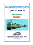
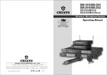
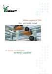
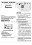
1
Caution and tips on how to obtain the best results.
1.Before inserting the batteries, please make sure that they are inserted according to
the correct polarity.
2.For PLL 16 frequencies agile version, before operation please make sure that the
corresponding receiver MUST have the same frequency group and channel number
as the transmitter.
3.Before making any channel change,please switch off the power supply.The synthesized
program works in such a way that a change of channel will only take place after a power
off and on action. Otherwise, the previously selected frequency will stay unchanged.
4.After making a channel change, please make sure that the corresponding change is
made on the matching receiver also. To be exact, changes MUST be made at both the
transmitter and receiver.
5.The audio cable of VHF transmitters also serve as antenna. The length of the cable is
cut according to the specific frequency range. Do not alter the length or mix around
the cable of different transmitters. The use of wrong audio cable will affect the antenna
efficiency of the transmitter!
6.Use only brand new Alkaline batteries. Do not use " general purpose " batteries.When
batteries are weak, replace the all batteries at the same time. Do not mix and use new
and old batteries together.
7.Position the receiver such that it has the least possible obstructions between it and the
transmitter. Line of sight is bes !
8.The transmitter and the receiver should be as close as possible but not less than 1m.
9..A receiver cannot receive signals from two or more transmitters simultaneously.
10.Turn the transmitter off when it is not in use. Remove the batteries if it is not to be
used for a period of time.
11. Antennas form an integral part of the receiver and must be installed when in operation.
Challenger 1000 / Challenger Slave
Operation Manual
Congratulation and thank you for purchasing this all-in-one state-of-the-art
portable sound system. To ensure a trouble free operation, please go through
this manual thoroughly to fully understand its controls and functions.
The following table gives an overview of the various Challenger 1000 versions :
VERSION
UHF
VHF
U1DR
U1TR
U2DR
U2TR
V1DR
V1TR
V2DR
V2TR
Legend :
U : UHF
V : VHF
D : CD
T : TAPE
NO. OF
TAPE
CHANNEL ( T )
CD
(D)
AC
BATTERY AUDIO
(R)
LINK
1
1
2
2
1
1
2
2
Yes:
No:
R : Rechargeable
Example : U2DR denotes UHF 2 channel with CD and Rechargeable battery.
*Audio Link is standard in the Basic System.
Note : Manufacturer reserves the rights to change the above combinations
without prior notice.
Remark : At present, the standard receiver module offered is the UHF 16
channel selectable version. In future, various versions of VHF / UHF model
will also be offered as options.
20
1
CHALLENGER1000
(CD version configuration )
Installation of cable restraint
To prevent contact noise caused by constant tension applied to
the connector,,a cable
restraint is designed such that tension is totally reduced when
it is properly used.
When the audio cable go through the cable restraint,it could
prevent sweatfrom going diectly into the electronic board via
the connector.
This is another advantage of the cable restraint.
26
26
30
28
27
30
29
28
27
29
1
LCD Display
Repeat
Shuffle
Play/Pause
Stop
disc
F-skip/FF
B-skip/Review
Mode selector
Eject
COMPACT DISC PLAYER
Installation of Lavalier /
Headset microphones or instrument inputs
Depending on customer requirements, Lavalier / Headset microphone or instrument
inputs could be connected to the transmitter via the audio input connector. User is free
to choose the various input sources but is advised to take note that connector used must
be compatible to each other. The pin configurations of mini XLR connector are as follow
( Fig.1 ).
mini XLR connector
LED INDICATOR
GT IN
OFF
1
2
3
4
5
6
7
8
9
10
11
12
13
15 16
ON
2
3 4 1
POWER
ANTENNA
MT IN GND
POWER
SWITCH
PHANTOM POWER
Fig. 1
14
Input Level Gain Control Adjustment
20
17
Low impedance ( Lo-Z ) " MT" & high impedance ( Hi-Z ) " GT" gain controls are situated
inside the transmitter as shown in Fig 10. Gain controls are adjustment ports that enable
you to use microphones of differing output levels and Guitar or instruments with Hi-Z
output. To adjust microphone ( Lo-Z ) input levels, turn the " MT" control and to adjust
the Guitar or instrument ( Hi-Z ) input, adjust the " GT" gain control to set the transmitter's
desired audio input level.
18
19
Fig. 1
2
19
CHALLENGER1000
(TAPE version configuration )
Installation of Belt-clip
This specially designed detachable belt-clip allows the user to wear the transmitter
with antenna pointing upward or downward as illustrated. To wear the transmitter with
the transmitter pointing upward, install the belt-clip as in Fig.4. To wear the transmitter
with the antenna pointing downward, please install the belt-clip as in Fig,5.
Charging points
26
26
30
28
27
Fig. 4
30
29
29
28
27
Fig. 5
Eject key
Counter
Charging points
Variable Speed control
Auto reverse indicator
Single reverse indicator
Single side indicator
Mode selector
Fast forward
Forward play
Stop
Reverse play
Fast reverse
Channel selection and gain adjust
Channel selector and gain adjust are hidden in the designated cover in the front as
shown in picture.
To make channel selection and gain adjust, please press the designated cover and flip
it open as shown.
Channel selection can be made by
rotating the selector with a small
SM-916
screw driver.
Gain adjust for Lavalier and Headset
microphones can be done by adjusting
the MT switch, whereas GT switch is
for the gain adjust of electric Guitar
MT
and other high impedance line level
Channel
SM-816
inputs.
Selector
1
2
3
5
4
Record
6
7
11
8
9
12
10
14
13
15 16
GT
20
17
CH SW
3
12 13 14 1 5
16 1 2
11
7
8 9 10
MT
19
4 5 6
GT
18
Channel selection
Channel selection is possible only for SM-816 plus transmitters. To change channel,
please open the battery cover and access the rotary switch to select channel with a
small screw driver.
18
Fig. 2
3
CHALLENGER1000
(SLAVE configuration)
Installation of batteries( SM-916)
Installation of batteries( SM-816 PLUS)
21
22
23
Fig. 3
4
17
CHALLENGER1000
(Companion speaker)
Belt-Pack Transmitter (SM-816PLUS/SM-916)
Antenna
Battery status
Indicator
Power switch
SM-816PLUS
Audio input
Connector
Cable restraint
Battery
Compartment
Charging points
Capsuale
Mike clip
Line Control
Antenna
Battery status
Indicator
Power switch
Audio input
Connector
Cable restraint
Battery Compartment
SM-916
24
25
Capsuale
Mike clip
Line Control
Fig. 4
16
5
Challenger 1000
Rear panel configuration ( Fig. 1 & Fig. 2 )
The rear panel is divided into three different sections as follow :
A.Compartment for receiver modules
B.CD player / Cassette Recorder
C.Controls
Sensitivity switch
Receiver modules compartment
At present, the standard receiver module offered is the 16 channel selectable
UHF receiver module.
PLL synthesized 16 channel receiver module(26)
Power ON & Volume Control (30)
Power ON indicator (29)
Channel selector (27)
Diversity A / B ( RF ) indicator (28)
In future, different versions of VHF / UHF receiver module will also be available.
TAPE / CD control
Power ON switch and Volume control for Tape / CD player ( 3 ).
Changing of capsule
AUDIO LINK active out
Active Out jack ( 8 ) to SLAVE unit. Maximum number of SLAVE units to be
connected with a MASTER in daisy chain is about 20.
LINE IN / LINE OUT
Standard RCA jack for LINE IN / OUT ( 9 ).
LINE IN volume control ( 4 )
TONE control
Tone control for Bass / Treble adjust ( 5 ) for TAPE / CD.
MASTER Volume Control ( 10 )
It controls the mixed output volume of the MASTER unit as well as all the following
SLAVE units.
Power Supply and Output controls
This section is identical for both Challenger 1000 ( Master ) and the Challenger Slave.
Main Power switch ( 17 )
Power Supply ( weak battery ) indicator RED ( 15 ).
Power Supply ( good battery ) indicator GREEN ( 16 ).
Voice Priority ( Ducking ) switch ( 18 ) ( not available for Challenger Slave ).
90 ~ 260 V AC IN jack ( 19 )
Charging indicator ( 20 )
Speaker out ( unswitched ) ( 12 )
Speaker out ( switched ) ( 11 )
24V ~ 32 V DC IN jack ( 13 )
5A Fuse holder ( 14 )
6
Operating instructions
1.Before operation, please check and make sure that transmitter & receiver are
of matching frequency or frequency group (for PLL version). For PLL version,
further verify that the channel selected at both ends are of the same.
2.To switch on the microphone, put the switch to "ON" position. The green LED
indicator will light on indicates that battery is fresh. When RED LED light on
indicates that battery is weak, thus a replacement is necessary.
3.For best result, alkaline battery is recommended. Please remove the battery
if the transmitter is not to be used for a longer period.
4.When necessary, mic capsule could be replaced by pulling out and plugging
in the new one, either dynamic or condenser for SQ-916.
15
Challenger Slave
Hand-held microphone
The Challenger Slave is an active ( powered ) speaker unit with built-in
switching power supply as well as rechargeable batteries, complete with
similar charging circuit as that of the Challenger 1000 Master unit.
It is an extended and indispensable member of the Challenger Audio Link
system.
Audio Link Active Bus controls
1 .A c t i v e b u s I N ( 2 1 )
2 .A c t i v e b u s O U T ( 2 2 )
3 .S l a v e v o l u m e c o n t r o l ( 2 3 )
Challenger Speaker ( C-SP )
The Challenger Speaker is a passive companion speaker for the
Challenger 1000 series.
It is for connection to the switched or unswitched speaker outs of the
Challenger 1000 ( Master ) or the Challenger Slave units.
Rear panel configuration.
1 .S p e a k e r I N ( 2 4 )
2 .S p e a k e r O U T ( 2 5 )
Mechanical Parts
Battery
All the Challenger 1000 ( Master ), Challenger Slave and the
Challenger companion speaker enclosures have the identical
mechanical parts as follow :
Three stages Trolley ( 31 )
Trolley release button ( 32 )
Wheels ( 33 )
Handle ( 34 )
Tripod mount bracket ( 35 )
( not application for Challenger Slave and companion speaker )
34
32
31
33
Pre
ss
35
14
Remark : Please be advised that the trolley and wheels are meant for moving around on smooth
surface and short distance only. It is NOT meant or built for heavy duty long distance
transportation or on rough surfaces. Please DO NOT use the trolley as handle for going
up and down the staircase. For going up and down the staircase, please use the Handle ( 34 ).
7
Operating procedures
Simple DIY Trouble-shooting :
After unpacking the unit for the first time, please charge the rechargeable batteries first for about 10 to 15
hours before any operation. The batteries were fully charged in the factory before shipment. However,
the unit you have just unpacked could have been several months after the shipment and the rechargeable
batteries might have been fully discharged naturally.
To charge the batteries, just plug in the AC supply and charging will start automatically.
In the charging process, charging indicator LED ( 20 ) will be RED.
When GREEN LED appears on the charging indicator ( 20 ), batteries are
fully charged and normal operation could now be started.
To operate using the rechargeable batteries, switch on the main power supply switch ( 17 ).
When batteries are charged, power supply GREEN indicator (16 ) will be lighted up.
The main power supply DOES NOT switch on the built-in cassette recorder or the CD player
module as well as the receiver modules. They have their own individual power on switch.
To operate the cassette deck or CD player, please switch on the TAPE / CD switch ( 3 ).
To operate the receiver module, please switch on the power on switch on each receiver module front
panel ( 30 ).
When the power supply RED indicator (15) is lighted up instead, it means the built-in batteries are weak.
Please charge the batteries first before usage ( for the very first time or the unit has not been used for
a long time ) or you could also operate it while charging. The AC power supply is designed such that it
also provides the power for the system while charging the batteries.
Operating the Wireless Microphone System.
To use the 1st wireless system, first switch on the receiver power supply switch (30) on the receiver
control panel. Make sure that master volume control are set to minimum level before turning the receiver
unit on. After switching on the receiver, set the master volume control (10 ) to mid level. Switch on the
corresponding matching transmitter or handheld microphone ( please refer to the operating instruction
of the individual transmitter ).
When RF signal is being received by the receiver, the receiver RF diversity signal indicator A or B (28 )
on the control panel will light up. Rotate the volume control knob (30) on receiver module clockwise to
the desired levels. When voice is spoken into the microphone, amplified sound should be heard over
the built-in speaker. When operating the wireless microphone, please ensure that the correct channel
appear on both the transmitter and receiver.
To use the 2nd wireless system, repeat the above procedure on the 2nd receiver module and the corresponding transmitter.
Operating the Wired / Cable Microphone
To use the first wired microphone, simply plug in the wired microphone into the MIC 1 XLR / Phone
jack combo connector ( 6 ) on the control panel. This unique connector accepts both XLR and 1/4 "
Phone Jack male connector. Set the Master volume control ( 10 ) to mid level, rotate the volume
control ( 1 ) clockwise on MIC 1 to increase the volume.
When voice is spoken into the wired microphone, amplified sound should be heard over the built-in
speaker.
To use the second wired microphone, simply plug in the wired microphone into the XLR / Phone jack
combo connector ( 7 ) on MIC 2 and repeat the above procedure with MIC 2 volume control ( 2 ).
No sound when one speaks to the wireless microphone
Please verify the followings:
1.Main power switch of the system should be ON. When power on LED not lighted up, it
means that the battery is either weak or not charged. Please plug in the AC cable to charge
the battery. The rechargeable battery has a life span of about 2 years. If the batteries have
reached their life expectancy, please change them to a fresh pair.
2.The power switch of the corresponding receiver module should be put to ON. This is in
dicated by the lighted power LED. When two wireless mikes are used, both power
switches of the receiver modules must be ON.
3.Wireless mike should be switched ON and verify that the battery is o.k.
( please refer to wireless microphone operating manual ).
4.Please verify that the frequency on the wireless microphone and the corresponding
built-in wireless receiver module are exactly the same frequency group and channel.
5.Master volume control of the system should be turned on.
No sound when Cassette / CD player is used.
Main power switch should be ON. When no light appear, it means that the battery is weak.
Please plug in the AC cable to charge the battery.
Tape / CD volume control is turned on but Master volume control not on.
Ducking ( Voice Priority ) does not work
Please ensure that the Voice Priority switch is put to ON position to activate the
ducking circuitry.
Audio Link does not work
Only one OUT cable is connected from the MASTER to the IN jack of the 1st SLAVE unit.
The OUT of the 1st SLAVE goes to the IN of the next SLAVE and so on.
No power supply
1.Battery is faulty
2.Battery is not charged.
Installation of Receiver module
To install the receiver module, first remove the blank panel covering the module
compartment, position the module such that it fit exactly into the guide rail in the module
compartment and push it to the end so that the gold finger connection plug firmly fit into
the socket provided. To secure the receiver module to the Challenger rear panel, tighten
the receiver panel with two screws.
To remove the receiver module, first unscrew the two screws on the module front panel,
pull up the trolley, follow instruction as shown in the picture and push out the module with
a screw driver.
2
1
Both wired and wireless microphones could be used simultaneously as a built-in mixer mixes all the
input signals.
8
13
Battery Charging
Operating the CD player.
Internally, the Challenger 1000 / Challenger Slave contain 2 pcs of 12V / 4.5AH
maintenance-free lead acid rechargeable battery, which has no memory effect.
When the battery is weak, the power indicator ( 15 ) RED LED will be lighted up
when the main power switch is switched on.
To charge the battery, simply plug in the AC power supply, the charging process
will start automatically. While charging, the charging indicator ( 20 ) will be in RED.
When battery is fully charged, the charging indicator ( 20 ) will stay GREEN.
To begin operation, first switch on the TAPE / CD Power switch ( 3 ).
Speaker out ( unswitched ) ( 12 )
PLAY / PAUSE
SHUFFLE
STOP
When an external speaker is connected to this output, both the internal speaker
of Challenger 1000 and the external speaker will have sound.
REV-SKIP
Speaker Out ( switched ) ( 11 )
When an external speaker is connected to this output, the internal speaker of
Challenger 1000 will be muted and only the external speaker will have sound.
Trolley release button ( 32 )
SKIP-FWD
This button serves to release the locking mechanism of the trolley. To pull out the
first stage of the handle, one does not need to press the button to release it.
To pull the second and third stages of the handle, press the release button to
unlock the mechanism.
To put back the handle, press the release button to unlock the mechanism and
return the handle to its original position.
REPEAT/ENTER
EJECT
Specification
Item
Max. Power Output
Distortion
Frequency Response
Input
Speaker System
Bass Speaker
Tweeter
Power Supply
Charging Time
Receiver Module
Wired microphone
Wireless microphone
Output
Dimension
Weight
Color
Specification
Max. 75W (RMS) / 4 Load
< 0.5%
50HZ-20KHZ +/-3db
Wireless receiver/ CD/ TAPE/ Wired Mic / Line In
3-Ways full range
10"8 100W/ 97db at 1W/ 1m
AC 90-260V switching power
10-15 Hour
UHF/ VHF band
Chiayo or other compatible brand
Handheld/ Lavalier/ Headset
Speaker/ Speaker out(switched)/ Line out
400*350*300mm
18.5kg(TAPE) 17.5kg(CD)
Black
12
PROGP
When it is pressed during STOP, PLAY will start after track search.
When it is pressed during PLAY, it will change to PAUSE mode.
When it is pressed during PAUSE, it will change to PLAY mode.
Press SHUFFLE to play the track randomly, the whole CD tracks will be
played once. Press SHUFFLE again to clear the programming.
When it is pressed at PLAY mode, CD will STOP.
When CD is STOP, pressed this key once to decrease one track.
When CD is in PLAY mode, press this key for < 1/2 second will make it
search backward one track.
When CD is in PLAY mode, press this key for >1/2 second will make it
to execute FR Fast Reverse function.
When CD is STOP, pressed this key once to increase one track.
When CD is in PLAY mode, press this key for <1/2 second will make it
search forward one track.
When CD is in PLAY mode, press this key for >1/2 second will make it
to perform the FF Fast Forward function.
If this key is pressed in cyclical sequence, REPEAT mode will change
as follow :
"REPEAT" : repeat the same track.
" REPEAT ALL" : repeat all tracks.
When this key is pressed at either PLAY or STOP mode, door will move
in and out cyclically.
Programming procedures :
Select the track by pressing B-SKIP / REW or F-SKIP / FF key to select
the desired track and then press REPEAT/ENTER to store. This could be
repeated to store a few programmed track. Press PLAY to perform the
programmed tracks. Press PROGRAM again to clear the programming.
Rotate the volume control knob ( 3 ) of the TAPE / CD control panel to adjust thevolume of the
CD player. For Bass and Treble setting , adjust TONE control ( 5 ) .
Clockwise from center line is to boost Treble and counter-clockwise direction from center line
is to boost Bass.
Caution: This CD player does not accept CD-R and 8cm diameter CD. Either one will
cause malfunction to this CD player.
9
Operating the Cassette Recorder
Audio Link Operation
Schematic diagram
To begin operation., first switch on the TAPE / CD Power On switch ( 3 ).
Keys
MASTER
SLAVE
SLAVE
Audio Link Connection Plan
SLAVE
SLAVE
FF Fast Forward
FP Forward Play
Stop
RP Reverse Play
FR Fast Reverse
Record
Mode selector
SLAVE
SLAVE
The Challenger 1000 could be operated asMASTER only. The Challenger Slave
can only be operated as SLAVE.
In order to operate Audio Link, you must have a Challenger 1000 unitthat operates
as a MASTER . Only one unit is allowed to act as MASTER and the other(s) MUST operate
as SLAVE(s). A MASTER unit is capable of connecting up toabout 20 SLAVE units.
For Active.
To operate Audio Link, connect theActive Output ( 8 ) jack of the MASTER to the
Audio Link IN ( 21 ) jack of the 1st SLAVE unit. The Out jack ( 22 ) of this SLAVE
should be connected to the Input jack ( 21 ) of the 2nd SLAVE unit. Similar connection
shall continue as such for the following SLAVE units.
Volume Control ( 10 ) for MASTER or ( 23 ) for slave.
When used on the MASTER, it controls the MASTER as wellas all the SLAVE units.
When used on the SLAVE unit, it only controls that particular SLAVEunit volume.
Maximum number of SLAVEunits to be connected with a MASTER is about 20.
Speed Control
Eject
Functions
Press this key for fast forward .
Press this key for play in forward direction.
Press this key to stop the tape.
Press this key for play in reverse direction.
Press this key for fast reverse.
Press this key together with FP or RP key for recording.
This key is pressed to select one of the following three modes.
Active in Forward nor Reverse direction, the cassette tape will
play to the end and stop automatically. This mode may be used
for Record and Play.
The cassette tape will play to the end, stop, reverse direction to
the end of the second side and stop. This mode may be used for
Record and Play.
This mode provides continuous " Play " operation. It is not operable
in Record mode, however, it will record one complete cycle if the
recording is begun in the Forward direction.
Normal tape speed at center position. Clockwise direction increases
tape speed. Counter-clockwise direction reduces tape speed.
This key is pressed for ejecting the tape.
Rotate the volume control knob ( 3 ) of the TAPE / CD control panel to adjust the volume of the
Cassette deck. For Bass and Treble setting, adjust TONE control ( 5 ) . Clockwise direction from
centre line is to boost Treble and counter-clockwise direction from center line is to boost Bass.
Voice Priority ( Ducking ) operation
Voice Priority ( Voice overrides Music ) operation is only necessary when Tape
or CD is playing. When the Voice Priority switch ( 18 ) is put to ON position, the
ducking function will be activated. While the music is playing, a voice input from
either a Wired or Wireless Microphone will temporary turn down the volume of
the background music and voice could be heard clearly. Background music will
return to its original setting when no audio input is entering the microphone for
a certain time. However, if the microphone is not switch off, the reentering of
music into the microphone will also activate the voice priority function. So,
Voice priority is best operated using microphones with on / off switch.
However, in an aerobic application, Voice Priority should NOT be activated !
10
11