1
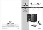
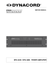
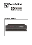
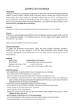
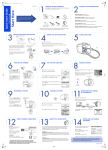
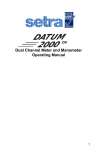
PROFESSIONAL LASER SHOW SYSTEM
DIFFRACTION LASER
G018ED
MANUAL AND USER GUIDE
Distributed By;
Electrovision Ltd.
Lancots Lane.
Sutton Oak.
St. Helens
WA9 3EX
UK
www.electrovision.co.uk
GENERAL INSTRUCTIONS
IMPORTANT NOTE
!
This manual / user guide is part of the product and should be retained with the unit for future reference and passed on with the
product if sold on. Please carefully read this manual / user guide
before use.
!
Unpacking Your Laser
The box should contain the following items;
1 x Diffraction Laser
1 x Mains Lead
1 x Manual / User Guide
Please examine the product carefully and if any damage is found DO NOT use and
contact your supplier immediately to report the damage.
Warnings
1.
This is a class 3B laser product. It is intended for professional use only and
is not a domestic product.
2. Always use your laser in accordance with the GUIDANCE laid down in HS(G)95
“The Radiation Safety of Lasers Used for Display purposes”. This is published
by the UK Health and Safety Executive.
3. There are no user serviceable parts in this product. All servicing and repairs
must be undertaken by a competent engineer.
4. This product must be earthed.
5. For Indoor Use Only.
6. Avoid contact with water and other liquids and away from extremes of heat
and cold.
7. Store in a cool dry place.
8. Always replace the fuse with the same size and value, see label on product for
exact type.
9. Clean only with a damp cloth. DO NOT use detergents or other cleaning agents.
10. Do not drop or knock this product.
PAGE 2
Do’s and Dont’s
1.
2.
3.
4.
Do Not switch the product on and off continuously. This can damage the
product.
To increase the life of the laser diodes use the product in short 10 minute
bursts. Do not run the laser for more than 4 hours continuously. This will
seriously shorten the life of the diodes.
Do Not drop or knock the product. Always transport the unit in a robust case.
Make sure the unit is securely positioned before use.
FRONT PANEL
MIC
2. MICROPHONE
MIC LED
POWER LED
3. SOUND ACTIVE LED BLUE
4. POWER LED RED
1. LASER APATURE
LASER RADIATION
AVOID EXPOSURE TO BEAM
CLASS 3B LASER PRODUCT
G018ED
DIAG. 1
REAR PANEL
5. DIP SWITCHES
SENSITIVITY
1. AUDIO SENSITIVITY
KNOB
FUNCTION SETTING
ON
MIN
MAX
DP
6. DMX SIGNAL INDICATOR :
GREEN. THE LED WILL FLASH
ON RECEIVING DMX OR
MASTER-SLAVE SIGNAL
1 2 3 4 5 6 7 8 9 10
IN
7. DMX OR LINK VIA XLR
2. COOLING FAN
OUT
DMX LINKING
ON
3. IEC POWER INLET
8. ON / OFF SWITCH
I
POWER
230V~F2A
0
OFF
4. FUSE HOLDER
DIAG. 2
PAGE 3
FUNCTIONS AND SETTINGS
Your laser can be controlled from several sources all of which can be accessed using
the dip switch panel on the rear of the unit (see Diag 2).
Sound Activated
For sound activated operation follow the instructions below.
TIVATED AND
IT RUNNING IN
DE
1.
2.
ON
DP
1 2 3 4 5 6 7 8 9 10
Set DIP switches to above settings.
Use the sound adjustment
knob on the rear
of the product to increase /
ON
DP
decrease the sound sensitivity of the product to the sound level.
AND MASTER
AUTO MODE
1 2 3 4 5 6 7 8 9 10
NOTES
CTIVATED
AND
ONwill switch off after 8DP
When in this mode the laser
seconds if the sound stops or
falls
below
the
preset
level.
The
laser
will
start
when
the sound starts.
NIT RUNNING IN ON
DP
1 2 3 4 5 6 7 8 9 10
SLAVE
1
ODE
Auto Mode
DE AND MASTER
N AUTO
SLAVEMODE
2
1.
2.
1 2 3 4 5 6 7 8 9 10
ON
DP
ON
DP
1 2 3 4 5 6 7 8 9 10
1 2 3 4 5 6 7 8 9 10
Set DIP switches to above settings.
The product will now
cycle through a selection
ON
DPof built-in programs.
OUND ACTIVATEDON
AND
ON DP
DP
SLAVE
1
SLAVE
3
Master
Slave
Mode
MASTER UNIT RUNNING
1 32IN
4 65 7
68
7 8 9 10
12
43 5
1 293104 5 6 7 8 9 10
OUND
MODE
Set master
unit using appropriate DIP switch settings below.
ONON
DPDP
SLAVE
ON
DP
SLAVE
4 2AND
Master
DIP switch
setting for
UTO
MODE
MASTER
1 32 43 5
4 65 7
68
79
819
running in AUTO Mode.
0 10
12
UNNING IN AUTO MODE
1 2 3 4 5 6 7 8 9 10
ON
ON
Master
setting for
OUND
ACTIVATED
SLAVE
3 DIP switchAND
ON
DP
DP
DP
running in Sound To1Light
DP
SlaveUNIT
2IN
3 4 5 6ON
7 8 9 10
ASTER
Mode. RUNNING
SLAVE
1
1 2 3 4 5 6 718293104 5 6 7 8 9 10
OUND
MODE
ON
1234
DP5 6 7 8 9 10
PAGE 4
SLAVE 4
SLAVE 4
1 2 3 4 5 6 7 8 9 10
ON
Slave Settings
Slave
DP
1 2 3 4 5 6 7 8 9 10
1.
The first laser in the chain is the master. The dip switch settings should be set
as per the settings shown on the opposite page.
The next laser(s) in the chain are the slave units. They should be set as per the
slave settings shown above.
Link the units together using high quality 3 pin DMX cable (see Diag 3).
Switch on the units in order of connection.
2.
3.
4.
SENSITIVITY
FUNCTION SETTING
ON
MIN
MAX
FUNCTION SETTING
ON
DP
MIN
1 2 3 4 5 6 7 8 9 10
MAX
SENSITIVITY
DP
IN
OUT
DMX LINKING
DMX LINKING
ON
ON
ON
I
I
OFF
POWER
230V~F2A
MASTER
0
I
OFF
0
POWER
230V~F2A
OFF
POWER
POWER
POWER
DP
1 2 3 4 5 6 7 8 9 10
OUT
OUT
DMX LINKING
0
MAX
IN
IN
POWER
230V~F2A
FUNCTION SETTING
ON
MIN
1 2 3 4 5 6 7 8 9 10
SLAVE 1
SLAVE 2
DIAG. 3
NOTES
1.
2.
3.
Upto 32 units can be connected together in this way. Always use high quality 3
pin DMX leads and use a DMX terminator on the last unit in the chain.
The slave units will mimic the master unit.
When in this mode and operating to sound you will need to adjust the
sensitivity of the master unit only.
External DMX 512 Control
The unit can be controlled by most standard DMX512 controller. Always read the
controller user manual before attempting to use the laser.
To use the lasers with a DMX controller they will need to be linked together using
high quality 3 pin DMX cable (see Diag 4).
For setup follow instructions below;
1.
For DMX mode an address must be set on each unit between the values of 1
and 512. To set an address using the dip switches you add together the values
PAGE 5
of the switches (see Diag 6) turned on . Therfore to set channel 1 you would
turn switch 1 on and all others off (see Diag 7). For the second unit in the
chain if you wish to have it do the same as the first unit you would give it the
same DMX address otherwise you will need to allocate 5 channels for number
1 so the next unit must have an address of 6 which is dip switches 2 and 3 ON
(see Diag 7). You would continue on till all units have been addressed.
Site the units securely before connecting and powering up.
Connect the units and the controller before switching the power on. Always
use high quality DMX leads and use a DMX terninator on the final unit in the
chain.
Upto 32 units can be connected together in a single chain.
2.
3.
4.
SENSITIVITY
FUNCTION SETTING
ON
MIN
MAX
FUNCTION SETTING
ON
DP
MIN
1 2 3 4 5 6 7 8 9 10
IN
MAX
SENSITIVITY
ON
MIN
DP
1 2 3 4 5 6 7 8 9 10
IN
OUT
OUT
OUT
DMX LINKING
DMX LINKING
ON
ON
ON
I
I
0
MAX
IN
DMX 512
DMX LINKING
POWER
230V~F2A
FUNCTION SETTING
DP
1 2 3 4 5 6 7 8 9 10
OFF
0
POWER
230V~F2A
I
OFF
DMX UNIT 1
0
OFF
POWER
POWER
POWER
POWER
230V~F2A
DMX UNIT 2
DMX UNIT 3
DIAG. 4
Channel
CH1
Function
Mode
Value
Description
0 - 49
Laser OFF
50 - 99
DMX Mode
100 - 149
Sound Actvated Mode
150 - 255
AUTO Mode
0 - 99
CH2
Running Direction
Clockwise Rotation
100 - 199
No Rotation
200 - 255
Counter Clockwise Rotation
CH3
Running Speed
0 - 255
0 Fast, 255 Slow
CH4
Twinkle Speed
0 - 255
0 Fast, 255 Slow
0 - 99
Red + Green
CH5
Colour Selection
100 - 199
Red
200 - 255
Green
Note : When CH1 is set to DMX (value 50 -100), CH2,CH3,CH4 and CH5 can be used otherwise altering
CH2,CH3,CH4 and CH5 has no effect.
DIAG. 5
PAGE 6
MASTER UNIT RUNNING IN
1 2AUTO
3 4 5 6MODE
7 8 9 10
RUNNING IN
SOUND MODE
OUND ACTIVATED AND
ON
DP
ON
DP
AUTO
MASTER
1=ON X=ON OR OFF
MASTER UNIT RUNNING
IN MODE AND0=OFF
SLAVE 1
DIPSWITCH
1 2
3 4 5 6MODE
7CHART
8 9 10
RUNNING IN
AUTO
OUND MODE
1 2 3 4 5 6 7 8 9 10
#1
#2
#3
#4
#5
#6
#7
#8
#9
#10
ND
ON
DP
ON
DP
UTO
MODE
AND
MASTER
1
2
4
8
16
32
64 ON128
256 DMXDPOFF
G IN
SLAVE 2
3 4 5 6MODE
7 8 9 10
SLAVE 1
UNNING 1IN2AUTO
TER
DE
X
X
X
X 1 2 3X4 5 6 7X 8 9 10 X
ONX
X
X DP
X
X
ON
X
X
DP
SET DMX ADDRESS FOR DMX MODE
SLAVE 1
1 2 3 4 5 6 7 8 9 10
ON
SLAVE 2
DP
1 2 3 4 5 6 7 8 9 10
ON
DMX Address 1
SLAVE 3
DP
1 2 3 4 5 6 7 8 9 10
SLAVE 2
X
0
1
X
1
1
1 2 3 4 5 6 7 8 9 10
ON
SLAVE 3
DP
0
1 2 3 4 5 6 7 8 9 10
1 2 3 4 5 6 7 8 9 10DIAG. 6
ON
SLAVE 3
DP
1 2 3 4 5 6 7 8 9 10
ON
DMX Address 6
SLAVE 4
ON
SLAVE 4
DP
DMX Address 11DP
Slave
0
0
1ON 1
0
1
11 2 03 4
160
161
162
163
164
165
166
167
168
169
170
171
172
173
174
175
176
177
178
179
180
181
182
183
184
185
186
187
188
189
190
191
192
193
194
195
196
197
198
199
200
201
202
203
204
205
206
207
208
209
210
211
212
213
214
215
216
217
218
219
220
221
222
223
0
1
1
5
1 6
224
225
226
227
228
229
230
231
232
233
234
235
236
237
238
239
240
241
242
243
244
245
246
247
248
249
250
251
252
253
254
255
1
0
0
70 8
256
257
258
259
260
261
262
263
264
265
266
267
268
269
270
271
272
273
274
275
276
277
278
279
280
281
282
283
284
285
286
287
DP
FUNCTION
1 2 3 4 5 6 7 8 9 10
ON
DMX VALUE
DP
SOUND ACTIVATED
1 2 3 4 5 6 7 8 9 10
ON
AUTO MODE
DMX SLAVE
DP
1 2 3 4 5 6 7 8 9 10
ON
ON
1 2 3 4 5DMX
6 7 QUICK
8 9 10REFERANCE
1 2 3 CHART
4 5 6 7 8 9 10
#9
0
0
0
0
0
ONDMX : DIPSWITCH SETDP
ON
DP
0=OFF
#8
0
0
0
0
1
SLAVE
4
1=ON
#7
0
0Slave
1
1
0
1 2 3X=OFF
4 5 OR
6 7ON
8 9 10
1 2 3 4 5 6 7 8 9 10
#6
0
1
0
1
0
#1 #2 #3 #4 DP
#5
ON
ON
0
0
0
0
0
32 64 96 DP
128
Slave
1
0
0
0
0
33 65 97 129
1
1 2 3 4 5 6 7 8 9 10
1 22 3 34
4 5 6667 8989 10130
0
1
0
0
0
1
1
0
0
0
3
35
67 99 131
ON
DP
0
0
1
0
0
4
36 68 100 132
1
0
1
0
0
5
37 69 101 133
1 2 3 4 5 6 7 8 9 10
0
1
1
0
0
6
38 70 102 134
1
1
1
0
0
7
39 71 103 135
0
0
0
1
0
8
40 72 104 136
1
0
0
1
0
9
41 73 105 137
0
1
0
1
0
10 42 74 106 138
1
1
0
1
0
11 43 75 107 139
0
0
1
1
0
12 44 76 108 140
1
0
1
1
0
13 45 77 109 141
0
1
1
1
0
14 46 78 110 142
1
1
1
1
0
15 47 79 111 143
0
0
0
0
1
16 48 80 112 144
1
0
0
0
1
17 49 81 113 145
0
1
0
0
1
18 50 82 114 146
1
1
0
0
1
19 51 83 115 147
0
0
1
0
1
20 52 84 116 148
1
0
1
0
1
21 53 85 117 149
0
1
1
0
1
22 54 86 118 150
1
1
1
0
1
23 55 87 119 151
0
0
0
1
1
24 56 88 120 152
1
0
0
1
1
25 57 89 121 153
0
1
0
1
1
26 58 90 122 154
1
1
0
1
1
27 59 91 123 155
0
0
1
1
1
28 60 92 124 156
1
0
1
1
1
29 61 93 125 157
0
1
1
1
1
30 62 94 126 158
1
1
1
1
1
31 63 95 127 159
ON
DP
1 2 3 4 5 6 7 8 9 10
1 2 3 4 5 6 7 8 9 10
DPDIAG. ON
7
1 2 3 4 5 6 7 8 9 10
DMX Address 16
DP
1
1
0DP 0
0
1
9110 0
1 2
1
0
1
1
3 4 5 6 7 8 9 10
1
1
1
1
1
1
1
1
0
0
1
1
0
1
0
1
288
289
290
291
292
293
294
295
296
297
298
299
300
301
302
303
304
305
306
307
308
309
310
311
312
313
314
315
316
317
318
319
352
353
354
355
356
357
358
359
360
361
362
363
364
365
366
367
368
369
370
371
372
373
374
375
376
377
378
379
380
381
382
383
384
385
386
389
390
391
392
393
394
395
396
397
398
399
400
401
402
403
404
405
406
407
408
409
410
411
412
413
414
415
416
417
320
321
322
323
324
325
326
327
328
329
330
331
332
333
334
335
336
337
338
339
340
341
342
343
344
345
346
347
348
349
350
351
416
417
418
419
420
421
422
423
424
425
426
427
428
429
430
431
432
433
434
435
436
437
438
439
440
441
442
443
444
445
446
447
448
449
450
451
452
453
454
455
456
457
458
459
460
461
462
463
464
465
466
467
468
469
470
471
472
473
474
475
476
477
478
479
480
481
482
483
484
485
486
487
488
489
490
491
492
493
494
495
496
497
498
499
500
501
502
503
504
505
506
507
508
509
510
511
PAGE 7
TECHNICAL SPECIFICATIONS
VOLTAGE..............................................................................................230V~50HZ 20W
FUSE............................................................................................F2A/250V 5 x 20 mm
LASERS......................................................................................532nm / 50mW Green
.........................................................................................650nm / 100mW Red
WORKING MODES .....................................Sound Activated, DMX, AUTO, Master-Slave
INTERFACES..................................................3 Pin XLR for DMX / Master-Slave linking
EFFECTS ...............................................................................................Over 500 Beams
DIMENSIONS ..................................................................................100x 300 x 200mm
WEIGHT.................................................................................................................3.2Kg
WARNING
THIS PRODUCT IS FOR PROFESSIONAL USE ONLY
This product is a Class 3B laser product and emits hazardous levels of laser radiation, will cause serious injury to the eyes if viewed directly. It should only be used
in accordance with the guidance given in HS(G)95: "The Radiation Safety of Lasers
used for Display Purposes", published by the UK Health & Safety Executive . Any applicable local safety requirements must also be met
PAGE 8