1
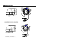
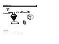
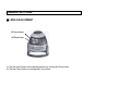
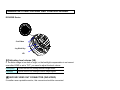
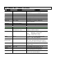
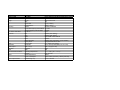
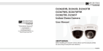
5436 W Crenshaw Street
Tampa, FL 33634
www.digital-watchdog.com
Technical Support : 1-866-446-3595/813-888-9555
INSTRUCTION MANUAL
D2362DIR Series
About manual
Before installing and using the camera, please read this
manual carefully.
Be sure to keep it handy for future reference.
PRECAUTIONS
■ Do not open or modify
Do not open the case except during maintenance and installation,
as it may be dangerous and cause damages.
■ Do not put objects inside the unit
Make sure that no metal objects or flammable substances
get inside the camera. It could cause fire, short-circuits or damages.
■ Be careful when handling the unit
To prevent damage, do not drop the camera or subject it to
strong shock or vibration.
■ Install away from electric or magnetic fields
■ Protect from humidity and dust
■ Protect from high temperature
Be careful when installing close to the ceiling , in a kitchen or boiler
room, as the temperature may rise to high levels.
■ Cleaning
Dirt can be removed from the case only by wiping it with a soft cloth
moistened with a soft detergent solution.
■ Mounting Surface
The mounting surface material must be strong enough to support
the camera.
TROUBLESHOOTING
Before sending the camera out for repair, check the items below.
If the problem persists after checking these items, contact your service
center.
■ If no image appears
Is the coaxial cable attached securely?
Are the power and voltage normal?
Has the iris of the lens inside the camera been
adjusted correctly (with the level volume) ?
Is there adequate illumination?
■ If the image is unclear
Is the lens in focus?
Is the lens dirty?
Dirt or fingerprints on the lens can adversely affect the
images. Gently wipe any dirt or fingerprints off the lens
with a soft cloth or lens cleaning paper and cleaning
fluid (commercially available).
Is the monitor adjusted correctly?
WARNING:
TO PREVENT THE RISK OF FIRE OR ELECTRIC SHOCK, DO NOT EXPOSE
THIS APPLIANCE TO RAIN OR MOISTURE.
DIMENSION (mm)
D2252DIR, D2262DIR, D2362DIR
D2372TIR, D2363TIR Series
INSTALLATION
EC
FE
F
D
D
C
B
A
INSTALLATION (cont.)
1. Loosen
A.
Loosen the
the fixing
fixing screw
screw (A)
using
using
the aL-wrench
screwdriver.
that came with the camera
2. Separate
B.
Separate the
the upper
upper case
case (B)
andand
the the
base
base
case.
case (D).
3. Cut
C.
Cut aa hole
hole in
in the
the ceiling
ceiling for
for routing
routing the
the cables.
cables.
4. Place
D.
Place the
the camera
camera horizontally
horizontally on
on the
the ceiling,
ceiling, drill
drill the
the screw
screw
holes at the marked four positions.
5. Pass
E.
Pass the
the power
power cable
cable (E)
andand
video
video
cable
cable
from
(F)
the
from
camera
the camera
unit through the cable hole in the ceiling.
6. Align the screw holes of the camera unit with the holes in the
F.
ceiling, secure with the four screws.
7. Install
G.
Install and
and adjust
adjust the
the camera
cameraunit.
unit.
8. Adjust
H.
Adjust the
the dome
dome liner
liner to
to show
show the
the lens
lens through
through the
the camera
camera
window
fix toattach
the base(D)
it to the base
window,and
base(D).
base.
9.Put
I.
Putthe
theupper
uppercase
caseand
(B) and
the base
the base
together.
(D) together.
10.Tighten
J.
Tightenthe
thescrews
screw with
(A) for
thethe
L-wrench
upper/base
for the
cases
upper
notand
to be
base not to be
separated .
CONNECTION
DC12V
DC12V / AC24V
CAUTION :
Check for polarity when using a DC 12V power supply.
CAMERA SETTINGS
■ LENS ADJUSTMENT
B. Focus lever
A. Zoom Lever
A. Set the zoom lever to the desired positon by moving the Zoom lever.
B. Set the Focus lever by moving the Focus lever.
CAMERA SETTING FOR SIDE OSD CONTROL BOARD
D2362DIR Series
2'nd Video
Joy Stick Key
VR
(1) Adjusting level volume (VR)
If the entire image is too dark or bright, or the backlight compensation is not correct
even after LENS is set to "DC", you need to adjust the level volume.
CCW (Low)
Closes the lens iris, making the entire image darker
CW(High)
Opens the lens iris, making the entire image brighter
(2) SECOND VIDEO OUT CONNECTOR (2ND VIDEO)
If installer uses a portable monitor, this connector should be connected.
OSD MENU SETTINGS - D2362DIR
SETUP
FUNTION
SUMMARY
LENS
MANUAL, DC
when using BUILT-IN lens,
SHUTTER
ESC, MANUAL, FLK
MANUAL: 1/60(50) ~ 1/120,000sec
WHITE BAL.
ATW, AWC, MANUAL
ATW: 1,800 ~10,500 ˚K
BACKLIGHT
OFF, LOW, MIDDLE, HIGH
Backlight compensation
AGC
OFF, NORMAL, HIGH
the Brightness can be adjusted(1 ~ 70)
DNR
OFF, LOW, MIDDLE, HIGH
SENS-UP
OFF, AUTO
when AGC is turned off, DNR does not
when tAGC is turned off, SENS-UP
SPECIAL
Refer to the bottom
the type of the lens is able to fix
does not operate.
EXIT
Saved all the setting menu, then exits.
SPECIAL
CAMER ID
FUNTION
uppercase or lowercase,
/numeral 0~9/-, null
DAY / NIGHT
COLOR→AUTO→B/W
SUMMARY
maximum length for the name
display is limited 15letters.
AUTO : night time→ B/W mode
day time → color mode ,
B/W
:
Always B/W mode
COLOR : Always color mode
SYNC
INT, LL
LL mode: you can adjust desired phase
MATION
OFF, ON
ON mode: AREA(4 programmable zone)
359˚, auto
detection
ffrom 0˚ ~ 359˚
t d
t ti
DETECTION
the word "MOTION DETECTED" appear
on the screen when movement is detected
PRIVACY
OFF, ON
ON mode:AREA(4 programmable zone ),
MIRROR
OFF, ON
set a horizontal image inversion.
SHARPNESS
OFF, ON
/SIZE/TONE
RESET
the available range of level is 0 ~ 31.
returns to the level which was set
by the manufacturer for shipment.
RERURN
save the SPECIAL MENU and then
returns to the SETUP MENU
WARRANTY INFORMATION
Digital Watchdog (referred to as “the Warrantor”) warrants the Camera Series
against defects in materials or workmanship as follows:
LABOR: For the initial five (5) years from the date of original purchase, if the
camera is determined to be defective, the Warrantor will repair or replace the
unit, with
new or refurbished product at its option, at no charge.
PARTS: In addition, the Warrantor will supply replacement parts for the initial
five (5) years.
To obtain warranty or out of warranty service, please contact a Technical
Support Representative at 1-866-446-3595 Monday through Friday from 9:00
AM to 5:00 PM Eastern.
A purchase receipt or other proof of the date of the original purchase is required
before warranty service is rendered. This warranty only covers failures due to
defects
during
d
f t iin materials
t i l and
d workmanship
k
hi which
hi h arise
i d
i normall use. This
Thi
warranty does not cover damage which occurs in shipment or failures which are
caused by products not supplied by the Warrantor or failures which result from
accident, misuse, abuse, neglect, mishandling, misapplication, alteration,
modification, faulty installation, set-up adjustments, improper antenna,
inadequate signal pickup, maladjustment of consumer controls, improper
operation, power line surge, improper voltage supply, lightning damage, rental
use of the product or service by anyone other than an authorized repair facility or
damage that is attributable to acts of God.
LIMITS AND EXCLUSIONS
There are no express warranties except as listed above. The Warrantor will
not be liable for incidental or consequential damages (including, without
limitation, damage to recording media) resulting from the use of these
products, or arising out of any breach of the warranty. All express and implied
warranties, including the warranties of merchantability and fitness for
particular purpose, are limited to the applicable warranty period set forth
above.
Some states do not allow the exclusion or limitation of incidental or
consequential
damages, or limitations on how long an implied warranty lasts, so the above
exclusions or limitations may not apply to you. This warranty gives you
specific legal rights and you may also have other rights that vary from state to
state.
If the problem is not handled to your satisfaction, then write to the Address
above.
Service calls which do not involve defective materials or workmanship as
determined by the Warrantor, in its sole discretion, are not covered. Costs of
such service calls are the responsibility of the purchaser.
Model No.
Camera TYPE
Image
Scanning
Min. Scene Illumination
Functions
Lens
Resolution
Video Output
S/N Ratio
OSD
Environmental Conditions
Power
Physical Specification
D2362DIR
Color/BW
Mount
Device
Size
Pixels-Total
Pixels-Effective
System
Horizontal Frequency Internal Mode
Vertical Frequency Internal Mode
IR-LED on
BLC
AGC
AWB
Mirror
Motion Detection
Privacy Zone
Focal Length
Horizontal
VBS 1.0Vp-p
S/N Ratio
OSD
Operating Temperature
Humidity
Power Requirement
Power Consumption
Dimensions(φ x H)
Plastic 18IR-LED Day/Night Digital Dome Camera
Surface
Super HAD II CCD
1/3"
811(H) x 508(V)
768(H) x 494(V)
525 line, 2:1Interlace
15,734Hz
59.94Hz
0 Lux
ON/OFF (Area Setting)
ON/OFF (Gain Adjust)
ATW / AWB / Fixed / Manual
ON/OFF
ON/OFF (Area / Sensitivity / Trace ON/OFF)
4 Programmable Zone / Size
3.3 ~ 12mm (3.6x Optical)
540 TV Lines [at TDN (B/W) :570 TV Lines]
VBS 1.0Vp-p(75 Load)
48dB
YES
-10℃ ~ +55℃(14℉ ~ 131℉)
Less than 90%
12VDC
12VDC: 96mA (LED OFF), 286mA (LED ON)
134.9 x 110.3mm