1
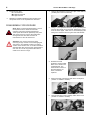
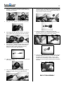
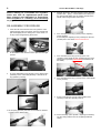
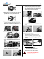
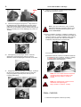
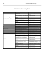
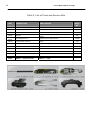
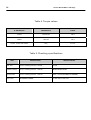
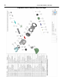
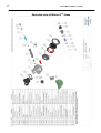
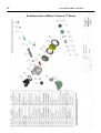
SERVICE MANUAL
MIKRON
SECOND STAGE
Copyright ©2006 Aqua Lung France
Ref : Service Manual - Mikron 2nd Stage Rev. 07/2008
2
Service Manual Mikron 2nd Stage
Index
COPYRIGHT............................................................................................................................... 3
INTRODUCTION........................................................................................................................ 3
WARNINGS, ATTENTION, NOTES..........................................……………............................... 3
MAINTENANCE.......................................................................................................................... 3
GENERAL INSTRUCTIONS...........................................................……..................................... 3
GENERAL CONVENTIONS............................................................…........................................ 3
DISASSEMBLY PROCEDURE..............................................................…..................................4
RE-ASSEMBLY PROCEDURE...............................................................….................................6
FINAL CHECKS.................……...............................................................…….............................9
Table 1. Troubleshooting guide................................................................…..............................10
Table 2. List of tools and service kits........................................................……….......................11
Tableau 3. Nettoyants et lubrifiants recommandés..................................................................... 12
Table 3. Recommended cleaners and lubricants.............................................….......................13
Table 4. Torque settings...........................................................................………....................... 14
Table 5. Checking specifications..............................................................……............................14
Maintenance notes ………………...........................................................…….............................15
Exploded view of Mikron Second Stage......................................................................................16
Revision
Rev. 07/08
Revision description
Modification of the torque of the following parts 127824, 127833 and 127846.
The new torque is equal to 0.5 N.m
F I R S T
T O
3
D I V E
COPYRIGHT
GENERAL INSTRUCTIONS
This manual is the property of Aqua Lung France. Any
copying, photocopying, reproduction, translation, electronic
distribution (email, Internet...), even partial, and in whatever
format, is expressly forbidden without the written consent of
Aqua Lung France.
1.
In order to carry out the procedures described in this
manual correctly it is important that you follow the steps
in the exact order indicated. Read the manual through
completely so that you become familiar with all the
procedures, the special tools and the replacement parts,
before starting to disassemble the product. Keep this
manual open near to you so that you can refer to it step
by step. Do not rely on your memory.
2.
All servicing and repair procedures should be carried
out in a workshop that is clean, well lit, easy to access
and specially fitted for the purpose.
3.
The regulator body should never be directly held in the
jaws of a vice. To hold the body, screw the tool 006230
into the HP port and then grip the tool with the vice.
4.
Once the regulator has been disassembled, the reusable components should be separated from the
components that need to be replaced. Fragile items with
seats or crowns with critical sealing surfaces should be
separated and protected during servicing in order to
prevent any damage.
5.
Use only spare parts from Aqua Lung service kits.
Never replace an Aqua Lung part with one from another
manufacturer, even if it appears similar.
6.
Never re-use regulator parts which should be replaced
on the pretext that the regulator has seen little use since
its manufacture or since its last service.
7.
When reassembling, check that the torque used
conforms with that shown in Table 4, Torque. Some
parts can be irretrievably damaged if the acceptable
torque is exceeded.
©2006 Aqua Lung France.
INTRODUCTION
This manual gives the instructions and the recommendations
for the disassembly, the cleaning, the checking, the
reassembly and the adjustment of an Aqua Lung regulator.
This manual is not an instruction manual for unqualified
personnel. The procedures described in this manual are
intended only for qualified personnel who have been trained
in the servicing of Aqua Lung equipment during a specialised
course.
If you do not understand certain procedures in this manual
you should contact an Aqua Lung service consultant before
undertaking any operation.
WARNINGS, ATTENTION, NOTES
Certain icons have been used to facilitate the reading and
understanding of this manual. They have the following
meanings :
.
WARNING: Indicates situations that could result in
serious or fatal accidents if the advice given is not
followed correctly.
.
ATTENTION: Indicates a situation or action that
could cause serious damage to the product,
making it dangerous if the advice given is not
followed correctly.
GENERAL CONVENTIONS
NOTE : Notes are used to emphasize
important points as well as information which
needs to be remembered.
1.
Unscrew: to unscrew a threaded part, turn it anticlockwise.
2.
Screw: to screw a threaded part, turn it clockwise.
3.
Remove the O-ring: To remove an O-ring follow the
method below, using the special tool provided for this
purpose. Any tool that could damage the O-ring should
be avoided. In every case, replace the O-ring removed
with a new one.
MAINTENANCE
ATTENTION: Whatever the number of dives
carried out during a year, the regulator should
receive a complete service each year. If the
regulator is used in a chlorinated or
aggressive environment the service period
should be reduced to six months.
In order to conform with the Aqua Lung Regulator
Lifetime Guarantee, all servicing (inspection, servicing
and repairs) should be recorded in the Service Record
incorporated in the regulator User Manual.
The conventions described below define the actions to be
carried out when an instruction is given.
Press simultaneously on the
two sides of the O-ring in
order to form an ‘eye’. .
Insert the special tool into this
eye to remove the O-ring.
4
Service Manual Mikron 2nd Stage
4.
The acronyms used:
LP: Low Pressure
MP: Medium Pressure
HP: High Pressure
5.
Numbers in brackets indicate the part number of the
component shown on the exploded view attached.
1.
Using a flat screwdriver, lift the two clips of the deflector
(127825) then remove it manually.
2.
Using 2 11/16 spanners hold the screw (127819) and
unscrew the swivel nut on the hose. Remove the O-ring
from the hose nipple. Take care to avoid damaging the
seal groove. Remove the O-ring from the hose threads.
DISASSEMBLY PROCEDURE
Note: Before commencing disassembly, consult
the exploded view to check the reference
numbers of all parts requiring replacement.
These parts should all be replaced by new parts
and should not be re-used on the pretext that
the regulator has seen little use since its
manufacture or since its last service.
Attention: Use only the special tool when
removing O-rings in order to avoid damaging the
seal recess. The slightest scratch on a sealing
surface could cause a leak. If a surface should be
damaged then this part should be replaced with a
new one. Do not use any pointed instrument or
metal tool to remove O-rings.
3. Pull back the hose
protectors and check that
there are no dents in the
crimped sleeve. The
hose should not move in
the metal sleeve. If it
does, it should be
replaced.
4.
Remove the clip (129154) and pull off the mouthpiece
(123697 or 123698 or 127826).
5.
Unscrew the outer crown (127843). Take off the cover
(127836 or 127838 or 127848).
F I R S T
T O
5
D I V E
6.
Using the tool (129198), unscrew the diaphragm nut
(127814 or 127832). Remove the washer (127815) and
the diaphragm (127816).
7.
Using the 11/16” spanner, unscrew the nut (127818).
8.
Push slightly the valve spindle (127817). Unscrew the
valve spindle screw (127819) from the valve spindle.
9.
Turn over the 2nd stage and recover the shuttle-valve
assembly (AP2036), spring (AP2021) and counterbalance chamber (127607). Remove the O-ring
(AP2041) and the valve seat (AP2034).
10. Take out the valve spindle (127817) manually, Recover
the O-ring (473056)
12. Unscrew the cam (127822) from the valve spindle screw
(127819). Using a 3mm Allen key, unscrew the adjusting
screw (127823) from the cam (127822). Remove the Orings (121130, 213716 and 124707).
13. Using a screwdriver (111399) unscrew the seat
(AP2033). Push the tool (116236) inside the insert and
push the seat out. Remove the O-ring (444243).
14. Left up the edge of the exhaust valve and check that the
surface is clean and free from any scratches. It should
be flexible and have a clean contour. If it is in good
condition it is not necessary to remove it and it can be
reused. If it shows any signs of deterioration it should be
removed.
11. Using a 3mm Allen key, unscrew the plug (127824 or
127833 or 127846). Remove the adjusting knob
(127821).
END OF DISASSEMBLY
6
Service Manual Mikron 2nd Stage
Before starting to re-assemble the regulator,
make sure that all replacement parts have
been cleaned and lubricated in accordance
with Procedure A : Cleaning and Lubricating
on page 13.
5.
Maintain the lever in the upper position. Fit the assembly
(shuttle valve – spring – counter balance chamber) into
the valve spindle taking care to position the tabs of the
shuttle valve facing the tabs on the lever.
6.
Fit a new lubricated O-ring (124707) on the adjusting
screw (127823).
Screw totally the adjusting screw (127823) into the cam
(127822) then come back one turn and 3/4 turn.
7.
Fit a new lubricated O-ring (213716) on the cam
(127822). Screw totally the cam (127822) into the valve
spindle screw (127819) until its stop (the thread must
be visible).
8.
Fit a new lubricated O-ring (121130) on the valve spindle
screw (127819).
9.
Screw of a single turn only the valve spindle screw
(127819) on the valve spindle (127817).
RE-ASSEMBLY PROCEDURE
1. If the exhaust valve has been removed, pass the valve
tail through the hole in the casing (from the outside) and
pull the tail lightly into the casing. If it is a new valve, cut
off any excess length leaving about 5mm.
2.
3.
Fit the deflector and check that the 2 clips are in the right
position.
Fit a new lubricated O-ring (AP2041) on the shuttle valve
(AP2036). Fit the valve seat (AP2034). Lubricate the Oring (AP2041) correctly.
4. Fit the spring (AP2021) then the counter balance chamber
(127607) on the shuttle valve.
10. Fit the assembly (valve spindle + adjusting mechanism)
into the casing until the lever is completely inside the
casing.
F I R S T
T O
7
D I V E
16. With the flat side of the casing at eye level, screw in the
adjusting knob until the lever is about 4mm below the
level of the casing edge. Now unscrew it until the lever
just shows above the edge of the casing. Press on the
lever and check that it returns to the high position (the
sign that the shuttle valve is well positioned).
11. Maintain the lever in the upper position. Push slightly the
assembly outside the casing, and screw the valve
spindle screw until its stop.
12. Line up the spins of the screw with the seating of the
casing by unscrewing the valve spindle screw. Looking
at the case as the pictures, the two upper spins and the
lever must be on both sides of a vertical plan.
17. Fit new lubricated O-rings on the hose nipple and on the
thread.
13. Re-fit completely the assembly into the casing.
18. Ajustement du Levier (129178).
Attach the adjusting connector (122041) on the
adjustment tool (122046). Connect a MP hose to the
tool and then fit the assembly to a Mikron 1st stage that
has its MP set to 9.5 bar. Put the regulator under
pressure.
14. Fit a new lubricated O-ring (124706) on the valve
spindle, then screw and tight the screw (127818) to 0.3
m.kg.
15. Fit a new lubricated O-ring (444243) on the
seat(AP2033). Fit the seat (threaded part first) into the
insert and push it fully home using a screwdriver.
Slide the tool (129001) across the top of the casing.
With the tool in MINI position:
nd
the 2 stage MUST NOT leak
the tool MUST NOT press on the lever
the tool MUST flush the lever
Screw the seat in or out to adjust the setting.
The tool (129001) in its MAXI position
MUST NOT BE USED TO ADJUST THE
MIKRON SECOND STAGE.
8
Service Manual Mikron 2nd Stage
MINI
19.
nd
Close the air supply and purge the 2 stage. Remove
the adjustment tool. Fit the diaphragm (127816). Press
well in all around its edges to ensure that it is correctly
positioned. Fit the washer (127815) and then using the lug
spanner (129198) screw in the diaphragm nut (127814 or
127832).
22.
Using a 11/16” spanner, maintain the nut (127818) and
then tight the hose nut to 0.3m.kg.
Note: if you have a test bench, carry out these
tests before fitting the mouthpiece and the knob
with its plug. Test instructions are given in the
section Final Checks.
23. Fit the mouthpiece (123697 or 123698 or 127826) on to
the casing. If it is a Comfobite mouthpiece check that the
support is at the top. Fit the mouthpiece collar (129154)
into the groove provided. The collar lever should be
underneath and positioned on the hose side.
24. Fit the adjusting knob (127821)
20.
After tightening the diaphragm washer, check the
diaphragm is well positioned by pulling on several
directions. Check the diaphragm is not stuck, if not refit it.
21.
Engage the front cover (127836 or 127838 or 127848) in
the ring cover (127843), and then screw it on the case.
Using a lug spanner (129198) screw the ring cover
(127843) until its stop.
25. Maintain the knob (127821) in the MAXI POSITION
and tighten the plug (127824 or 127833 or 127846)
to 0.5 N.m using a dynamometer screwdriver
(equipped with a 3mm Allen key).
NOTE: The Cam 127822 must be unscrewed
completely until its stop to be able to tight
correctly the Plug 127824 or 127833 or
127846.
NOTE: The adjusting knob 127821 must be
maintained when tightening the
Plugs (127824 or 127833 or 127846).
FINAL CHECKS
1. Pressurise the regulator to 200 bar (±10 bar)
F I R S T
T O
D I V E
Note: Tests 2,3 et 4 require the use of
a regulator test bench.
2. Check opening effort. Apply a gradual inhalation
effort. When the MP starts to fall, release the pressure
and compare the result with the limits shown in Table 5.
Checking Specifications. If the opening effort is
outside these limits consult Table 1. Troubleshooting
Guide.
If the adjusting screw 127823 is not correctly adjusted,
unscrew it until its stop and then screw it to one turn and
3/4 turn. You have the possibility to screw and unscrew
of +/- 1/2 turn from this position to get the suitable
cracking effort.
3. Check depression / flow. Apply an inhalation flow of
400 l/min and check that the depression does not
exceed 15 mbar. If it exceeds this value consult Table 1.
Troubleshooting Guide.
4. Check for leaks. Connect the first stage to a cylinder
charged to 200 bar, open the valve and submerge the
assembly in a bath of water for 1 minute. Check that
there are no leaks. If there are apparent leaks,
nd
disassemble the 2 stage completely and check all
sealing surfaces and the positioning of the parts.
END OF REASSEMBLY
9
10
Service Manual Mikron 2nd Stage
Table 1. Troubleshooting Guide
SYMPTOM
Leak or free flow at 2nd stage
Insufficient purge flow or work of
breathing too high
Water leak
POSSIBLE CAUSE
TREATMENT
1. MP too high
1. Refer to First stage Troubleshooting
Guide
2. The valve (AP2034) is worn or damaged.
2. Replace the valve
3. The seat (AP2033) is not correctly
adjusted
3. Readjust the seat
4. The lever (127828) is bent
4. Replace the lever
5. The sealing face of the seat (AP2033) is
damaged.
5. Replace the seat
6. The spring (AP2021) is damaged
6. Replace the spring
1. MP too low
1. Refer to First stage Troubleshooting
Guide
2. The adjusting screw 127823 is not
correctly adjusted
2.Readjust the adjusting screw
3. The valve (AP2033) is not correctly
adjusted, the lever adjustment is too low
3. Readjust the lever and the valve
4. MP hose obstructed
4. Clean or replace the hose
5. The lever (127828) is bent
5. Replace the lever
1. Hole in mouthpiece (123697)
1. Replace the mouthpiece
2. Diaphragm (129150) damaged
2. Replace the diaphragm
3. Exhalation valve (129174) damaged
3. Replace the valve
4. The cam O-ring (473057) is dirty, worn or
damaged
4. Replace the O-ring
5. 5. The diaphragm is not correctly fitted
between the casing and the washer
(127815)
5. Disassemble the purge button and
refit the assembly correctly
6. The casing is damaged.
6. Check the sealing face of the
exhalation valve. Replace the casing
7. The O-rings (127707 and/or 121130) are
damaged.
7. Replace the O-ring
8. The insert O-ring (124706) is damaged.
8. Replace the O-ring
Service Manual Mikron 2nd Stage
11
Table 2. List of Tools and Service Kits
DESCRIPTION
APPLICATION
US
PART
NO.
MP pressure gauge complete 0/16B
Checking medium pressure
111610
O-ring tool
Fitting and removing O-rings
944022
116236
Seat fitting tool
Seat assembly/disassembly
109436
129198
Ring tool
Tighten/loosen diaphragm washer and ring cover on
Mikron
Seat adjustment tool
Adjusting seat under pressure
122155
Torque wrench 0.5 m.kg
Plugs
129001
Lever adjustment tool
Adjust the height of the lever
N/C
Medium flat wrench
seat
N/a
N/C
Flat wrench 17mm (x2)
Hose nut
N/a
N/C
4mm Allen key
MP et HP plugs
N/a
N/C
3mm Allen key
Adjusting screw and plug
N/a
REF
116222
N/C
122046 +
122041
127863
nd
Mikron 2
stage Service Kit
Mikron 2nd stage
N/a
100190
N/a
129001
12
Service Manual Mikron 2nd Stage
Table 3. Recommended cleaners and lubricants
LUBRICANT / CLEANER
Christolube MCG 111
APPLICATION
All O-rings
SOURCE
Aqua Lung, ref. 480025
Attention: Silicone parts do not require lubrication. Do not grease them. Greasing silicone
parts can change their molecular construction and cause premature degradation of the material.
Oakite #31
Acid bath for cleaning brass and stainless
steel parts.
Oakite Products, Inc.
NETALU
Acid bath for cleaning brass and stainless
steel parts.
Aqua Lung, ref. 455001
Diluted white vinegar
Acid bath for cleaning brass and stainless
steel parts.
Household stores
Attention: Do not use hydrochloric acid for cleaning parts. Hydrochloric acid, even when well
diluted, attacks the coating of metal parts and leaves a corrosive deposit that damages plastic
parts and O-rings.
Washing-up liquid (diluted with hot water)
Degreases brass and stainless steel parts; Household stores
general cleaning of plastic and rubber
parts.
Disinfectant STERANIOS 2%
Disinfectant for all plastic and metal parts.
Aqua Lung ref : 382062
Service Manual Mikron 2nd Stage
13
Procedure A
Cleaning and Lubricating
(All Aqua Lung Regulators)
Cleaning brass and stainless steel parts.
1.
2.
3.
Pre-clean by soaking in NETALU diluted to 25%.
Cleaning in an ultra-sonic bath filled with a mixture of washing-up liquid + hot water. If some resistant deposits remain
then fill the ultrasonic bath with white vinegar and repeat. DO NOT put plastic, rubber, silicone or anodised aluminium
parts in contact with vinegar.
Rinse in demineralised or fresh water to avoid calcium deposits. Soak for 10 minutes. Dry with filtered low pressure air and
then check that their condition is now suitable for re-use.
Cleaning plastic, rubber and anodised aluminium parts.
For anodised aluminium parts : soak in a « NETALU diluted to 25% ». Rinse in fresh water and dry with low-pressure filtered air.
For plastic parts. (casings, plugs..) : clean in an ultrasonic bath containing a mixture of washing-up liquid and hot water. Use only a
toothbrush with nylon bristles to remove any deposits. Rinse in fresh water and dry with low-pressure filtered air
Attention: D not place plastic and rubber parts in contact with acid solutions. This could alter their physical
properties and cause degradation and premature breakdown.
Disinfecting parts .
For disinfection, leave plastic and metal parts to soak for 20 minutes in a bath of STERANIOS 2% ref. 382062 (ready to use).
Rinse the parts thoroughly after soaking. Toxic product, follow the instruction for its use.
Cleaning parts for Nitrox/O2 use.
1.
2.
3.
4.
Metal parts : Pre-clean by soaking in NETALU diluted to 25%.
Ultrasonic cleaning in Promoclean TP108 diluted at 5% .
Rinse in demineralised water. Soak for 10 min.
Dry in the open air in a clean and dust-free atmosphere. Place the parts on a white cloth, allow to dry and check after
drying that the cloth shows no grease deposits and that the condition of the parts is appropriate for re-use with Nitrox/O2.
Cleaning hoses.
If there is significant corrosion then it is permissible to soak only the ends in an ultrasonic bath, avoiding any possibility of the
solution entering the hose. Rinse in fresh water and allow to dry with the connections hanging down. Dry the inside with filtered
compressed air before reconnecting the hose to the regulator.
Wiping.
To wipe parts, use a white filter paper, a pure cotton cloth or any other material that does not produce fluff.
Inspection.
Visually check under a white light (day light or artificial light).
The parts are completely free of any traces of :
1.
2.
3.
4.
organic materials (oil, grease, paint, rust…)
cleaning agents
dust
humidity
Lubrication.
When handling O-rings wear unpowdered latex gloves. It is important not to allow contact between the internal components and the
skin or any other source of contamination when the regulator is being prepared for Nitrox use. All seals should be lubricated with
Christolube MCG111. Cover the seals with a light film of grease and remove any excess by rolling the seal between finger and
thumb. Do not use an excess of grease; this can have the effect of accumulating particles that could damage the O-rings.
14
Service Manual Mikron 2nd Stage
Table 4. Torque values
N° REFERENCE
DESCRIPTION
FORCE
127818
Insert screw
3 N.m
129861
Hose Nut
3 N.m
127824, 127833 and 127846
Plug
0.5 N.m
Table 5. Checking specifications
TEST
INSTRUCTIONS
SPECIFICATIONS
Leak Test
160 bar < Working pressure < 200 bar
No leak
Medium Pressure
160 bar < Working pressure < 200 bar
MP at 9.5 bar ± 0.5 bar
Opening effort
160 bar < Working pressure < 200 bar
Mikron : between 2.8 mbar and 3.8 mbar
Effort / Flow
MP at 9.5 bar ± 0.5 bar
15 mbar maxi at 400 L/min
15
Service Manual Mikron 2nd Stage
Maintenance Notes.
16
Service Manual Mikron 2nd Stage
Exploded view of Mikron Lady 2nd stage.
17
Service Manual Mikron 2nd Stage
Exploded view of Mikron 2nd Stage
18
Service Manual Mikron 2nd Stage
Exploded view of Mikron Octopus 2nd Stage
19
Service Manual Mikron 2nd Stage
1ere Avenue – 14e rue – BP 148
06513 CARROS cedex – France
00.33.(0)4.92.08.28.88
FAX 00.33.(0)4.92.08.28.99