1
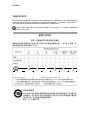
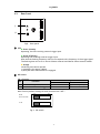
User's Manual LQ-200CL RGB Color & NIR 4CCD Line Scan Camera Document Version:1.3 LQ-200CL_Ver.1.3_March2011 LQ-200CL Notice The material contained in this manual consists of information that is proprietary to JAI Ltd., Japan and may only be used by the purchasers of the product. JAI Ltd., Japan makes no warranty for the use of its product and assumes no responsibility for any errors which may appear or for damages resulting from the use of the information contained herein. JAI Ltd., Japan reserves the right to make changes without notice. Company and product names mentioned in this manual are trademarks or registered trademarks of their respective owners. Warranty For information about the warranty, please contact your factory representative. Certifications CE compliance As defined by the Directive 2004/108/EC of the European Parliament and of the Council, EMC (Electromagnetic compatibility), JAI Ltd., Japan declares that LQ-200CL complies with the following provisions applying to its standards. EN 61000-6-3 (Generic emission standard part 1) EN 61000-6-2 (Generic immunity standard part 1) IEC61000-4-2(Electrostatic discharge immunity test) FCC This equipment has been tested and found to comply with the limits for a Class B digital device, pursuant to Part 15 of the FCC Rules. These limits are designed to provide reasonable protection against harmful interference in a residential installation. This equipment generates, uses and can radiate radio frequency energy and, if not installed and used in accordance with the instructions, may cause harmful interference to radio communications. However, there is no guarantee that interference will not occur in a particular installation. If this equipment does cause harmful interference to radio or television reception, which can be determined by turning the equipment off and on, the user is encouraged to try to correct the interference by one or more of the following measures: - Reorient or relocate the receiving antenna. - Increase the separation between the equipment and receiver. - Connect the equipment into an outlet on a circuit different from that to which the receiver is connected. - Consult the dealer or an experienced radio/TV technician for help. Warning Changes or modifications to this unit not expressly approved by the party responsible for FCC compliance could void the user’s authority to operate the equipment. 2 LQ-200CL Supplement The following statement is related to the regulation on “ Measures for the Administration of the control of Pollution by Electronic Information Products “ , known as “ China RoHS “. The table shows contained Hazardous Substances in this camera. mark shows that the environment-friendly use period of contained Hazardous Substances is 15 years. 嶷勣廣吭並㍻ 嗤蕎嗤墾麗嵎賜圷殆兆各式根楚燕 功象嶄鯖繁酎慌才忽佚連恢匍何〆窮徨佚連恢瞳麟半陣崙砿尖一隈〇云恢瞳ゞ 嗤蕎嗤 墾麗嵎賜圷殆兆各式根楚燕 〃泌和 ・・・・・ ・・・・・ ・・・・・ ・・・・・ ・・・・・ ・・・・・ ・・・・・ 桟隠聞喘豚㍉ 窮徨佚連恢瞳嶄根嗤議嗤蕎嗤墾麗嵎賜圷殆壓屎械聞喘議訳周和音氏窟伏翌 亶賜融延、窮徨佚連恢瞳喘薩聞喘乎窮徨佚連恢瞳音氏斤桟廠夛撹冢嶷麟半 賜斤児繁附、夏恢夛撹冢嶷鱒墾議豚㍉。 方忖仝15々葎豚㍉15定。 LQ-200CL - Table of contents – 1. 2. 3. 4. General ....................................................................................................... 5 Camera nomenclature ...................................................................................... 5 Main features ................................................................................................ 5 Locations and functions .................................................................................... 6 4.1. Locations and functions ............................................................................... 6 4.2. Rear Panel .............................................................................................. 7 5. Connectors and pin assignment ........................................................................... 8 5.1. 12-Pin Connector (Hirose) ............................................................................ 8 5.2. Digital Output / Interface Connectors for CameraLinkTM ........................................ 8 5.3. Input and output circuits ............................................................................. 9 5.3.1 Trigger input........................................................................................ 9 5.3.2 EEN / XEEN output (Exposure ENable) ........................................................9 5.3.3 Camera Link Interface (Bit allocation) ....................................................... 10 5.3.4 Camera link output port ........................................................................ 11 5.3.5 Bit allocation of the output video............................................................. 11 6. Functions and Operation ................................................................................. 12 6.1. Basic functions ....................................................................................... 12 6.2. Operating mode ...................................................................................... 13 6.2.1 No-Shutter mode with internal trigger ....................................................... 14 6.2.2 No-Shutter mode with external trigger ...................................................... 15 6.2.3 Shutter-Select mode with internal trigger................................................... 16 6.2.4 Shutter-Select mode with external trigger .................................................. 17 6.2.5 Pulse Width Control (PWC) mode ............................................................. 18 6.3. Scan rate and exposure time range ............................................................... 19 6.3.1 Minimum cycle time of external trigger ..................................................... 19 6.3.2 Minimum trigger pulse width. ................................................................. 19 6.3.3 Compatibility of trigger modes and functions............................................... 19 6.3.4 Trigger modes and auto white balance modes matrix table .............................. 19 7. Functions listed alphabetically by command acronyms ............................................. 20 7.1 Command AHRS – Request Status After One-Push AWB........................................ 20 7.2 Command AL – Automatic Line Rate Reference Level ......................................... 20 7.3 Command AR – Automatic Line Rate Setting .................................................... 20 7.4 Command ARST – Auto Reset Mode ............................................................... 20 7.5 Command AH - Activate One-Push Auto White Balance (AWB) - Shutter ................... 21 7.6 Command AW – Activate One-Push Auto White Balance (AWB) - Gain ...................... 21 7.7 Command BA – Bit Allocation ...................................................................... 21 7.8 Command BI – Binning (horizontal only) ......................................................... 22 7.9 Command BL – Master Black Level ................................................................ 22 7.10 Commands BLR , BLB and BLIR – Black Level Red, Blue and NIR ............................. 22 7.11 Command BLM - Black Level Mode .............................................................. 22 7.12 Command EI – Interlocked R, G, B & NIR Exposure............................................. 23 7.13 Command GA – Master Gain Level ................................................................ 23 7.14 Commands GAR, GAB and GAIR – Gain Level Red, Blue and NIR. ............................ 23 7.15 Commands GAR2 , GAG2, GAB2 and GAIR2 – Fine Gain (R,G, B and NIR)................... 24 7.16 Command GM - Gain Mode ..................................................................... 24 7.17 Command LR - Line Rate (Scan Rate) ............................................................ 24 7.18 Command LUTC - LUT Control ................................................................. 24 7.19. Command NR - Noise Reduction ............................................................ 25 7.20 Command PBC – Enable Pixel Black (FPN) Correction ......................................... 25 7.21. Command PBR – Run Pixel Black Correction and Store to User Area ........................ 25 7.22. Command PBS - Request Status After Pixel Black Correction ............................. 26 7.23. Command PER,PEG,PEB and PEIR – Programmable Exposure for R,G,B,and NIR .......... 26 7.24. Command PGC – Enable Flat-Field Correction (pixel gain) .................................... 27 7.25. Command PGR – Run Flat-Field Correction and Store in User Area .......................... 27 7.26. Command PGS - Request Status After Pixel Gain Correction ............................. 28 3 LQ-200CL 7.27. Command SDC – Select Shading Correction Mode ............................................... 7.28. Command SDR – Run Shading Correction........................................................ 7.29. Command SDS – Request Status After Executing Shading Correction Command ......... 7.30. Command TG – Trigger Origin .................................................................... 7.31. Command TI – Trigger Input ...................................................................... 7.32. Command TP – Trigger Polarity .................................................................. 7.33. Command TR – Trigger Mode ..................................................................... 7.34. Command TS – Test Pattern ...................................................................... 7.35. Command WB – White Balance ................................................................... 8. Serial communication and command list .............................................................. 8.1. Serial communication ............................................................................... 8.2. Command list ......................................................................................... 9. Camera Control Tool for LQ-200CL ..................................................................... 10. External appearance and Dimensions ................................................................ 11. Specifications ........................................................................................... 11.1 Typical data ............................................................................................. 11.2 Camera Spectral sensitivity ........................................................................ Appendix .......................................................................................................... 1. Precautions .............................................................................................. 2. Typical Sensor Characteristics ....................................................................... 3. Caution when mounting a lens on the camera..................................................... 4. Caution when mounting the camera ................................................................ 5. Exportation .............................................................................................. 6. References .............................................................................................. Change history ................................................................................................... User's Record ..................................................................................................... 4 28 28 29 30 30 30 30 31 32 33 33 34 39 43 44 44 46 47 47 47 47 48 48 48 49 50 LQ-200CL 1. General The LQ-200CL is a 4CCD line scan camera using four 2048 pixel line sensors mounted on a prism, for the R, G,B and NIR channels. It operates with a 40 MHz pixel clock, resulting in a maximum line rate of 19,048 lines per second. The camera outputs digital data in 4 x 8 bits or 4 x 10 bits format via Camera Link. The camera is configured by software through the serial communication port of the Camera Link interface, or via RS-232C through a 12-pin Hirose connector. The camera accepts M52 mount or F-mount lens. The LQ-200CL is a suitable camera for various applications such as inspection of fruits, vegetables ,circuits boards or electronic/mechanical parts, as the NIR image can catch scratches or blemishes on object surfaces which the RGB color image cannot find. The latest version of the operation manual can be downloaded from www.jai.com . The latest camera control tool for the LQ-200CL can be downloaded from www.jai.com . For camera revision history, please contact your local JAI distributor 2. Camera nomenclature The standard camera composition consists of the camera main body and sensor protection cap. The camera is available in the following versions: LQ-200CL Where L stands for "Line sensor, Q stands for "Quad CCD", 200 represents the resolution "2000 pixels", and CL stands for "CameraLinkTM" interface. 3. Main features 4CCD line scan camera with 2048 pixel resolution Dichroic beam splitter prism to separate R,G,B and NIR wavelengths 19,048 lines per second scan rate 40 MHz pixel clock 4 x 8 bits or 4 x 10 bits output through Camera Link interface Flat-field correction. Two point pixel-by-pixel compensation on each R,G,B and NIR channels Master gain control in the range of -3dB to +12dB with a fine gain control Flat Shading correction and Color Shading Compensation One-push auto white balance Binning function to increase sensitivity Gamma correction using LUT(Look Up Table) Auto reset function Noise reduction function Test pattern generator( color bar, gray, white ) for set-up and trouble shooting Electronic shutter (for selected modes) Short ASCII commands set-up via RS 232C or Camera Link M52 mount or F mount selectable Setup by Windows XP software About M52 mount: LQ-200CL employs a new M52 mount as the standard. This mount is recommended in the lens guide line for machine vision applications which is set by Japan Industrial Imaging Association in corporation with AIA and EMVA. The title of the guideline is “JIIA LER 004-2010 Recommended Mechanical Interfaces Applied for Each Image Size Classification” and issued on March 10th, 2010. 5 LQ-200CL 4. Locations and functions 4.1. Locations and functions Fig. 1 Location of external features 1 2 3 4 5 6 7 8 Lens mount Camera Link part 1 Camera Link part2 12-pin Hirose connector DIP switch Button LED indicator Camera mounting holes *1) Note: *2) Note: *3) Note: M52 mount (*1)Note) base connector (1) (*2)Note) medium connector (2) (*2)Note) DC +12, External trigger and RS-232C SW-1 ( refer to chapter 4.2 for the details) For one-push auto white balance Power, trigger input and operation indications 8 x M3, depth 5.5mm ± 0.2mm (*3) Note) Rear protrusion on M52 mount lens must be less than 13mm. When a CameraLinkTM cable is connected to the camera, please do not excessively tighten screws by using a driver. The CameraLink receptacle on the camera might be damaged. For security, the strength to tighten screws is less than 0.291 Newton meter (Nm). Tightening by hand is sufficient in order to achieve this. The depth of mounting hole is 5.5mm ± 0.2mm. If the longer screws than 5.7mm are used, they may damage the circuit board inside. 6 LQ-200CL Rear Panel D IGITAL I / O - 1 4.2. ① POW ER / TRIG D C IN /TRIG ② SW1 D IGITA L I / O - 2 W .B . Fig2. Rear panel ① LED Green (Steady) Operating, but not receiving external trigger input Green (Flashing) Operating and receiving external trigger input. Note that the flashing frequency does not correspond to the frequency of the trigger signal. The flashing does not occur in the No-Shutter internal and Shutter-Select internal modes. Orange Initializing and cannot operate 1) Initializing for approx. 800ms 2) One-push auto white balance is engaged. ② DIP switch SW-1 function No 1 2 Settings Function ON Hirose 12Pin 75Ω Serial communication Termination of External trigger Note: Factory default settings for both functions are “OFF”. OFF ON Serial Communication 75 Ω Fig.3 DIP switch 7 OFF Camera link (CC1) TTL LQ-200CL 5. Connectors and pin assignment 5.1. 12-Pin Connector (Hirose) Type: HR10A-10R-12PB-01 Hirose (Male) Use the part number HR10A-10P-12S for the cable side Fig. 4 5.2. Pin No. Signal 1 2 3 4 5 6 7 8 9 10 11 12 GND +12V DC in GND Reserved GND RxD in TxD out GND XEEN out Trigger in +12V DC in GND Remarks Do not connect RS-232C RS-232C TI=1, or set TI=0 for input via CL 12-pin Hirose connector Digital Output / Interface Connectors for CameraLinkTM Type: 26P MRD Connector 3M 10226-1A10JL Fig. 5 Camera Link connector This camera can be used with all Camera Link products that comply with the AIA Camera Link standard. Cables, transmission systems and frame grabbers/acquisition boards that do not comply with the Camera Link standard may work with this camera, but JAI Camera Solutions cannot be held responsible for loss in performance or damage of equipment, including the camera. Connector 1 (32Bit, 40 Bit) Pin No In/Out 1,14 2(-),15(+) 3(-),16(+) 4(-),17(+) 5(-),18(+) 6(-),19(+) 7(+),20(-) 8(-),21(+) 9(-),22(+) 10(+),23(-) 11,24 12,25 13,26 O O O O O I O I I Name Note Shield TxOUT0 TxOUT1 TxOUT2 TxClk TxOUT3 SerTC (RxD) SerTFG (TxD) CC1 (Trigger) CC2(Reserved) N.C N.C Shield GND 8 Data out Clock for CL Data out LVDS Serial Control Trigger GND LQ-200CL Connector 2 ( Used only for 4 x 10 Bit output) Pin No In/Out Name 1,14 2(-),15(+) 3(-),16(+) 4(-),17(+) 5(-),18(+) 6(-),19(+) 7(+),20(-) 8(-),21(+) 9(-),22(+) 10(+),23(-) 11,24 12,25 13,26 5.3. O O O O O Shield TxOUT0 TxOUT1 TxOUT2 TxClk TxOUT3 N.C N.C N.C N.C N.C N.C Shield Note GND Data out Clock for CL Data out GND Input and output circuits 5.3.1 Trigger input The External Trigger signal can be applied either through the Camera Link connector or at pin 10 of the 12-pin Hirose connector. The command to change this setting is TI (Trigger Input). TI=0 for Camera Link connector (factory default) and TI=1 for 12-pin Hirose connector. The input via the 12-pin Hirose connector is AC coupled. To allow long pulses, which may be required when using the Pulse Width Control (PWC) trigger mode, the input circuit is designed as a flip-flop circuit. The leading and trailing edges Fig. 6 Trigger input (12-pin Hirose) of the trigger pulse activate the circuit. The trigger input polarity can be changed by the command TP. At the 12-pin Hirose connector the External Trigger input is 4V ± 2V (TTL). It can be changed to 75 ohm termination by a DIP switch setting (SW 1). 5.3.2 EEN / XEEN output (Exposure ENable) This output corresponds to the exposure (accumulation) time of the camera. It works together with all operation modes. It is, however, not active when the test pattern function is enabled. The EEN signal is available at the Camera Link connector and at the 12-pin Hirose connector at the same time. At the Camera Link connector this signal has positive logic. At pin 9 of the 12-pin Hirose connector the signal has negative logic, and is therefore named XEEN. The output circuit is a 75 ohm complementary emitter follower. The circuit is powered from the 5V supply, resulting in an output level of more than 4V. It is not terminated. Fig. 7 9 XEEN Circuit (12-pin Hirose) LQ-200CL 5.3.3 Camera Link Interface (Bit allocation) The LQ-200CL follows the Camera Link standard in all respects. Port/Signal 8bitx4 output 10bitx4 output Connector Pin Name Port A0 Port A1 Port A2 Port A3 Port A4 Port A5 Port A6 Port A7 Port B0 Port B1 Port B2 Port B3 Port B4 Port B5 Port B6 Port B7 Port C0 Port C1 Port C2 Port C3 Port C4 Port C5 Port C6 Port C7 Port D0 Port D1 Port D2 Port D3 Port D4 Port D5 Port D6 Port D7 Out1_D0 Out1_D1 Out1_D2 Out1_D3 Out1_D4 Out1_D5 Out1_D6 Out1_D7 Out2_D0 Out2_D1 Out2_D2 Out2_D3 Out2_D4 Out2_D5 Out2_D6 Out2_D7 Out3_D0 Out3_D1 Out3_D2 Out3_D3 Out3_D4 Out3_D5 Out3_D6 Out3_D7 Out4_D0 Out4_D1 Out4_D2 Out4_D3 Out4_D4 Out4_D5 Out4_D6 Out4_D7 Out1_D0 Out1_D1 Out1_D2 Out1_D3 Out1_D4 Out1_D5 Out1_D6 Out1_D7 Out1_D8 Out1_D9 × × Out2_D8 Out2_D9 × × Out2_D0 Out2_D1 Out2_D2 Out2_D3 Out2_D4 Out2_D5 Out2_D6 Out2_D7 Out4_D0 Out4_D1 Out4_D2 Out4_D3 Out4_D4 Out4_D5 Out4_D6 Out4_D7 Port E0 Port E1 Port E2 Port E3 Port E4 Port E5 Port E6 Port E7 Port F0 Port F1 Port F2 Port F3 Port F4 Port F5 Port F6 Port F7 LVAL 1 × × × × × × × × × × × × × × × × Out3_D0 Out3_D1 Out3_D2 Out3_D3 Out3_D4 Out3_D5 Out3_D6 Out3_D7 Out3_D8 Out3_D9 × × Out4_D8 Out4_D9 × × 10 1 1 1 1 1 1 1 1 1 1 1 1 1 1 1 1 1 1 1 1 1 1 1 1 2 2 2 2 2 2 2 2 2 2 2 2 2 2 2 2 2 2 2 2 2 2 2 2 1 Tx0 Tx1 Tx2 Tx3 Tx4 Tx6 Tx27 Tx5 Tx7 Tx8 Tx9 Tx12 Tx13 Tx14 Tx10 Tx11 Tx15 Tx18 Tx19 Tx20 Tx21 Tx22 Tx16 Tx17 Tx0 Tx1 Tx2 Tx3 Tx4 Tx6 Tx27 Tx5 Tx7 Tx8 Tx9 Tx12 Tx13 Tx14 Tx10 Tx11 Tx15 Tx18 Tx19 Tx20 Tx21 Tx22 Tx16 Tx17 Tx24 LQ-200CL FVAL 1 LVAL 2 FVAL 2 DVAL EEN 1 2 2 1 1 Tx25 Tx24 Tx25 Tx26 Tx23 5.3.4 Camera link output port LQ-200CL handles R,G,B and NIR channels. The output ports for 8-bit and 10-bit are different. 8 bit output Input signal Camera link output RED Out1 GREEN Out2 BLUE Out3 Near IR Out4 Camera Link 1 Port a – c Camera Link 2 Port d – f Out5 Out6 10 bit output Input signal Camera link output RED Out1 GREEN Out2 BLUE Out3 Near IR Out4 Camera Link 1 Port a – c Camera Link 2 Port d – f Out5 Out6 Bit allocation of the output video Black 200mV 230mV Digital 10Bit (LSB) 32 890 1023 8-bit /10-bit 2000 255/1023 1740 222/ 890 Di gi tal _out ( mV) CCD out Digital 8Bit (LSB) 8 222 255 Anal og ( mV) 5.3.5 32 0 200 230 CCD_out( mV) Fig.8 11 Video output 8/32 0 LQ-200CL 6. 6.1. Functions and Operation Basic functions 300 400 500 600 700 700 800 800 900 900 300 400 400 500 500 600 600 700 700 800 800 900 900 Auto black, DSNU, PRNU, Shading, Fine Gain, Line Matrix, Knee, Noise reduction, User black 1000 Color Separation 300 AMP ADC 1000 AMP ADC Auto black, DSNU, PRNU, Shading, Fine Gain, Line Matrix, Knee, Noise reduction, User black AMP ADC Auto black, DSNU, PRNU, Shading, Fine Gain, Line Matrix, Knee, Noise reduction, User black MUX / Camera link IF 300 600 Digital Binning Dichroic Prism 500 Auto black, DSNU, PRNU, Shading, Fine Gain, Line Matrix, Knee, Noise reduction, User black MPX Light 400 AMP ADC OUT PUT 1000 1000 Fig.9 Signals flow The LQ-200CL uses four high-performance CCD line scan image sensors mounted on a prism block. During exposure, the incoming light is converted to electrons (electric charge) in the photodiodes (active pixels). The transfer gate controls the transfer of charge from photodiodes to the shift register. Activating the transfer gate terminates the exposure cycle, transfers the charge to the Horizontal Shift Register (2-phase buried channel CCD shift register) and starts a new exposure cycle. The line is subsequently read out in a single sequence starting with pixel 1. The exposure time is normally the same as the cycle time (in No-Shutter mode). By using the Exposure Control Gate (in Shutter-Select or Pulse Width Control trigger modes) the exposure time can be individually set to be shorter than the cycle time (the inverse of line rate). This also allows a fixed exposure time, independent of the line rate. In the LQ-200CL the exposure time can be set individually for all four channels. ・・ ・ ・ ・ ・ ・ ・ ・ ・・・・・・・・ AP2044 AP2045 AP2046 AP2047 TP2 TP3 Fake_OB10 Fake_OB11 Fake_OB12 Fake_OB13 Fake_OB14 Fake_OB15 Fake_OB16 Fake_OB17 Fake_OB18 Fake_OB19 OB0 OB1 OB2 OB3 OB4 OB5 OB6 OB7 OB8 OB9 TP0 TP1 AP0 AP1 AP2 AP3 Anti bloomi ng/Exposure Control Gate Output I s o0 I s o1 I s o2 Transfer Gate 2-Phase Buried Channel CCD Shift Register 10 3 2 2048 2075 OB TP AP I so : : : : Opt i cal Bl ack Pi xel s Tr ans i t i on Pi xel s Act i ve Pi xel s I s ol at i on St ages Fig.10 Sensor layout 12 2 10 LQ-200CL 6.2. Operating mode The LQ-200CL has three operating modes. They are No-Shutter mode, Shutter-Select mode and PWC (Pulse Width Control) mode. The following chapters explain the details of these three modes. The output detail is shown below and is common with all modes. LVAL DVAL 有効画素期間 2048 2 ・・・・・・・・・ 1ライン DM : OB : TP : AP : I so : ・・・・・・・・ 2 10 3 2100 1CLK=25ns Dummy Pi xel s Opti cal Bl ack Pi xel s Transi ti on Pi xel s Acti ve Pi xel s I sol ati on Stages LVAL : Li ne Val i d DVAL : Data Val i d Fig.11 Video output timing 13 DM22 DM23 DM24 10 AP2044 AP2045 AP2046 AP2047 TP2 TP3 Fake_OB10 Fake_OB11 Fake_OB12 Fake_OB13 Fake_OB14 Fake_OB15 Fake_OB16 Fake_OB17 Fake_OB18 Fake_OB19 3 DM19 DM20 DM21 I so0 I so1 I so2 OB0 OB1 OB2 OB3 OB4 OB5 OB6 OB7 OB8 OB9 TP0 TP1 AP0 AP1 AP2 AP3 Data DM0 DM1 DM2 22 LQ-200CL 6.2.1 No-Shutter mode with internal trigger In this mode the camera does not accept an external trigger signal, as the line rate is generated from an internal clock (user programmable, command LR). The exposure time is directly proportional to the line rate (Texp = 1/line rate). This mode is used when there is no external trigger signal available, and the speed of the object is fixed or can be pre-determined. The line rate can be varied from 1 line period (L) to 1024L in 1 clock (25ns) steps (19 kHz down to 18 Hz). When using this mode, a special function called “One-push auto line rate” is available. This mode automatically maintains a constant output level by changing the line rate. The line rate is automatically adjusted in order to maintain sensitivity without reducing the S/N ratio. To use this mode: Set function Trigger mode, No-Shutter Trigger origin, internal Line rate TR=0 TG=0 LR=2100 to 2150400 (52.5 µs to 53.8 ms in 25ns increments) Optional functions when using this mode: One-push auto line rate Auto line rate reference One-push white balance AR=0 AL=0 to 1023 WB Line rate 1L to 1024L LVAL EEN φPG φTG φAB φH1 φH2 DVAL Effective Video 14 O B 1 7 O B 1 8 O B 1 5 O B 1 6 O B 1 3 O B 1 4 O B 1 9 D M 2 D M 1 D M 0 A P 2 0 4 7 A P 2 0 4 6 O B 1 1 O B 1 2 A P 2 0 4 5 A P 2 0 4 4 O B 1 0 A P 2 0 4 3 Important Note Only gain-based one-push white balance function (WB) is available with this mode. T P 2 A P 2 0 4 2 Fig.12 No-Shutter mode with internal line rate generator T P 3 A P 2 0 4 1 A P 2 0 4 0 A P 2 0 3 9 A P 9 A P 2 0 3 8 A P 2 0 3 7 A P 8 A P 2 0 3 6 A P 6 A P 7 A P 1 1 A P 1 2 A P 4 A P 5 A P 1 0 A P 2 A P 3 A P 1 A P 0 O B 7 O B 8 O B 5 O B 6 O B 9 T P 0 T P 1 O B 3 O B 4 O B 1 O B 2 O B 0 I s o 2 I s o 1 I s o 0 D M 2 D M 0 D M 1 D M 2 1 D M 1 9 D M 2 0 D M 2 1 O B 1 8 O B 1 6 O B 1 7 O B 1 9 D M 1 9 D M 2 0 D M 2 O B 1 5 D M 0 D M 1 A P 2 0 4 7 O B 1 3 O B 1 4 A P 2 0 4 6 O B 1 1 O B 1 2 A P 2 0 4 5 A P 2 0 4 4 O B 1 0 T P 3 A P 2 0 4 3 A P 2 0 4 2 T P 2 A P 2 0 4 1 A P 2 0 4 0 A P 2 0 3 9 A P 2 0 3 8 A P 2 0 3 7 A P 2 0 3 6 A P 8 A P 9 A P 7 A P 1 1 A P 1 2 A P 1 0 A P 5 A P 6 A P 3 A P 4 A P 2 A P 0 O B 8 O B 6 O B 7 O B 5 O B 9 T P 0 T P 1 O B 3 O B 4 O B 1 O B 2 O B 0 I s o 2 I s o 0 I s o 1 D M 2 D M 0 D M 1 D M 2 0 D M 2 1 D M 1 9 A P 1 2048 Data LQ-200CL 6.2.2 No-Shutter mode with external trigger In this mode, the exposure time is directly proportional to the line rate. The line rate is generated externally by a trigger signal. This mode is used when an external trigger signal available, e.g. from an encoder, and the scan rate can be controlled by this signal. The camera can accept an external trigger through the Camera Link connector or though the 12-pin Hirose connector. To use this mode: Set function Trigger mode, No-Shutter TR=0 Trigger origin, external TG=1 Trigger input TI=0 or 1 Important note: When the one-push white balance has been initiated and the rear panel LED shows orange, the camera must receive continuous external trigger pulses corresponding to the frequency and duty cycle used in the application. Only gain-based one-push white balance function (WB) is available with this mode The minimum trigger interval is 52.6μs. TRI GGER LVAL 20 EEN 20(34) φPG φTG φAB φH1 φH2 DVAL 15 OB19 OB18 OB17 OB16 OB15 OB14 OB13 AP2046 AP2047 OB12 OB11 AP2044 AP2045 AP2042 AP2043 OB10 TP3 TP2 AP2040 AP2041 AP2038 AP2039 AP9 AP2037 AP8 AP7 AP2036 AP6 AP5 AP12 AP11 AP4 AP10 AP3 AP2 AP0 AP1 OB9 OB8 OB7 OB6 OB5 Fig. 13 No-Shutter mode with external trigger TP1 TP0 OB4 OB3 OB2 OB1 OB0 I s o2 I s o0 I s o1 DM2 DM0 DM1 DM20 DM21 DM19 OB18 OB17 OB19 OB16 OB15 OB14 OB13 AP2046 AP2047 OB12 OB11 AP2044 AP2045 OB10 AP2042 AP2043 TP2 TP3 AP2040 AP2041 AP2039 AP9 AP2037 AP2038 AP8 AP7 AP2036 AP6 AP12 AP11 AP5 AP4 AP10 AP3 AP2 AP1 AP0 OB7 OB6 OB5 OB9 OB8 TP1 TP0 OB2 OB1 OB0 OB4 OB3 I s o0 I s o2 I s o1 DM21 DM19 Data DM20 Effective video 2048 LQ-200CL 6.2.3 Shutter-Select mode with internal trigger This mode allows the user to have full control of the line rate and the exposure time individually, by programming separate timing generators. Subsequently, the camera does not accept an external trigger signal in this mode. To use this mode: Set function Trigger mode, Shutter-Select Line rate Trigger origin, internal Individual R, G and B exposure TR=1 LR=52.6μs to 53.683ms TG=0 EI=0(individual) EI=1(tracking with G) PER/PEG/PEB/PEIR=2 to 2150400 (in 25ns steps) Programmable exposure Important note: If using individual exposure, the EEN signal represents the channel with the longest exposure time The longest shutter operation is the same as the set trigger interval. If one-push auto white balance is used, using the shutter (command AH) or using the gain (command AW) depends on applications. If the auto white balance switch located on the rear panel is used, only the gain is effective. LVAL EEN φ PG φ TG φ AB_Rch T1 (Rch) φ AB_Gch 30ck T1 (Gch) φ AB_Bch 30ck T1 (Bch) 30ck Minimum 2ck φ H1 φ H2 DVAL Effective Video OB1 OB0 Iso2 Iso1 Iso0 DM1 DM2 DM21 DM0 DM20 DM19 AP2045 AP2046 AP2044 AP2047 TP3 TP2 AP2042 AP2043 AP2041 AP2039 AP2040 AP2037 AP2038 AP9 AP2036 AP8 AP12 AP7 AP6 AP11 AP4 AP5 AP10 AP3 AP2 AP1 AP0 OB9 OB8 OB7 OB6 OB5 TP1 TP0 OB4 OB3 OB2 OB1 OB0 Iso2 Iso1 Iso0 DM2 DM1 DM21 DM0 DM19 DM20 AP2046 AP2045 AP2047 TP3 AP2043 AP2044 TP2 AP2041 AP2042 AP2040 AP2038 AP2039 AP2037 AP9 AP8 AP2036 AP7 AP12 AP6 AP5 AP11 AP10 AP4 AP3 AP2 AP1 AP0 OB9 OB8 OB7 OB6 TP1 OB5 Fig. 14 TP0 OB4 OB3 OB2 OB1 OB0 Iso2 Iso1 DM2 DM1 DM21 DM20 DM0 DM19 Iso0 2048 Dat a Shutter-Select mode with internal line rate generator (and individual exposure) 16 LQ-200CL 6.2.4 Shutter-Select mode with external trigger This mode allows the user to have full control of the exposure time, by programming a timing generator, while the line rate is controlled by an external trigger signal. The camera can accept an external trigger through the Camera Link connector or though the 12-pin Hirose connector. To use this mode: Set function Trigger Trigger origin, external Individual R, G and B exposure TR=1 TG=1 EI=0(individual) EI=1(tracking with G) PER/PEG/PEB/PEIR=2 to 2150400 (in 25ns Programmable exposure steps) Important note: If using individual exposure, the EEN signal represents the channel with the longest exposure time The trigger interval is more than 52.6μs. If one-push auto white balance is used, using the shutter (command AH) or using the gain (Command AW) depends on applications. If the auto white balance switch located on the rear panel is used, only the gain is effective. When the one-push white balance has been initiated and the rear panel LED shows orange, the camera must receive continuous external trigger pulses corresponding to the frequency and duty cycle used in the application. The maximum trigger period is the interval of the input trigger. TRI GGER LVAL EEN φ PG φ TG 30ck以内 T1 (Rch) φ AB_Rch 30ck T1 (Gch) φ AB_Gch 30ck T1 (Bch) φ AB_Bch 30ck φ H1 φ H2 DVAL AP2046 AP2045 AP2043 AP2044 AP2047 TP3 TP2 AP2042 AP2041 AP2039 AP2040 AP2038 AP2037 AP9 AP2036 AP8 AP12 AP7 AP6 AP11 AP10 AP5 AP4 AP3 AP2 AP1 AP0 OB9 OB8 OB6 OB7 TP1 TP0 OB5 OB4 OB3 OB2 OB1 OB0 Iso2 Iso1 DM2 DM21 DM1 DM0 DM19 DM20 Dat a Iso0 Effectice Video 2048 Fig. 15 Shutter-Select mode with external trigger (and individual exposure) 17 LQ-200CL 6.2.5 Pulse Width Control (PWC) mode In this mode, the user has full control of both the line rate and the exposure time of each line via the External Trigger input. At the falling edge of the External Trigger signal, the exposure is initiated, and at the rising edge the exposure is terminated and read out. The camera can accept an external trigger through the Camera Link connector or though the 12-pin Hirose connector. To use this mode: Set function Trigger mode, PWC TR=2 Important Note: Possible pulse width: TTL input via 12P 52.6μs Camera link input 52.6μs One-push white balance by gain setting only. The trigger interval is more than (Exposure period + 52.6μs). When the one-push white balance has been initiated and the rear panel LED shows orange, the camera must receive continuous external trigger pulses corresponding to the frequency and duty cycle used in the application. TRIGGER LVAL EEN 10ck以内 φPG φTG 30ck以内 30ck φAB φH1 φH2 DVAL 18 A P 2 0 4 6 A P 2 0 4 5 A P 2 0 4 4 A P 2 0 4 3 A P 2 0 4 2 A P 2 0 4 1 A P 2 0 4 7 T P 3 T P 2 A P 2 0 4 0 A P 2 0 3 9 A P 2 0 3 8 A P 8 A P 9 A P 2 0 3 7 A P 2 0 3 6 A P 7 A P 1 2 A P 5 A P 6 A P 1 0 A P 3 A P 4 A P 1 A P 1 1 O B 8 O B 6 O B 7 O B 4 O B 5 O B 9 T P 1 T P 0 O B 2 O B 3 O B 0 O B 1 I s o 1 I s o 2 I s o 0 D M 1 D M 2 D M 2 0 D M 2 1 D M 0 Fig. 16 Pulse Width Control mode D M 1 9 A P 0 Data A P 2 Effective Video 2048 LQ-200CL 6.3. Scan rate and exposure time range 6.3.1 Minimum cycle time of external trigger Mode Minimum trigger cycle No-Shutter C1+52.5μs Shutter-Select C1+52.5μs PWC Exposure + C2 C1 =0.1μs; C2= 52.6μs 6.3.2 Minimum trigger pulse width. Mode Via Camera Link No-Shutter 500ns Shutter-Select 500ns PWC 52.6µs 6.3.3 Via Hirose 12-pin 5 µs 5 µs 52.6μs Compatibility of trigger modes and functions Functions Trigger Binning Internal External Internal External External Yes Yes Yes Yes Yes Mode No-Shutter Shutter-Select PWC Pixel gain Shading One-Push WB & black correction Gain Shutter correction Yes Yes Yes Yes Yes Yes Yes Yes Yes Yes Yes Yes Yes Yes Yes No No Yes Yes No Gain & Trigger Program black interval exposure level ctr. variable time (Accumu. variable) Yes Yes(*1) No Yes Yes(*1) No Yes Yes(*2) Yes Yes Yes(*2) Yes Yes No No *1: The accumulation period is equal to the trigger interval. *2: The accumulation period is the setting value for accumulation but the longest period is the trigger interval. 6.3.4 Trigger modes and auto white balance modes matrix table No-Shutter Shutter Select PWC Trigger Manual Internal External Internal External Internal Only gain Only gain yes yes Only gain Control One push gain yes yes yes yes yes 19 One push shutter No No yes yes No LQ-200CL 7. 7.1 Functions listed alphabetically by command acronyms Command AHRS – Request Status After One-Push AWB This command returns the status of the one-push AWB function, with the following parameters: 0=AWB not completed yet 1=Succeeded 2=Error1: Green image too bright 3=Error2: Green image too dark 4=Error3: Timeout occurred 7.2 Command AL – Automatic Line Rate Reference Level This command is a target of luminance level when command AR is activated. Settings: 0 to 1023 (for both 32-bit and 40-bit) Applicable modes: No-Shutter with internal trigger Shutter Select with internal trigger Associated functions: Command AR 7.3 Command AR – Automatic Line Rate Setting The line rate can be adjusted from 1L to 1024L. This function will calculate and set the line rate of the camera based on the Automatic Line Rate Reference Level (as set in command AL) and the scene illumination. Please note that the aspect ratio of the scanned object will change as the line rate is changed. Settings: Applicable modes: Associated functions: 0 (activate automatic process) No-Shutter with internal trigger Shutter-Select with internal trigger Command AL Note The data can be stored in the camera memory for next start up. 7.4 Command ARST – Auto Reset Mode This function enables/disables the Auto Reset mode, which prevents offset rising in special case where line triggers are not received for long periods of time. Settings 0 (off) and 1 (on). Factory default is 0 (off). In this mode, when a trigger pulse does not occur after more than 53ms, the LQ-200CL automatically returns to continuous operation with the line rate of 52.5μs. In this time, the camera operates by the internal trigger, and if the trigger is input, the video is immediately output. In the Shutter-Select mode, the exposure starts immediately after the trigger is input and the camera outputs the video. In the No-Shutter mode, the exposure will start immediately after the trigger is input, but the video output is available after the second trigger pulse is input. In this mode, DVAL, EEN and Video OUTPUT are disabled in order to prevent charges due to dark current from building up in the sensor during standby periods. Note: LQ-200CL functions properly according the selected operation mode while the Auto Reset mode is “ON”. However, if the system uses LVAL, it is recommended to set the Auto Reset to “OFF” as LVAL is always output. 20 LQ-200CL 7.5 Command AH - Activate One-Push Auto White Balance (AWB) - Shutter By sending this command via the serial communication, the shutter based One-Push AWB function is activated. The white balance function takes approximately 3 seconds to complete. During this time the rear panel LED will show orange. This function operates in two steps. First the red-to-green channel difference and the blue-to-green channel difference are calculated separately. Then the exposure time of the blue and red channels are automatically adjusted, to obtain the same output level on all three channels. Settings: Applicable modes: Associated functions: 0 = activate automatic process Shutter-Select mode only Command WB Note: When color temperature of illumination exceeds the range of adjustment, proper white balance may not be obtained. The data can be stored in camera memory for use at next start up. This function can work in external trigger mode. The S/N ratio of the output will remain constant for all channels 7.6 Command AW – Activate One-Push Auto White Balance (AWB) - Gain By sending this command via the serial communication, the gain based One-Push AWB function is activated. This function can also be initiated by pressing the rear panel button. The white balance function takes approximately 3 seconds to complete. During this time the rear panel LED will show orange. This function operates in two steps. First the red-to-green channel difference and the blue-to-green channel difference are calculated separately. Then the gain of the blue and red channels are automatically adjusted, to obtain the same output level on all three channels. Settings: Applicable modes: Associated functions: 0 = activate automatic process All Command WB Rear panel one-push WB button. Note: When color temperature of illumination exceeds the range of adjustment, proper white balance may not be obtained. The data can be stored in camera memory for use at next start up. This function can work in external trigger mode. The S/N ratio of the output will change as a result of this function. 7.7 Command BA – Bit Allocation This function lets the user select whether the video data is presented as 4 x 8 (32)-bit or 4 x 10 (40)-bit in the Camera Link output. The internal processing in the camera is based on a 12-bit A/D signal. The 32-bit and 40-bit function removes the least significant bits from the 12-bit signal. Settings: Applicable modes: 0=32-bit, 1=40-bit All 21 LQ-200CL 7.8 Command BI – Binning (horizontal only) This function reduces the number of pixels to 1024 without affecting the line rate. Two adjacent pixels are combined at the output stage and read out as one pixel. Sensitivity is doubled as a result of binning. Settings: Applicable modes: 1=binning on, 0=binning off All Note Setting data is stored in camera memory for use at next start up This function is available for all modes. 7.9 Command BL – Master Black Level This command is a global black level adjustment for all channels. There are two adjustment ways, one is “Master Tracking” and the other is “Individual”. The adjustable range for master black is 0 LSB to 64 (16) LSB. The number in parenthesis is valid for 32-bit output. The LQ-200CL has an automatic black level clamp function. This circuit is an analog circuit and after the signal level of dummy pixels is clamped at the constant level, it is digitized and the OB level is clamped at 32 LSB (8 LSB) in the digital clamp circuit. This function is always operating. Master Tracking Settings: Master(G): 0 to 255 (0 LSB to 64 (16) LSB 10-bit output) Individual Settings: G ch Associated functions: Commands BLR, BLB, BLIR : 0 to 255 (0 LSB to 64 (16) LSB 10-bit output) Note: ( ) is for 8-bit output 7.10 Commands BLR , BLB and BLIR – Black Level Red, Blue and NIR In conjunction with Command BL, these commands allow individual setting of the black level in all channels. Master Tracking Settings: 7.11 -128 to 127 (-32 to 32 LSB) 10-bit output This parameter is adjusted to Master setting value Individual Settings 0 to 255 ( 0 to 64 LSB) 10-bit output Associated functions: Command BL Command BLM - Black Level Mode Select the black level adjustment method Settings 0=Master tracking (Factory default) 1=Individual 22 LQ-200CL 7.12 Command EI – Interlocked R, G, B & NIR Exposure When this function enabled (interlocked), exposure time for all four channels is selected by setting the green channel and the red, blue and NIR channels will track. To obtain white balance, adjust red and blue channels, PER and PEB. It is thereafter possible to adjust overall exposure time by using the command PEG. The red and blue channels will track the green channel proportionally, thus maintaining white balance settings. Settings: Associated functions: Applicable modes: 7.13 0= OFF(independent R, G,B and NIR settings) 1= R, B and NIR channel tracking with G Commands PER, PEG, PEB and PEIR – Programmable Exposure Shutter-Select mode only Command GA – Master Gain Level This function is a global gain adjustment for all channels. There are two ways to adjust gain, one is “Master Tracking” and the other is “Individual”. Command GM selects a required mode. The gain setting is done in the analog domain where 1LSB equals 0.03dB. Master Tracking Settings: Master(G): -123 to 429(-3dB to +12dB) Individual Settings: G: Associated functions: Commands GAR, GAB, GAIR - Gain level red, blue, and NIR. -363 to 660 (-9dB to +18dB) Note: The adjustment range is available under 7800K light. If light with a color temperature other than 7800K is used, the adjustable range might be limited. 7.14 Commands GAR, GAB and GAIR – Gain Level Red, Blue and NIR. In conjunction with the Command GA, this function allows the individual setting of gain for all channels, or it can be used for fine adjustment after one push white balance is executed. It is important to note that increasing the gain will lead to an increased noise level and reduced S/N-Ratio. 1LSB equals 0.03dB. Master Tracking Settings: -231 to 231 (-6dB to +6dB) Individual Settings: -363 to 660 (-9dB to +18dB) Associated function: Applicable modes: Command GA – Master gain level All modes Note Setting data is stored in camera memory for use at next start up The adjustment range is available under 7800K light. If light with a color temperature other than 7800K is used, the adjustable range might be limited. 23 LQ-200CL 7.15 Commands GAR2 , GAG2, GAB2 and GAIR2 – Fine Gain (R,G, B and NIR) Fine gain can be digitally controlled. Settings: 7.16 6554 to9830 x0.8 (6554/8192) to x1.2(9830/8192) (R,G,B and NIR) Command GM - Gain Mode Selects gain mode. Settings: 7.17 0=Master Tracking (Factory default) 1=Individual Command LR - Line Rate (Scan Rate) This function is used only when there is not an external trigger pulse (e.g. from an encoder) available. It allows the user to program the line rate, in order to match the speed of the object being scanned. In the No-Shutter mode, the exposure time is directly proportional to the line rate (Texp = 1/line rate) Settings: Associated functions: Applicable modes: 2100 to 2150400, in 25ns increments (19 kHz to 18 Hz) Trigger origin, TG=0 No-Shutter with internal trigger (TR=0) Shutter-Select with internal trigger (TR=1) Note The data can be stored in the camera memory for next start up. It is recommended to use 52.5μs to 2ms of line rate because the black level is stable in this range. Command LUTC - LUT Control The LQ-200CL has an internal LUT(Look Up Table) for setting gamma. Command LUTC selects gamma OFF, Gamma 0.45 or LUT. Settings: 0 = Off 1 = 0.45 2 = User γ=0.45 In this mode, R,G,B and NIR have the same characteristics for gamma. CCD out Analog Signal * Digital Out(32bit) Black Setup 3.6%, 25mV 8LSB 200mV 700mV 222LSB 800mV 255LSB 230mV↑ 1023 White Clip Level 890 100% Level Digital Out [LSB] 7.18 32 0 Black Level 25 Analog Signal [mV] 700 835 Fig.18 LUT characteristics 24 Digital Out(40bit) 32LSB 890LSB 1023LSB LQ-200CL γ=User In this mode, R,G,B or NIR can be set individually. Settings: Range: 0 to 8191 LSB (200%) Setting point: 512 Setting point 7.19. Command NR - Noise Reduction Noise levels less than 16 LSB (4LSB) which are superimposed on the video signal will be eliminated. The deterioration of spatial frequency is minimized. The improvement of signal-to-noise ratio will be 3dB as the maximum although it depends on the object. Figure in ( ) is for 8-bit output. Settings: 7.20 0=ON, 1=OFF Command PBC – Enable Pixel Black (FPN) Correction This command enables (or disables) the “pixel black level” correction function, which compensates for Dark Signal Non Uniformity / Fixed Pattern Noise (DSNU / FPN) for individual pixels. Settings: Associated functions: Applicable modes: 7.21. 0 = Off 1 = Factory setting 2 = user area Command PBR All Command PBR – Run Pixel Black Correction and Store to User Area This command initiates the “pixel black level” correction function, and stores the settings in the user area. When this function is activated, lens must be capped. Settings: Associated functions: 0 = Run this function Command PBC must be set to 2 Note: This function requires that no light reaches the image sensors. The lens must therefore be covered by a lens cap, or put the F-mount protective cover on the camera, when executing this function. As the black level is influenced by the exposure time (especially for long exposure times at slow scan rates) it is recommended to perform the pixel black correction at the exposure time and line rate at which the camera will be operated. 25 LQ-200CL Principle of Pixel black level correction (DSNU / FPN correction) Dark Signal Non-Uniformity or Fixed Pattern Noise is, as the name implies, fixed pattern on the sensor output, which is not dependent on the incoming light. Before correction: dark signal non-uniformity from pixel to pixel Subtract factor Max Average Add factor Min To correct for DSNU/FPN, the camera’s internal correction circuit captures one or several lines of data under dark conditions (the lens must be covered by a lens cap), and the average across the line is calculated. Based on the average, coefficients are then generated for each individual pixel. The coefficient has the function of adding or subtracting a value to the pixel output. These coefficients are stored in a non-volatile memory, and are therefore maintained after power down. As the dark signal is highly dependent on the exposure time, this correction must be performed under the operating conditions (exposure time and line rate) that will be used by the application. After correction: Flat dark signal response from pixel to pixel 7.22. Command PBS - Average Request Status After Pixel Black Correction This command returns the status of the pixel black correction, with the following parameters: 0=Not completed yet 1=Succeeded 2=Error1: Image too bright 3=Error2: Image too dark 4=Error3: Timeout occurred 7.23. Command PER,PEG,PEB and PEIR – Programmable Exposure for R,G,B,and NIR This command allows individual setting of the exposure time for each channel. It is only valid for the Shutter-Select mode (see chapter 6.2) Settings: Associated functions: Applicable modes: 2 to 2,150,400 in 25ns steps EI =0 (R,G,B and NIR independent) EI=1 (R , B and NIR exposure interlocked with G) Shutter-Select (internal/external trigger) Note: The actual exposure time (ns) is calculated as follows: Texp = 25ns x (Repetition Period (clk) – (T1 (clk) +21clk) ) Where, Repetition Period is line rate or trigger interval T1 is programmable exposure setting value and 21clk is a fixed value. 26 LQ-200CL 7.24. Command PGC – Enable Flat-Field Correction (pixel gain) This command enables (or disables) the “pixel gain” (flat-field) correction function, which compensates for Pixel Response Non Uniformity (PRNU) for individual pixels. The algorithm for compensation is different in No-Shutter mode and Shutter-Select mode. If the operating mode is changed, an adjustment in the selected mode must be made. The factory default is Shutter-Select mode. Settings: Associated functions: Applicable modes: 7.25. 0=Off 1=Factory Setting (default) 2=User area Command PGR All Command PGR – Run Flat-Field Correction and Store in User Area This command initiates the flat-field correction function, and stores the settings in the user area. Settings: Associated functions: 0= activate automatic process Command PGC must be set to 2 Note: The image sensors must not be saturated when executing this function. When executing this function, the exposure time and line rate should be the same as when the camera is operated in the application. Operating procedure for individual R, G and B channel shading correction: 1. Before making adjustment, approximately 30 minutes of warm up is required. 2. Make sure the output signal is not saturated (<80% of full output is recommended) 3. Set command PGC=2. 4. Set command PGR to 0 to initiate shading correction. 5. If desired, set command SDR to 0 or 1 to activate shading correction to correct the shading caused by lens or lighting. When the shading correction is performed, the flatfield correction must be activated before the shading correction is performed. Principle of Pixel Gain (flat-field) correction (PRNU correction) Pixel Response Non-Uniformity is, as the name implies, a non-uniformity of the response of each individual pixel. This means that for a fixed light level each pixel will have a slightly different output level (response). Multiply by Factor <1 Multiply by Factor >1 Before correction: Non-uniform response from pixel to pixel Max Average Min 27 LQ-200CL To correct for PRNU, the camera’s internal correction circuit captures one or several lines of data under non-saturated illuminated conditions (not more than 80% of maximum recommend level is half of maximum), and the average across the line is calculated. Based on this average, coefficients are then generated for each individual pixel. The coefficient has the function of multiplying the pixel output with a factor greater or less than 1. These coefficients are stored in a non-volatile memory, and are therefore maintained after power down. After correction: flat response from pixel to pixel Average 7.26. Command PGS - Request Status After Pixel Gain Correction This command returns the status of the pixel gain correction, with the following parameters: 0=Not completed yet 1=Succeeded 2=Error1: Image too bright 3=Error2: Image too dark 4=Error3: Timeout occurred 7.27. Command SDC – Select Shading Correction Mode This function enables (or disables) shading correction. Settings: 0 = off (Bypass) 1 = Factory setting (default) 2 = User area Associated functions: Commands PGR, SDR and SDS 7.28. Command SDR – Run Shading Correction This function initiates automatic shading correction, and stores the result to the user area. This function should be used together with the flat-field correction (commands PGC and PGR). There are two types of shading correction: Individual R, G and B channel correction and chromatic shading correction. (A) Flat shading correction (SDR=0) Shading is calculated and individually compensated for R, G ,B and NIR channels respectively. The calculation is based on the average value of 8 consecutive pixels. The maximum deviation that can be compensated is -30% of the highest signal level (brightness) of the line. Individual shading correction per channel 28 LQ-200CL Note: Depending on the optics and/or illumination used together with the camera, it may not be possible to fully compensate for shading. Operating procedure for individual R, G ,B and NIR channel shading correction: 1. Before making adjustment, approximately 30 minutes of warm up is required. 2. Make sure the output signal is not saturated (<80% of full output is recommended) 3. Set command PGC=2 and SDC=2. 4. Set command SDR to 0 to initiate shading correction. 5. If desired, set command PGR to 0 to activate flat-field (pixel gain) correction to correct for pixel response non-uniformity. 6. Again set SDR=0 after running the flat-field (pixel gain) correction (B) Chromatic shading correction (SDR=1) In this mode, shading correction of R ,B and NIR signals are referenced to the G signal which is the reference. When the green channel detects “undulating” or “parabolic” type shading, R and B channels are compensated to follow the same curve. The calculation is based on the average value of 8 consecutive pixels Shading correction tracking the green channel Note: For this function, no reference value is stored in the camera. Operating procedure for individual R, ,B and NIR channel shadings correction: 1. Before making adjustment, approximately 30 minutes of warm up is required. 2. Make sure the output signal is not saturated (<80% of full output is recommended) 3. Set command PGC=2 and SDC=2. 4. Set command SDR to 1 to initiate shading correction. 5. If desired, set command PGR to 0 to activate flat-field (pixel gain) correction to correct for pixel response non-uniformity. 6. Again set SDR=1 after running the flat-field (pixel gain) correction 7.29. Command SDS – Request Status After Executing Shading Correction Command This command returns the status of the shading correction function, with the following parameters: 0=Not completed yet 1=Succeeded 2=Error1: Image too bright 3=Error2: Image too dark 4=Error3: Timeout occurred 29 LQ-200CL 7.30. Command TG – Trigger Origin Selects whether an external signal or an internal clock generator is used as a trigger source. Settings: Associated commands: 7.31. 0=Internal clock generator 1=External signal TI TP Command TI – Trigger Input Selects whether the External Trigger input signal is taken from the Camera Link connector, or from the 12-pin Hirose connector. Settings: 0=Camera Link connector 1=12-pin Hirose connector Important Note The 12-pin Hirose connector trigger input can be terminated for 75 ohm. This is selected by a rear panel DIP-switch (SW1). Fig. 21 Rear panel DIP-switch 7.32. Command TP – Trigger Polarity Settings: 7.33. 0=Active Low (factory default) 1=Active High Command TR – Trigger Mode Selects the trigger mode of the camera. Depending on the mode used, it allows the scan rate to either be programmed by an internal timing generator or by and external trigger pulse. See chapter 6 for details on the operation modes. Settings: Associated functions: 0=No-Shutter mode 1=Shutter-Select mode 2=Pulse Width Control (PWC) mode Command TG (trigger origin) Command TI (trigger input) Command TP (trigger polarity) 30 LQ-200CL 7.34. Command TS – Test Pattern This allows the camera to output a number of test patterns for set-up and troubleshooting. Settings: 0=off 1=Color bar 2=Gray wedge 3=Gray bars 4=White (890LSB) Signal 32 (8) 10bit (8-bit) 128 W Y Cy G Mg R B 256 256 256 256 256 256 256 128 0 Pixel count 1 2048 Fig. 16 Color bar test pattern 890 (222) 10bit (8-bit) Signal (RGB) 32 (8) 10bit (8-bit) 0 Pixel count 1 2048 Fig. 17 Gray wedge test pattern 890 (222) 10bit (8-bit) Signal (RGB) 32 (8) 10bit (8-bit) 0 1 Pixel count Fig. 18 Gray bars test pattern 31 2048 LQ-200CL 890 (222) 10bit (8-bit) Signal (RGB) 32 (8) 10bit (8-bit) 0 1 Pixel count 2048 Fig. 19 White level test pattern 7.35. Command WB – White Balance The white balance function can be used for manual setting, one-push automatic white balance (AWB) and fixed color temperatures (3 selections) Settings: Applicable modes: Associated functions: Adjustment range: 0=Manual / On-Push AWB 1=4000K 2=4600K 3=5600K All Command AW (Gain) Command AH (Shutter) Command GAR – Manual gain red channel Command GAB – Manual gain blue channel One-Push AWB: -6dB to +6dB Manual white balance: -6dB to +6dB 32 LQ-200CL 8. Serial communication and command list 8.1. Serial communication The LQ-200CL can communicate by serial communication via the Camera Link connector or via RS232C in the 12-pin Hirose connector. The Baud Rate is fixed at 9600 bps. Switch SW1 at the rear panel of the camera is used to select which way the serial communication is set up. SW1 No Function ON Setting OFF (Default ) 1 Select serial communication path Hirose 12Pin Camera link 2 External trigger input termination 75 ohm TTL OFF ON ON Serial Communication 1 Termination 2 Default setting Note: HIROSE 12 Pin and Camera Link can not be used simultaneously. Communication setting: Baud Rate Data Length Start Bit Stop Bit Parity Xon/Xoff Control 9600 8bit 1bit 1bit Non Non Protocol. Transmit setting to camera: NN=[Parameter]<CR><LF> (NN is any kind of command. Capital or small letters.) The camera answers: COMPLETE<CR><LF> To have all communication visible on the emulator screen, start with: EB=1<CR><LF> The camera answers: COMPLETE<CR><LF> Transmit request command to camera: NN?<CR><LF> (NN is any kind of command.) The camera answers: NN=[Parameter]<CR><LF> Transmit the following to have the camera’s actual setting: ST?<CR><LF> The camera answers: A complete list of the current settings 33 LQ-200CL Transmit the following to have a command list: HP?<CR><LF> The camera answers: A list with all commands and possible settings Invalid parameters send to camera: (99 is an invalid parameter) SH=99<CR><LF> The camera answers: 02 Bad Parameters!!<CR><LF> To see firmware number. VN?<CR><LF> To see camera ID. It shows the manufacturing lot number. ID?<CR><LF> 8.2. Command list Command Name Format Parameter Remarks A – General settings and useful commands. EB=[Param.]<CR><LF> 0=Echo off, 1=Echo on EB?<CR><LF> EB Echo Back ST Camera Status ST?<CR><LF> Request HP VN PV Online Help HP?<CR><LF> Request Firmware Program VN?<CR><LF> Version Request FPGA Program Version PV?<CR><LF> Request ID Camera ID Request ID?<CR><LF> MD Model Name Request MD?<CR><LF> UD User ID UD=[Param.]<CR><LF> UD?<CR><LF> Returns character sent to the camera. Off at power up Display current settings of all functions Get a list of available commands 3 digits Example: 100 = Version 1.00 3 digits Example: 100 = Version 1.00 Returns the camera’s ID (?). Factory setting. Returns the camera’s model name. Factory setting. User definable field. Up to 16 characters. B - Line Rate, Exposure LR AR AL LR=[Param.]<CR><LF> 2100 to 2150400, in 25ns LR?<CR><LF> increments One-push auto AR=[Param.]<CR><LF> 0=Activate one-push auto line line rate set AR?<CR><LF> rate set Auto line rate AL=[Param.]<CR><LF> reference 0 to 1023 AL?<CR><LF> level Line Rate 34 Only valid for TG=0 Only valid for TR=0 and TG=0 Only valid for TG=0 LQ-200CL EI RB Exposure interlocked with G EI=[Param.]<CR><LF> EI?<CR><LF> PER=[Param.]<CR><LF Programmable > Exposure - Red PER?<CR><LF> Programmable PEG=[Param.]<CR><LF PEG Exposure - > Green PEG?<CR><LF> Programmable PEB=[Param.]<CR><LF PEB Exposure - > Blue PEB?<CR><LF> PEIR=[Param.]<CR><LF Programmable PEIR > Exposure - NIR PEIR?<CR><LF> One-push AWB AH AH=[Param.]<CR><LF> shutter PER Get status AHRS after one-push AHRS?<CR><LF> AWB shutter 0=Off (independent) 1=On (interlocked) Only valid for TR=1 2 to 2150400, in 25ns increments Only valid for TR=1 2 to 2150400, in 25ns increments Only valid for TR=1 2 to 2150400, in 25ns increments Only valid for TR=1 2 to 2150400, in 25ns increments Only valid for TR=1 0=Activate one-push AWB Only valid for TR=1 shutter <One of following values will be replied from the camera> 0=Succeeded. 1=AWB has not been finished yet. 2=Error1. Green image was too bright. 3=Error2. Green image was too dark. 4=Error3. Timeout-error occurred. C - Trigger mode 0=No-Shutter mode 1=Shutter-Select mode TR Trigger Mode 2=Pulse Width Control mode TG=[Param.]<CR><LF> 0=Internal TG Trigger Origin TG?<CR><LF> 1=External TI=[Param.]<CR><LF> 0=Camera-Link TI Trigger Input TI?<CR><LF> 1=Hirose12pin Trigger TP=[Param.]<CR><LF> 0=Active-Low TP Polarity TP?<CR><LF> 1=Active-High Auto reset ARST=[Param.]<CR><LF> 0=OFF ARST mode ARST?<CR><LF> 1=ON TR=[Param.]<CR><LF> TR?<CR><LF> TG=0 is available when TR=0 or TR=1 D - Image format BI Binning BA Bit allocation TS Test Pattern BI=[Param.]<CR><LF> BI?<CR><LF> BA=[Param.]<CR><LF> BA?<CR><LF> 0=Binning Off, 1=Binning On 0=24bit, 1=30bit 0=Off 1=Color Bar 2=Gray Pattern 1 3=Gray Pattern 2 4=White TS=[Param.]<CR><LF> TS?<CR><LF> 35 Off at power up LQ-200CL E - Gain, white balance and signal settings Gain Level GA=[Param.]<CR><LF> GA Master GA?<CR><LF> Gain Level GAR=[Param.]<CR><LF> GAR Red GAR?<CR><LF> Gain Level GAB=[Param.]<CR><LF> GAB Blue GAB?<CR><LF> Gain Level GAIR=[Param.]<CR><LF> GAIR Blue GAIR?<CR><LF> BLM=[Param.]<CR><LF> GM Gain mode BLM?<CR><LF> Black Level – Master(Master BL=[Param.]<CR><LF> BL Tracking) BL?<CR><LF> Green(Individu al) Black Level - BLR=[Param.]<CR><LF> BLR Red BLR?<CR><LF> Black Level - BLB=[Param.]<CR><LF> BLB Blue BLB?<CR><LF> Black Level BLIR=[Param.]<CR><LF> BLIR -NIR BLIR?<CR><LF> BLM=[Param.]<CR><LF> BLM Gain Mode BLM?<CR><LF> WB=[Param.]<CR><LF> WB?<CR><LF> WB White Balance AW Activate AW=[Param.]<CR><LF> One-push AWB Master Tracking:0 to 255 Individual:0 to 255 Master Tracking:-128 to 127 Individual:0 to 255 Master Tracking:-128 to 127 Individual:0 to 255 Master Tracking:-128 to 127 Individual:0 to 255 0=Master Tracking Default is 0 1=Individual 0=Manual/One push AWB 1=4000K 2=4600K 3=5600K 0=Activate one-push AWB <Camera replies > 0=AWB has not been finished yet. 1=Succeeded. 2=Error1. Green image was too bright. 3=Error2. Green image was too dark. 4=Error3. Timeout-error occurred. Inquire the AWRS status after AWRS?<CR><LF> one-push AWB GAR2 Fine gain – red Master Tracking:-132 to 429 0=0dB Individual:-363 to 660 Master Tracking:-231 to 231 Individual:-363 to 660 Master Tracking:-231 to 231 Individual:-363 to 660 Master Tracking:-231 to 231 Individual:-363 to 660 0=Master tracking Default is 0 1=Individual GAG2 Fine gain Green GAG2=[Param.]<CR><LF> 6544 to 9830 GAG2?<CR><LF> GAB2 Fine gain Blue GAB2=[Param.]<CR><LF> 6544 to 9830 GAB2?<CR><LF> GAIR2 Fine gain - NIR NR Noise reduction 8192=1 6554/8192(0.8) 6554/8192(1.2) 8192=1 6554/8192(0.8) 6554/8192(1.2) 8192=1 6554/8192(0.8) 6554/8192(1.2) 8192=1 6554/8192(0.8) 6554/8192(1.2) GAR2=[Param.]<CR><LF> 6544 to 9830 GAR2?<CR><LF> GAIR2=[Param.]<CR><LF> 6544 to 9830 GAIR2?<CR><LF> NR=[Param.]<CR><LF> NR? 0 = OFF, 36 1= ON to to to to LQ-200CL LUTC=[Param.]<CR><LF> LUTC?<CR><LF> LUTR=[Param.]<CR><LF> LUTR LUT data - Red LUTR?<CR><LF> LUTG=[Param.]<CR><LF LUT data LUTG > Green LUTG?<CR><LF> LUT data LUTB=[Param.]<CR><LF> LUTB Blue LUTB?<CR><LF> LUTIR=[Param.]<CR><LF LUTIR LUT data - NIR > LUTIR?<CR><LF> LUTC LUT Control 0 = OFF, 1= 0.45, 2=User Data:512 Parameter:0 to 8191 Data:512 Parameter:0 to 8191 Data:512 Parameter:0 to 8191 Data:512 Parameter:0 to 8191 F - Shading correction, pixel gain and pixel black correction SDC Select shading SDC=[Param.]<CR><LF> correction SDC?<CR><LF> mode SDR Run shading correction, store to user area SDR=[Param.]<CR><LF> SDS Inquire the status after shading correction SDS?<CR><LF> Select pixel gain PGC correction mode 0=Off (Bypass) 1=Factory area 2=User area 0=Run flat shading correction, store to user area Store in user setting. 1=Run color shading correction, store to user area 0=Shading correction not yet completed. 1=Succeeded. 2=Error 1 – Image too bright 3=Error 2 - Image too dark 4=Error 3 - Timeout error occurred. PGC=[Param.]<CR><LF> PGC?<CR><LF> Run pixel gain correction, PGR=[Param.]<CR><LF> PGR store to user PGR?<CR><LF> area PGS PBC PBR Inquire the status after pixel gain correction Select pixel black correction mode Run pixel black PGS?<CR><LF> 0=Off (Bypass) 1=Factory area 2=User area Only valid for SHC=0. 0=Run pixel gain correction, store to user area Store in user setting. 1=Run flat correction, store to user area 0=Pixel gain correction not yet completed. 1=Succeeded 2=Error 1 – Image too bright 3=Error 2 - Image too dark 4=Error 3 - Timeout error occurred. PBC=[Param.]<CR><LF> PBC?<CR><LF> 0=Off (Bypass) 1=Factory area 2=User area PBR=[Param.]<CR><LF> PBR?<CR><LF> 0=Run pixel black Store in user setting. correction, store to user 37 LQ-200CL correction, store to user area PBS Inquire the status after pixel black correction area 0=Pixel black correction has not been finished yet. 1=Succeeded. 2=Error1 - Timeout error occurred. PBS?<CR><LF> G - Saving and loading data in EEPROM LD Load Setttings (from Camera LD=[Param.]<CR><LF> EEPROM) SA Save Settings (to Camera EEPROM) SA=[Param.]<CR><LF> EA EEPROM Current Area No. Request. EA?<CR><LF> 0=Factory area 1=User area1 2=User area2 1=User area1 2=User area2 Note the parameter 0 is not allowed. 0=Factory area 1=User area1 2=User area2 Latest used DATA AREA will become default at next power up. The camera returns latest used DATA AREA. Note: To avoid malfunction, do not attempt writing commands not shown in the above list. 38 LQ-200CL 9. Camera Control Tool for LQ-200CL From www.jai.com Camera Control Tool for Windows XP/Vista/7 can be downloaded. 9.1. Software Install Execute LQ-200CL_Ver.XXX.exe in the downloaded file. The setup program starts and continues according to the screen instructions. 9.2. Open the Control Tool Connect the camera to the PC on which the software is installed and set the power ON. Then select “All programs” in the Windows start menu, select “JAI A-S” and click “LQ-200CL control tool”. LQ-200CL Camera Control Tool and Communication windows will open. If the Communication window does not open, click “Help” in the Download menu of “Camera Control Tool” and click “Communication”. 9.3. Connect a camera If the frame grabber board is already installed in the connected PC, it will appear in the “Category” box in the “Communication port” pane. Click it if it is the appropriate one. If the frame grabber board is not used, select the COM port to which the camera is connected, and click “OK”. After the connection is established, the RED Off-line icon changes to GREEN and the RED bar in the bottom changes to GREEN. 39 LQ-200CL 9.4. Camera control window When the connection between camera and PC is completed, the camera control tool shows the current camera settings. 9.5. LUT setting Open the drop-down menu under “LUT” and click “User”. When you click “LUT setting”, the following four windows for NIR, Red, Blue and Green will be opened. 40 LQ-200CL When you drag the line and move it, the required gamma characteristics can be obtained. 9.6. Menus 9.6.1 File menu Open: Save as: Exit: 9.6.2 Transfer the setting parameters in HDD or other memory devices to the camera. The extension is .cam Store the setting parameters in HDD other memory devices. The extension is .cam. Finish the software. Settings menu Reload: Read the setting parameters from RAM area of the camera. Load settings: Read the setting parameters from EEPROM area of the camera. Select from Factory, User 1 or User2. Store settings: Read the parameters in the EEPROM area of the camera. Select from User 1 or User 2. 9.6.3 Line Correction menu Click Line correction menu and drop-down menu will open. The setting window for shading, pixel gain and pixel black can be opened. 41 LQ-200CL 9.5.4 Gamma menu 9.5.5 Help menu Open Data file: Transfer the LUT data stored in HDD or the other memory devices, to the Control software. The file extension is .csv. Save Data to File: Store the LUT data set in the Control software, to HDD or other memory devices. The file extension is.csv. Load Data from Camera: Load the LUT dataset in the camera, to the Control software. Select from User 1 or User 2. Display camera software version, model name, firmware version and camera ID. 42 LQ-200CL 10. External appearance and Dimensions Fig.26 External Appearance and Dimensions 43 LQ-200CL 11. Specifications 11.1 Typical data Scanning system Image Sensor Line Scan Effective pixels : 2048 pixels Pixel Size : 14.0μm × 14.0μm Effective image length : 28.672mm Pixel clock 40.00 MHz Line Rate ( Standard ) Line rate: 52.5 μs (No-Shutter mode with internal trigger) Line Frequency: 19,048 kHz (total number of pixels per line: 2100) Sensor sensitivity Sensitivity (Standard) S/N Synchronization Video output Gain range White balance Black level (User setup) Line rate (Variable) Electronic shutter Binning Test pattern Signal processing circuit 27nJ/cm2 RGB : 2800 Lx ( 7800K White LED light) Conditions: Line Rate=600μs, Gain=0dB, Shutter=OFF, Lens iris=F2, 100% output) NIR : 20μW/cm2 at 800nm 58 dB (Green channel, Gain=0dB) Internal Digital 8-Bit x 4 or 10-Bit x 4 (Camera link) Mode select: Master mode : Adjust master level and match R,G,B and NIR Master(Green): -3dB to +12dB R/B/NIR : -6dB to +6dB Individual : Adjust each channel individually R/G/B/NIR : -9dB to +18dB Fine gain (R&B): Adjustable range from x 0.8 to x 1.2 Adjustable range : 4000K to 9000K Standard color temperature : 7800K Mode select: Master mode : Adjust master level and match R,G,B and NIR Master(Green): 0 to 16 LSB(8-bit output) R/B/NIR : -15 to 8 LSB (8-bit output) Individual : Adjust each channel individually R/G/B/NIR : 0 to 16 LSB (8-bit output) Range : 52.5μs(1L) to 53.683ms(1024L) Note: Black level stable range is 52.5μs(1L) to 2ms Adjustment increment : 25ns (1clk) This mode is available for No-shutter internal trigger and Shutter-select internal trigger modes. Available for Shutter-Select mode Adjustable range : 50ns (2 clk) to 51.23μs (Note 1) Adjustment increments : 25ns (1 clk) Horizontal 0: Color Bar 1: Gray 1 2: Gray 2 3: White (890 LSB) 1. Pixel gain correction: Pixel Response Non Uniformity(PRNU),Dark Signal Non Uniformity(DSNU) 2. Shading compensation : ON / OFF Flat shading compensation, Color shading compensation 44 LQ-200CL Operation mode Trigger input Sync output (open termination) Communication interface Power Lens Mount Flange back Optical axis Operating temperature /humidity Storage temperature /humidity Vibration Shock 3. Color matrix : R,G,B color compensation 4. LUT/Gamma : OFF, 0.45 and User settings 5. Noise reduction No-Shutter, Shutter-Select, Pulse Width Control (PWC) Hirose 12-Pin : 4.0±2.0Vp-p TTL or Camera Link : LVDS (CC1) Possible to change negative Logic or positive Logic Minimum trigger width : External trigger: more than 500ns, PWC : more than 52.5μs Camera Link LVAL, DVAL, EEN Hirose 12-Pin XEEN (negative logic) 4.0 Vp-p (no termination) Via Camera Link connector or RS-232C (Hirose 12-Pin connector) Baud rate : 9600bps Interface is switched by SW1 located rear panel. Camera Link and Hirose 12-Pin cannot be used at the same time. DC +12V to +24V±10% 975mA (internal trigger, line rate *600μs, 0dB, lens covered) 1000mA (internal trigger, line rate :600μs, max gain, saturation) The above data is for +12V input) Note: Use a power supply capable of providing more than 3A. M52 mount (Standard) or Nikon F-Mount(Optional) Maximum allowed rear protrusion on lenses: M52 Mount : 13mm Nikon F-Mount: 13 mm M52 Mount : 46.5mm Nikon F-Mount : 46.5mm Center ±0.1mm (max) - 5C to +45C / 20 to80% (non-condensing) -25C to +60C, 20 to 80% (non-condensing) 3G (20Hz to 200Hz XYZ direction) 50G Regulation CE (EN61000-2+EN61000-3) IEC61000-4-2 Conforming to Level 4 FCC Part15 Class B RoHS Dimensions 90(W) x 90(H) x 120(D) mm (without connector and lens mount protrusion) Weight Connectors (Note 3) 1050 g Camera Link : 10226-1A10JL x2 Hirose 12-Pin : HR10A-10R-12PB Note 1: This is maximum accumulation time at minimum line cycle (52.5μs) Note 2: LSB numbers shown in parentheses is for 8-bit output. Note 3: This is effective only when specified connector or cable is used. Refer to chapter 5. Connectors. 45 LQ-200CL Camera Spectral sensitivity LQ-200CL Spectral Response 100 90 80 70 Transmittance(%) 11.2 60 50 NIRch Rch Bch 40 Gch 30 20 10 0 300 400 500 600 700 800 wavelength(nm) Fig. 27 Camera Spectral sensitivity 46 900 1000 1100 LQ-200CL Appendix 1. Precautions Personnel not trained in dealing with similar electronic devices should not service this camera. The camera contains components sensitive to electrostatic discharge. The handling of these devices should follow the requirements of electrostatic sensitive components. Do not attempt to disassemble this camera. Do not expose this camera to rain or moisture. Do not face this camera towards the sun, extreme bright light or light reflecting objects. When this camera is not in use, put the supplied lens cap on the lens mount. Handle this camera with the maximum care. Operate this camera only from the type of power source indicated on the camera. Power off the camera during any modification, such as changes of jumper and switch settings. 2. Typical Sensor Characteristics The following effects may be observed on the video monitor screen. They do not indicate any fault of the camera, but are associated with typical sensor characteristics. V. Aliasing When the CCD camera captures stripes, straight lines or similar sharp patterns, jagged image on the monitor may appear. Blemishes All cameras are shipped without visible image sensor blemishes. Over time some pixel defects can occur. This does not have a practical effect on the operation of the camera. These will show up as white spots (blemishes). Exposure to cosmic rays can cause blemishes to appear on the image sensor. Please take care to avoid exposure to cosmic rays during transportation and storage. It is recommended using sea shipment instead of air flight in order to limit the influence of cosmic rays on the camera. Pixel defects/blemishes also may emerge due to prolonged operation at elevated ambient temperature, due to high gain setting, or during long time exposure. It is therefore recommended to operate the camera within its specifications. Patterned Noise When the sensor captures a dark object at high temperature or is used for long time integration, fixed pattern noise may appear on the video monitor screen. 3. Caution when mounting a lens on the camera When mounting a lens on the camera dust particles in the air may settle on the surface of the lens or the image sensor of the camera. It is therefore important to keep the protective caps on the lens and on the camera until the lens is mounted. Point the lens mount of the camera downward to prevent dust particles from landing on the optical surfaces of the camera. This work should be done in a dust free environment. Do not touch any of the optical surfaces of the camera or the lens. 47 LQ-200CL 4. Caution when mounting the camera When you mount the camera on your system, please make sure to use screws of the recommended length described in the following drawing. Longer screws may cause serious damage to the PCB inside the camera. Camera Chassis 5.5 mm ± 0.2 mm Fixing plate Fixing the camera on the plate If you mount the tripod mounting plate, please use the provided screws. Camera Chassis 5.5 mm ± 0.2 mm Tripod mount plate Attaching the tripod mount 5. Exportation When exporting this product, please follow the export regulation of your own country. 6. References 1. This manual and datasheet for the LQ-200CL can be downloaded from www.jai.com 2. Camera control software can be downloaded from www.jai.com 48 LQ-200CL Change history Date Revision Changes May 2010 1.0 New release June 2010 1.1 June 2010 March 2011 1.2 1.3 The rear protrusion of M52 mount lens is changed from 14mm to 13mm. (Page 6 and 45) Update the spectral response Correct the description of the shading compensation on page 29. NIR channel is also included. 49 LQ-200CL User's Record Camera type: LQ-200CL Revision: …………….. Serial No. …………….. Firmware version. …………….. For camera revision history, please contact your local JAI distributor. User's Mode Settings. User's Modifications. Company and product names mentioned in this manual are trademarks or registered trademarks of their respective owners. JAI A-S cannot be held responsible for any technical or typographical errors and reserves the right to make changes to products and documentation without prior notification. Europe, Middle East & Africa Asia Pacific Americas Phone +45 4457 8888 Fax +45 4491 3252 Phone +81 45 440 0154 Fax +81 45 440 0166 Phone (toll-free) +1 800 445 5444 Phone +1 408 383 0300 Visit our web site at www.jai.com 50