1
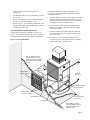
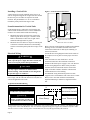
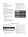
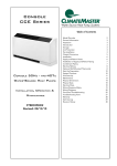
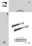
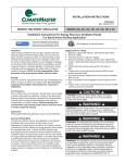
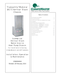
HS/HL/HP and VS/VL/VP Series
Horizontal & Vertical Series
Water Source Heat Pumps
Installation, Operation, &
Maintenance Instructions
TABLE OF CONTENTS
Page
Page 2
General Information
3
Inspection
3
Introduction
3
Storage
3
Unit Protection
3
Pre-Installation
3
Location and Access-Horizontal Units
4
Location and Access-Vertical Units
5
Installation
6
Installation of Supply and Return Piping
6
Condensate Piping
6
Hanging and Mounting a Horizontal Unit
7
Sound Attenuation for Horizontal Units
8
Installing a Vertical Unit
8
Sound Attenuation for Vertical Units
8
Electrical Wiring
8
Operating Limits
9
Starting Conditions
9
Start-Up Preparation
9
System Checkout
10
Unit Start-Up
11
Warranty
13
Maintenance
BC
Maintenance Procedures
BC
Safety Control Reset
BC
GENERAL INFORMATION
Inspection
Unit Protection
Upon receipt of shipment at the job site, carefully check
the shipment against the bill of lading. Make sure all
units have been received. Verify Hanger Brackets are
located inside the fan compartment of Horizontal Units.
Inspect the carton or crating of each unit, and inspect
each unit for damage. Assure that the carrier makes
proper notation of any shortages or damage on all copies
of the freight bill and he/she completes a Carrier
Inspection Report. Concealed damage not discovered
during unloading must be reported to the carrier within
15 days of receipt of shipment. Note: It is the
responsibility of the purchaser to file all necessary
claims with the carrier. Notify the ClimateMaster
Traffic Department of all damage within fifteen (15)
days of shipment.
Cover Horizontal and Vertical units on the job site with
either shipping cartons, vinyl film, or an equivalent
protective covering. Cap the open ends of pipes stored on
the job site. In areas where painting, plastering, or the
spraying of fireproof material has not been completed, all
due precautions must be taken to avoid physical damage
to the units and contamination by foreign material.
Physical damage and contamination may prevent proper
start-up and may result in costly equipment clean-up.
Introduction
This Installation, Operation and Maintenance Manual is
for ClimateMaster Horizontal and Vertical Water Source
Heat Pump systems (HS/HL/HP & VS/VL/VP).
ClimateMaster Horizontal Water Source Heat Pump (HS/
HL/HP) units are designed for installation above a false
ceiling or in a ceiling plenum. Vertical (VS/VL/VP) units
are typically installed in a floor level closet or in a small
mechanical room. The installation site chosen for these
units must allow adequate clearance for maintenance and
servicing of the unit without its removal from the
installation location.
Examine all pipes, fittings, and valves before installing
any of the system components. Remove any dirt found on
these components.
Pre-Installation
Installation, Operation and Maintenance (IOM)
instructions are provided with each unit. Before unit
start-up, read all manuals and become familiar with the
unit and its operation. Thoroughly check the system
before operation.
Prepare Horizontal and Vertical units for installation as
follows:
1.
Compare the electrical data on the unit nameplate
with ordering and shipping information to verify the
correct unit has been shipped.
2.
Keep both the chassis and the cabinet covered with
the shipping carton until installation is complete and
all plastering, painting, etc., is finished.
Refer to project submittal drawings for specific unit
technical data and wiring diagrams.
3.
Verify refrigerant tubing is free of kinks or dents and
it does not touch other unit components.
Storage
4.
Inspect all electrical connections. Connections must
be clean and tight at the terminals.
5.
Loosen compressor bolts on units equipped with
compressor spring vibration isolation until the
compressor rides freely on the springs. Remove
shipping restraints. Note: HP/VP units are not
spring mounted, no futher action is required.
6.
Some airflow patterns are field convertible. Contact
your local sales representative for specific
instructions.
! CAUTION
▲
DO NOT store or install Horizontal and Vertical units
in corrosive environments or in locations subject to
temperature or humidity extremes (e.g., attics,
garages, rooftops, etc.). Corrosive conditions and high
temperature or humidity can significantly reduce
performance, reliability, and service life. Always
move units in an upright position. Tilting units on
their sides may cause equipment damage.
Upon the arrival of equipment at the job site,
immediately store units in their shipping cartons in a
clean, dry area. Store units in an upright position at all
times. Stack Horizontal units a maximum of 4 units high.
Stack vertical units a maximum of 3 units high. DO NOT
remove equipment from shipping cartons until
equipment is required for installation.
To avoid equipment damage, DO NOT use these units
as a source of heating or cooling during the
construction process. The mechanical components
and filters used in these units will quickly become
clogged with construction dirt and debris which may
cause system damage.
Page 3
Horizontal Units Location and Access
To avoid the release of refrigerant into the
atmosphere, the refrigerant circuit of this unit MUST
only be serviced by technicians who meet local, state
and federal proficiency requirements.
All refrigerant discharged from this unit must be
recovered without exception. Technicians MUST
follow industry accepted guidelines and all local, state
and federal statutes for the recovery and disposal of
refrigerants.
When a compressor is removed from this unit, system
refrigerant circuit oil will remain in the compressor.
To avoid leakage of compressor oil, the refrigerant
lines of the compressor MUST be sealed after it is
removed.
Figure 1. Typical Horizontal Installation
Horizontal Units are typically installed above a false
ceiling or in a ceiling plenum. Refer to Figure 1 for an
illustration of a typical installation. Install units with
adequate clearance to allow maintenance and servicing
without removal of the unit from the ceiling. Conform to
the following guidelines when selecting unit location:
1.
Provide a hinged access door in concealed-spline or
plaster ceilings. Provide removable ceiling tiles in
T-bar or lay-in ceilings. Refer to submittal drawing
for Horizontal Unit Dimensions. Size the access
opening to accommodate the service technician
during the removal and replacement of the
compressor and the removal and installation of the
unit.
2.
Provide access to hanger brackets, water valves and
fittings. Provide screwdriver clearance to access
System Water In
System Water Out
Bar Joist
Stop Valves
(By others)
Balance/ Stop Valves
(By others)
Controls
Electrical
(By others)
High Pressure Flexible
Hose Kit (Optional)
Condensate Trap
(By others)
Filters
Access
Panels
Figure 2. Unit supported
by Portable Jack during
installation or replacement
Heat Pump
Portable Lifting Jack
with Manual Crank
Page 4
panels, discharge collars and all electrical
connections.
3.
Provide a duct slot for filter replacement, if a return
duct is used.
4.
DO NOT obstruct the space beneath the unit with
piping, electrical cables and other items.
5.
Refer to Figure 2. Use a manual portable jack to lift
the unit and to support the weight of the unit during
installation and servicing.
Vertical Units Location and Access
Vertical Units are typically installed in a floor level
closet or in a small mechanical room. Refer to Figure 3
for an illustration of a typical installation. Install units
Figure 3. Vertical Installation
Note: A minimum of 8" of
clearance must be provided
between unit and remote filter/
grille when no return air duct
is used.
with adequate clearance to allow maintenance and
servicing. Conform to the following guidelines when
selecting unit location:
1. Provide adequate clearance for filter replacement and
drain pan cleaning. DO NOT block filter access with
piping, conduit or other materials. Refer to submittal
drawing for Vertical Unit Dimensions.
2. Provide access for fan and fan motor maintenance
and for servicing the compressor and coils without
removal of the unit.
3. Provide an unobstructed path to the unit within the
closet or mechanical room to enable removal of the
unit, if necessary.
4. Provide access to water valves and fittings and
screwdriver access to the unit side panels, discharge
collar and all electrical connections.
Controls
System
Water Out
Remote Filter/
Grille (by others)
Electrical
(By others)
High Pressure Flexible
Hose Kit (Optional)
Balance/Stop
Valve (by others)
Condensate Trap
(By Others)
System Water in
Condensate
Note: Adequate clearance
must be provided on all sides
of unit when remote filter/
grille is not used.
Page 5
INSTALLATION
The installation of Horizontal and Vertical Water Source
Heat Pump units and all associated components, parts
and accessories which make up the installation shall be in
accordance with the regulations of ALL authorities
having jurisdiction and MUST conform to all applicable
Codes. It is the responsibility of the Installing Contractor
to determine and comply with ALL applicable Codes and
Regulations.
Maximum allowable torque for brass fittings is 30 footpounds. If a torque wrench is not available, tighten
finger-tight plus one quarter turn. Tighten steel fittings as
necessary.
Installation of Supply and Return Piping
DO NOT bend or kink supply lines or hoses.
! CAUTION
▲
Piping must comply with all applicable codes.
Follow these piping guidelines.
1.
Install a drain valve at the base of each supply and
return riser to facilitate system flushing.
2.
Install shut-off/balancing valves and unions at each
unit to permit unit removal for servicing.
3.
Place strainers at the inlet of each system circulating
pump.
4.
Select the proper hose length to allow slack between
connection points. Hoses may vary in length by +2%
to -4% under pressure.
5.
Refer to Table 1. DO NOT exceed the minimum
bend radius for the hose selected. Exceeding the
minimum bend radius may cause the hose to
collapse, which reduces water flow rate. Install an
angle adapter to avoid sharp bends in the hose when
the radius falls below the required minimum.
Table 1. Metal Hose Minimum Bend Radii
Hose in Inches
1/2
3/4
1
1-1/4
Minimum Bend Radius
2-1/2
4-1/2
5-1/2
6-3/4
Insulation is not required on loop water piping except where
the piping runs through unheated areas or outside the
building. Because loop temperature is normally between
60°F and 90°F, piping will not sweat nor suffer heat loss in
normal ambient conditions. (HS/VS and HL,HP/VL,VP
may require insulation if loopwater temperature drops
below the dew point.)
Pipe joint compound is not necessary when Teflon threaded
tape is pre-applied to hose assemblies or when flared-end
connections are used. If pipe joint compound is preferred,
use compound only in small amounts on the male pipe
threads of the fitting adapters. Prevent sealant from reaching
the flared surfaces of the joint. Note: When anti-freeze is
used in the loop, assure it is compatible with Teflon tape
or the pipe joint compound used.
Page 6
Ensure the trap is filled with water before operating the
unit to avoid condensate pan overflow at initial start-up.
Optional pressure-rated hose assemblies designed
specifically for use with ClimateMaster units are
available. Similar hoses can be obtained from alternate
suppliers. Supply and return hoses are fitted with swiveljoint fittings at one end to prevent kinking during
installation.
Refer to Figure 4 for an illustration of a Supply/Return
Hose Kit. Male adapters secure hose assemblies to the
unit and risers. Install hose assemblies properly and
check them regularly to avoid system failure, reduced
service life and possible damage to surrounding furniture
and carpets.
Figure 4. Supply/Return Hose Kit
Rib Crimped
Swivel
Brass
Fitting
Brass
Fitting
Length
(2 Foot Length Standard)
MPT
▲! CAUTION
Corrosive system water requires
corrosion-resistant fittings and hoses and may require
water treatment.
Condensate Piping
Units are typically installed directly above each other on
successive floors with condenste drains located near the
units.
Connect the unit condensate drain connection to the
building condensate drain with a flexible, non-pressurerated 3/4 inch ID plastic hose. Ensure the hose is without
kinks to maintain an unobstructed flow of condensate
from the unit to the drain.
The horizontal run of a condensate hose is usually too
short to cause drainage problems, however, the
horizontal run of the condensate line should be pinched
at least 1 inch for every 10 feet of run in the direction of
flow. Avoid low points and unpitched piping since dirt
collects in low or level areas and may cause stoppage and
overflow.
Install a condensate trap at each unit with the top of the
trap positioned below the unit condesate drain
connection.
Figure 5 illustrates a typical trap and vent used with
HS/HL/HP & VS/VL/VP Heat Pumps. Design the
length of the trap (water-seal) based upon the amount of
Figure 5. Condensate Drain
To avoid condensate overflow in Horizontal Units:
Horizontal Units sizes 006-030 must be hung level to
ensure proper condensate drainage. Horizontal Units sizes
036-120 must be hung pitched 1/4" to 1/2" toward the
condensate drain connection to ensure proper drainage.
RECOMMENDED TRAP DIMENSION
VENT
When Necessary
2”
Follow clearance guidelines described in the Location
and Access section of this manual. Provide adequate
clearance within the plenum for filter removal. When the
unit is installed with a return air plenum, provide a slot to
remove the filter.
Figure 6. Hanger and Vibration Isolation Kit
UNIT
1”
3/8" Threaded
Rod (By Others)
Hanger
PITCH DOWN TO DRAIN
1/4" PER FOOT
negative pressure on the drain pan. As a rule, 1" of trap
is required for each inch of negative pressure on the unit.
Each unit must be installed with its own individual trap
and connection to the condensate line (main) or riser.
Provide a means to flush or blow-out the condensate
drain line. DO NOT install units with a common trap
and/or vent.
Install a vent in the condensate line of any application
which may allow dirt or air to collect in the line. Always
vent when the application requires a long, horizontal run,
when some sagging in the condensate line may be
anticipated (as in a long line of plastic pipe) or when
"double trapping" may occur. Also vent when large
units are working against higher external static pressure
than other units connected to the same condensate main
since this may cause poor drainage for all units on the
line. When a vent is installed in the condensate line, it
must be located after the trap in the direction of
condensate flow.
Hanging or Mounting a Horizontal Unit
Horizontal heat pumps are typically suspended above a
ceiling or within a soffit using field-supplied, threaded
rods sized to support the weight of the unit.
A mounting kit including four (4) mounting brackets and
four (4) vibration isolators is shipped inside the blower
compartment of each unit.
Refer to Figure 6. Attach brackets and isolators to the
bottom corners of the unit. Use four (4) field-supplied
threaded rods to suspend the unit. Hang the unit clear of
the floor slab above and support the unit by the
mounting bracket assemblies only. DO NOT attach the
unit flush with the floor slab above.
Vibration
Isolator
Washer &
3/8" Hex Nut
(By Others)
Slot used for installation of
hangers with 096 and 120
models only. Screws used
must be 1/2" or less in length
Notes: 1. Kits shipped unassembled and bulk-packed (4
hanger assimblies per unit) 2. Total head space
required = unit height + 1/2 inch + condensate
trapping. 3. See unit dimensional drawings for further
information.
Sound Attenuation for Horizontal Units
Sound minimization is achieved by correct placement of
the unit. Place the units so principal sound emission is
outside the occupied, sound sensitive space.
Note: If a fire wall is penetrated, a fire damper may be
required by local codes.
Lowest sound levels are obtained if the discharge duct has
at least one 90˚ bend and the return is ducted. All ducts
should be internally insulated
Page 7
Figure 7. Vertical Sound Attenuation
Installing a Vertical Unit
Vertical units are typically installed on the floor or on
shelves designed to support the weight of the unit. Install
the unit on a piece of rubber or neoprene for sound
isolation. The pad should be 1/2" to 3/8" in thickness.
Extend the pad beyond all four edges of unit.
Sound Attenuation for Vertical Units
Sound minimization is achieved by enclosing the unit
within a small mechanical room or a closet. Additional
measures for sound control include the following:
1.
2.
Isolation Pad
Mount the unit so the return air inlet is 90° to the
return air grille. Refer to Figure 7. Install a sound
baffle as illustrated to reduce line of sight sound
transmitted through return air grilles.
Mount the unit on a rubber or neoprene isomode pad
to minimize vibration transmission to the building
structure. Extend the pad beyond all four edges of the
unit.
Electrical Wiring
WARNING
To avoid possible injury or death due to electrical
shock, open the power supply disconnect switch and
secure it in an open position during installation.
▲! CAUTION
Use only copper conductors for field installed
electrical wiring. Unit terminals are not designed to
accept other types of conductors.
All field installed wiring, including electrical ground,
must comply with the National Electrical Code (NEC) as
well as all applicable local codes.
Insulated Sound Baffle
(Open Both Ends and Bottom)
Return Air Louver or Grille
Refer to the unit wiring diagrams included with submittal
drawings for fuse sizes and a schematic of the field
connections which must be made by the installing (or
electrical) contractor.
Consult the unit wiring diagram located on the inside of
the compressor access panel to ensure proper electrical
hookup.
Units rated 208-230 volts which have a 24 Volt
transformer must have the transformer connection
modified if the actual power supply is 230 volts. Refer to
the unit wiring diagram for details of this procedure.
All final electrical connections must be made with a
length of flexible conduit to minimize vibration and
sound transmission to the building.
For additional wiring information pertinent to units
supplied with a ClimateMaster CMC-2000 Series Control
Board, refer to the CMC-2000 Series Installation,
Operation Manual (p/n 69626515) supplied with this
unit.
Typical Field Installed Wiring
! CAUTION
▲
A
Field Supplied
Disconnect Switch
USE COPPER CONDUCTORS ONLY
TO PREVENT EQUIPMENT DAMAGE.
WARNING
DISCONNECT ELECTRICAL POWER
SOURCE TO PREVENT INJURY OR
DEATH FROM ELECTRICAL SHOCK.
Heat Pump
B
Room Thermostat
A= Two power wires on single-phase units: three power wires on three-phase units. B= 1 heat /1 cool /Manual or Auto
Change-Over remote 24V thermostat. Note: All customer-supplied wiring to be copper only and must conform to NEC
and local electrical codes. Wiring shown with dashed lines must be field-supplied and field-installed.
Page 8
Operating Limits
4.
Determination of operating limits is dependent
primarily upon three factors: 1) return air
temperature, 2) water temperature and 3) ambient
temperature. When any one of these factors is at
minimum or maximum levels, the other two factors
should be at normal levels to ensure proper unit
operation (refer to Table 2).
5.
Extreme variations in temperature and humidity and
corrosive water or air will adversely affect unit
performance, reliability and service life.
Environment - This unit is designed for indoor
installation ONLY.
Power Supply - A voltage variation of +/- 10% of
nameplate utilization voltage is acceptable. Three-phase
system imbalance shall not exceed 2%.
Starting Conditions
HS/HL/HP & VS/VL/VP Units - HS/HL/HP& VS/VL/
VP Units start and operate in an ambient of 40°F with
entering air at 40°F, entering water at 70°F and both air
and water at the stated flow rates of ARI Standard 32086 rating test for initial winter start-up.
HL/HP & VL/VP Units - HL/HP & VL/VP Units start
and operate in an ambient of 40°F with entering air at
40°F, entering water at 40°F and both air and water at the
stated flow rates of ARI Standard 320-86 rating test for
initial winter start-up.
Notes
1.
These are not normal or continuous operating
conditions. It is assumed that winter start-up is to
bring the building space up to occupancy
temperatures.
2.
Voltage utilization range complies with ARI
Standard 110.
3.
When using 100 percent outside air as a source of
ventilation, a 40°F DB minimum (heating mode) and
a 78°F WB maximum (cooling mode) are
acceptable, but the cabinet may sweat during hot
weather.
Table 2 Operating Limit
HS/VS
Air Limits
Min. Ambient Air
Rated Ambient Air
Max. Ambient Air
Min. Entering Air
Rated Entering Air db/wb
Max. Entering Air db/wb
Water Limits
Min. Entering Water
Normal Entering Water
Max. Entering Water
HL/HP &VL/VP
Cooling Heating Cooling Heating
50°F
80°F
100°F
50°F
80/67°F
110/83°F
50°F
70°F
85°F
50°F
70°F
80°F
40°F
80°F
100°F
50°F
80/67°F
110/83°F
40°F
70°F
85°F
40°F
70°F
80°F
55°F
85°F
110°F
55°F
70°F
90°F
40°F
85°F
110°F
40°F
70°F
90°F
START-UP PREPARATION
System Cleaning and Flushing
3.
Open all air vents. Fill the system with water. DO
NOT allow system to overflow. Bleed all air from
the system. Check the system for leaks and repair
appropriately.
WARNING
4.
To prevent injury or death due to electrical shock or
contact with moving parts, open unit disconnect
before servicing unit.
Verify all strainers are in place. Start the pumps, and
systematically check each vent to ensure all air is
bled from the system.
5.
Verify make-up water is available. Adjust make-up
water appropriately to replace the air which was bled
from the system. Check and adjust the water/air level
in the expansion tank.
6.
Set the boiler to raise the loop temperature to
approximately 85°F. Open a drain at the lowest point
in the system. Adjust the make-up water replacement
rate to equal the rate of bleed.
Cleaning and flushing the unit is the single most
important step to ensure proper start-up and continued
efficient operation of the system.
Follow the instructions below to properly clean and flush
the system:
1.
Verify electrical power to the unit is disconnected.
2.
Install the system with the supply hose connected
directly to the return riser valve. Use a single length
of flexible hose.
Page 9
7.
Refill the system and add trisodium phosphate in a
proportion of approximately one pound per 150
gallons of water. Reset the boiler to raise the loop
temperature to about 100°F.
Horizontal and Vertical units. Refill the system and
bleed off all air.
9.
! CAUTION
▲
To avoid possible damage to piping systems
constructed of plastic piping, DO NOT allow loop
temperature to exceed 110°F.
Circulate the solution for a minimum of eight to 24
hours. At the end of this period, shut off the
circulating pump and drain the solution. Repeat
system cleaning, if desired.
8.
When the cleaning process is complete, remove the
short-circuited hoses. Re-connect the hoses to the
proper supply, and return the connections to each of the
Test the system pH with litmus paper. The system
water should be slightly alkaline (pH 7.5 to 8.5). Add
chemicals, as appropriate, to maintain acidity levels.
! CAUTION
▲
DO NOT use “Stop-Leak” or any similar chemical agent
in this system. Addition of these chemicals to the loop
water will foul the system and will inhibit unit operation.
10. When the system is successfully cleaned, flushed,
refilled and bled, check the main system panels, safety
cutouts and alarms. Set the controls to properly
maintain loop temperatures.
SYSTEM CHECKOUT
When the installation is complete and the system is cleaned and flushed, follow the System Checkout procedure outlined below:
❏
1. Voltage: Ensure voltage is within the utilization
range specifications of the unit compressor and fan
motor.
❏
8. System Controls: To ensure no catastrophic system
failures occur, verify system controls are
functioning and the sequencing is correct.
❏
2. System Water Temperature: Ensure it is within
an acceptable range to facilitate start-up. (When
conducting this check, also verify proper heating
and cooling set points.)
❏
9. Freeze Protection for Water System: Verify
freeze protection is provided for the outdoor portion
of the loop water system. Inadequate freeze
protection can cause system operating problems.
❏
3. System Water pH: Verify system water acidity
(pH = 7.5 or 8.5). Proper pH promotes the
longevity of hoses and heat exchangers.
❏
4. System Flushing: Properly clean and flush system
periodically. Ensure all supply and return hoses are
connected end-to-end to facilitate system flushing
and prevent fouling of the heat exchanger by
system water. Water used in the system must be of
potable quality and clean of dirt, piping slag, and
chemical cleaning agents.
❏
❏
❏
5. Closed-Type Cooling Tower (Open Tower with
Heat Exchanger): Check equipment for proper
temperature set points and operation.
6. Balanced Water Flow Rate to Heat Pump:
Verify the inlet and outlet water temperatures are
recorded as each heat pump unit is started. This
check will eliminate nuisance unit trip-outs
resulting from water velocities which are either too
low or too high; it can also prevent the occurrence
of erosive water flow rates.
! CAUTION
▲
To avoid equipment damage, DO NOT leave system filled
in a building without heat during the winter unless antifreeze is added to system water. Condenser coils never
fully drain by themselves and will freeze unless winterized
with anti-freeze.
❏
10. System Water Loop: Verify all air is bled from the
system. Air in the system impedes unit operation
and causes corrosion in the system piping.
❏
11. Unit Filters: To avoid system damage, ensure the
unit filter is clean.
❏
12. Unit Fans: Manually rotate fans to assure free
rotation. Ensure fans are properly secured to the fan
shaft. DO NOT oil fan motors on start-up since they
are lubricated at the factory.
❏
13. System Control Center: To ensure control of the
temperature set-points for operation of the system’s
heat rejector and boiler, examine the system control
and alarm panel for proper installation and
operation.
❏
14. Miscellaneous: Note any questionable aspects of
the installation.
7. Standby Pump: Verify the standby pump is
properly installed and in operating condition.
Page 10
UNIT START-UP
Use the procedure below to initiate proper unit start-up:
WARNING
a.
When the disconnect switch is closed, high voltage is
present in some areas of the electrical panel. Exercise
caution when working with energized equipment.
1.
Adjust all valves to their full open position. Turn on
the line power to all heat pump units.
2.
Operate each unit in the cooling cycle. Room
temperature should be approximately 70° to 75°F
DB, and 61° to 65°F WB. Loop water temperature
entering the heat pumps should be between 70°F and
110°F.
If the unit has an optional MCO thermostat, set the
temperature indicator to the highest setting and set
the selector switch to HEAT. The fan and the
compressor should start.
If the unit has an optional ACO thermostat, set the
temperature indicator to the far right setting, and set
the selector switch to AUTO. The fan and the
compressor should start.
b.
Once the unit has begun to run, check for warm air
delivery at the unit grille. List the serial number of
any machines which do not function.
4.
When the unit is operating in the cooling mode
under ARI conditions, the leaving water temperature
is approximately 10°F warmer than the entering
water temperature at 3 GPM / ton.
Establish a permanent operating record by logging
the unit operating conditions at initial start-up for
each unit.
5.
If a unit fails to operate, conduct the following
checks:
Note: Three factors determine the operating limits of
a Horizontal and Vertical unit: (1) return air
temperature, (2) water temperature and (3) ambient
temperature. When any one of these factors is at a
minimum or maximum level, the other two factors
must be at normal levels to ensure proper unit
operation.
a.
Check the voltage and current. They should comply
with the electrical specifications described on the
unit nameplate.
b.
Look for wiring errors. Check for loose terminal
screws where wire connections have been made on
both the line and low-voltage terminal boards.
c.
Check for dirty filters. A clogged filter will cause
safety cutouts to stop unit operation.
d.
Check the supply and return piping. They must be
properly connected to the inlet and outlet
connections on the unit.
For heat pumps with an optional ACO
thermostat, adjust the cooling set point to a
temperature at least 3°F below room
temperature.
e.
Check the fan. If the fan fails to operate, verify the
fan wheel turns freely and is secured to the shaft.
Also verify the fan operates in both heating and
cooling modes.
b.
Check for cool air delivery at the unit grille within a
few minutes after the unit has begun to operate. List
the identification number of any machines which do
not function.
f.
If the checks described above fail to reveal the
problem and the unit still will not operate, contact a
trained service technician to ensure proper diagnosis
and repair of the equipment.
c.
Check the elevation and cleanliness of the
condensate lines. Dripping may be a sign of a
blocked line.
3.
Operate each heat pump in the heating cycle
immediately after checking cooling cycle operation.
A time delay will prevent the compressor from restarting for approximately three minutes.
a.
Turn the unit thermostat to the coolest position. If
the unit has an optional MCO thermostat, set the
selector switch to COOL. Both the fan and
compressor should run.
Note: Horizontal and Vertical heat pumps are
designed to start heating at a minimum return air
temperature of 50°F with normal water flow rate and
ambient temperature.
Page 11
Page 12
CLIMATE MASTER, INC.
LIMITED EXPRESS WARRANTY/ LIMITATION OF REMEDIES AND LIABILITY
It is expressly understood that unless a statement is specifically identified as a warranty, statements made by Climate Master, Inc., a Delaware corporation, (“CM”) or its representatives, relating to CM’s products, whether oral,
written or contained in any sales literature, catalog or agreement, are not express warranties and do not form a part of the basis of the bargain, but are merely CM’s opinion or commendation of CM’s products. EXCEPT AS
SPECIFICALLY SET FORTH HEREIN, THERE IS NO EXPRESS WARRANTY AS TO ANY OF CM’S PRODUCTS. CM MAKES NO WARRANTY AGAINST LATENT DEFECTS. CM MAKES NO WARRANTY
OF MERCHANTABILITY OF THE GOODS OR OF THE FITNESS OF THE GOODS FOR ANY PARTICULAR PURPOSE.
GRANT OF LIMITED EXPRESS WARRANTY
CM warrants CM products purchased and retained in the United States of America and Canada to be free from defects in material and workmanship under normal use and maintenance as follows: (1) All complete air conditioning,
heating and/or heat pump units built or sold by CM for twelve (12) months from date of unit start-up or eighteen (18) months from date of shipment (from factory), whichever comes first; (2) Repair and replacement parts, which are
not supplied under warranty, for ninety (90) days from date of shipment (from factory). All parts must be returned to CM’s factory in Oklahoma City, Oklahoma, freight prepaid, no later than sixty (60) days after the date of the failure
of the part; if CM determines the part to be defective and within CM’s Limited Express Warranty, CM shall, when such part has been either replaced or repaired, return such to a factory recognized dealer, contractor or service
organization, F.O.B. CM’s factory, Oklahoma City, Oklahoma, freight prepaid. The warranty on any part repaired or replaced under warranty expires at the end of the original warranty period.
This warranty does not cover and does not apply to: (1) Air filters, fuses, refrigerant, fluids, oil; (2) Products relocated after initial installation; (3) Any portion or component of any system that is not supplied by CM, regardless of
the cause of the failure of such portion or component; (4) Products on which the unit identification tags or labels have been removed or defaced; (5) Products on which payment to CM is or has been in default; (6) Products which
have defects or damage which result from improper installation, wiring, electrical imbalance characteristics or maintenance; or are caused by accident, misuse or abuse, fire, flood, alteration or mis-application of the product; (7)
Products which have defects or damage which result from a contaminated or corrosive air or liquid supply, operation at abnormal temperatures, or unauthorized opening of refrigerant circuit; (8) Products subjected to corrosion or
abrasion; (9) Products manufactured or supplied by others; (10) Products which have been subjected to misuse, negligence or accidents; (11) Products which have been operated in a manner contrary to CM’s printed instructions; or,
(12) Products which have defects, damage or insufficient performance as a result of insufficient or incorrect system design or the improper application of CM’s products.
CM is not responsible for: (1) The costs of any fluids, refrigerant or other system components, or associated labor to repair or replace the same, which is incurred as a result of a defective part covered by CM’s Limited Express
Warranty; (2) The costs of labor, refrigerant, materials or service incurred in removal of the defective part, or in obtaining and replacing the new or repaired part (except for the limited labor coverage set forth above); or, (3)
Transportation costs of the defective part from the installation site to ClimateMaster or of the return of any part not covered by CM’s Limited Express Warranty.
Limitation: This Limited Express Warranty is given in lieu of all other warranties. If, notwithstanding the disclaimers contained herein, it is determined that other warranties exist, any such express warranty, including without
limitation any express warranties or any implied warranties of fitness for particular purpose and merchantability shall be limited to the duration of the Limited Express Warranty.
LIMITATION OF REMEDIES
In the event of a breach of the Limited Express Warranty, CM will only be obligated at CM’s option to repair the failed part or unit or to furnish a new or rebuilt part or unit in exchange for the part or unit which has failed. If
after written notice to CM’s factory in Oklahoma City, Oklahoma of each defect, malfunction or other failure and a reasonable number of attempts by CM to correct the defect, malfunction or other failure and the remedy fails of
its essential purpose, CM shall refund the purchase price paid to CM in exchange for the return of the sold good(s). Said refund shall be the maximum liability of CM. THIS REMEDY IS THE SOLE AND EXCLUSIVE
REMEDY OF THE BUYER AGAINST CM FOR THE BREACH OF CONTRACT, FOR THE BREACH OF ANY WARRANTY OR FOR CM’S NEGLIGENCE OR IN STRICT LIABILITY.
LIMITATION OF LIABILITY
CM shall have no liability for any damages if manufacture’s performance is delayed for any reason or is prevented to any extent by any event such as, but not limited to any war, civil unrest, government restrictions or restraints,
strikes or work stoppages, fire, flood, accident, shortage of transportation, fuel, material, or labor, acts of God or any other reason beyond the sole control of CM. CM EXPRESSLY DISCLAIMS AND EXCLUDES ANY
LIABILITY FOR CONSEQUENTIAL OR INCIDENTAL DAMAGE IN CONTRACT, FOR BREACH OF ANY EXPRESS OR IMPLIED WARRANTY, OR IN TORT, WHETHER FOR NEGLIGENCE OR AS
STRICT LIABILITY.
OBTAINING WARRANTY PERFORMANCE
Normally, the contractor or service organization who installed the products will provide warranty performance for the owner. Should the installer be unavailable, contact any CM recognized dealer, contractor or service
organization. If assistance is required in obtaining warranty performance, write or call:
Climate Master, Inc. • Customer Service • 7300 S.W. 44th Street • Oklahoma City, Oklahoma 73179 (405) 745-6000
LC083
*LC083*
NOTE: Some states or Canadian provinces do not allow limitations on how long an implied warranty lasts, or the limitation or exclusions of consequential or incidental damages, so the foregoing exclusions and limitations may not
apply to you. This warranty gives you specific legal rights, and you may also have other rights which vary from state to state and from Canadian province to Canadian province.
Please refer to the CM Installation, Operation and Maintenance Manual for operating and maintenance instructions.
Rev.: 10/00
Page 13
Page 14
Page 15
MAINTENANCE
Maintenance Procedures
Perform the maintenance procedures outlined below
periodically, as indicated.
WARNING
To prevent injury or death due to electrical shock or
contact with moving parts, open unit disconnect
switch before servicing unit.
Unit Inspection: Visually inspect the unit annually. Pay
special attention to hose assemblies. Repair any leaks and
replace deteriorated hoses immediately.
Compressor: Conduct an amperage check on the
compressor annually. Amperage draw should not exceed
normal full load or rated load amps by more than 10
percent of the values noted on the unit nameplate.
Maintain a log of amperage values to detect deterioration
prior to component failure.
Filters: Inspect filters. Establish a regular maintenance
schedule. Clean filter, and maintenance frequently
depending upon need.
To remove the filter from a Horizontal and Vertical unit,
slide the filter out of its frame located in the return air
opening at the bottom front of the unit. When reinstalling the filter, use the slide-in rails of the filter
frame to guide the filter into the proper position.
When replacing the compressor contactor or lockout
relay in a unit with electromechanical controls, use
only ClimateMaster replacement parts. Substitution
of other components may result in an inoperative
safety circuit and may cause a hazardous condition.
! CAUTION
▲
Heat Exchangers: Clean heat exchangers annually. Inspect
heat exchangers regularly, and clean more
frequently if the unit is located in a “dirty” environment.
To avoid fouled machinery and extensive unit cleanup, DO NOT operate units without filters in place.
DO NOT use equipment as a temporary heat source
during construction.
Condensate Pans: Check condensate drain pans for
algae growth every three months. If algae growth is
apparent, consult a water treatment specialist for proper
chemical treatment. The application of an algaecide
every three months will typically eliminate algae
problems in most locations.
Fan Motors: Lubricate fan motors annually. All
ClimateMaster Horizontal and Vertical units are fully
lubricated at the factory. DO NOT oil during installation.
Conduct amperage checks annually. Amperage draw
should not exceed normal full load or rated load amps by
more than 10 percent of the values noted on the unit
nameplate. Maintain a log of amperage values to detect
deterioration prior to component failure.
Safety Control Reset
All ClimateMaster Horizontal and Vertical units are
furnished with high and low pressure cutouts to prevent the
machine from operating at abnormal or damaging
temperature or water flow conditions.
The contacts of the high-pressure control used on Horizontal
and Vertical units are designed to open at 380 psig and
automatically close at 300 psig. The contacts of the lowpressure switch open at 10 psig and close at 32 psig. The
contacts of the low-temperature switch open at
33.5°F and re-close at 45°F. A lockout relay, electrically
linked with these cutouts, interrupts unit operation. The unit
must be reset manually.
Note: If the unit must be reset more than twice, check
the unit for a dirty filter, abnormal entering water
temperature, inadequate or excessive water flow and
internal malfunction. If the unit continues to cutout,
contact a trained service technician.
7300 S.W. 44th Street
Oklahoma City, OK 73179
Phone: 405-745-6000
Fax: 405-745-6058
www.climatemaster.com
*69197301*
Part #: 69197301
ClimateMaster works continually to improve its products. As a result, the design and specifications of each product at the time of order may be changed
without notice and may not be as described herein. Please contact ClimateMaster’s Customer Service Department at 1-405-745-6000 for specific
information on the current design and specifications. Statements and other information contained herein are not express warranties and do not form the
basis of any bargain between the parties, but are merely ClimateMaster’s opinion or commendation of its products.
© ClimateMaster 1994
Rev.: 4/01