1
Model 7000
Model 7000XL
Model 8000XL
Digital Scale
INSTRUCTION MANUAL
DORAN SCALES, INC.
1315 PARAMOUNT PKWY.
Batavia, IL 60510
1-800-262-6844
FAX: (630) 879-0073
http://www.doranscales.com
MANUAL REVISION: 3.1
MAN0190
Made in USA
7/07/2003
Table of Contents
Table of Contents.......................................................................................1
Introduction ................................................................................................4
Quick Start User's Guide ...........................................................................5
Fig. 1: Model 7000 Front Panel Layout ..................................................................... 5
Model 7000: ................................................................................................................. 5
Fig. 2: Model 7000XL Front Panel Layout ................................................................. 5
Model 7000XL: .......................................................................................................... 6
Fig. 3: Model 8000XL Front Panel Layout ................................................................. 6
Model 8000XL: ............................................................................................................. 6
Power Up: .................................................................................................................... 6
Basic Weighing Operation:........................................................................................... 7
Turn Off: (8000XL) ....................................................................................................... 7
Low Battery Indication: (8000XL) ................................................................................. 7
Electrical Connections:................................................................................................. 7
Zero:............................................................................................................................. 7
Units: ............................................................................................................................ 8
Print:............................................................................................................................. 8
Battery Operation: (8000XL) ........................................................................................ 8
Quick Setup Guide .....................................................................................9
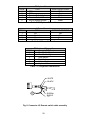
Fig. 4: Load Cell connections .................................................................................... 9
Load Cell and Power Connections: .............................................................................. 9
Option Connections:..................................................................................................... 9
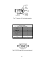
Fig. 5: Serial Communications and Remote Push Button Connections................... 10
Re-assembling Rear Cover: ....................................................................................... 10
Entering Calibrations and Parameter setup Mode:.................................................... 10
Capacity: .................................................................................................................... 11
Calibration: ................................................................................................................. 11
A/D Ranging: .............................................................................................................. 12
Table 1: Calibration requirements in raw counts ..................................................... 12
Parameter Setup.......................................................................................13
Entering and Exiting the Calibration and Parameter Setup Mode: ............................. 13
Stepping through the menu parameters: .................................................................... 14
Changing a Parameter: .............................................................................................. 14
Quick Review of Setup Parameters:........................................................................... 14
Legal for Trade Restrictions: ...................................................................................... 14
Audit Counters: .......................................................................................................... 14
Setup Menus Explained...........................................................................15
Capacity Setup Menu .............................................................................................. 16
Calibration Menu ..................................................................................................... 17
Digital Filter Setup Menu ......................................................................................... 18
Automatic Zero Tracking Setup Menu ..................................................................... 18
Motion Aperture Setup Menu .................................................................................. 19
Start Up Zero Setup Menu ...................................................................................... 19
Latching Zero Request Setup Menu........................................................................ 19
1
Latching Print Request Setup Menu........................................................................ 19
Printer Data Output Setup Menu ............................................................................. 20
Output Formats ....................................................................................................... 20
Baud Rate Setup Menu ........................................................................................... 20
Serial Data Handshaking Setup Menu .................................................................... 21
Units Conversion Setup Menu................................................................................. 21
Start Up Units Selection Menu ................................................................................ 21
Push-button Function Setup Menu .......................................................................... 22
Remote Push-button Configuration Menu ............................................................... 22
Legal For Trade Setup Menu .................................................................................. 22
Scale Resolution Setup Menu ................................................................................. 22
Unit On Timer (8000XL only)................................................................................... 23
Default all Scale Parameter settings ....................................................................... 23
Raw Counts Display Mode ...................................................................................... 23
Calibration and Parameter Menu Exit...................................................................... 23
Data Communications .............................................................................24
Introduction to data communications:......................................................................... 24
Printer Modes: ............................................................................................................ 25
Transmit on demand (tod): ........................................................................................ 25
Continuous print (CP): ................................................................................................ 25
Auto Print 1 (AP1): ....................................................................................................... 25
Auto Print 2 (AP2): ...................................................................................................... 25
Data output format:..................................................................................................... 26
"F0" Format: .............................................................................................................. 26
"2d" Format: .............................................................................................................. 26
"SSP" format:............................................................................................................... 26
"Fg" Format:............................................................................................................... 26
Table 2: Doran serial protocol ................................................................................. 27
Specifications and Interconnect Data ....................................................28
Specifications: ............................................................................................................ 28
Table 3: Scale Specifications .................................................................................. 28
Interconnect Data: ...................................................................................................... 28
Table 4: TB1 Load Cell Connections....................................................................... 28
Table 5: P2 Options Connections............................................................................ 29
Table 6: J1 Power Connections............................................................................... 29
P3 Keyboard Connections....................................................................................... 29
Table 7: P3 Keyboard Connections......................................................................... 29
Fig. 6: Connector J2, Remote switch cable assembly ............................................. 29
Fig. 7: Connector J2, Serial cable assembly ........................................................... 30
Table 8: Serial Output pin description ..................................................................... 30
Fig. 8: RS232 Output DB9 Connector (optional) ..................................................... 30
Fig. 9: Installation of EMI / RFI / ESD protection devices. ....................................... 31
Fig. 10: Jumpers and Connector Locations............................................................. 32
Table 9: Board Jumper settings............................................................................... 32
4-20mA Analog Output (optional)...........................................................33
Introduction ................................................................................................................ 33
Setup.......................................................................................................................... 33
Operation ................................................................................................................... 33
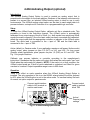
Fig. 11: 4-20mA analog option board ...................................................................... 33
2
Troubleshooting.......................................................................................34
General problem resolution: ....................................................................................... 34
Resetting the scale parameters:................................................................................. 35
Resetting the scale:.................................................................................................... 35
Scale Messages: ........................................................................................................ 36
Error messages: ......................................................................................................... 36
Replacement Part List .............................................................................37
Warranty Statement .................................................................................41
3
Introduction
Introducing the Doran Scales, Inc. Model 7000, 7000XL, 8000XL Digital Scale Indicator.
This scale uses state of the art technology to provide you with a low cost solution to the
most demanding weighing applications. With ease of use and setup in mind, the scale is
simple to set up and ready to use. The Model 7000, 7000XL, 8000XL offers many
features. A few of these features are listed below:
NTEP certification for Class III installations to 10,000d (CoC 99-129).
A six digit, 0.56" red LED display for easy reading.
lb, kg, oz, g, lb-oz display units supported.
Fully configurable duplex printer port with RS232 support.
EEPROM nonvolatile data storage of all calibration and setup information.
Microprocessor monitoring system to prevent scale failure under severe fault
conditions.
Support for up to four 350 ohm load cells.
115/230 VAC 50/60 Hz (jumper selectable) operation.
Field selectable digital filtering.
Software configurable remote push-button support (Optional).
Non NTEP parameters are user configurable.
Password protected, Front Panel Calibration Access Feature (Optional on
7000).
60 hour of battery operation, with built in charger (8000XL).
Six digit, 0.56" red LED remote display (Optional).
4-20mA analog output (Optional).
Please be sure to read the entire manual to ensure obtaining all the benefits that the
Model 7000, 7000XL, 8000XL can provide. If any questions arise, please feel free to
contact the Doran Scales Technical Support Department at 1-800-262-6844.
Unpacking Your Scale
Before unpacking your Doran scale, please read the instructions in this section. Your
new scale is a durable industrial product, but it is also a sensitive weighing instrument.
Normal care should be taken when handling and using this product. Improper handling
or abuse can damage the scale and result in costly repairs that will not be covered by
the warranty. If you notice any shipping damage, notify the shipper immediately. Please
observe the following precautions to insure years of trouble free service from your new
scale.
DO NOT drop the scale.
DO NOT immerse the scale.
DO NOT drop objects on the platform.
DO NOT pick up the scale by the "spider."
Carefully remove the scale from the shipping carton.
4
Quick Start User's Guide
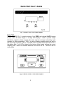
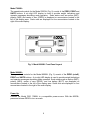
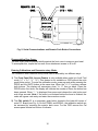
Fig. 1: Model 7000 Front Panel Layout
Model 7000:
The Model 7000 (Fig. 1) controls consist of the ZERO and optional UNITS buttons
located under the main display. A six-digit LED display is used to provide weight
indications, negative polarity (except lb/oz) and operator messages describing scale
operation. A status annunciator, "NEG," is used to display negative polarity as well as
the minus sign (except in lb & oz). The "NEG" LED is located in the lower left corner of
the display area. Four LED's located at the bottom of the display indicate the current
weighing units. Motion is indicated when the units LED's are off. The LED's are on
when stable.
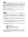
Fig. 2: Model 7000XL Front Panel Layout
5
Model 7000XL:
The operational controls for the Model 7000XL (Fig. 2) consist of the ZERO, PRINT and
UNITS buttons. A six digit LED display is used to provide weight indications and
operator messages describing scale operation. Scale status such as motion (MOT),
polarity (NEG) and center of zero (ZERO) is displayed on annunciators located to the
left of the display area. Scale units are displayed on four annunciators located to the
right of the main display.
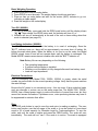
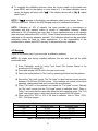
Fig. 3: Model 8000XL Front Panel Layout
Model 8000XL:
The operational controls for the Model 8000XL (Fig. 3) consist of the ZERO (on/off),
PRINT and UNITS buttons. A six digit LED display is used to provide weight indications
and operator messages describing scale operation. Scale status such as motion (MOT),
polarity (NEG), center of zero (ZERO), and low battery (BATT) are displayed on
annunciators located to the left of the display area. Scale units are displayed on four
annunciators located to the right of the main display.
Power Up:
Connect the Model 7000, 7000XL to a compatible power source. With the 8000XL,
press and release ZERO to turn on scale.
6
Basic Weighing Operation:
1) Remove all items from the scale platter.
2) Press ZERO to zero the scale. The weight display should now read zero.
3) Place an item on scale platter and wait for the motion (MOT) indicator to go out,
indicating a stable weight.
4) Read the weight on the scale display.
Turn Off: (8000XL)
1) To turn off manually, press and hold the ZERO push button until the display shows
"
" Then release, the ZERO button and, the indicator will turn off, or…
2) Indicator will turn off automatically at the end of the unit on timer setting when that
mode is selected (see page 23).
rEL Pb.
Low Battery Indication: (8000XL)
The "BATT" indicator indicates that the battery is in need of recharging. Once the
"BATT" indicator turns on, there will be approximately one more hour of battery life
before the scale shuts down. When the battery is too low to run the scale, the Model
8000XL simply turns off and will not operate again until the battery is recharged. The
Model 8000XL remains accurate and useable even with the "BATT" indicator on.
Note:Battery life can vary depending on the following:
The operating temperature.
If optional remote display is installed.
Whether or not the battery is fully charged after each low battery event.
Load cell input impedance.
Electrical Connections:
Prior to connecting your Model 7000, 7000XL, 8000XL to power, check the serial
number tag on the scale for the correct operating voltage. Verify that the power matches
the rated voltage.
Be sure the AC power is not excessively noisy - this can occur if large inductive loads,
such as solenoids or motors, are on the same power line. The Model 7000, 7000XL,
8000XL has a filtered power supply to reduce the effects of normal line noise, but they
cannot limit severe fluctuations. If problems occur, noise producing devices may have to
be suppressed to minimize their effect.
Zero:
The ZERO push button is used to zero the scale prior to making a reading. The zero
button can function over the full range of the scale or it can be limited to a zero band
equal to 4% of scale capacity for Canadian Legal for Trade applications. To zero the
scale, wait until the scale is stable and press the ZERO button. The scale will zero
immediately. The scale will not "zero" if the scale is in motion. The scale is equipped
7
with an optional "Zero on Demand" feature which holds "zero" requests until motion
stops. This option may be activated during the scale setup procedure.
Units:
The UNITS button permits the operator to change the 7000XL, 8000XL, and
7000(optional) units by pressing a button. After pressing UNITS, the next display
update will indicate the correct weight in the new units. The UNITS button has several
configuration parameters, which can disable the UNITS button or limit the display units
available.
Print:
The PRINT button permits the operator to send data to a printer or other external
devices. Like the ZERO button, the user must wait for motion to stop before pressing
the PRINT button. The current weight will then be transmitted to the printer. The
7000XL, 8000XL, and 7000(optional) has a "Print on Demand" feature which stores a
PRINT request until the scale is stable. Once stable, the scale transmits the current
weight. These models also have several automatic print options, which may be used to
simplify printer operation.
Battery Operation: (8000XL)
The 8000XL is equipped with a self-contained rechargeable, sealed, gelled-electrolyte
battery and charging circuit, both internal. The 8000XL is designed to run continuously
for 60 hours (with one 350 ohm loadcell) on a fully charged battery. The charging circuit
will fully charge the battery in approximately four hours. To charge the battery, simply
plug the line cord into a standard 115V (230V optional) wall outlet.
The 8000XL can be used while recharging the battery, in fact, the 8000XL can be used
with the AC charger cord plugged in on a continuous basis. A full recharge takes four
hours, whether the 8000XL is on or off.
If an AC power failure occurs with the charger plugged in, the 8000XL battery
immediately takes over to provide uninterrupted scale operation for up to 60 hours.
The 8000XL's charging circuit is a two-stage, current limited type charger. The 8000XL
will sense the charge condition of the battery and charge at a high rate when the battery
is depleted. When the battery comes up to a fully charged state, the charger will switch
to a "float" or "trickle" mode which maintains the battery at a fully charged state without
overcharging.
The "BATT" indicator indicates that the battery is in need of recharging. The 8000XL
will continue to operate accurately for approximately four hours (with one 350 ohm
loadcell) after "BATT" is lit. When the battery is too low to run the scale, the 8000XL
simply turns off and will not operate again until the battery is recharged. At this point,
when ZERO (ON/OFF) is pressed, the "BATT" indicator will be lit as the 8000XL
performs its display test and then the scale will shut down immediately. This eliminates
any potential scale errors.
8
Quick Setup Guide
Remove factory installed
shipping jumper.
S/N
ZERO
ZERO P3B
+ Signal
- Signal
+ Excitation
- Excitation
CAL
S1
S3
CAL
+ Sense
UNITS
S2
- Sense
S4
UNITS
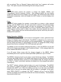
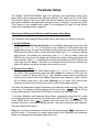
Remove JU7 and JU8 when connecting a 6wire load cell. (JU7 and JU8 must be present
when connecting to a 4-wire loadcell)
CAL S3
Fig. 4: Load Cell connections
Load Cell and Power Connections:
Load cell connections are made through a terminal block located at the bottom center of
the main PC. Board. The power cord connects to a connector adjacent to the
transformer. These connections are accessible by removing the rear cover screws and
laying the rear cover and main board on the work surface. Locate the ferrite core kit and
read "load cell cable grounding and ferrite assembly" instruction sheet. Thread loadcell
wires through the ferrite core as shown in Fig. 9. Connect load cell per Fig. 4.
Option Connections:
The Remote Switch and Serial Communications connector is found on the topside of
the main PC. Board. This connection is accessed by removing the rear cover.
Connections are made by either crimping (or soldering) a connector contact onto each
lead of the option cable. After crimping (or soldering), the contact is pressed into a
connector housing. The completed option connector is then snapped onto the option
connector found on the main board. Like the load cell cable and power cord, the option
cables are passed through watertight fittings mounted on the back of the indicator.
9
Fig. 5: Serial Communications and Remote Push Button Connections
Re-assembling Rear Cover:
The rear cover must be pressed solidly against the front cover to ensure a good seal.
To accomplish this, torque the four rear cover attachment screws to 20 in-lb.
Entering Calibrations and Parameter setup Mode:
The Calibration and Parameter Setup Mode can be entered by two different ways.
1) The Front Panel CAL Access Feature is only available when scale is in Audit Trail
mode (“ ” = “ ”, “ ”, “ ”). This feature is not available on 7000 without the units
push button option. To enter the calibration mode, power up scale while pressing the
ZERO and the UNITS button at the same time. When the “
” is shown, release
both buttons. The display will momentary show “
” then go blank. Press the
ZERO button five times, the display will indicate the number of times the button has
been pressed. When “ “ is displayed then press and release the units button and
wait a few seconds. Note: If the code is not entered before the timer is finished, the
scale will bypass code entry and enter the normal run mode.
oP
Std 44 CAn
rEL Pb
Ent Cd
5
2) The CAL switch S1 is a momentary push button located in the lower left corner of
main PC. Board (see Fig. 4). On the 7000XL and 8000XL, the calibration switch can
be accessed by removing the meter’s back cover. For the 7000 remove the Cal
access panel located on bottom of indicator.
10
Capacity:
Capacity selection is performed by entering in the Calibration mode, then press and
release UNITS until "
XX" appears on the display (where "XX" can be any valid
capacity). Once the CAP prompt appears press and release ZERO until the desired
capacity is displayed. When finished, return to the run mode by pressing the CAL
switch again or scroll through the menu with the UNITS button to "
" and select
" with the ZERO button, then press the UNITS button.
"
CAP
donE n
donE 4
Once the desired capacity has been selected, place the correct capacity label on the
front panel, to the right of the display.
NOTE: On scales with factory installed platforms, the capacity is set at the factory. It
will not be necessary to set the scale capacity.
Calibration:
1) Enter Calibration mode, then press and release the UNITS until "
" appears on
the display.
2) Remove all weight from the scale platter and wait for about 10 seconds. Press
ZERO and wait for the display to count down to 0. If the calibration zero was in
". If the display returns with a "
". Repeat
range, the display will return with "
the process.
CAL 0
CAL FS
CAL 0
NOTE: If "
" appears on the display, the calibration zero is out of range. Press
ZERO to clear error. Refer to the A/D Ranging section for additional information.
rg Err
3) The scale can be calibrated using (a) full capacity weight, (b) half capacity, (c)
quarter capacity, (d) one tenth capacity, or (e) any capacity weight between 2% and
100% of full scale (7000XL and 8000XL only).
To select the weight to calibrate the scale, press the UNITS button and select one of the
four following capacities.
CAL
CAL
CAL
CAL
FS: Full load calibration.
.50: Half load calibration. (50% of full load)
.25: Quarter load calibration. (25% of full load)
.10: 1/10th load calibration. (10% of full load)
If you want to use a weight between 10% and 100% of capacity, not 25% or 50%, select
the capacity above the closest to the desired weight (do not use
). Then scroll to
the exact weight by pressing CAPACITY to go higher or PRINT to go lower. This is not
available on the Model 7000.
CAL FS
11
4) To complete the calibration process, place the correct weight on the platter and
press ZERO, wait for the display to count down to 0. If the span calibration was in
range, the display will return with "
". If the display returns with a "
", repeat
steps 2 and 3.
donE
CAL 0
NOTE: If "
" appears on the display, the calibration span is out of range. Press
ZERO to clear error. Refer to the A/D Ranging section for additional information.
SPAn E
NOTE: Calibration at 10% of capacity has been provided as a convenience to
customers with high capacity scales in remote or inaccessible locations. Scales
calibrated at 10% of capacity are more likely to have significant errors at full capacity
than are scales calibrated at 25% or 50%. Doran Scales recommends that all scales be
calibrated at full capacity whenever possible. 10% calibration should not be used when
calibrating scales for legal for trade applications. It is the responsibility of the
installer/user to ensure that NTEP accuracy is achieved after any calibration.
A/D Ranging:
(Refer to this section only if you encounter a calibration problem)
NOTE: On scales with factory installed platforms, the zero and span will lie within
permissible limits.
1) Enter Calibration mode by using Front Panel CAL Access feature or by
pressing the CAL switch (S1).
2) Press and release UNITS until in the raw counts mode.
3) Return the scale platform to "No Load" by removing all items from the platform.
4) Record the "No Load" counts. The "No Load" or dead load raw counts must be
between 130,000 and 393,000 counts. If the readings are outside of the limits
specified, change dead load until you meet the requirements.
5) Place "Full Load" on the platform and record the "Full Load" counts. Subtract
the "No Load" counts from the "Full Load" counts to calculate "span". Refer to
Table 1 and verify that the span falls within the limits specified range. The "Full
Load" raw counts (span + dead load) should not exceed 900,000 counts.
6) When using 50%, 25% or 10% of full load to calibrate, refer to Table 1 50%,
25%, 10% span ranges.
Calibration requirements in raw counts
Platform load
Minimum span
Maximum span
Full
50,000
600,000
50%
25,000
300,000
25%
12,500
150,000
10%
5,000
60,000
Table 1: Calibration requirements in raw counts
12
Parameter Setup
The Models 7000/7000XL/8000XL have 22 calibration and parameters setup menu
items, which can be accessed two different methods, CAL switch and the Front Panel
CAL Access Feature. The Front Panel CAL Access Feature allows the user to change
the scale’s calibration and parameter settings by way of entering in a password code.
This Feature is only available when scale is not configured for legal for trade Switch
mode (see Operating mode on page 22).
Entering and Exiting the Calibration and Parameter Setup Mode:
The Calibration and Parameter Setup Mode can be entered by two different methods.
1) Audit Trail Mode
The Front Panel CAL Access Feature is only available when scale is an Audit Trail
mode (“ ” = “ ”, “ ”, “ ”). This feature is not available on 7000 without the units
push button option. To enter the calibration mode, power up scale while pressing the
ZERO and the UNITS button at the same time. When the “
” is shown, release
” then go blank. Press the
both buttons. The display will momentary show “
ZERO button five times, the display will indicate the number of times the button has
been pressed. When “ “ is displayed then press and release the UNITS button and
wait a few seconds. Note: If the code is not entered before the timer is finished, the
scale will bypass code entry and enter the normal run mode.
oP
Std 44 CAn
rEL Pb
Ent Cd
5
2) Switch Access Mode
Scale must be in Legal for Trade Switch mode (“ ” = “ ” or “ ”). Apply power to
the Scale. Then momentarily press the CAL switch S1 located in the lower left
corner of main PC. Board (see Fig. 4). The calibration switch can be accessed by
removing the meter’s back cover. Note: Parameter and Calibration audit counters
will be hidden when set in this mode. Warning: do not press CAL switch while
powering up scale, this will cause the scale to reset all parameter settings.
oP
44S
CnS
The scale will Momentarily display Parameter and Calibration audit counters (Audit Trail
mode only). The indicator will then display the first menu item, "
" (Where 25 can
be any valid capacity). Press the UNITS button to access the next menu item.
CAL 25
To exit the Calibration and Parameter Setup Menu, momentarily press the CAL switch
or scroll through the menu options, by pressing the UNITS button, until "
" appears.
Press ZERO button until "
" appears and then press the UNITS button. The
indicator will return to the normal weighing mode. If any menu selections were changed,
The new values will be saved
donE n
donE 4
Note: No new setup information is saved until the scale displays "
" and returns to
the RUN mode. In the event of a power failure while in the Calibration and Parameter
Mode, any changes that have been made will be lost.
SAVEd
13
Stepping through the menu parameters:
Once the Calibration and Parameter Setup Mode has been entered, you may step
through the menu by pressing and releasing UNITS. A different display prompt will
appear for each parameter in the menu.
The parameter list on the following pages corresponds to the parameters available in
the Calibration Setup Menu.
Changing a Parameter:
After finding the desired menu item, the parameters for that item may be changed.
Press and release ZERO to step through the parameter list for that item. The list of
choices will repeat if you keep pressing and releasing ZERO. When you have found the
desired setting, press UNITS to go to the next menu item.
Quick Review of Setup Parameters:
The Setup parameters for the Model 7000, 7000XL, 8000XL may be quickly reviewed
without entering in the Calibration and Parameter Setup Mode. Remove power and
press and hold the ZERO button while you apply power. Hold the button until the scale
begins to scroll through the setup parameters. The button may be released anytime
after the review has begun. After parameters are displayed, scale will then go to the
normal weighing mode automatically. Note: The Parameter and Calibration audit
counters are the first item to be displayed when the scale is in Legal for Trade / Audit
Trail mode (“ ” = “ ” or “ ”).
oP
44
CAn
Legal for Trade Restrictions:
When the Legal for Trade mode is enabled, it automatically disables some menus and
parameter options. This is done to comply with NTEP requirements. The menus and
parameter sections are shown on the following pages. Those menus and/or parameters
not available when in the Legal for Trade mode are marked by an asterisk.
Audit Counters:
When entering calibration mode, the Parameter audit counter and the Calibration audit
counter will momentarily be displayed. The Parameter audit counter only increments
when
,
,
,
values are changed (ZERO pb is pressed). The Calibration audit
counter only increments when
, and Span are performed or the
,
, values are
changed (ZERO pb is pressed). Note: when scale is in Legal For Trade Switch mode
(“ ” = “ ”, “ ”), the Audit counters will not be displayed.
A2t nn.A. SU0 oP
CAL 0
oP
CAP CtS
44S CnS
14
Setup Menus Explained
(In order of occurrence)
Calibration Setup Menu
CAP
2
CAL
0
100.
xxxxxx
FS
0.5
0.25
0.1
HS
oFF
SF
CtS
CSL
CA
Lgo
Lh
Lo
go
C
P
AVg
A0
A9
A7
A6
A5
A4
A3
C4
C8
C16
C32
C64
A2t
oFF
0.5
1
3
nn.A.
1
3
5
SU0
on
CL0
PB0
2od
on
oFF
Pod
on
oFF
d.o.
t.o.d.
C.P.
A.P.1
A.P.2
For.
F0
2d
SSP
Fg
br.
12
24
48
96
14.4
UnitS
Ib
hg
O2
g
Ib o2
P.b.
CP
P
C
non
r.P.b.
oFF
P
C
0
oP
Std
44
CAn
44S
CnS
CtS
3
P
SP
td4
on
0.5
1
1.5
2
3
5
10
30
dEFt
n
4
n
4
xxxxxx
donE
n
4
15
Capacity Setup Menu
CAP
2
5
6
10
15
20
25
30
50
60
100
150
200
250
300
500
600
1.
1.5
2.
2.5
3.
5.
6.
10 .
15 .
20.
25.
30.
50.
60.
100.
Capacity Select Menu
Allows the selection of scale capacity.
2 pounds 3
5 pounds
6 pounds
10 pounds
15 pounds 2,3
20 pounds 3
25 pounds 3
30 pounds 3
50 pounds
60 pounds
100 pounds
150 pounds 2,3
200 pounds 3
250 pounds 3
300 pounds 3,4
500 pounds 2,3,4
600 pounds 2,3,4
1000 pounds 1,2,3,4
1500 pounds 1,2,3,4
2000 pounds 1,2,3,4
2500 pounds 1,2,3,4
3000 pounds 1,2,3,4
5000 pounds 1,2,3,4
6000 pounds 1,2,3,4
10,000 pounds 5
15,000 pounds 5
20,000 pounds 5
25,000 pounds 5
30,000 pounds 5
50,000 pounds 5
60,000 pounds 5
100,000 pounds 5
1) No lb-oz display for this capacity in standard resolution.
2) No lb-oz display for this capacity in precision resolution.
3) No lb-oz display for this capacity in super precision resolution.
4) No grams display for this capacity.
5) Pound - kilograms display only at this capacity.
16
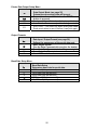
Calibration Menu
CAL
0
Zero Calibration Mode.
Calibration Zero
Press ZERO to perform calibration of the scale zero.
Successful calibration is indicated by "
"
donE
NOTE: The scale will automatically adjust the offset and gain to
compensate for dead load and span. When making these adjustments,
the scale may ask you to repeat zero calibration immediately after
performing a zero calibration or after a span calibration. Successful
calibration is indicated by "
"
donE
CAL
FS
.50
.25
.10
XXXXXX
Span Calibration Mode.
(Does not appear if CAL 0 is not activated.)
Full load calibration.
Half capacity calibration.
Quarter capacity calibration.
1/10th of capacity calibration.
By pressing the optional print push button weight
value can be entered in. (note: XXXXXX will be the
dialed in weight value. This feature is not available
on 7000.)
NOTE: For maximum accuracy, Doran Scales recommends that all
scales be calibrated at full capacity. When location or installation make
it difficult to bring full capacity weights to the scale, calibration with as
little 10% of capacity is possible.
17
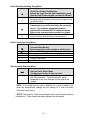
Digital Filter Setup Menu
Avg
A0
A9
A7
A6
A5
A4
A3
C4
C8
C16
C32
C64
Averaging mode
Determines the number of samples to average
Stabil-izer© auto averaging. All readings are
averaged. Display updates 10 times a second.
Stabil-izer© auto averaging. All readings are
averaged. Display updates 9 times a second.
Stabil-izer© auto averaging. All readings are
averaged. Display updates 7 times a second.
Stabil-izer© auto averaging. All readings are
averaged. Display updates 6 times a second.
Stabil-izer© auto averaging. All readings are
averaged. Display updates 5 times a second.
Stabil-izer© auto averaging. All readings are
averaged. Display updates 4 times a second.
Stabil-izer© auto averaging. All readings are
averaged. Display updates 3 times a second.
Fixed averaging 4 readings are averaged.
Display updates 10 times a second.
Fixed averaging 8 readings are averaged.
Display updates 5 times a second.
Fixed averaging 16 readings are averaged.
Display updates 3 times a second.
Fixed averaging 32 readings are averaged.
Display updates 1½ times a second.
Fixed averaging 64 readings are averaged.
Display updates 1 time every 1.4 seconds.
Automatic Zero Tracking Setup Menu
A2t
oFF
0.5
1*
3*
Automatic Zero Tracking Range
Small weights within the specified number of
divisions are automatically zeroed.
Zero tracking is off. No automatic zeroing.
Zero tracking to within 0.5 division.
Zero tracking to within 1.0 division.
Zero tracking to within 3.0 divisions.
* NOTE: The Legal for Trade mode disables some options and selections
listed above. These items have been indicated by an asterisk.
18
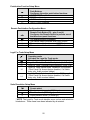
Motion Aperture Setup Menu
nn.A.*
1
3
5
Motion aperture *
Determines how many divisions consecutive
readings must change before the scale is
considered in motion.
1 division change must be seen to enter motion.
3 division change must be seen to enter motion.
5 division change must be seen to enter motion.
Start Up Zero Setup Menu
SU0*
on
CL0
PB0*
Start Up Zero
Controls the start up zero status.
Zeros on the first stable reading on power up.
Loads the calibration zero for zero reference
Loads the last pushbutton zero. (8000XL option only)
Latching Zero Request Setup Menu
2od
on
oFF
Zero on Demand
Enables or disable zero latching.
If ZERO is pressed, it is saved until the scale
becomes stable.
If the scale is in motion, the zero request is
discarded.
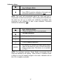
Latching Print Request Setup Menu
Pod
on
oFF
Print on Demand
Enables or disables print latching.
If PRINT is pressed, the print request is saved until
the scale becomes stable.
If the scale is in motion, the print request is
discarded.
* NOTE: The Legal for Trade mode disables some options and selections
listed above. These items have been indicated by an asterisk.
19
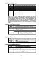
Printer Data Output Setup Menu
d.o.
t.o.d.
C.P.
A.P.1
A.P.2
Data Output Mode (see page 25)
Determines when serial data will be sent.
Transmit on demand. Print when the PRINT
button is pressed.
Continuous Print. Print when display is updated.
Auto Print 1. Print once only when scale goes stable.
Auto Print 2. Print once only when scale goes stable.
Scale must return to zero to before it can print again.
Output Formats
For.
F0
2d
SSP
F9
Data Input / Output Format (see page 26)
Defines the appearance of the serial data sent.
Basic output format.
(See the Data Communication section for details)
Basic Dual Print Format. Includes Kilogram weight.
Basic Output for Eltron printer.
Model 8000 emulation
Baud Rate Setup Menu
br.
12
24
48
96
14.4
Baud Rate Setup
Determines baud rate for serial data.
1200 baud (bits per second)
2400 baud (bits per second)
4800 baud (bits per second)
9600 baud (bits per second)
14,400 baud (bits per second)
20
Serial Data Handshaking Setup Menu
HS
oFF
SF
CtS
Serial Data Output Handshaking
Selects the type of serial data handshaking used.
(See the Data Communication section for details)
No handshaking is used. Data is sent when ready,
receiving device (printer) must be fast enough to keep
up with the data.
Software handshaking. Data is sent when ready.
Transmission can be controlled by the receiving
device. The software handshaking option
activates Bi-directional RS232 communications.
Refer to the communications section for details.
CTS Handshaking. Data is sent only when CTS is
active. Disables bi-directional communications.
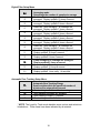
Units Conversion Setup Menu
CSL
CA *
Lgo
Lh
Lo
go
Convert Select Modes
Determines which units selections will be active.
Convert All. lb, kg, g, oz and lb-oz are active.
lb, kg, g and oz are active.
lb and kg are active.
lb and oz are active.
g and oz are active.
Start Up Units Selection Menu
UnitS
Start Up Units Select Mode
Configures selection of start up units.
Press ZERO to scroll through the units activated in
the CSL parameter. The selected units will be
displayed on the units indicators to the right of the
display.
NOTE: If an invalid start up unit is selected for a given capacity, the
scale will automatically change the unit setting to a valid unit when
exiting the setup menu.
* NOTE: The Legal for Trade mode disables some options and selections
listed above. These items have been indicated by an asterisk.
21
Push-button Function Setup Menu
P.b.
CP
P
C
non
Push Buttons
Configures the active push button functions.
UNITS, PRINT enabled
PRINT enabled only.
UNITS enabled only.
UNITS, PRINT disabled.
Remote Push-button Configuration Menu
r.P.b.
OFF
P
C
0
Remote Push Button (P2 – pins 3 and 4)
Configures the Remote Switch to perform one of
the three front panel functions.
The remote switch is disabled.
The remote switch functions as a PRINT button.
The remote switch functions as a UNITS button.
The remote switch functions as a ZERO button.
Legal For Trade Setup Menu
oP *
Std
44
CAn
44S
CnS
Operating mode
Activates the Legal for Trade mode.
Standard operation (Audit Trail)
Legal for Trade, Handbook 44 compliant. (Audit Trail)
Legal for Trade, Canadian W&M compliant. (Audit Trail)
Legal for Trade Switch mode, Handbook 44 compliant.
(Front Panel Cal Access feature disabled, Cal Switch
entry only, Audit counters hidden)
Legal for Trade Switch mode, Canadian W&M compliant.
(Front Panel Cal Access feature disabled, Cal Switch
entry only, Audit counters hidden)
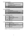
Scale Resolution Setup Menu
CtS
3
P
SP
Counts select
Standard precision mode (3000d typ.)
Precision mode (5000d typ.)
Super precision mode (10,000d typ.)
* NOTE: The Legal for Trade mode disables some options and selections
listed above. These items have been indicated by an asterisk.
22
Unit On Timer (8000XL only)
td4
on
0.5
1
1.5
2
3
5
10
30
Selects the time value that the unit will remain on
Unit will remain on, On timer is off
30 second "On timer"
1 minute "On timer"
1.5 minutes "On timer"
2 minutes "On timer"
3 minutes "On timer"
5 minutes "On timer"
10 minutes "On timer"
30 minutes "On timer"
NOTE: The "On Timer" governs the amount of time the unit stays on
after ON/ZERO is pressed. The electronics in the scale sense activity on
the scale platform - when there is no activity on the platform within the
time programmed for the "On Timer", the unit will turn itself off. Each
time there is activity (motion) on the scale's platform or any pushbutton
activity before the scale turns off, the "On Timer" is reset to its full time
period.
Default all Scale Parameter settings
dEFt
n
4
Default Calibration and Parameter settings.
Do not default settings.
1st yes answer, Default all Calibration and
Parameter settings
Do not default settings
Verify 2nd yes answer, Default all
Calibration and Parameter settings
WARNING: Defaulting the scale will require recalibration.
n
4
Raw Counts Display Mode
Raw
Counts
xxxxxx
Displays the raw Analog to Digital converter
data.
Press UNITS to exit Raw Counts.
Calibration and Parameter Menu Exit
donE
n
4
Exit Calibration and Parameter Menu.
Do not exit menu. Start over at the top of the
parameter list.
Exit Calibration and Parameter menu. Save all
parameter changes. The scale will return to normal
weighing when UNITS is pressed.
23
Data Communications
Introduction to data communications:
In the Model 7000, 7000XL, 8000XL data is sent to a printer or computer by using
"asynchronous serial data communications." Data is broken up and sent one piece at a
time to the printer or computer. In spite of this apparent simplicity, a basic
understanding of serial data communications is needed when setting up the scale.
The scale transmits letters and numbers to a printer or computer by replacing the letter
(or number) with an eight bit ASCII code. This code is then transmitted, one bit at a
time, to a printer or a computer. A bit is the smallest unit of data and can have a value
of "1" or "0." By combining eight bits into a byte, it is possible to get 256 unique bit
patterns. These patterns are used to create the ASCII codes used by the scale to
represent letters and numbers.
When setting up a serial communications system, there are several concerns which
affect the configuration of that system. These are:
transmission rate
knowing when data starts and stops
the ability of the receiving equipment to digest the data sent
The transmission rate determines how fast the data is sent from the scale to the printer
(or computer) and is measured in Baud or bits per second. (For applications such as the
Model 7000, 7000XL, 8000XL, Baud and bits per second are interchangeable.) The
transmission rate controls how many bits can be sent in a given time. It is important
that the sending and receiving units are set to the same Baud settings. Typical values
are 1200, 2400, 4800 and 9600 baud.
The term "asynchronous serial data communications" implies that the sending unit has
no way of telling the receiving unit when a data bit has been sent or when to expect the
next bit. To correct this problem, both the sending and receiving units use the baud rate
setting to determine how fast data should be sent. If the baud rates at the sending and
receiving units differ, the receiving unit will expect data to arrive at a different time than
when the transmitting unit sent it. When this happens, data will be lost. When the baud
rates match, the receiving unit has no problem with the data arriving early or late. The
only problem is knowing when the data transmission started.
The scale and the equipment connected to it resolve this dilemma by sending a "start
bit" at the beginning of each data byte. This bit tells the printer or computer that a new
data byte is on the way. When the start bit is received, the bit timer starts running and
runs until it has received the correct number of bits.
The number of bits sent by the scale is controlled by the data bits, parity and stop bit
configuration. The scale is factory set for eight bits, no parity and one stop bit. This
means that the eight bits following the start bit will be data, followed by a stop bit. The
stop bit signals the end of the data and permits the bit timer a chance to reset itself
before the next data byte is sent. No parity bits are sent.
24
In many cases, the receiving unit is a slow printer with limited memory. In these cases,
more data may be sent than the printer can use. Again, data may become lost or
scrambled. To prevent this from happening, "Handshaking" is used. When the receiving
unit is busy or incapable of receiving further data, it activates the handshaking; telling
the sending unit to stop transmission. Then, whenever the receiving unit is ready for
more data, it deactivates the handshaking and data transmission continues.
The scale offers hardware and software handshaking. Hardware handshaking makes
use of the CTS (clear to send) input on the unit. When this signal is active, the scale is
permitted to send data. When the receiving unit is busy, the CTS line is deactivated
and the scale stops sending data. When the receiving unit is ready for more data, the
CTS is reactivated and the scale will finish sending the data string it was sending when
transmission was interrupted. All readings created while transmission is halted are
discarded.
Software handshaking relies on bi-directional communications to send the XON (Ctrl-Q)
and XOFF (Ctrl-S) flow control characters. The scale has limited bi-directional serial
communications to support software handshaking. When a "Ctrl-S" is received, the
transmission of data is halted until a "Ctrl-Q" is received. To use this mode, the RTX line
of the scale is tied to the TXD line of the receiving unit. Refer to Doran RS-232 Training
Technical Bulletin (MAN0214) for in depth coverage of this subject.
Printer Modes:
The Model 7000, 7000XL, 8000XL offers four different print control modes. These
modes dictate when printer data is sent.
Transmit on demand ( ):
In this mode, scale data is transmitted whenever the print button is pressed, the remote
print button is pressed, or a print request is received from the serial port. The scale must
be stable and the scale value must be valid before the data is printed.
tod
Continuous print ( ):
In continuous print, data is transmitted each time the scale has a reading ready.
Readings which occur when the scale is in motion are called out by the abbreviation
"MOT." following the data.
CP
Auto Print 1 ( ):
Auto Print 1 transmits the first scale reading after the scale leaves motion. The reading
must be stable and must be a valid reading before it can be sent.
AP1
Auto Print 2 ( ):
Like Auto Print 1, Auto Print 2 transmits the first scale reading following the scale
leaving motion. In Auto Print 2, no further readings will be sent until the scale returns to
displayed zero. The reading must be stable and must be a valid reading before it can be
sent.
AP2
25
Data output format:
In order for the serial data sent from the scale to be useful, the data must be organized
so that it is easy to read. To accomplish this, the scale arranges the displayed data with
additional text to indicate the active units and to indicate the presence of motion during
the reading.
" " Format:
The basic data format sent by the scale is illustrated in Table 2. Each line of data
begins with an STX character (start of text) followed by a polarity sign, which
indicates the reading polarity. Next, the displayed data is sent. Six digits are
used with a decimal point inserted in the correct position. After the weight data is
sent, a space followed by the units are added to the string. When motion is
present, another space is inserted followed by "MOT." The string is then finished
by adding a carriage return and a line feed.
F0
In the case of lb-oz data, the pounds value is placed after the polarity sign. A
space followed by "lb" and another space follows the pounds data. Ounce data is
then sent with a decimal point inserted where needed. Once again a space is
inserted after the weight data followed by "oz." Only six digits are sent in the lboz mode so the allocation of these digits depends on the ounces resolution.
Refer to Table 2 for details.
" " Format:
In the "DUAL PRINT" format, the current weight is first printed using the "F0"
format. Then the weight is recalculated in kilograms and is sent as a second line
of text. The kilogram data follows the "F0" data format except where parentheses
are placed after the STX character and before the carriage return, line feed.
Refer to Table 2 for details.
2d
" " format:
The data string produced by the SSP format allows the scale to communicate
with an Eltron Label Printer. This printer allows the creation of custom labels
containing weight information, bar codes and graphics. Refer to Table 2 for
details.
SSP
" " Format:
In the "8000 emulation" format, the print string is the same as the "F0" format.
The only difference is that “grs” message is add between the current units <uu>
and the motion <MOT> status. Refer to Table 2 for details.
Fg
26
Command
(RXD)
Scale output Response (TXD)
Description
W
(hex 57)
<STX><p><xxxx.xx><SP><uu><SP><MOT><CR><LF>
or
<STX><p><xxxx.xx><SP><uu><SP><MOT><CR><LF>
<(><p><xxxx.xx><SP><kg><SP><)><MOT><CR><LF>
or
<FR”L1”><LF><?><LF><p><xxxx.xx><LF><uu><LF>
<GS><LF><MOT><LF><p><xxxx.xx><LF><kg><LF>
<P1,1><LF>
or
<STX><p><xxxx.xx><SP><uu><SP><grs><MOT>
<CR><LF>
“_ ” standard format, Prints current weight
and units.
“_ ” dual print format, Prints current and kg
weight resolution.
F0
2d
“
SSP” Label printer format, for Eltron printers
“_ ” 8000 emulation format, Prints current
weight, units, and “grs”.
Fg
<xxxx.xx> weight data (fixed field of 6 digits
plus decimal or “-------“ for overload,
underload, gross underload, or gross
overload)
<p> polarity “-“ or “ “
<GS> gross or net status (always “GS”)
<uu> current units
<SP> line space (hex 20)
<MOT> motion status (“MOT.” or “ “)
<CR> carriage return (hex 0D) (control-M)
<LF> line feed (hex 0A) (control-J)
Scale changes units
U
(hex 55)
Z
(hex 5A)
XON
(hex 11, ctrl-Q)
XOFF
(hex 13, ctrl-S)
Zeros scale
Turns on serial handshaking
scale output disabled
Turns off serial handshaking
scale output enabled
Table 2: Doran serial protocol
27
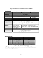
Specifications and Interconnect Data
Specifications:
Model:
Resolution:
Sensitivity:
Load Cell Capacity:
Power Supply:
Display:
Displayed units:
Capacities:
Printer Interface:
Calibration
Controls:
Construction:
Options:
Interconnect Data:
PIN #
1
2
3
4
5
6
7000
7000XL
8000XL
10,000d in precision mode
0.5 uV min.
0.5 mV/V to 3.5 mV/V
115/230VAC 50/60Hz
115/230VAC 50/60Hz
6V Battery
6 digit LED. 0.56" high
lb, kg, oz, g and lb oz
2 to 100,000 lb
Bi-directional RS-232
Unit may be calibrated with 10%, 25%, 50%, or 100% of capacity
Or user selected.
ZERO switches.
Polycarbonate touch panel with built in
Optional UNITS &
ZERO, UNITS, PRINT and Hidden buttons.
PRINT switch.
Rugged Stainless Steel NEMA 4/4X (IP 65) construction.
User configurable remote switch.
6 digit LED remote display
Internal 4-20mA output
Table 3: Scale Specifications
TITLE
WIRE COLOR CODE
+ Load Cell Signal
Red
- Load Cell Signal
White
+ Load Cell Excitation
Green
- Load Cell Excitation
Black
+ Sense Signal
Blue
- Sense Signal
Brown or Orange
Table 4: TB1 Load Cell Connections
NOTE: When connecting the loadcell, be sure to install the ESD and EMI protection
inductor. Refer to Fig. 9 for details.
28
PIN #
1
2
3
4
5
P2 Options Connections
TITLE
WIRE COLOR CODE
RTX
White
TXD
Red
Remote Switch High
White
Remote Switch Ground
Black
RS232 Signal Ground
Black
Table 5: P2 Options Connections
PIN #
1
2
3
4
J1 Power Connections
TITLE
WIRE COLOR CODE
n/c
NA
Neutral
Blue
Ground
Green
Hot
Brown
Table 6: J1 Power Connections
P3 Keyboard Connections
PIN #
TITLE
1
Zero Switch Ground
2
Zero Switch High
3
Units Switch
4
Print Switch
5
Hidden Switch
6
Keyboard Scan
Table 7: P3 Keyboard Connections
WHITE
BLACK
SHRINK
SHIELD
CnS
Fig. 6: Connector J2, Remote switch cable assembly
29
WHITE
RED
GREEN
SHRINK
SHIELD
SHRINK
BLACK
Fig. 7: Connector J2, Serial cable assembly
RS232 Output
DB9 Female connector
Function
Pin
N/A
1
TXD
2
RXD/CTS
3
N/A
4
Signal GND
5
N/A
6
N/A
7
N/A
8
N/A
9
Table 8: Serial Output pin description
Fig. 8: RS232 Output DB9 Connector (optional)
30
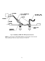
Fig. 9: Installation of EMI / RFI / ESD protection devices.
NOTE: Fig. 9 illustrates a 7000/7000XL/8000XL connected with a 4-wire load cell.
When installing a 6-wire cell, remove shunts at JU7 and JU8.
31
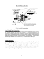
Fig. 10: Jumpers and Connector Locations
Jumper
JU1
JU7
JU8
JU10
JU20
JU21
JU22
Jumper settings per model
7000
7000XL
8000XL
OUT
OUT
IN
In for 4 wire and Out for 6 wire loadcell connections
In for 4 wire and Out for 6 wire loadcell connections
IN
IN
OUT
OUT
IN
OUT
LEFT TWO PINS
RIGHT TWO PINS
RIGHT TWO PINS
LEFT TWO PINS
RIGHT TWO PINS
RIGHT TWO PINS
Table 9: Board Jumper settings
32
4-20mA Analog Output (optional)
Introduction
The 4-20mA Analog Output Option is used to provide an analog output that is
proportional to the weight on the scale platform. Because of the inherent noise immunity
present in a current loop, an isolated 4-20mA analog output is ideal for use in noisy
environments. The 4-20mA analog output option can be used to send weight data to a
process indicator, a simple on/off controller or to a programmable logic controller.
Setup
To setup the 4-20mA Analog Output Option, calibrate unit like a standard scale. This
procedure is found in the instruction manual. The 4-20mA option is automatically
calibrated for an output range of 4mA to 20mA, (i.e. 4mA equals zero weight and 20mA
equals the scale’s capacity). Once the basic scale has been connected and calibrated,
attach the output cable from the appropriate controller or indicator to the 4-20mA option
board. The white lead is connected to the + input of TB2 and the black lead is
connected to the – input of TB2.
Active (default) or Passive mode, if your application requires a self power (Active mode)
analog output, place jumpers on pins 3,4 (ACT) on JU1 and JU2. For loop power
(Passive mode) applications, place jumpers on pins 1,2 (PAS) on JU1 and JU2. See
Fig 11 for jumper locations.
Calibrate your process indicator or controller according to the manufacturer's
instructions. Remember that the option will output 4mA when the scale reads "zero" and
20mA when the scale reads full capacity. NOTE: If the scale is in a fault condition, the
4-20mA output levels are 3.5mA for gross underload or underload, and 24mA for gross
overload or overload. Output impedance range is zero to 600 ohms.
Operation
There is no effect on scale operation when the 4-20mA Analog Output Option is
installed. The only exception to this is on the 8000XL where battery life will be reduced
by 50% when the 4-20mA option is set to the active mode. To increase battery life back
to normal, set option output for passive mode.
Connect serial interface
cable to J4C terminal on
scale’s main board
Connect output
cable to terminal
block TB2
Active /
Passive jumper
settings
Fig. 11: 4-20mA analog option board
33
Troubleshooting
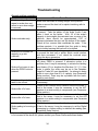
General problem resolution:
Problem:
What to Do or Check:
Weight reading will not
Make sure that there is nothing caught in the platform
repeat or scale does not
under or around the load cell or spider interfering with its
return to zero when weight
movement.
is removed.
Make sure all four corner overload stops are properly set,
if present. Take the platter off the scale, invert it and
place it back on the spider. With 1/2 of the scale's
capacity in test weights concentrated over a corner of the
Scale overloads early.
platform, there should be approximately 1/32" of
clearance between the stop and the bottom of the spider.
Check all four corners then recalibrate the scale. If the
problem persists, it is possible that the scale is being
shock-loaded causing the load cell to be shifted.
Make sure that there is nothing caught in the scale under
Scale will not indicate full
or around the load cell or spider, which would interfere
capacity or go into
with their movement. If not, check the overload stops
overload.
using the above procedure.
Make sure that the scale is stable ("MOT" annunciator is
off) when ZERO is pressed. If excessive motion is a
problem, then it may be necessary to activate the latching
Scale will not come to zero print feature ( ) or lengthen the filter time (
). If the
when the ZERO button is
scale is stable, the scale may be set to the Canadian
pressed.
Legal for Trade (4% zero bandwidth). An attempt is being
made to zero more than 4% of capacity (see Parameter
Setup section). There may be a problem with the touchpanel or main board.
Weight readings don't
Check the scale's accuracy with a test weight. Recalibrate
seem to be correct.
if necessary.
Check for air currents and/or vibration around the scale. If
that is the cause, it may be necessary to set the AZT
Scale drifts off of zero.
aperture to a wider setting to compensate (see Parameter
Setup section).
Check for air currents and/or vibration around the scale. If
that is the cause, it may be necessary to set the AZT
Scale drifts off of zero.
aperture to a wider setting to compensate (see Parameter
Setup section).
Check for air currents and/or vibration around the scale.
Scale reading is bouncing or If that is the cause, it may be necessary to set the Digital
"flighty".
Averaging to a higher setting to stabilize the reading (see
Parameter Setup section).
If you are still experiencing a problem with your scale, or if the problem you are having
is not covered in the above list, please contact your Doran Scales authorized dealer.
POd
34
Avg C32
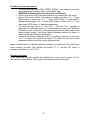
Resetting the scale parameters:
If at some point the Model 7000, 7000XL, 8000XL, user wishes to return the
setup parameters to factory default, follow these steps.
WARNING: Defaulting the scale will require recalibration.
Enter Cal mode by using Cal access feature or by pressing the CAL button.
Once in CAL menu, use the units button to scroll to menu item "
". Press
ZERO button to select yes "
". Press UNITS button to enter answer,
display will show again "
", Press ZERO button to select yes "
" and
then press UNITS button, to default all parameters.
The scale will then show " " and "
". After the "
" message is
displayed the scale then perform its normal power up routine and enter the
Calibration mode. At this time, all the parameters will have been reset to their
factory default settings. See Setup Menus Explained section for details on
setting up the individual scale parameters.
Return to the normal weighing position by scrolling to the end of the menu
"
" or press CAL push button again. The scale will save the revised
parameters and will enter the normal weighing mode.
dEFt n
dEFt 4
dEFt 4
dEFt n
InIt
SAVEd
SAVEd
donE 4
Note: A second method to default parameter settings is by holding the CAL push button
while powering up scale. The indicator will display "
" until the CAL button is
released, then show " " and "
".
rEL Pb
InIt
SAVEd
Resetting the scale:
In the event that a power problem has disabled the scale, remove power, wait 15
seconds and restore power. The scale should restart and function properly.
35
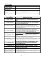
Scale Messages:
Message
"
"
Function complete.
"
"
Aborted function.
"
"
Parameter value saved.
"
"
Release push button.
donE
Abort
SAVEd
rEL Pb
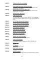
Error messages:
Error Message
"
ovr Ld" Scale overload
"
udr Ld" Scale underload
"
grS oL" Gross overload
"
grS uL" Gross underload
"
SU 0 E" Startup zero error
"Er Ad" A/D failure
"
Err EP" EEPROM error
"
Err CAL" Calibration error
"
"
Err 1" Program ROM error
Ldg 0" Loading zero.
“SPAn E”
Calibration Range Error
“rA Err”
Calibration Span Error
Meaning
The scale has successfully completed the requested action.
The requested action has been canceled prior to completion.
The scale has successfully store and verified parameter
value in nonvolatile memory.
The scale has detected that a key has been depressed for
more than 3 seconds.
What to Do or Check:
The scale is in overload. The load on the scale exceeds the
capacity by more than 103%. Remove excess weight from
scale.
The scale is in underload. The load on the scale is less then
the minimum scale capacity by more than -20%. Recalibrate
scale or add additional dead load.
The scale is in gross overload. The load exceeds the scale
ratings and might result in damage to the scale. Remove
excess weight immediately. Ignore this message for the first 5
seconds after power up.
The scale is in gross underload. The load exceeds the
minimum scale ratings and might result in damage to the
scale. Loadcell connections might be wired in reverse. Ignore
this message for the first five seconds after power up.
The scale was not stable. This error will only occur in Legal for
Trade applications. The scale will zero once it becomes
stable.
The scale has detected a failure in A/D circuit. Have scale
serviced by a qualified scale repair technician.
The setup parameters loaded in nonvolatile memory have
become corrupted. The scale requires recalibration by a
qualified scale technician.
The calibration values loaded in nonvolatile memory have
become corrupted. The scale requires recalibration by a
qualified scale technician.
The program memory in the scale has become corrupted.
Have scale serviced by a qualified scale repair technician.
The scale is attempting to load power up zero. This message
will remain until scale is stable.
Calibration zero is out of range, refer to A/D Ranging section
for additional information.
Calibration Span is out of range, refer to A/D Ranging section
for additional information.
36
Replacement Part List
SUB0408
7000/7000XL Main PCB Assembly, 115 VAC
SUB0408-1
7000/7000XL Main PCB Assembly, 230 VAC
PCA0223
8000XL Main PCB Assembly, 115 VAC
PCA0223D
8000XL Main PCB Assembly, 230 VAC
SUB0013D
7000 Zero Switch Assembly
Pushbutton switch with cable, S/S boot, & PCB connector
SUB0013-1
7000 Zero Switch Assembly 3 Pack
1 set of 3 P/N SUB0013D with S/S Boot
SUB0013C
7000 Zero/Convert Switch Assembly
2 pushbutton switches with cables,
S/S boots, convert label & connectors
SWI0007
7000 Rubber Pushbutton Boot
SWI0048
7000 Stainless Steel Pushbutton Boot
SUB0427
7000XLTouch Panel Assembly
Includes overlay, switch assembly, and installation instructions
SUB0439
7000XL Face Plate Only
Includes face plate and instructions
SUB0395
8000XLTouch Panel Assembly
Includes overlay, switch assembly, and installation instructions
SUB0396
8000XL Face Plate Only
Includes face plate and instructions
SWI0104-B
7000XL/8000XL Inner Switch Assembly
SHP0099
Lens Replacement Glue
Touch panel adhesive.
SUB0004-1
Foot Assembly Set
Rubber feet; S/S 10-24 x 1 screw, sold in sets of 6 only
HDW0042
S/S Foot
Sold singly, for 18"x18" & larger bases, 1/2-20 NF Thread
37
SUB0063-1
Power Cord
Shielded, 8 ft long, 18/3 SJEOW, with chosorb, connector,
assembly, and instruction sheet.
CNT0019
Liquid-Tite Feed Thru
For load cell, power cord & option inputs
SUB0399
Sealing Plug Kit
CNT0256
Load Cell Connector/Plug
LED0046
70000/7000XL LED, Numeric
One red 7 segment display
LED0023
8000XL LED, Numeric
One red 7 segment display
LED0042
7000 LED, Units Indicator
One red LED
LED0003
7000XL LED, Units Indicator
One red 4 segment LED
LED0016
8000XL LED, Units Indicator
One red 4 segment LED
LBL0173-A
Capacity Labels
FUS0019
Fuse, 1/4 Amp, Slo-Blo 7000/7000XL(115VAC), 8000XL(230VAC)
Used in P/N SUB0408, PCA0223D
FUS0020
Fuse, 1/2 Amp, Slo-Blo 8000XL(115VAC)
Used in P/N PCA0223
FUS0021
Fuse, 1/18 Amp, Slo-Blo 7000/7000XL(230VAC)
Used in P/N SUB0408-1
SUB0038-4
8000XL Battery
4 Ah, 6 Volt, lead acid, rechargeable, with terminals, and wires
ENC0585
8000XL Battery Bracket
SUB0365
7000 Lens Replacement Kit
Clear lens, red lens, and RTV adhesive
XFR0027
7000/7000XL Power Transformer, 115/230 VAC
XFR0029
8000XL Power Transformer, 115/230 VAC
38
SUB0235
Calibration Port Cover Assembly
Includes cover, gasket & screws
SUB0438
7000/7000XLGasket & Screw Set, Rear Panel
3 standard, 1 cross-drilled 10-32 bolts, 4 rubber bonded metal
washers and 1 rear gasket.
8000XLGasket & Screw Set, Rear Panel
3 standard, 1 cross-drilled 10-32 bolts, 4 rubber bonded metal
washers and 1 rear gasket.
SUB0398
GSK0024
Rubber Gasket, Rear Panel
SUB0455
E Mounting BracketsConnects Base to Indicator, same as Option E. If the scale base
does have drilled and tapped holes on the side, this part MUST be
used.
SUB0417
Kit, 14” Atlas Column with Hardware
SUB0425
Kit, 20” Atlas Column with Hardware
SUB0426
Kit, 30” Atlas Column with Hardware
MAN0159
7000 Operator User Manual
MAN0192
7000X Operator User Manual
MAN0191
8000XL Operator User Manual
SUB0440
7000 Case Cover Assembly
With lens & zero S/S push button
(Specify Capacity)
SUB0441
7000XL Case Cover Assembly
With touch panel (backplate not included)
SUB0397
Case Cover Assembly
Touch panel included (Includes both SWI104-B & SWI105)
HDW0011
Bubble Level
ENC0624
"U" Bracket
Tilt Stand bracket for case
ENC0604
7000/7000XL Backplate
Rear cover
ENC0586
8000XL Backplate
Rear cover with cord wrap bracket (w/o battery bracket or battery)
39
SUB0210-1
Knob, "U" Bracket Adjust
Adjustment knob with washer
SUB0041-1
Foot Switch
Non wash down, cable included
70/70XL-042-C
RS-232 Data Cable
Pigtail end.
70/70XL-042-C1
RS-232 Data Cable
With Female DB9 Connector
70/70XL-042-C2
RS-232 Data Cable
With Female DB25 Connector
SUB0442
Calibration/Units Switch Replacement Kit
Includes switches and caps
IND0006
Power Cord Chosorb
MSC0085
7000/7000XL Scale Veil
MSC0102
8000XL Scale Veil
70OPTX
7000 Analog 4-20mA Output
7XOPTX
7000XL Analog 4-20mA Output
8XOPTX
8000XL Analog 4-20mA Output (Passive only)
30OPT36
6-digit Remote Display
40
Warranty Statement
41