1
Horner Electric's
Operator Interface Unit
for the
GE Fanuc GENIUSTM Network
User's Manual, for
HE693OIU900
Horner Electric Advanced Products Group
GENIUS is a trademark of GE Fanuc Automation, North America, Inc.
12-10-97
MAN0191-03
FOR NORTH AMERICA ONLY!
MODEL NUMBER: HE693OIU900
SERIAL NUMBER:
WARRANTY REGISTRATION FORM
Please fill out this form and return it to Horner Electric. This information is vital to Horner Electric,
should warranty service be required. This document is also used to keep you informed of new
product enhancements, software revisions and documentation updates.
IT IS IN YOUR BEST INTEREST TO FILL OUT AND RETURN THIS FORM!
Date of purchase:
Name:
Title:
Company:
Department/Division:
Street Address:
City/State/Zip:
Area Code/Phone Number:
Purchased from (Distributor):
Please indicate the type of application where this product is to be used, check all that apply:
Chemical processing
Demo equipment
Education
Energy management
Food processing
Military
Product assembly/testing
Waste processing
Other (specify)
product:
FOLD
STAMP
Horner Electric, Inc.
APG - Controls Division
1521 East Washington Street
Indianapolis, Indiana 46201-3899
ATTN: Warranty Registration Department
FOLD
PREFACE
Page iv
PREFACE
This manual explains how to use the Horner Electric Operator Interface Unit for use with the GE
Fanuc Genius I/O Network.
Copyright (C) 1991,1992 Horner Electric, Inc., 1521 East Washington Street, Indianapolis Indiana
46201-3899. All rights reserved. No part of this publication may be reproduced, transmitted,
transcribed, stored in a retrieval system, or translated into any language or computer language,
in any form by any means, electronic, mechanical, magnetic, optical, chemical, manual or
otherwise, without the prior agreement and written permission of Horner Electric, Inc.
Information in this document is subject to change without notice and does not represent a
commitment on the part of Horner Electric, Inc.
Genius, Logicmaster and Series 90 are trademarks of GE Fanuc Automation North America Inc.
Third Edition
Page v
PREFACE
LIMITED WARRANTY AND LIMITATION OF LIABILITY
Horner Electric, Inc. ("HE") warrants to the original purchaser that the Operator Interface Unit
manufactured by HE is free from defects in material and workmanship under normal use and
service. The obligation of HE under this warranty shall be limited to the repair or exchange of any
part or parts which may prove defective under normal use and service within two years from the
date of manufacture or eighteen (18) months from the date of installation by the original purchaser
whichever occurs first, such defect to be disclosed to the satisfaction of HE after examination by
HE of the allegedly defective part or parts. THIS WARRANTY IS EXPRESSLY IN LIEU OF ALL
OTHER WARRANTIES EXPRESSED OR IMPLIED INCLUDING THE WARRANTIES OF
MERCHANTABILITY AND FITNESS FOR USE AND OF ALL OTHER OBLIGATIONS OR
LIABILITIES AND HE NEITHER ASSUMES, NOR AUTHORIZES ANY OTHER PERSON TO
ASSUME FOR HE, ANY OTHER LIABILITY IN CONNECTION WITH THE SALE OF THIS
OPERATOR INTERFACE UNIT. THIS WARRANTY SHALL NOT APPLY TO THIS OPERATOR
INTERFACE UNIT OR ANY PART THEREOF WHICH HAS BEEN SUBJECT TO ACCIDENT,
NEGLIGENCE, ALTERATION, ABUSE, OR MISUSE. HE MAKES NO WARRANTY WHATSOEVER IN RESPECT TO ACCESSORIES OR PARTS NOT SUPPLIED BY HE. THE TERM
"ORIGINAL PURCHASER", AS USED IN THIS WARRANTY, SHALL BE DEEMED TO MEAN
THAT PERSON FOR WHOM THE OPERATOR INTERFACE UNIT IS ORIGINALLY INSTALLED.
THIS WARRANTY SHALL APPLY ONLY WITHIN THE BOUNDARIES OF THE CONTINENTAL
UNITED STATES.
In no event, whether as a result of breach of contract, warranty, tort (including negligence) or
otherwise, shall HE or its suppliers be liable of any special, consequential, incidental or penal
damages including, but not limited to, loss of profit or revenues, loss of use of the products or any
associated equipment, damage to associated equipment, cost of capital, cost of substitute
products, facilities, services or replacement power, down time costs, or claims of original
purchaser's customers for such damages.
To obtain warranty service, return the product to your distributor after obtaining a "Return Material
Authorization". Include a description of the problem, proof of purchase, post paid, insured and in
a suitable package.
PREFACE
Page vi
ABOUT THE PROGRAM EXAMPLES
The example programs and program segments in this manual are included solely for illustrative
purposes. Due to the many variables and requirements associated with any particular installation,
Horner Electric cannot assume responsibility or liablity for actual use based on the examples and
diagrams. It is the sole responsibility of the system designer utilizing this software to appropriately
design the end system, to appropriately integrate the Operator Interface Unit and to make safety
provisions for the end equipment as is usual and customary in industrial applications as defined
in any codes or standards which apply.
Page vii
PREFACE
TABLE OF CONTENTS
CHAPTER 1: INTRODUCTION .
1.1
1.2
1.3
1.4
.
.
.
.
.
Page 1-1
.
.
.
.
.
.
.
.
.
.
.
.
.
.
.
.
Page 1-1
Page 1-1
Page 1-2
Page 1-2
.
.
.
.
.
.
.
.
.
.
.
.
.
.
.
.
.
.
.
.
.
.
.
.
.
.
.
.
Page 2-1
Page 2-1
Page 2-2
Page 2-2
Page 2-3
Page 2-5
Page 2-5
.
.
.
.
Page 3-1
System RAM Memory Test .
Keypad / Display Test
.
Genius I/O Test
.
.
RS232 Port Loopback Test .
Display Brightness Test
.
LED Test
.
.
.
Watchdog Reset Test
.
.
.
.
.
.
.
.
.
.
.
.
.
.
.
.
.
.
.
.
.
.
Page 3-2
Page 3-2
Page 3-2
Page 3-2
Page 3-2
Page 3-2
Page 3-3
What You Have
.
.
Operator Interface Unit Features
Hardware Description
.
Specifications
.
.
CHAPTER 2: INSTALLATION
2.1
2.2
2.3
2.4
2.5
2.6
2.7
Mounting Requirements
.
Power Requirements
.
Genius Network Connector .
RS232 Connector .
.
GENI Configuration .
.
OIU DIP Switches .
.
Logicmaster 90-70 Configuration
CHAPTER 3: INITIAL OPERATION
3.1
Running the Self Test
3.1.1
3.1.2
3.1.3
3.1.4
3.1.5
3.1.6
3.1.7
3.2
Operating Modes
.
.
.
.
.
.
.
Page 3-3
3.2.1 Set-up Mode .
3.2.2 Autorun Mode
.
.
.
.
.
.
.
.
.
.
Page 3-3
Page 3-3
.
.
.
.
.
Page 4-3
.
.
.
.
.
.
.
.
.
Page 4-4
.
Page 4-6
.
Page 4-11
CHAPTER 4: THE MAIN MENU
4.1
Define Display
.
4.1.1 Text Character Entry .
4.1.2 Defining I/O Data Fields
4.1.3 Copying Screens
.
PREFACE
Page viii
CHAPTER 4: THE MAIN MENU
4.2
4.3
4.4
4.5
4.6
4.7
4.8
4.9
4.10
Define Text Table .
Define Function Key .
High User Screen Number
Set Passwords
.
Set LED Register .
Set Trigger Register .
Enter AUTORUN Mode
Serial Port Set-up .
Self Test
.
.
.
.
.
.
.
.
.
.
.
.
.
.
.
.
.
.
.
.
.
.
.
.
.
.
.
.
.
.
.
.
.
.
.
.
.
.
.
.
.
.
.
.
.
.
.
Page 4-11
Page 4-13
Page 4-16
Page 4-17
Page 4-17
Page 4-18
Page 4-18
Page 4-18
Page 4-19
Changing Screens .
.
.
Monitoring Genius Network Data .
Changing Genius Network Data .
.
.
.
.
.
.
.
.
.
Page 5-1
Page 5-1
Page 5-2
5.3.1 Forced Genius I/O .
5.3.2 Releasing Forced I/O
.
.
.
.
.
.
.
.
Page 5-4
Page 5-4
Exiting AUTORUN Mode
.
.
.
.
Page 5-4
.
.
.
.
.
.
.
.
.
.
.
.
.
.
.
.
.
.
.
.
.
.
.
.
Page 6-1
Page 6-2
Page 6-2
Page 6-2
Page 6-2
Page 6-3
Page 6-5
Page 6-6
CHAPTER 5: AUTORUN MODE
5.1
5.2
5.3
5.4
.
CHAPTER 6: GENIUS DATA TYPES
6.1
6.2
6.3
6.4
6.5
6.6
6.7
6.8
90-70 Data .
.
.
.
Discrete Block I/O Data (BIO)
.
Block Analog Input Data (BAI)
.
Block Analog Output Data (BAQ) .
PowerTRAC Block Data (PWR) .
High-Speed Counter Block Data (HSC)
Genius Block Configuration Data (CFG)
Genius Block Diagnostic Fault (FLT)
APPENDIX A:
PROGRAMMING/PRINTING PORT
APPENDIX B:
PANEL CUTOUT
APPENDIX C:
DISPLAYABLE CHARACTERS
Page ix
PREFACE
This Page Intentionally Left Blank
CHAPTER 1: INTRODUCTION
Page 1-1
CHAPTER 1: INTRODUCTION
Congratulations on your purchase of the Horner Electric Operator Interface Unit! This module
has been designed using state-of-the-art electronic components and incorporates a sophisticated firmware package that gives the Original Equipment Manufacturer (OEM) the ability ot
customize the module for virtually any application.
1.1
What You Have
The Horner Electric Operator Interface Unit (OIU) comes complete with the following items:
1.2
A.
Assembled OIU module and mounting hardware, including the
GeniusTM Network Interface board (GENI).
B.
Optional back panel shroud.
C.
Optional IBM/PC configuration kit.
D.
This manual.
Operator Interface Unit Features
The Horner Operator Interface Unit provides the following features:
A.
Large, 2 line by 20 character dot-matrix vacuum-fluorescent display, brightness is adjustable via the keypad.
B.
32 position metal dome tactile feel keypad with full numeric support
.
C.
12 function keys, each can be programmed with two separate user programmable sequences.
D.
12 user-programmable LED’s that can be configured to reflect the state of
references on the network.
E.
Up to 250 “custom” display screens can be defined by the OEM, each
screen can contain descriptive text and up to four items of data to be read/
written from/to devices on the Genius network.
Page 1-2
CHAPTER 1:
INTRODUCTION
F.
Integrated Genius Network Interface board (GENI), allows access to all
Genius data on the network (discrete I/O blocks, analog I/O blocks,
PowerTRAC blocks, high-speed counter blocks and Series 90-70 register
data).
G.
9-pin RS232 communications port, used by the IBM/PC configuration utility.
H.
Gasketed NEMA 4-12 panel with Lexan overlay, mounting hardware included.
I.
When configured in AUTORUN mode, configuration options can be password protected, and users can be “locked out” of selected screens.
J.
A “trigger” register allows an “intelligent” Genius block to force display of any
of the 250 custom screens.
1.3
Hardware Description
The Operator Interface Unit is a microprocessor-based high-performance communications
device. The core of the module is the Intel 80C152 microprocessor running at 11.0592
MegaHertz. The “firmware” memory is contained in a 27C512 EPROM device. The module is
also equipped with 32K bytes of high-speed static RAM memory, as well as 32K bytes of nonvolatile memory (EEPROM or Flash EPROM). Data retention is specified to be greater than
100 years. There is no battery-backed memory on the module. The OIU module incorporates
a Genius Network Interface board (GENI) that provides the link to the Genius network. The OIU
power supply accepts a wide AC input range.
1.4
Specifications
Mounting Requirements:
Panel Mounting, NEMA 4-12
Communications:
Genius Network Interface (GENI)
Additional Communications:
RS232 for remote configuration.
Power Requirements:
90-240 VAC, 50-60 Hz, 1 Amp (max)
Operating Environment:
0 to 60° C. (32 to 140° F).
0 to 95% humidity (non-condesing).
EEPROM
Flash EPROM
Non-Volatile Memory:
Device Number
Data Retention:
Number of write cycles:
X28C256
100 yrs.
10,000
AT29C256
100 yrs.
1,000
CHAPTER
2:INSTALLATION
Page 2-1
CHAPTER 2: INSTALLATION
2.1
Mounting Requirements
The OIU module is designed for permanent panel mounting. To install the OIU module:
A.
Cut the host panel as described by the drawing in Appendix B.
B.
If the rear panel shroud option is installed, remove the shroud by removing
the five #6-32 screws on the extreme rear of the OIU module.
C.
Remove the six #6-32 hex nuts and washers from the outer mounting studs
on the rear of the OIU panel.
D.
Insert the OIU module through the front panel cutout (be VERY careful not to
pinch or stress the keypad cable). The gasket material should lie between
the host panel and the OIU panel.
E.
Install the six #6-32 nuts and lock-washers on the six mounting studs of the
OIU. Tighten these nuts until the gasket material forms a tight seal, do not
overtighten.
F.
If the rear panel shroud option is present, install the shroud over the mounting standoffs and secure with the five #6-32 screws included. This completes
the mechanical installation of the OIU module.
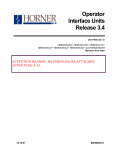
2.2 Power Requirements
The OIU module requires an AC supply voltage between 90 and 240 volts, 50 to 60 Hertz. A
maximum of 1 amp will be drawn by the OIU module. The OIU module is supplied with an AC
mating connector and insertable pins. See figure 2-1 for connector location. The pinout for
this connector is as follows:
Pin
Signal
1
AC Hot
3
AC Neutral
LUG
Earth Ground
Table 2-1. AC connector pinout
Page 2-2
CHAPTER 2:
INSTALLATION
RS-232 Connector
DB-9S
Genius Bus
Connector
AC Power
Connector
(on lower
board)
Figure 2-1. Connectors
2.3
Genius Network Connector
The OIU is also equipped with a 4-pin Genius bus connector. The mating connector provides
screw terminals for each circuit. The pinout for this connector is as follows:
Pin
Signal
1
Serial 1
2
Serial 2
3
Shield Out
4
Shield In
Table 2-2. Genius Network Connector Pinout
2.4
RS232 Connector
The 9-pin “D” connector provides the RS232 interface to an IBM PC/XT or AT computer.
Using the optional “host programming kit”, the OIU module configuration can be created,
stored on disk, and downloaded to the OIU. See Appendix C for cable diagrams for commonly used computers. The pinout for this connector is shown in Table 2-3.
CHAPTER
2:INSTALLATION
Page 2-3
Pin
Signal
1
DCD
2
TXD
3
RXD
4
DTR
5
GND
6
DSR
7
CTS
8
RTS
9
RI
Table 2-3. RS232 Connector Pinout
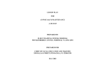
2.5
GENI configuration
The GENI board (located on the rear of the OIU module) is equipped with a bank of 8 “DIP”
switches. DO NOT CONFUSE THIS DIP SWITCH WITH THE 6-POSITION DIP SWITCH ON
THE MAIN CIRCUIT BOARD DESCRIBED LATER. These switches are used to configure the
Genuis “bus” address or “Device Number” for the OIU module, and to set the module’s Genius
baud rate.
Each device on the Genius network must have a unique “Device Number” (0 to 31). The OIU
may be configured for any device number, however the following conventions should be followed when chosing the device number for the OIU:
A.
B.
30.
C.
The bus controller is usually configured as device number 31.
The redundant bus controller (if any) is usually configured as device number
The Hand-Held monitor is usually configured as device number 0.
When shipped from the factory, the OIU dip switches are configured for device number 29, and
for communication baud rate of 153.6K standard. Multiple OIUs may reside on the network,
provided that they have unique device numbers.
Page 2-4
8
CHAPTER 2: INSTALLATION
7
6
5
4
3
2
1
5
4
3
2
1
address
5
4
3
2
1
address
CLOSD
CLOSD
CLOSD
CLOSD
CLOSD
0
OPEN
CLOSD
CLOSD
CLOSD
CLOSD
16
CLOSD
CLOSD
CLOSD
CLOSD
OPEN
1
OPEN
CLOSD
CLOSD
CLOSD
OPEN
17
CLOSD
CLOSD
CLOSD
OPEN
CLOSD
2
OPEN
CLOSD
CLOSD
OPEN
CLOSD
18
CLOSD
CLOSD
CLOSD
OPEN
OPEN
3
OPEN
CLOSD
CLOSD
OPEN
OPEN
19
CLOSD
CLOSD
OPEN
CLOSD
CLOSD
4
OPEN
CLOSD
OPEN
CLOSD
CLOSD
20
CLOSD
CLOSD
OPEN
CLOSD
OPEN
5
OPEN
CLOSD
OPEN
CLOSD
OPEN
21
CLOSD
CLOSD
OPEN
OPEN
CLOSD
6
OPEN
CLOSD
OPEN
OPEN
CLOSD
22
CLOSD
CLOSD
OPEN
OPEN
OPEN
7
OPEN
CLOSD
OPEN
OPEN
OPEN
23
CLOSD
OPEN
CLOSD
CLOSD
CLOSD
8
OPEN
OPEN
CLOSD
CLOSD
CLOSD
24
CLOSD
OPEN
CLOSD
CLOSD
OPEN
9
OPEN
OPEN
CLOSD
CLOSD
OPEN
25
CLOSD
OPEN
CLOSD
OPEN
CLOSD
10
OPEN
OPEN
CLOSD
OPEN
CLOSD
26
CLOSD
OPEN
CLOSD
OPEN
OPEN
11
OPEN
OPEN
CLOSD
OPEN
OPEN
27
CLOSD
OPEN
OPEN
CLOSD
CLOSD
12
OPEN
OPEN
OPEN
CLOSD
CLOSD
28
CLOSD
OPEN
OPEN
CLOSD
OPEN
13
OPEN
OPEN
OPEN
CLOSD
OPEN
29
CLOSD
OPEN
OPEN
OPEN
CLOSD
14
OPEN
OPEN
OPEN
OPEN
CLOSD
30
CLOSD
OPEN
OPEN
OPEN
OPEN
15
OPEN
OPEN
OPEN
OPEN
OPEN
31
7
6
baud rate
CLOSD
CLOSD
153.6K extended
CLOSD
OPEN
38.4K
OPEN
CLOSD
76.8K
OPEN
OPEN
153.6K standard
ALWAYS OPEN
Figure 2-2. GENI DIP Switch Assignments
CHAPTER 2: INSTALLATION
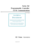
2.6
Page 2-5
OIU DIP Switches
The MAIN circuit board is equipped with a bank of 6 “DIP” switches. These switches are
accessable by removal of the optional rear panel shroud. These switches are used to configure the following OIU options:
6
5
4
3
2
1
NV-RAM Enable (CLOSED=enable, OPEN=protect)
Always CLOSED
NV-RAM (CLOSED=Flash EPROM, OPEN=EEPROM)
Firmware Size (CLOSED=64K, OPEN=32K)
Watchdog Enable (CLOSED=enable, OPEN=disable)
Factory Configured
Figure 2-3. MAIN board DIP Switch Assignments
Except for switch number 1, the user should not change the default settings. The OIU configuration cannot be modified while switch number 1 is set to the ON position.
2.7
Logicmaster 90-70 Configuration
In addition to the hardware setup (on the Geni dip switches) for baud rate and drop number,
the 90-70 be configured to accept global data from the OIU900. This configuration is accomplished via the Logicmaster 90-70 configuration package.
The procedure for configuration of the 90-70 for communications with the OIU900 through
Genius follows on the next page.
Page 2-6
CHAPTER 2: INSTALLATION
Logicmaster 90-70 Configuration Procedure
1)
Invoke the Logicmaster 90-70 Configuration Package.
2)
Select I/O Configuration (<F1>).
3)
Cursor over to the slot containing the Genius Bus Controller to which the
OIU900 is connected.
4)
Press Zoom (<F10>).
5)
Cursor over to the genius bus address of the OIU900. Press Other (<F7>).
6)
A listing of available Genius blocks will be displayed. Select "Geni Based
Device" by pressing <ENTER> (It is the first device listed and is highlighted
by default).
7)
A list of parameters will be displayed. The only one listed will be "Config
Mode". The default is none. Cursor down to this parameter and type
"manual".
8)
Two more parameters will now be displayed. The first of which is "To:", this
represents the 90-70 register address in which Genius data is written from
the OIU to the 90-70. There is only one register of global data written by the
OIU, and that is "current screen number (0-249)". Type in an available %R
address.
9)
The second of the additional parameters is "Input Length". This should be
set to the default value of 1.
10)
Logicmaster configuration for the OIU900 is now complete.
CHAPTER 3:INITIAL OPERATION
Page 3-1
CHAPTER 3: INITIAL OPERATION
This chapter assumes that the OIU module has been mounted and that the power cable has
been properly connected. Power can now be applied to the OIU and (although not necessary
for configuration) the Genius network connection can be made. The following sign-on message will appear:
HORNER GENIUS OIU
HE693OIU900
Vx.yz
This message will remain on the display for approximately 3 seconds. After the sign-on message has been displayed for 3 seconds, the first two lines of the “MAIN MENU” will be displayed on the display;
>Define Display
Define Text Table
3.1
Running the Self Test
At this point, the module is in a mode whereby the operator may select a MAIN MENU item.
Navigation through the OIU module’s menu system is discussed in detail later in this manual,
however the SELF TEST should be executed during the initial operation in order to verify that
the OIU module is properly connected and fully functional. To do this, press the “UP” arrow key
once. The display will “scroll” down to reveal the “Self Test” menu item. The menu pointer will
appear next to this selection. Now press the ENTER key and the self test will commence. The
following tests will be performed.
1.
2.
3.
4.
5.
6.
7.
System RAM Memory Test
Keypad / Display Test
GENIUS I/O Test
RS232 Port Loopback Test
Display Brightness Test
LED Test
Watchdog Reset Test
Page 3-2
CHAPTER 3:
INITIAL OPERATION
3.1.1 System RAM Memory Test
The system memory test will display the amount of memory (in “K” bytes) present. This value
should be 32K bytes. If a value other than 32K is displayed following the completion of the
RAM test, a serious hardware problem exists.
3.1.2
Keypad / Display Test
When the keypad/display test is running the message “Press a key...” is displayed. Each time
the user presses a key on the keypad, the key’s value is displayed. If a key is pressed and it’s
value is not displayed on the display, a keypad problem exists. the keypad test is terminated
by pressing the “SHIFT” and “ENTER” keys simultaneously,
3.1.3 Genius I/O Test
This test simply checks the status of the Genius Network Interface board. If the GENI board
status is OK, this test will pass. If this test fails, consult the factory.
3.1.4 RS232 Port Loopback Test
This test requires the installation of a “loopback” connector on the 9-pin RS232 connector.
This connector simply shorts pin 2 to pin 3, and pin 7 to pin 8. If no loopback connector is
available, simply press the ENTER key to skip the RS232 test and continue. If the loopback
connector is installed, the OIU module will send data out the RS232 TXD line, and the data will
return to the OIU module on the RXD line (through the loopback connector). Two values are
displayed on the OIU’s display: the first value represents the number of characters sent out the
transmitter and the second value represents the number of ERRORS in reception of the data.
3.1.5 Display Brightness Test
The vacuum fluorescent display is capable of displaying data at 4 different brightness levels.
This test allows testing of that circuitry. During execution of this test, simply press the UP or
DOWN arrow keys to increase/decrease the display’s brightness level. Press the ENTER key
when all levels have been tested. Note that the level selected when the ENTER key is pressed
will remain active (even through power failure) until changed by an operator.
3.1.6
LED Test
During this test, the 12 LEDs are simply energized in sequence. When all LEDs have been
verified, press the ENTER key to continue to the next test.
CHAPTER 3:INITIAL OPERATION
3.1.7 Watchdog Reset Test
Page 3-3
This test will test the “watchdog” reset circuitry. After a delay of approximatly 2 seconds, the
module should behave as though the power had just been applied. If the module “locks up”
check the state of the watchdog enable switch (described in the previous chapter).
3.2
Operating Modes
The OIU module operates in two modes: SETUP and AUTORUN mode. When shipped from
the factory, the module will enter the SETUP mode when powered up. The module can be
customized and configured while in SETUP mode and then placed in AUTORUN mode. Both
modes are breifly discussed below.
3.2.1 Set-up Mode
SETUP mode is designed for use by the OEM for configuration and customization of the OIU
module. When in SETUP mode, the OEM can configure the module’s 250 custom “screens”,
define sequences for the function keys, configure the RS232 serial port and perform other OIU
configuration operations. All of these configuration functions can be accomplished either from
the keypad directly, or using the Horner Electric OIU Host Programming Package,
HE600IBMOIU-900. If the OIU is to be configured using the offline personal computer program, the OIU must be in set-up mode to accept the configuration download. After the configuration is complete, the OIU module can be placed in the AUTORUN mode, and the module
will remain in AUTORUN mode (even through power failures) until placed back into SETUP
mode. An optional password can be configured to prevent unauthorized access to SETUP
mode once the module has been placed in AUTORUN mode.
3.2.2 Autorun Mode
AUTORUN mode is designed for use by the OEM’s end customer. Once the module has been
placed into the AUTORUN mode, only the 250 custom “screens” (or a subset of them) are
available to the user. Once the OIU module has been placed into the AUTORUN mode, it will
remain in that mode (even through power failures) until manually placed into the SETUP mode.
An optional password can be configured to prevent unauthorized access to SETUP mode
once the module has been placed in AUTORUN mode.
These modes are discussed in detail in the following chapters.
Page 4-1
CHAPTER 4: THE MAIN MENU
CHAPTER 4: THE MAIN MENU
When shipped from the factory, the OIU module will display the sign-on message for approximately 3 seconds following power-up, followed by the display of the MAIN MENU. The MAIN
MENU consists of 10 items;
Define Display
Define Text Table
Define Function Key
High User Screen #
Set Passwords
Set LED Register
Set Trigger Reg
Enter AUTORUN Mode
Serial Port Set-up
Self Test
Since the vacuum fluorescent display only provides two lines, only two of the menu items will
be displayed at a time. A flashing “pointer” is displayed in the leftmost display column
to designate which menu item is currently “active”. The menu pointer is positioned using the
UP and DOWN arrow keys on the front panel keypad. If the pointer is on the bottom line of the
display and the DOWN arrow key is pressed, the display will “scroll” to reveal the next menu
item and the pointer will point to the newly displayed selection. When the end of the menu is
reached, the menu will start over from the beginning.
Display
Key(s)
Comments
>Define Display
Define Text Table
When the first two lines are
displayed, the pointer is moved
down.
Define Display
>Define Text Table
The down pointer key will
continue to move the pointer.
Define Text Table
>Define Function Key
Display
Key(s)
Comments
CHAPTER 4:THE MAIN MENU
Define Function Key
>High User Screen #
Page 4-2
Each press of the down arrow
button reveals another menu
item...
High User Screen #
>Set Password
Set Password
>Set LED Register
Set LED Register
>Set Trigger Reg
Set Trigger Reg
>Enter AUTORUN Mode
Enter AUTORUN Mode
>Serial Port Set-up
Serial Port Set-up
>Self Test
...until the menu "wraps
Self Test
around" to the first item.
When
the menu
pointer has been moved to the desired menu item, the ENTER key is pressed
>Define
Display
to activate the selected function.
4.1
Define Display
Page 4-3
CHAPTER 4: THE MAIN MENU
The function keys play a major part in screen configuration. The function key “insert” provided
with the unit is printed on both sides, the front side contains the legends “F1” through “F12”.
The reverse side contains the screen programming legend. It is advisable to reverse the insert
during screen programming (so that the screen programming legend is visible).
READ
ONLY
READ/
WRITE
EXT
CODE
EXT
CODE
COPY
TO
COPY
FROM
PUNCT
PUNCT
HOME
SPACE
Figure 4-1. Reverse side of function key insert
As stated previously, the OIU module can be programmed with up to 250 custom display
“screens”. Each screen can be configured with virtually any user-defined text, and can contain
up to four “data fields”. To simplify this explanation, we will first discuss the textual configuration.
Selecting the “Define Display” menu item from the main menu will cause the following message to appear on the display;
Enter Display #
(0 to 249):
0
At this point the user must numerically enter a screen number (0 through 249) that represents
the screen number to be configured. The numeric entry is echoed on the display. The LEFT
arrow key can be used to perform a backspace operation on the numeric entry and the
CLEAR key can be used to erase the entire numeric entry. The user should press the ENTER
key when the desired numeric entry is complete. The OIU module will display the text for the
selected screen. When shipped from the factory, all of the 250 screens are space-filled and
will appear “blank”.
Each custom screen can be configured with up to 40 text, punctuation or extended characters.
The text for each screen is defined one character at a time. Each character position
CHAPTER
is
equipped with
4:THE
a comma
MAINsegment
MENU to the right of the character block. The comma segment
Page 4-4
will flash to reflect the current “cursor” position (the position at which the next character will be
entered). The arrow keys (UP, DOWN, LEFT and RIGHT) can be used to move the cursor in
the desired direction. Cursor movement does not affect the characters on the display. The
cursor will “wrap” from end of one line to the beginning of the next.
4.1.1 Text Character Entry
ALPHANUMERIC CHARACTER ENTRY
Alphanumeric characters are inserted using the numeric keypad. Each key (except the “0”
key) is labelled with both a numeral and a series of letters (similar to the keypad of a telephone). To enter the letter “A” at the current cursor position, the “2” key is pressed. If the “2”
key is pressed again, the letter “B” appears. A third time yeilds a “C” and a fourth generates a
“2”. Press it again and the sequence starts over with “A”. To change the case (for example, to
change a “B” to a “b”), simply press the SHIFT key after choosing the desired letter. The
cursor must be moved using the arrow keys after selection of the desired character.
PUNCTUATION CHARACTER ENTRY
Entering punctuation characters involves the use of two of the function keys. Keys F7 and F8
are labelled “PUNCT UP” and “PUNCT DOWN” on the programming insert. These keys are
used to sequence through the available puntuation character set (see the chart in Appendix C).
EXTENDED CHARACTER ENTRY
The vacuum fluorescent display is capable of displaying many symbols and signs. We refer to
these characters as the “extended” character set. Entering characters from the extended
character set also involves the use of two of the function keys; F5 and F6. These keys are
used to sequence up and down through the extended character set (see the chart Appendix
C).
Function key F11 is used as the “home” key. Pressing this key will simply move the cursor to
line 1, column 1.
Function key F12 is used to enter a “SPACE” character at the current cursor position AND
move the cursor one space to the right.
At any time during text entry, the MODE key can be pressed to cause the OIU to display the
number of the current screen.
When finished with character entry, the user presses the ENTER key. The OIU module will
then return to the “Enter Display #” mode, allowing the user to select a new display for configuration or editing.
The following example reviews the character entry process. In the example, screen #200 is to
be used to enunciate a machine failure condition.
Page 4-5
Display
Enter Display #
(0 to 249):
0
Key(s)
ABC
2
DEL
0
DEL
0
,
CHAPTER 4: THE MAIN MENU
Comments
ENTER
DEF
3
DEF
3
DEF
3
F,
Fa ,
ABC
2
SHIFT
TUV
8
TUV
8
SHIFT
Fau ,
JKL
5
5
Display
A "blank" screen is displayed.
Only the cursor is visible on the
screen in the first character
position. The text characters
"Fault 1" is to be displayed on
the first line of the screen. For
an "F" to to be programmed on
the display, the F key must be
pressed three times. The right
arrow key is pressed to move
the cursor to the next position
so the next character can be
entered. A lower-case "a" is
programmed by pressing the A
key once, and then pressing
the shift key. The remainder of
the letters are programmed
accordingly.
JKL
5
JKL
Faul ,
The "Define Screen" option
has already been selected
from the main menu. In this
example, screen number 200 is
selected...
TUV
8
Key(s)
SHIFT
SHIFT
Comments
CHAPTER 4:THE MAIN MENU
Page 4-6
To insert a space between two
characters, the F12 key is
QZ
Fault ,
F12 1
pressed (See the function key
insert mentioned earlier in the
QZ
QZ
chapter). It inserts a space
and moves the cursor over one
1
1
space. To enter the character
"1", the 1 key must be pressed
ENTER
Fault 1,
three times. Pressing the
ENTER
key after
the text
The charts in Appendix C show the alphanumeric, punctuation and
extended
character
sets.
completes this screen's configuration.
4.1.2 Defining I/O Data Fields
When defining a custom screen, the user may also define up to four “data fields” to be filled
with data obtained from the Genius network. A “data field” is a group of one or more adjacent
characters on the display. A field can be one character in length or as long as 20 characters
(an entire display line). Data fields have several configurable properties.
A data field is defined by placing special characters in the custom screen during the screen
definition process. Two different types of data fields exist; “read only” and “read/write”. These
characters are inserted into the custom screen by pressing the F1 (read only) and F2 (read/
write) function keys. A data field character is represented by a flashing “R” or “W” (note that
when these characters flash, the character cell is illuminated, not darkened).
During AUTORUN mode, a “read only” field will continually update the display with the specified data item(s). The data in a “read only” field can not be modified by the OIU. A “read/write”
field behaves exactly like the “read only” field, except that the OIU operator can “write” a new
value to the data source.
After the custom screen has been defined with one or more data fields, the user must further
configure the data fields. Each data field must be configured with a data “source”, including
the block number (0 to 31), the register “type” and the register “number”. The OIU is capable of
accessing the following “types” of data from Genius blocks on the network:
Displayed
Data Type
Register type
Description
Default Number of
Bits Per Reference
Page 4-7
%R
%AI
%AQ
%I
%Q
%T
%M
%S
%SA
%SB
%SC
%G
BIO
BAI
BAQ
PWR
HSC
CFG
FLT
90-70 Register
CHAPTER
16
4: THE MAIN MENU
90-70 Analog Input
16
90-70 Analog Output
16
90-70 Discrete Input
1
90-70 Discrete Output
1
90-70 Discrete Temporary
1
90-70 Discrete Internal
1
90-70 System Discrete
1
90-70 System Discrete
1
90-70 System Discrete
1
90-70 System Discrete
1
90-70 Global Data
8
Discrete Block Digital I/O
Analog Block Input
Analog Block Output
16
PowerTRAC Block Data
High Speed Counter Block Data
Block Configuration Data
Block Diagnostic Data
1
16
16
16
8
8
Table 4-1. Available Register Types
See chapter 6 for more information regarding the data types.
When the user presses the “ENTER” key following configuration of the screen text, the OIU will
display the following prompt:
Select type, field 1
BLK00 %R
The displayed block number and the register type will flash to indicate to the user that these
items are configurable. The block number is selected by pressing the RIGHT or LEFT arrow
keys. Pressing the RIGHT arrow key will cause the displayed block number to increment,
pressing the LEFT arrow key will cause it to decrement.
The register “type” is selected by pressing the UP or DOWN arrow keys. Pressing the DOWN
arrow key will cause the displayed register type to change from %R to %AI. Pressing the
DOWN arrow key again will cause the register type to change to %AQ. The se-
quence of register types accessible is shown in table 4-1. The register “number” is entered
numerically via the numeric keypad. If an error is made in the numeric entry, the user may
press the CLEAR key to erase the numeric entry and start over. The register type selected for
CHAPTER
a
data field will,
4:THE
by default,
MAINcontain
MENUthe number of data “bits” defined in table 4-1. For example,
Page 4-8
a %R register will be displayed with it’s 16-bits intact, and a %I register will display the single
bit representing the discrete input specified. The number of bits displayed by the OIU can be
changed during configuration of the data field. For example, let’s assume that the user wants
to display the value of CFG0004, but only bits 2, 3 and 4 of that register. By default, the OIU
will display all 8 bits of the specified CFG register. The user can “mask off” the unwanted bits
(0, 1 and 5-8) by pressing the “DOT” key (.) on the OIU. The display will change to the ollowing:
Select type, field 1
BLK00 CFG00004.00-07
Two new values will appear on the display to the right of the register number. These values
represent the “starting” bit and the “ending” bit of the reference to be accessed. The starting
bit value will flash and the user may numerically enter a starting bit number (0 to 7 for an 8-bit
type). When the numeric value has been entered for the starting bit number, the ENTER key is
pressed and the ending bit value will flash. The user may now enter a value for the ending bit
number (0 to 15 for an 8-bit type). For our example, the user would enter a “02” for the starting
bit number and a “04” for the ending bit number.
When an 8 or 16-bit register type is selected, the starting bit number can be in the range of 00
to 15. The ending bit must be greater than or equal to the starting bit number, and may also be
in the range of 00 to 15.
For 8-bit types, when the starting bit number or the ending bit number are greater than 7, the
“next” sequencial 8-bit register is accessed. For example, if CFG0001.05-09 is configured,
the following “bit extraction” is invoked:
CFG0002
CFG0001
CFG0001.05-09
When a discrete register type is specified, only an “ending bit” is required, as the reference
number
is the3starting
For example,
7
6specified
5
4
2 bit1number.
0
7
6 the
5 user
4 can3specify
2 %S00003
1
0 as
the register number, when the “DOT” key is pressed only one value will appear to the
right of the register number. To configure a field to display %S0003 through %S00006, the
user would enter the following:
Page 4-9
4: THE MAIN MENU
Select type, field CHAPTER
1
BLK31 %S 00003.00006
Discrete registers are 1-bit quantities that are internally “grouped” into 8-bit bytes. If an ending
bit is specified for a discrete register, it may “extend” into, but not beyond the next sequential
8-bit group of discrete registers. For example, the %I registers start a reference number 1.
The first 8-bit group contains %I0001 through %I0008 and the second 8-bit group contains
%I0009 through %I0016. If the starting bit is configured in the first group, then the ending bit
must be configured in the first group or the second group, but NOT in the third group. The
starting and ending bits must not span more than two 8-bit groups.
This means that the reference %I0003.0016 is valid because it spans two groups. The reference %I0003.0017 is not, because it attempts to span 3 groups. The following example,
%Q0167.0173 is valid, as it spans only two groups.
%Q
%Q
%Q 0167.0173
After the user has configured the block number, register type and register number (and op175 174 the
173ENTER
172 171
170
169 168
166 prompt
165 164
163 162
161
tional 176
bit extraction),
key is
pressed.
The 167
following
message
will appear
on the display:
Select base, field 1
+/-Decimal
The user may press the UP arrow, DOWN arrow or DEC/HEX/BIN keys to sequence through
the available display bases:
+/-Decimal
+Decimal
Hexadecimal
Binary
Text Table
The display “base” selected determines the numeric format of the data when it is displayed
during AUTORUN mode.
CHAPTER
+/-Decimal
4:THE Data
MAIN
display
MENU
in this base will contain a maximum of six characters
Page 4-10
(-32768 to +32767) and leading zeroes will be suppressed. If the value to be displayed in the data field is greater in length than the number of characters in the data
field, asterisks (*) will be displayed in the data field. The data field can be fewer
than six characters in length if the user insures that the value will not exceed the
allotted data field size.
+Decimal Data display in this base will contain a maximum of five characters
(0 to 65535) and leading zeroes will be suppressed. If the value to be displayed in
the data field is greater in length than the number of characters in the data field,
asterisks (*) will be displayed in the data field. The data field can be fewer than five
characters in length if the user insures that the value will not exceed the allotted
data field size.
Hexadecmial Data displayed in this base will contain a maximum of four characters
(0000 to FFFF) and leading zeroes will be displayed. The user is encouraged to
place an “H” character immediately following the data field in order to easily identify
the hexadecimal base during AUTORUN mode (unless the value to be displayed is
in
BCD format). If the value to be displayed in the data field is greater in length than
the
number of characters in the data field, astersks (*) will be displayed in the data
field. The data field can be fewer than four characters in length if the user insures
that the value will not exceed the allotted data field size. Note that only digits 0-9
can be entered during AUTORUN mode, effectively limiting the user to entering
BCD data.
Binary Data display in the Binary base will consist of up to 16 binary digits (0 or 1).
Text Table A text table data field can contain 1 to 20 characters. The user will be
promted to enter a “text table number” whenever the text table base is selected.
Text tables allow the user to display textual data in place of numeric data, and are
discussed in detail in the next section.
When the display base has been selected for field number 1, the ENTER key is pressed. The
user will be prompted to enter the block number, register type and register number for the
subsequent fields (if more than one field exists). When all data fields for the screen have been
configured, the OIU will return to the “Enter Display#” prompt. The user should press the
“MODE” key to return to the main menu, or enter the number of the next screen to be created/
edited.
If more than four data fields are defined in a custom screen, an error message will be displayed to that effect. When any key is pressed, the OIU will return to the screen editing mode,
allowing the operator to reduce the number of data fields. Consider the following example OIU
screen:
Page
4-11
CHAPTER 4: THE MAIN MENU
Parts Made: RRR pcs.
Line Speed: WWW f/m
Field #1
Field #2
BLK31 %R 00221 +Decimal
BLK00 BAQ00001 +Decimal
The first field is a “read only” field because the number of parts made is a “read only” value
incremented by an intelligent device. The second field is a “read/write” field that could be used
to control the speed a conveyor (using a Genius analog output block).
4.1.3 Copying Screens
To aid in the screen configuration process, the “COPY TO” and “COPY FROM” functions were
developed. These functions, F9 and F10 on the programming function key insert, allow the
user to copy entire screen contents from one screen number to another. This greatly reduces
development time for those applications where many screens are nearly identical, or follow the
same format. When COPY TO is selected during the configuration of a screen, the user is
prompted for the screen number to which the current screen’s contents will be copied. When
COPY FROM is selected, the user is prompted for the screen number whose contents are to
be copied to the current screen. After completion of the COPY TO or COPY FROM function,
the current screen number is maintained.
4.2
Define Text Table
As described in the previous section, one of the display “bases” available for numeric display
is the “text table” base. The OIU can be configured with several text tables, each table containing one or more text “strings”, each text string can contain up to 20 characters and is assigned
a numeric “match value” (0 to 65535). The user must assign a unique number to each text
table (1 to 255).
During AUTORUN mode, the OIU will obtain a numeric value from the specified block for the
configured field. If the field has been configured for the text table base, the OIU will search the
specified text table to find a matching numeric value. If a match is found, the corresponding
text string is displayed in the data field, if no match is found, spaces are displayed.
The following examples depict valid text tables:
Text Table #1
Match Value
Text Table #5
Text
Match Value
Text
CHAPTER 4:THE MAIN MENU
0
Sunday
1
Monday
2
Tuesday
3
Wednesday
4
Thursday
5
Friday
6
Saturday
Text Table #74
Page 4-12
1
2
3
4
5
6
7
8
9
10
11
12
January
February
March
April
May
June
July
August
September
October
November
December
Text Table #100
Match Value
Text
Match Value
Text
1
2
4
8
16
32
65535
Park
Reverse
Neutral
Drive
Second
First
Error
0
1
Off
On
As indicated, the text table numbers are user-definable and do not need to be consecutive.
Also, the match value for each string is user-definable and need not be consecutive. Up to
254 text strings can be defined, and can be arranged in text tables in any manner (i.e. the
number of strings per table does not have to be constant).
To configure a text table, move the main menu pointer to the “Define Text Table” menu item
and press the ENTER key. The following prompt will appear on the display:
Select text table
number: ???
At this point, the user may numerically enter a number from 1 to 255 that represents the text
table number to be configured (this is the number that the user will enter during data field
display base configuration in response to the “text table number” prompt). When the ENTER
key is pressed, the following message will appear on the display:
Page 4-13
CHAPTER 4: THE MAIN MENU
Table:
1 Val: 0
The table number is displayed in the upper left of the display, and the current “match” value for
this text string is displayed in the upper right of the display and will flash. The text string (if
configured) is displayed on the bottom line of the display. Since no text strings have been
configured yet, the bottom line is blank. To configure table number 1 for the “On” and “Off” text
strings, press the ENTER key (to accept the value of zero for the match value for this string),
and the “cursor” will appear on the first character of the bottom display line. Text strings are
defined exactly as the text for a custom screen. To define the “Off” string, press the following
sequence of keys:
6, 6, 6, >, 3, 3, 3, SHIFT, >, 3, 3, 3, SHIFT, ENTER
When the ENTER key is pressed, the match value will again flash. At this point the user must
select the match value for the “On” text string. To do this press the “1” key and then the ENTER
key. The bottom line of the display will again go blank, since no text string exists for the match
value of “1”. To define the “On” string, press the following sequence:
6, 6, 6, >, 6, 6, SHIFT, ENTER
While in this mode, the UP and DOWN arrow keys can be used to sequence through the
defined text strings for the selected table.
To exit the text table entry mode, press the “MODE” key. The “Select text table number”
prompt will be displayed. The user may press the “MODE” key once again to return to the
main menu, or enter a new text table number for creation/editing. The extended and punctuation character sets may also be used to define text strings.
4.3
Define Function Key
The OIU is equipped with 12 function keys. These keys allow operators to perform commonly
executed functions with the push of a single button. The functions, 24 in all (function key and
shifted function key), are stored as a sequence of up to 64 keystrokes. In this
way, they are similar to “macro” function performed by a variety of computer programs. These
functions can automate such tasks as turning on and off bits (simulating pushbuttons), setting
registers to a pre-determined value, etc. For a variety of detailed examples on the use of the
OIU function keys, see the Horner Electric Operator Interface Application Guide, Publication
number HFK-90-151.
CHAPTER 4:THE MAIN MENU
Page 4-14
Because the function keys simply store a sequence of keystrokes, it is recommended that the
desired keystroke sequence be performed manually during AUTORUN mode prior to function
key programming. The key sequence can be written down and pre-tested, thus decreasing the
chance of error. To define a function key, move the main menu pointer to the Define Function
Key menu item and press the ENTER key. The OIU will display the following prompt:
Press the function
key to define...
Once a function key (or shifted function key) is pressed, the user can enter the desired key
sequence, or edit the existing sequence if one exists. Any keys may then be included in the
sequence, with the exception of the function keys themselves. After key definition is complete,
the user must press the same function key (or shifted function key) to exit.
Several of the keys perform special functions during function key programming:
RIGHT & LEFT
MODE
The RIGHT and LEFT arrow keys may be included in a
function key sequence, but the SHIFT key must first be
pressed.
The MODE key is used in the function key process
to
access data from or change to a particular screen,
regardless of the current screen location at the time
the key is pressed. The screen is not visibly changed
until the end of the function key sequence. Placing
MODE 999 at the end of the sequence will force the OIU
to return to the original screen. In this fashion,
data from other screens can be accessed without the
operator seeing any change in the screen. When
included in a function key sequence, the MODE key is
represented by an upper case “M” character.
ENTER
When included in a function key sequence, the ENTER
key is represented by an upper case “E” character.
Page 4-15
SHIFT-DELETE
SHIFT-INSERT
CHAPTER 4: THE MAIN MENU
Pressing the SHIFT key and the pressing the DELETE
key will remove the key shown at the current cursor
position.
Pressing the SHIFT key and the pressing the INSERT
key will toggle between insert and overstrike modes.
Display
Key(s)
Comments
The "Define Function Key"
option is chosen from the main
menu.
>Define FUNC Key
High User Screen #
Press the FUNC
key to define...
Define FUNC
,
F12
MODE
DEL
0
Define FUNC
M20E ,
F12
Define FUNC
M20E> ,
F12
4.5
Set Passwords
The function key to be defined
is selected, and the key sequence can now be entered.
F12
DEF
2
ENTER
SHIFT
QZ
1
ENTER
The first part of the sequence
accesses the screen containing the data to be turned on.
This is done by pressing the
MODE key, followed by the
screen number and ENTER,
the same keystrokes one
would perform in AUTORUN
mode. The right arrow allows
the first READ/WRITE data
field to be edited. In order for
the right arrow to be entered in
the key sequence, SHIFT must
first be pressed. A "1" followed
by ENTER will set the first data
field to a value of "1".
The OIU incorporates a two-level password system. The level 1 password is required during
AUTORUN mode to access the custom screens above the high user screen number (as
described in the previous section). The level 2 password is required to exit the AUTORUN
CHAPTER 4:THE MAIN MENU
Page 4-16
Display
Define FUNC
M20E>1E ,
Key(s)
F12
MODE
Comments
WXY
9
WXY
9
Define FUNC F12
M20E>1EM999 ,
F12
WXY
9
"MODE 999" is a special key
sequence added to the end of
the key sequence which prevents the user from seeing any
screen changes as a result of
the function keys.
Pressing the function key
currentlybeingprogrammed
completes the process.
Press the FUNC
key to define...
4.4
High User Screen Number
In many applications, it is not desirable for all screens to be accessible directly by the end
user. For example, a screen contains the message “MACHINE FAILURE”. That message is
normally triggered by an intelligent device on the Genius bus when a machine failure actually
occurs. However, if a user unwittingly changed to that screen from the keypad (by pressing the
arrow keys or entering the wrong screen number), it would appear that the alarm was active
when it was not.
Additionally, it may be convenient for the system configurer to design a few screens that contain important system control information (i.e. fields that perform I/O forcing) or screens that
contain data fields used only in function key sequences. Making these screens available to the
end user might be confusing or even dangerous.
The OIU is equipped with a parameter, the “High User Screen” number, that allows the
configurer to set a screen boundary beyond which the end user may not access from the
keypad (unless a password is entered correctly). If that boundary were set at 100, the end
user could access only screens 0 to 100 from the keypad. Screens 101 to 249 would be
displayed only if triggered by the intelligent device on the Genius network (via the trigger
register), or if the level 1 or level 2 password were successfully entered.
To set the “High User Screen” number boundary, select the High User Screen # main menu
item and enter the last accessible screen number followed by the ENTER key. When an end
user pressed the MODE key in AUTORUN mode, he will be prompted to enter a screen number between 0 and the High User Screen Number.
Page 4-17
mode
and return to the SETUP mode. The level 2 password CHAPTER
can also be 4:
used
THE
to MAIN
accessMENU
the
custom screens above the high user screen number. The passwords may consist of 1 to 20
numeric digits.
To configure the passwords, select the “Set Passwords” main menu item, if a level 1 password
already exists, the following message will appear on the display:
Old Lvl 1 Password?
In order to change the level 1 password, the user must correctly enter the existing level 1
password. If no level 1 password exists (or, following successful entry of the existing level 1
password), the following message will appear on the display:
New Lvl 1 Password?
The user may now enter the new level 1 password, containing up to 20 numeric digits. The
level 2 password is created/changed in the same manner following the level 1 password.
4.6
Set LED Register
The OIU is equipped with 12 Light Emitting Diodes (LEDs), one in the lower right corner of
each function key. These LEDs can be configured to reflect the state of I/O or register data on
the Genius network.
The only constraint regarding the LED register configuration is that the LEDs must be “tied” to
12 consecutive references on a single Genius block. For example, the user may configure the
LED register at %I0001.0012, or BIO0001.0012, or %R00001.00-11, etc. To configure the
LED register, select “Set LED Register” from the main menu and enter the block number,
register type and register number exactly as in the data field configuration of a custom screen.
4.7
Set Trigger Register
The OIU incorporates the use of a “trigger” register that can be used to allow a 90-70 PLC on
the Genius network to “force” the display of a particular screen. This feature provides the
ability to enunciate alarms, display machine status, etc. For example, when an alarm condition
is detected by the 90-70 PLC, it can use the trigger register to force the OIU to display a
CHAPTER
screen
which
4:THE
notifies
MAIN
the user
MENU
of the alarm condition. There are a variety of ways in which
Page this
4-18
feature can be implemented, and allow a variety of ladder logic schemes which can be implemented to accomplish them. For a selection of detailed examples, see the Horner Electric
Operator Interface Application Guide, Publication Number HFK-90-151.
For the trigger register function to be active, the user must define the block number and %R
register number to be used as the trigger register. This is accomplished by selecting the “Set
Trigger Reg” option from the main menu. Register selection is identical to that of the LED
register, except that the trigger register MUST be a 90-70 %R register.
During AUTORUN mode, if the trigger register has been properly configured, the OIU will
continually monitor the value of the trigger register inside the 90-70 PLC. If that value ever falls
below a value of 250, the OIU will display the screen number specified by the value in the
trigger register. While the value in the trigger register is below 250, the keypad can not be
used to change screens. When the trigger register value is increased to a value greater than
249, the OIU will again allow keypad manipulation and the screen number “forced” by the
trigger register will remain on the OIU display.
The OIU module will supply one 16-bit word of Genius “global” data to all other devices on the
network. This register will reflect the current operating state of the OIU module. If this value is
in the range of 256 to 505, the OIU is in the AUTORUN mode and is currently displaying the
screen number indicated by ( value-256). If the value is 0, the operator interface unit is offline.
4.8
Enter AUTORUN Mode
This menu item is used to place the OIU into the AUTORUN mode. The user must enter a
screen number that represents the OIU “start” screen number to be displayed following powerup. The operation of the OIU in AUTORUN mode is discussed in detail in Chapter 5.
4.9
Serial Port Set-up
The OIU is equipped with an RS232 serial port for use with the IBM PC/XT/AT remote configuration software. This menu item is used to configure the RS232 port communication parameters (baud rate, data bits, stop bits and parity type). The OIU is also equipped with an expansion connector for installation of a second serial port (RS232, RS484, MODEM, etc.). This
menu item is also used for configuration of the expansion serial port.
When the Serial Port Set-up item is selected from the main menu, the following prompt will be
displayed:
F1=Local RS232 port
F2=Expansion port
Page 4-19
CHAPTER 4: THE MAIN MENU
The user should press the F1 key to configure the local RS232 port or the F2 key to configure
the expansion port. After doing so, the following message will appear on the display:
Baud rate: 19200
Parity:
None
The following serial port parameters can be configured:
Baud rate:
Parity:
Data bits:
Stop bits:
(300, 600, 1200, 2400, 4800, 9600, 19200)
(None, Odd, Even)
(7, 8)
(1, 2)
The parameters are changed by moving the pointer to the desired parameter line and pressing the LEFT or RIGHT arrow keys to sequence through the available selections for that item.
When the desired configuration has been attained, the ENTER key is pressed to return to the
main menu.
For use with the IBM PC/XT/AT configuration software, the RS232 port should be set to
19200, None, 8, 1.
4.10
Self Test
Execution of the self test is dicussed in Chapter 3.
CHAPTER 5: AUTORUN MODE
Once the OIU module has been placed in AUTORUN mode, it will remain in AUTORUN mode
(even if the power is turned off and back on) until the “exit” key sequence is entered. A pass-
CHAPTER
word
can also
5:AUTORUN
be used to prevent
MODE
access to the SETUP mode when in AUTORUN mode.
Page 5-1
When in AUTORUN mode, the screen number configured as the “start” screen will be automatically displayed after power-up.
5.1
Changing “screens”
As stated in the earlier chapters, up to 250 custom screens can be defined by the user. Once
in AUTORUN mode, any of these screens can be displayed simply by pressing the MODE key
followed by the desired screen number. For example, if the user wants to display screen
number 6, he simply presses the MODE key, and then the “6” key. Alternatively, the UP and
DOWN arrow keys can also be used to “scroll” through the screens. The user only has access
to screens up to and including the High User Screen Number boundry. If the power is lost to
the OIU module, it will always revert to the “start” screen number when power is restored.
It is normal for the OIU module to display blanks in the data fields for an instant after entering
AUTORUN mode. This is due to the amount of time it takes for all of the Genius devices to
“log into” the Genius network interface board.
5.2
Monitoring Genius Network Data
When a custom display is shown on the display during AUTORUN mode that contains one or
more “data fields”, the data field(s) will be filled with the current value of the defined register
from the specified Genius block. The data value(s) will continually be updated as fast as the
Genius network communications will allow. When changing screens, the data fields may
breifly go blank until the OIU has had a chance to retrieve valid data for the data field(s).
If the OIU is unable to retrieve data from a Genius block to fill a data field (if the specified block
is off-line, or if the OIU has been improperly configured), it will display question marks “?” in the
data field to indicate that it can not communicate with the specified block.
It is possible to configure the OIU module in such a manner that it causes the Genius Network
Interface board (GENI) to “lock up” for 10 seconds while attempting datagram communications. This can occur if the 90-70 register specified in a data field is beyond the
configured range of the 90-70. If this happens, the OIU will fill the data field that caused the
lock-up with dashes “-”. During this 10-second lock up, only data fields configured for the “BIO”
and “BAI” data types will be updated. All other data fields will appear as question marks, since
datagram communication can not be used to retrieve the data until the lock-up condition has
timed out.
The OIU module will employ the required Genius communications to retrieve the specified data
from the Genius devices. This scheme might differ dependant on the block type, as shown
below:
Page 5-2
Register type
5.3
Extraction Method
CHAPTER 5: AUTORUN MODE
%R
%AI
%AQ
%I
%Q
%T
%M
%S
%SA
%SB
%SC
%G
READ DEVICE datagram
READ DEVICE datagram
READ DEVICE datagram
READ DEVICE datagram
READ DEVICE datagram
READ DEVICE datagram
READ DEVICE datagram
READ DEVICE datagram
READ DEVICE datagram
READ DEVICE datagram
READ DEVICE datagram
READ DEVICE datagram
BIO
BAI
BAQ
PWR
HSC
CFG
FLT
Read global data
Read global data
READ BLOCK I/O datagram
READ BLOCK I/O datagram
READ DATA datagram
READ CONFIGURATION datagram
READ DIAGNOSTICS datagram
Changing Genius Network Data
When a custom display is shown during AUTORUN mode that contains one or more READ/
WRITE data fields, the data field(s) will read the data from the specified Genius block just as
the READ ONLY fields. These data fields can, however, be changed by the user in AUTORUN
mode. To write a value to the Genius device, the user must press the RIGHT or LEFT arrow
keys. This will cause the first (or last) writeable field on the display to flash. If no READ/WRITE
data fields exist on the current screen, the RIGHT and LEFT arrow keys are ignored by the OIU
module. If more than one READ/WRITE field exists on the current screen, the RIGHT or LEFT
arrow keys can be pressed again until the desired READ/WRITE data field begins to flash.
If the selected data field is a “text table” data field, the UP and DOWN arrow keys are used to
“scroll” through the available text strings in the specified text table. When the desired text
string is displayed, and the ENTER key is pressed, the “match value” that corresponds the the
displayed text string is written to the Genius device. If the CLEAR key is pressed, the OIU will
revert to monitoring the data item from the specified Genius block.
For numeric data fields, the user must numerically enter a value to be written to the Genius
device defined for the selected data field. The field will continue to monitor and display the
Genius network data until the first numeric key is pressed. Once a numeric key is pressed, the
value entered will be displayed in the data field. During numeric entry, the CLEAR key can be
used to completely erase the numeric entry. The ENTER key is pressed to "write" the entered
value.
CHAPTER
5:AUTORUN MODE
Page 5-3
The UP and DOWN arrow keys can also be used to manipulate numeric data fields. When a
numeric data field is “flashing”, the UP arrow key will cause a numeric key to “increment” by a
value of 1. The DOWN arrow key will cause the value to “decrement” by a value of 1. The
ENTER key does not have to be pressed to send the incremented/decremented value to the
device. Whenever a value is written to a device on the Genius network, the OIU will send a
Genius datagram to perform the write operation. The type of datagram differs dependant on
the type of data being written.
Register type
Datagram type
%R
%AI
%AQ
%I
%Q
%T
%M
%S
%SA
%SB
%SC
%G
WRITE DEVICE
WRITE DEVICE
WRITE DEVICE
WRITE DEVICE
WRITE DEVICE
WRITE DEVICE
WRITE DEVICE
WRITE DEVICE
WRITE DEVICE
WRITE DEVICE
WRITE DEVICE
WRITE DEVICE
BIO
BAI
BAQ
PWR
HSC
CFG
FLT
FORCE I/O
FORCE I/O
FORCE I/O
FORCE I/O
WRITE DATA
WRITE CONFIGURATION
CLEAR ALL CIRCUIT FAULTS
Page 5-4
CHAPTER 5: AUTORUN MODE
5.3.1 Forced Genius I/O
As shown above, the BIO, BAI, BAQ and PWR type data fields will FORCE the I/O of the
specified block when the user writes a new value to the data field. The user can determine
whether a data field currently on the display is forced by pressing the “DOT” key during
AUTORUN mode (provided that no data fields are “flashing”). If any data field on the display
contains a “forced” Genius I/O point, the decimal point segments will illuminate on that data
field and will continue to illuminate until the DOT key is released.
5.3.2 Releasing Forced I/O
If the user wishes to “release” a forced I/O point, the OIU must be manipulated (using the
RIGHT or LEFT arrow keys) to cause the desired forced data field to flash. The I/O point(s) will
be released when the operator presses the CLEAR and ENTER keys in sequence.
5.4
Exiting AUTORUN Mode
Once the OIU module has been placed in AUTORUN mode, it will remain in AUTORUN mode
until the exit key sequence is entered, This key sequence is;
MODE
then
SHIFT
ENTER
Press and release the MODE key, press and hold the SHIFT key, press and release the
ENTER key, release the SHIFT key. If no level 2 password has been defined, the OIU module
will enter the main menu. If however, a level 2 password has been defined, the module will
prompt the user to enter the level 2 password. Each time a key is pressed, an asterisk (*) will
be echoed on the display. If the password is incorrectly entered, the module will re-enter the
AUTORUN mode, displaying the “start” screen. If the password is correctly entered, the OIU
module will return to the main menu.
CHAPTER 6:GENIUS DATA TYPES
Page 6-1
CHAPTER 6: GENIUS DATA TYPES
As stated earlier, the OIU module is capable of reading, writing and displaying the following
Genius data types:
6.1
Displayed
Data Type
Register type
Description
Default Number of
Bits Per Reference
%R
%AI
%AQ
%I
%Q
%T
%M
%S
%SA
%SB
%SC
%G
90-70 Register
90-70 Analog Input
90-70 Analog Output
16
90-70 Discrete Input
1
90-70 Discrete Output
90-70 Discrete Temporary
90-70 Discrete Internal
90-70 System Discrete
90-70 System Discrete
90-70 System Discrete
90-70 System Discrete
90-70 Global Data
16
16
BIO
BAI
BAQ
PWR
HSC
CFG
FLT
Discrete Block Digital I/O
Analog Block Input
Analog Block Output
16
PowerTRAC Block Data
High Speed Counter Block Data
Block Configuration Data
Block Diagnostic Data
1
1
1
1
1
1
1
8
1
16
16
16
8
8
90-70 Data
When the OIU module is configured to display 90-70 register data, the data field(s) are continuously updated with data from the specified 90-70 register. The OIU sends a READ DEVICE datagram message to the 90-70 to read it’s register data, and a WRITE DEVICE
datagram message to write the data. If data is to be written to a 90-70 register, the programmer should insure that the register being written TO the 90-70 is not being written BY the 9070. If the OIU module attempts to write to a register in the 90-70 that is immediately overwritten by the 90-70, the user might get the impression that the write operation was unsuccessful.
Page 6-2
6.2
CHAPTER 6: GENIUS DATA TYPES
Discrete Block I/O Data (BIO)
The BIO data field type is used to read or force I/O points on discrete Genius I/O blocks.
Discrete I/O blocks broadcast their inputs and outputs every buss scan. This allows fast
response to changing data with very little OIU communication overhead. By default, a BIO field
will contain representative data for a single discrete I/O point, however, the field can be configured to represent up to 16 discrete I/O points. If the BIO field is configured to represent more
that one I/O point, the OIU will send one datagram message for each point represented whenever the field is written to (forced or released). Depending on the Genius buss scan time, the
update of a 16-point I/O block may require a few seconds to complete.
6.3
Block Analog Input Data (BAI)
The BAI data field type is used to read or force analog input points on Genius analog blocks.
Analog blocks broadcast their input data to all devices on the buss every bus scan. This
allows fast response to changing data with very little OIU communication overhead. Since the
OIU module is only required to send one datagram message to force or release a BAI point,
the write operation is very efficient also.
6.4
Block Analog Output Data (BAQ)
The BAQ data field type is used to read or force analog output points on Genius analog
blocks. Analog blocks do NOT broadcast their outputs automatically, therefore the OIU is
required to send a datagram message to the analog block to read the state of the analog
output point. This makes the BAQ response time slightly longer than that of the BAI, but still
quite efficient. The write sequence for the BAQ field is exactly the same as the BAI field.
6.5
PowerTRAC Block Data (PWR)
The OIU accesses data from the PowerTRAC (tm) Genius Block using the READ DEVICE
datagram message. The following data is available to the OIU:
Reference
PowerTRAC data returned
PWR0001
PWR0002
PWR0003
PWR0004
PWR0005
PWR0006
STATUS INPUT
Voltage A-B
Voltage B-C
Voltage C-A
Voltage A-N
Voltage B-N
CHAPTER 6:GENIUS DATA TYPES
Reference
PowerTRAC data returned (cont'd)
PWR0007
PWR0008
PWR0009
PWR0010
PWR0011
PWR0012
PWR0013
PWR0014
PWR0015
PWR0016
PWR0017
PWR0018
PWR0019
PWR0020
PWR0021
PWR0022
PWR0023
PWR0024
PWR0025
PWR0026
PWR0027
PWR0028
PWR0029
Voltage C-N
Current A
Current B
Current C
Current aux
Watts A
Watts B
Watts C
VARs A
VARs B
VARs C
Power Factor
Accumulated Power
Fundamental VARs A
Fundamental VARs B
Fundamental VARs C
Fundamental Power Factor
Harmonic VARs A
Harmonic VARs B
Harmonic VARs C
Total Harmonic VARs
Line Frequency
Temperature Alarm Status
Page 6-3
For more information regarding the PowerTRAC block, refer to the ‘Genius PowerTRAC Block
User’s Manual’, GFK-0450.
The OIU can not “force” the PowerTRAC block data, therefore the fields defined for the
PowerTRAC block should be “read only”.
6.6
High Speed Counter Block Data (HSC)
This data type is used to send temporary configuration changes to the Genius High Speed
Counter block (this configuration data will not survive a power failure, to assert permanent
configuration changes to the high speed counter, use the CFG data type).
The OIU will send a READ DATA datagram message to read the high speed counter block,
and a WRITE DATA datagram message to send new data to the high speed counter block.
The following high speed counter data entities are available using the HSC data type:
Page 6-4
CHAPTER 6: GENIUS DATA TYPES
Reference
High Speed Counter Data
HSC0008
HSC0050
HSC0101
HSC0102
HSC0103
HSC0105
HSC0106
HSC0111
HSC0112
HSC0113
HSC0114
HSC0121
HSC0122
HSC0123
HSC0124
HSC0131
HSC0132
HSC0133
HSC0134
HSC0201
HSC0202
HSC0203
HSC0205
HSC0206
HSC0211
HSC0212
HSC0213
HSC0214
HSC0221
HSC0222
HSC0223
HSC0224
HSC0231
HSC0232
HSC0233
HSC0234
Home Position
Divisor of Oscillator Output
Counter #1 Accumulator Value
Counter #1 High Limit
Counter #1 Low Limit
Counter #1 Direction (Type A)
Counter #1 Timebase
Counter #1 ON Preset #1
Counter #1 ON Preset #2
Counter #1 ON Preset #3
Counter #1 ON Preset #4
Counter #1 OFF Preset #1
Counter #1 OFF Preset #2
Counter #1 OFF Preset #3
Counter #1 OFF Preset #4
Counter #1 Preload #1
Counter #1 Preload #2
Counter #1 Preload #3
Counter #1 Preload #4
Counter #2 Accumulator Value
Counter #2 High Limit
Counter #2 Low Limit
Counter #2 Direction (Type A)
Counter #2 Timebase
Counter #2 ON Preset #1
Counter #2 ON Preset #2
Counter #2 ON Preset #3
Counter #2 ON Preset #4
Counter #2 OFF Preset #1
Counter #2 OFF Preset #2
Counter #2 OFF Preset #3
Counter #2 OFF Preset #4
Counter #2 Preload #1
Counter #2 Preload #2
Counter #2 Preload #3
Counter #2 Preload #4
HSC0301
HSC0302
HSC0303
HSC0305
Counter #3 Accumulator Value
Counter #3 High Limit
Counter #3 Low Limit
Counter #3 Direction (Type A)
CHAPTER 6:GENIUS DATA TYPES
Reference
High Speed Counter Data (cont'd)
HSC0306
HSC0311
HSC0312
HSC0313
HSC0314
HSC0321
HSC0322
HSC0323
HSC0324
HSC0331
HSC0332
HSC0333
HSC0334
Counter #3 Timebase
Counter #3 ON Preset #1
Counter #3 ON Preset #2
Counter #3 ON Preset #3
Counter #3 ON Preset #4
Counter #3 OFF Preset #1
Counter #3 OFF Preset #2
Counter #3 OFF Preset #3
Counter #3 OFF Preset #4
Counter #3 Preload #1
Counter #3 Preload #2
Counter #3 Preload #3
Counter #3 Preload #4
HSC0401
HSC0402
HSC0403
HSC0405
HSC0406
HSC0411
HSC0412
HSC0413
HSC0414
HSC0421
HSC0422
HSC0423
HSC0424
HSC0431
HSC0432
HSC0433
HSC0434
Counter #4 Accumulator Value
Counter #4 High Limit
Counter #4 Low Limit
Counter #4 Direction (Type A)
Counter #4 Timebase
Counter #4 ON Preset #1
Counter #4 ON Preset #2
Counter #4 ON Preset #3
Counter #4 ON Preset #4
Counter #4 OFF Preset #1
Counter #4 OFF Preset #2
Counter #4 OFF Preset #3
Counter #4 OFF Preset #4
Counter #4 Preload #1
Counter #4 Preload #2
Counter #4 Preload #3
Counter #4 Preload #4
Page 6-5
For more complete information regarding the high speed counter, refer to the ‘Genius I/O High
Speed Counter User’s Manual’, GFK-0415.
6.7
Genius Block Configuration Data (CFG)
A very powerful feature incorporated into the OIU is the ability to display and change the configuration of Genius blocks. The OIU will send a READ CONFIGURATION datagram message
to the specified block and display the specified information returned in the READ CONFIGURATION REPLY datagram message. Configuration data is written to the block
Page 6-6
CHAPTER 6: GENIUS DATA TYPES
using the WRITE CONFIGURATION datagram message. The CFG “reference” is simply the
“index” into the reply datagram message. The format of the reply datagram is dependant on
the block type. Refer to the “Genius I/O System and Communications User’s Manual (Volume
1)’, GFK-90486-1 for complete details regarding the format of the READ CONFIGURATION
REPLY and WRITE CONFIGURATION datagram messages.
As an example, the configured “circuit type” of discrete I/O point number 1 on a discrete I/O
block is returned in bit 6 of byte number 4 of the READ CONFIGURATION REPLY datagram
message. To display this data on the OIU the field configuration would be:
BLKxx CFG00004.06-06
Note that the READ CONFIGURATION REPLY and the WRITE CONFIGURATION datagrams
use the exact same format.
6.8
Genius Block Diagnostic Data (FLT)
The FLT data type is very similar to the CFG data type, except that the FLT data type sends
the READ DIAGNOSTICS datagram message to the block and extracts data to be displayed
from the impending READ DIAGNOSTICS REPLY datagram message. If any data is written
to an FLT field, the OIU will send the CLEAR ALL CIRCUIT FAULTS datagram message to
the specified block. The format of the READ DIAGNOSTICS REPLY datagram is dependant
on the block type. Refer to the “Genius I/O System and Communications User’s Manual (Volume 1)’, GFK-90486-1 for complete details regarding the format of the message.
As an example, the “no load” fault status for discrete I/O point number 1 on a discrete I/O block
is returned in bit 3 of byte number 4 of the READ DIAGNOSTICS REPLY datagram message.
To display this data on the OIU the field configuration would be:
BLKxx FLT00004.03-03
APPENDIX A: CABLE INFORMATION
APPENDIX A: PROGRAMMING/PRINTING PORT
9-pin IBM Compatible
DB9
Male
OIU900
TXD
2
RXD
3
GND
5
CTS
7
RTS
8
IBM COMPATIBLE
2
RXD
3
TXD
5
GND
7
RTS
8
CTS
DB9
Female
25-pin IBM Compatible
DB9
Male
OIU900
TXD
2
RXD
3
GND
5
CTS
7
RTS
8
IBM COMPATIBLE
3
RXD
2
TXD
7
GND
4
RTS
5
CTS
6
DSR
8
DCD
20
DTR
DB25
Female
The cable type should be 24 AWG, 30V computer grade. The connectors designated at each
cable end are all "D" shell type and can be found at most electronic supply vendors.
APPENDIX B: PANEL CUTOUT
APPENDIX B: PANEL CUTOUT
The OIU module is designed for panel mounting. The drawing below illustrates the panel cutout
required for OIU module mounting. All dimensions shown in brackets are in millimeters, and
those shown without brackets are in inches.
APPENDIX C: DISPLAYABLE CHARACTERS
OIU900 Alphanumeric
Characters
OIU900 Punctuation
Characters
APPENDIX C: DISPLAYABLE CHARACTERS
OIU900 Extended Characters