1
Service Guide
HP 70004A
Color Display
ABCDE
HP Part No. 70004-90046
Printed in USA August 1994
Edition A.0.0
Notice
The information contained in this document is subject to change without notice.
Hewlett-Packard makes no warranty of any kind with regard to this material, including
but not limited to, the implied warranties of merchantability and tness for a particular
purpose. Hewlett-Packard shall not be liable for errors contained herein or for incidental or
consequential damages in connection with the furnishing, performance, or use of this material.
c Copyright Hewlett-Packard Company 1989, 1994
All Rights Reserved. Reproduction, adaptation, or translation without prior written permission
is prohibited, except as allowed under the copyright laws.
1400 Fountaingrove Parkway, Santa Rosa, CA 95403-1799, USA
Certication
Hewlett-Packard Company certies that this product met its published specications at the
time of shipment from the factory. Hewlett-Packard further certies that its calibration
measurements are traceable to the United States National Institute of Standards and
Technology, to the extent allowed by the Institute's calibration facility, and to the calibration
facilities of other International Standards Organization members.
Warranty
This Hewlett-Packard instrument product is warranted against defects in material and
workmanship for a period of one year from date of shipment. During the warranty period,
Hewlett-Packard Company will, at its option, either repair or replace products which prove to
be defective.
For warranty service or repair, this product must be returned to a service facility designated by
Hewlett-Packard. Buyer shall prepay shipping charges to Hewlett-Packard and Hewlett-Packard
shall pay shipping charges to return the product to Buyer. However, Buyer shall pay all
shipping charges, duties, and taxes for products returned to Hewlett-Packard from another
country.
Hewlett-Packard warrants that its software and rmware designated by Hewlett-Packard for
use with an instrument will execute its programming instructions when properly installed on
that instrument. Hewlett-Packard does not warrant that the operation of the instrument, or
software, or rmware will be uninterrupted or error-free.
Limitation of Warranty
The foregoing warranty shall not apply to defects resulting from improper or inadequate
maintenance by Buyer, Buyer-supplied software or interfacing, unauthorized modication or
misuse, operation outside of the environmental specications for the product, or improper
site preparation or maintenance.
NO OTHER WARRANTY IS EXPRESSED OR IMPLIED. HEWLETT-PACKARD SPECIFICALLY
DISCLAIMS THE IMPLIED WARRANTIES OF MERCHANTABILITY AND FITNESS FOR A
PARTICULAR PURPOSE.
Exclusive Remedies
THE REMEDIES PROVIDED HEREIN ARE BUYER'S SOLE AND EXCLUSIVE REMEDIES.
HEWLETT-PACKARD SHALL NOT BE LIABLE FOR ANY DIRECT, INDIRECT, SPECIAL,
INCIDENTAL, OR CONSEQUENTIAL DAMAGES, WHETHER BASED ON CONTRACT, TORT,
OR ANY OTHER LEGAL THEORY.
Assistance
Product maintenance agreements and other customer assistance agreements are available for
Hewlett-Packard products.
For any assistance, contact your nearest Hewlett-Packard Sales and Service Oce.
iii
Safety Symbols
The following safety symbols are used throughout this manual. Familiarize yourself with each
of the symbols and its meaning before operating this instrument.
CAUTION
The CAUTION sign denotes a hazard. It calls attention to a procedure which, if
not correctly performed or adhered to, could result in damage to or destruction
of the product or the user's work. Do not proceed beyond a CAUTION sign
until the indicated conditions are fully understood and met.
WARNING
The WARNING sign denotes a hazard. It calls attention to a procedure
which, if not correctly performed or adhered to, could result in injury
to the user. Do not proceed beyond a WARNING sign until the indicated
conditions are fully understood and met.
DANGER
The DANGER sign denotes an imminent hazard to people. It warns the
reader of a procedure which, if not correctly performed or adhered to,
could result in injury or loss of life. Do not proceed beyond a DANGER
sign until the indicated conditions are fully understood and met.
iv
General Safety Considerations
WARNING
These servicing instructions are for use by qualied personnel only. To
avoid electrical shock, do not perform any servicing unless you are
qualied to do so.
The opening of covers or removal of parts is likely to expose dangerous
voltages. Disconnect the instrument from all voltage sources while it is
being opened.
The power cord is connected to internal capacitors that may remain live
for ve seconds after disconnecting the plug from its power supply.
This is a Safety Class 1 Product (provided with a protective earthing
ground incorporated in the power cord). The mains plug shall only be
inserted in a socket outlet provided with a protective earth contact.
Any interruption of the protective conductor inside or outside of the
instrument is likely to make the instrument dangerous. Intentional
interruption is prohibited.
For continued protection against re hazard, replace fuse only with
same type and ratings, (type nA/nV). The use of other fuses or materials
is prohibited.
WARNING
Before this instrument is switched on, make sure it has been properly
grounded through the protective conductor of the ac power cable to a
socket outlet provided with protective earth contact.
Any interruption of the protective (grounding) conductor, inside
or outside the instrument, or disconnection of the protective earth
terminal can result in personal injury.
Before this instrument is switched on, make sure its primary power
circuitry has been adapted to the voltage of the ac power source.
Failure to set the ac power input to the correct voltage could cause
damage to the instrument when the ac power cable is plugged in.
v
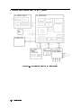
Servicing at a Glance
vi
The color display is used in HP 70000 Series modular measurement systems. A standard
modular spectrum analyzer system includes a mainframe with an RF section, IF section, local
oscillator, an optional display, and an optional precision frequency reference.
Software and documentation supplied
This service guide is part of an Option OB3 package which includes:
HP 70004A Service Guide
HP 70004A Component Level Information Packages
Tools needed
Before servicing, refer to Chapter 5 for a list of the tools and accessories that may be needed
during servicing.
Antistatic precautions
Electrical components are easily damaged by small amounts of static electricity. If possible,
work at a static-safe work station. For further information, refer to \Preparing a Static-Safe
Work Station" in Chapter 4.
vii
In This Book
This book describes all of the service procedures necessary to test, adjust, calibrate,
troubleshoot, and repair your color display in an HP 70000 Series modular measurement
system.
Each module in the HP 70000 Series modular measurement system has its own service guide.
For further information related to the servicing of additional and alternate modules that can be
used in this system, refer to that module's service guide.
This service guide is part of an Option OB3 package which consists of two manuals.
Manual 1
Chapter 1 provides information to help get you started so that your color display is serviced
properly.
Chapter 2 would have contained information needed to use module verication software, but
your color display does not require this software because there are no module verication
tests.
Chapter 3 contains information to help identify and resolve some common problems that may
occur with your color display before extensive servicing.
Chapter 4 contains information about troubleshooting your color display. It presents
information on preparing a static-safe work station and then it presents a set of
troubleshooting procedures that can be used to optimize repair time.
Chapter 5 contains tables with a complete listing of all equipment that may be required for
servicing.
Chapter 6 contains the setups for all adjustment procedures that are used to optimize module
performance when assemblies are changed, repaired, or adjusted.
Chapter 7 would have contained information needed to perform all module verication tests,
but your color display does not have any module verication tests.
Chapter 8 would have contained information needed for all equipment calibration
procedures, but your color display does not have any equipment calibration procedures.
Chapter 9 contains procedures for removal and replacement of major assemblies in your
color display. It also contains information needed to order mechanical parts for your
color display.
Chapter 10 contains information on all overall parts identication drawings that should be
used when performing the troubleshooting procedures descibed in this service guide.
An index is also added at the end of this service guide to aid the user in nding key items of
interest.
Manual 2
Manual 2 contains packets of component-level repair information for each color display
board assembly that has eld-replaceable parts. Each packet includes the parts list,
component-location drawing, and schematics for a specic board-assembly part number. This
manual also contains a table that can be used to cross reference dierent board assemblies
that have dierent serial prex breaks.
Before you begin servicing, refer to \Preparing a Static-Safe Work Station" in Chapter 4.
viii
Contents
1. Getting Started
What Is Servicing? . . . . . . . . . . . . . . . . . . .
When Is Servicing Needed? . . . . . . . . . . . . . . .
If You Want Hewlett-Packard to Service Your Color Display
Determining Your Color Display's Serial Number . . . .
Returning Your Color Display for Service . . . . . . .
.
.
.
.
.
.
.
.
.
.
.
.
.
.
.
.
.
.
.
.
.
.
.
.
.
.
.
.
.
.
.
.
.
.
.
.
.
.
.
.
.
.
.
.
.
.
.
.
.
.
.
.
.
.
.
1-2
1-2
1-3
1-3
1-5
3. Before Extensive Servicing
If an E is Flashing in the Display Status Box . . . . . . . . . . . . . . . . . .
3-2
2. Module Verication Software
4. Troubleshooting
Safety Considerations . . . . . . . . . . . . . . . . . . . . . . .
Preparing a Static-Safe Work Station . . . . . . . . . . . . . . . .
Reducing ESD Damage . . . . . . . . . . . . . . . . . . . . . .
Static-Safe ESD Accessories . . . . . . . . . . . . . . . . . . .
If Display-Disruptive Errors Occur . . . . . . . . . . . . . . .
If Hardware-Warning Errors Messages (6000 {6999) Occur . . . .
If Hardware Error Messages (7000{7999) Occur . . . . . . . . .
Overall Block Diagram of Color Display . . . . . . . . . . . . .
Display Troubleshooting . . . . . . . . . . . . . . . . . . . . . .
Diagnostic Tools . . . . . . . . . . . . . . . . . . . . . . . . . .
A4 Power Supply Diagnostic Tools . . . . . . . . . . . . . . . .
Display Diagnostic Tools, Turn-On . . . . . . . . . . . . . . . . .
Display Diagnostic Tools, Front-Panel . . . . . . . . . . . . . . .
Display Diagnostic Tools, Failures . . . . . . . . . . . . . . . . .
HP-MSIB Diagnostic Tools . . . . . . . . . . . . . . . . . . . .
Test Pattern Diagnostic Tools . . . . . . . . . . . . . . . . . . .
Troubleshooting the A4 Power Supply . . . . . . . . . . . . . . . .
State 1. No Observed Power. The Front-Panel Power Indicator is O.
State 2. The FAULT Indicator Light (A4DS6) is Lit. . . . . . . . . .
State 3. The I LIMIT Fault Indicator Light (A4DS5) is Lit. . . . . .
State 4. Front-Panel LINE Indicator is O. Modules Have Power. . .
State 5. Normal Operation Except Display is Blank. . . . . . . . .
State 6. Front-Panel Indicators Normal, No Module Power. . . . . .
Component-Level Hints . . . . . . . . . . . . . . . . . . . . .
Display and Processor Troubleshooting . . . . . . . . . . . . . . .
Identifying the Failed Assembly . . . . . . . . . . . . . . . . .
State 7. Display Disruptive Messages. . . . . . . . . . . . . . . .
State 8. Abnormal CRT Display. . . . . . . . . . . . . . . . . .
State 9. Memory Card Troubleshooting. . . . . . . . . . . . . . .
A5 Processor Component-level Troubleshooting . . . . . . . . . .
Select Mode Tests . . . . . . . . . . . . . . . . . . . . . . .
Service Tests . . . . . . . . . . . . . . . . . . . . . . . . .
Troubleshooting LEDs and DIP Switch Map . . . . . . . . . . .
.
.
.
.
.
.
.
.
.
.
.
.
.
.
.
.
.
.
.
.
.
.
.
.
.
.
.
.
.
.
.
.
.
.
.
.
.
.
.
.
.
.
.
.
.
.
.
.
.
.
.
.
.
.
.
.
.
.
.
.
.
.
.
.
.
.
.
.
.
.
.
.
.
.
.
.
.
.
.
.
.
.
.
.
.
.
.
.
.
.
.
.
.
.
.
.
.
.
.
.
.
.
.
.
.
.
.
.
.
.
.
.
.
.
.
.
.
.
.
.
.
.
.
.
.
.
.
.
.
.
.
.
.
.
.
.
.
.
.
.
.
.
.
.
.
.
.
.
.
.
.
.
.
.
.
.
.
.
.
.
.
.
.
.
.
4-1
4-2
4-3
4-3
4-4
4-7
4-8
4-10
4-11
4-13
4-13
4-13
4-13
4-14
4-14
4-15
4-16
4-20
4-23
4-26
4-28
4-29
4-31
4-32
4-33
4-33
4-33
4-33
4-34
4-34
4-34
4-38
4-39
Contents-1
Service Test List . . . . . . . . . . . . . . . . . . .
HP-MSIB and HP-IB Troubleshooting . . . . . . . . . . .
State 10. HP-MSIB Fault Indicator Light is Lit. . . . . . .
State 11. HP-MSIB Troubleshooting, HP-MSIB Light is O.
State 12. HP-IB Troubleshooting . . . . . . . . . . . .
.
.
.
.
.
.
.
.
.
.
.
.
.
.
.
.
.
.
.
.
.
.
.
.
.
.
.
.
.
.
.
.
.
.
.
.
.
.
.
.
.
.
.
.
.
.
.
.
.
.
4-41
4-47
4-48
4-50
4-53
5. Recommended Test Equipment Tables
6. Adjustment Procedures
Power Supply Adjustments
Low Line Adjustment . .
Current Limit Adjustment
Output Voltage Adjustment
+65 Volt Adjustment . . .
Monitor Adjustments . . .
.
.
.
.
.
.
.
.
.
.
.
.
.
.
.
.
.
.
.
.
.
.
.
.
.
.
.
.
.
.
.
.
.
.
.
.
.
.
.
.
.
.
.
.
.
.
.
.
.
.
.
.
.
.
.
.
.
.
.
.
.
.
.
.
.
.
.
.
.
.
.
.
.
.
.
.
.
.
.
.
.
.
.
.
.
.
.
.
.
.
.
.
.
.
.
.
.
.
.
.
.
.
.
.
.
.
.
.
.
.
.
.
.
.
.
.
.
.
.
.
.
.
.
.
.
.
.
.
.
.
.
.
.
.
.
.
.
.
.
.
.
.
.
.
.
.
.
.
.
.
.
.
.
.
.
.
6-2
6-4
6-7
6-9
6-11
6-13
.
.
.
.
.
.
.
.
.
.
.
.
.
.
.
.
.
.
.
.
.
.
.
.
.
.
.
.
.
.
.
.
.
.
.
.
.
.
.
.
.
.
.
.
.
.
.
.
.
.
.
.
.
.
.
.
.
.
.
.
.
.
.
.
.
.
.
.
.
.
.
.
.
.
.
.
.
.
.
.
.
.
.
.
.
.
.
.
.
.
.
.
.
.
.
.
.
.
.
.
.
.
.
.
.
.
.
.
.
.
.
.
.
.
.
.
.
.
.
.
.
.
.
.
.
.
.
.
.
.
.
.
.
.
.
.
.
.
.
.
.
.
.
.
.
.
.
.
.
.
.
.
.
.
.
.
.
.
.
.
.
.
.
.
.
.
.
.
.
.
.
.
.
.
.
9-2
9-4
9-8
9-11
9-14
9-17
9-18
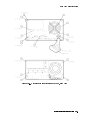
Front View Identication . . . . . . . .
Top View of Monitor Identication . . .
Rear View Identication . . . . . . . .
Bottom View Identication . . . . . . .
Side View Identication . . . . . . . .
A5 Processor Service View Identication
.
.
.
.
.
.
.
.
.
.
.
.
.
.
.
.
.
.
.
.
.
.
.
.
.
.
.
.
.
.
.
.
.
.
.
.
.
.
.
.
.
.
.
.
.
.
.
.
.
.
.
.
.
.
.
.
.
.
.
.
.
.
.
.
.
.
.
.
.
.
.
.
.
.
.
.
.
.
.
.
.
.
.
.
.
.
.
.
.
.
.
.
.
.
.
.
.
.
.
.
.
.
.
.
.
.
.
.
. 10-2
. 10-4
. 10-6
. 10-8
. 10-9
. 10-10
7. Module Verication Tests
8. Equipment Calibration
9. Replacing Major Assemblies
A1 Front Panel . . . . . .
A3 Monitor/Monitor Bracket
A4 Power Supply . . . . .
A5 Processor . . . . . . .
A6 HP-MSIB . . . . . . . .
Rear Frame . . . . . . . .
Custom Key-Panel Assembly
10. Overall Parts Identication Drawings
Index
Contents-2
Figures
1-1.
4-1.
4-2.
4-3.
4-4.
4-5.
4-6.
4-7.
4-8.
4-9.
4-10.
6-1.
6-2.
6-3.
6-4.
6-5.
9-1.
9-2.
9-3.
9-4.
9-5.
9-6.
9-7.
9-8.
9-9.
10-1.
10-2.
10-3.
10-4.
Typical Serial Number Label . . . . . . . . . . . . . . .
Static-Safe Work Station . . . . . . . . . . . . . . . . .
Overall Block Diagram of Color Display . . . . . . . . . .
A5 Processor Diagnostics Location . . . . . . . . . . . .
A4 Power Supply Indicators and Fuses (Front) . . . . . . .
A4 Power Supply Indicators and Fuses (Back) . . . . . . .
Voltage Selector Switch . . . . . . . . . . . . . . . . .
A5 Processor Diagnostics Locations . . . . . . . . . . . .
A5 Processor Switch Locations . . . . . . . . . . . . . .
Front-Panel HP-MSIB Fault Indicator Light . . . . . . . .
HP-MSIB Module Connector . . . . . . . . . . . . . . .
Low Line Adjustment . . . . . . . . . . . . . . . . . .
Current Limit Adjustment . . . . . . . . . . . . . . . .
Output Voltage Adjustment . . . . . . . . . . . . . . . .
+65 Volt Adjustment . . . . . . . . . . . . . . . . . . .
Monitor Adjustments . . . . . . . . . . . . . . . . . . .
A1 Front Panel Removal/Replacement . . . . . . . . . . .
A3 Monitor/Monitor Bracket Removal/Replacement (1 of 2) .
A3 Monitor/Monitor Bracket Removal/Replacement (2 of 2) .
A4 Power Supply Removal/Replacement . . . . . . . . . .
A5 Processor Removal/Replacement . . . . . . . . . . . .
A6 HP-MSIB Removal/Replacement . . . . . . . . . . . .
Rear Frame Removal/Replacement . . . . . . . . . . . .
Installing the Custom Keypad (Without Button) . . . . . .
Installing the Custom Keypad . . . . . . . . . . . . . . .
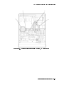
Overall Parts Identication Drawing, Front View . . . . .
Overall Parts Identication Drawing, Top View . . . . . .
Overall Parts Identication Drawing, Rear View . . . . . .
Overall Parts Identication Drawing, A5 Service View . . .
.
.
.
.
.
.
.
.
.
.
.
.
.
.
.
.
.
.
.
.
.
.
.
.
.
.
.
.
.
.
.
.
.
.
.
.
.
.
.
.
.
.
.
.
.
.
.
.
.
.
.
.
.
.
.
.
.
.
.
.
.
.
.
.
.
.
.
.
.
.
.
.
.
.
.
.
.
.
.
.
.
.
.
.
.
.
.
.
.
.
.
.
.
.
.
.
.
.
.
.
.
.
.
.
.
.
.
.
.
.
.
.
.
.
.
.
.
.
.
.
.
.
.
.
.
.
.
.
.
.
.
.
.
.
.
.
.
.
.
.
.
.
.
.
.
.
.
.
.
.
.
.
.
.
.
.
.
.
.
.
.
.
.
.
.
.
.
.
.
.
.
.
.
.
.
.
.
.
.
.
.
.
.
.
.
.
.
.
.
.
.
.
.
.
.
.
.
.
.
.
.
.
.
.
.
.
.
.
.
.
.
.
.
.
.
.
.
.
.
.
.
.
.
.
.
.
.
.
.
.
.
.
.
1-3
.
4-2
. 4-10
. 4-12
. 4-17
. 4-18
. 4-20
. 4-39
. 4-40
. 4-49
. 4-52
6-5
.
6-7
.
6-9
.
. 6-11
. 6-13
9-3
.
9-6
.
9-7
.
. 9-10
. 9-13
. 9-16
. 9-17
. 9-18
. 9-19
. 10-3
. 10-5
. 10-7
. 10-11
Hewlett-Packard Sales and Service Oces . . . . . . . . . . . . .
Packaging for an 8/8 Module . . . . . . . . . . . . . . . . . . .
Static-Safe ESD Accessories . . . . . . . . . . . . . . . . . . .
Display-Disruptive Errors and Their Associated A5DS2 LED Patterns
Decimal/Hexadecimal Conversion . . . . . . . . . . . . . . . . .
Select Mode Tests . . . . . . . . . . . . . . . . . . . . . . . .
Test Descriptions . . . . . . . . . . . . . . . . . . . . . . . . .
Recommended Test Equipment . . . . . . . . . . . . . . . . . .
A4 Power Supply Adjustable Components . . . . . . . . . . . . .
Overall Parts Identication Drawing, A5 Service View . . . . . . .
.
.
.
.
.
.
.
.
.
.
.
.
.
.
.
.
.
.
.
.
.
.
.
.
.
.
.
.
.
.
.
.
.
.
.
.
.
.
.
.
1-4
.
1-6
.
4-3
.
.
4-4
. 4-15
. 4-35
. 4-36
5-1
.
6-2
.
. 10-10
Tables
1-1.
1-2.
4-1.
4-2.
4-3.
4-4.
4-5.
5-1.
6-1.
10-1.
Contents-3
1
Getting Started
This chapter provides information to help get you started so that your color display is serviced
properly.
This chapter answers the questions \What Is Servicing?" and \When Is Servicing Needed?".
It then describes the procedures used to return your color display to Hewlett-Packard for
servicing.
Getting Started 1-1
What Is Servicing?
Servicing includes testing, adjusting, calibrating, troubleshooting, and repairing.
There are dierent categories of testing available. These categories are module verication
tests, system verication of operation tests, and system performance tests.
Module
Module verication tests are used to test modules so that when assembled
Verication Tests into a system, the system meets the system's specications. These sets of
tests are used during servicing.
System
System verication of operation tests are used to verify the proper
Verication of
operation of an instrument and to verify that the instrument meets
Operation Tests approximately 80% of its measurement related specications. These sets of
tests are subsets of system performance tests.
System
System performance tests are used to verify the proper operation of a
Performance
complete modular measurement system (MMS) to full system specications.
Tests
This service guide provides information related to testing, adjusting, calibrating,
troubleshooting, and repairing your color display; it also provides information on module
verication tests. These sets of tests are used during servicing.
For information related to system verication of operation tests, refer to the HP 70000 Modular
Spectrum Analyzer Installation and Verication Manual, and for information related to
system performance tests, refer to the documentation for HP 11990A system performance test
software.
When Is Servicing Needed?
Servicing is needed:
if error messages are displayed on your HP 70000 Series display
if an ERROR LED or FAULT LED is on
to perform repairs or adjustments or both
to verify the correct operation of your color display
or, if applicable, when upgrading rmware
If you determine that your color display needs servicing, you can perform the servicing
yourself or, you can return your color display to a Hewlett-Packard service center.
1-2 Getting Started
If You Want Hewlett-Packard to Service Your Color Display
Before calling Hewlett-Packard or returning your color display for service, please read your
warranty information. Warranty information is printed at the front of this service guide.
In any correspondence or telephone conversations, refer to the color display by its full model
number and full serial number. With this information, the Hewlett-Packard representative can
determine whether your unit is still within its warranty period.
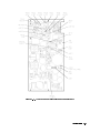
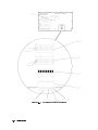
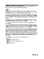
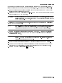
Determining Your Color Display's Serial Number
When a module is manufactured by Hewlett-Packard, it is given a unique serial number. This
serial number is attached to a label on the front frame or front panel of the module. A serial
number label is in two parts. (Refer to Figure 1-1.) The rst part makes up the serial number
prex and consists of four digits and a letter. The second part makes up the serial number
sux and consists of the last ve digits on the serial number label. The serial number prex is
the same for all identical modules; it only changes when a change in the electrical or physical
functionallity is made. The serial number sux, however, changes sequentially and is dierent
for each module.
Figure 1-1. Typical Serial Number Label
Getting Started 1-3
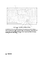
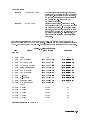
Table 1-1. Hewlett-Packard Sales and Service Oces
US FIELD OPERATIONS
HEADQUARTERS
Hewlett-Packard Company
19320 Pruneridge Avenue
Cupertino, CA 95014, USA
(800) 752-0900
California
Hewlett-Packard Co.
1421 South Manhattan Ave.
Fullerton, CA 92631
(714) 999-6700
EUROPEAN OPERATIONS
HEADQUARTERS
Hewlett-Packard S.A.
150, Route du Nant-d'Avril
1217 Meyrin 2/Geneva
Switzerland
(41 22) 780.8111
Hewlett-Packard Company
3495 Deer Creek Rd.
Palo Alto, California 94304-1316
(415) 857-5027
France
Hewlett-Packard Australia Ltd.
31-41 Joseph Street (P.O. Box 221)
Blackburn, Victoria 3130
(61 3) 895-2895
Hewlett-Packard France
1 Avenue Du Canada
Zone D'Activite De Courtaboeuf
F-91947 Les Ulis Cedex
France
(33 1) 69 82 60 60
Hewlett-Packard Co.
301 E. Evelyn
Mountain View, CA 94041
(415) 694-2000
Germany
Hewlett-Packard GmbH
Colorado
Hewlett-Packard-Strasse
Hewlett-Packard Co.
61352 Bad Homburg
24 Inverness Place, East
Germany
Englewood, CO 80112
(+49 6172) 16-0
(303) 649-5000
Georgia
Hewlett-Packard Co.
2000 South Park Place
Atlanta, GA 30339
(404) 955-1500
Illinois
Hewlett-Packard Co.
5201 Tollview Drive
Rolling Meadows, IL 60008
(708) 342-2000
New Jersey
Hewlett-Packard Co.
150 Green Pond Road
Rockaway, NJ 07866
(201) 586-5400
Texas
Hewlett-Packard Co.
930 E. Campbell Rd.
Richardson, TX 75081
(214) 231-6101
1-4 Getting Started
INTERCON OPERATIONS
HEADQUARTERS
Australia
Canada
Hewlett-Packard (Canada) Ltd.
17500 South Service Road
Trans-Canada Highway
Kirkland, Quebec H9J 2X8
Canada
(514) 697-4232
Japan
Yokogawa-Hewlett-Packard Ltd.
Hewlett-Packard Ltd.
1-27-15 Yabe, Sagamihara
Eskdale Road, Winnersh Triangle Kanagawa 229, Japan
Wokingham, Berkshire RG11 5DZ (81 427) 59-1311
England
(44 734) 696622
Great Britain
China
China Hewlett-Packard, Co.
38 Bei San Huan X1 Road
Shuang Yu Shu
Hai Dian District
Beijing, China
(86 1) 256-6888
Singapore
Hewlett-Packard Singapore
Pte. Ltd.
Alexandra P.O. Box 87
Singapore 9115
(65) 271-9444
Taiwan
Hewlett-Packard Taiwan
8th Floor, H-P Building
337 Fu Hsing North Road
Taipei, Taiwan
(886 2) 712-0404
Returning Your Color Display for Service
Hewlett-Packard has sales and service oces around the world to provide complete support for
your color display. To obtain servicing information or to order replacement parts, contact the
nearest Hewlett-Packard sales and service oce listed in Table 1-1.
Use the following procedure to return your color display to Hewlett-Packard for service:
1. Fill out a service tag (available at the end of this service guide) and attach it to the
instrument. Please be as specic as possible about the nature of the problem. Send a copy
of any or all of the following information:
any error messages that appeared on the HP 70000 Series display
a completed Performance Test record
any other specic data on the performance of the color display
CAUTION
Damage can result if the original packaging materials are not used. Packaging
materials should be anti-static and should cushion the color display on all sides.
Never use styrene pellets in any shape as packaging materials. They do not
adequately cushion the instrument or prevent it from moving in the shipping
container. Styrene pellets can also cause equipment damage by generating
static electricity or by lodging in fan motors.
2. Place the color display in its original packaging materials.
If the original packaging materials are not available, you can contact a Hewlett-Packard
sales and service oce to obtain information on packaging materials or you may use an
alternative packing material referred to as \bubble-pack". One of the companies that makes
bubble-pack is Sealed Air Corportation of Commerce, California, 90001.
3. Surround the color display with at least 3 to 4 inches of its original packing material or
bubble-pack to prevent the color display from moving in its shipping container.
4. Place the color display, after wrapping it with packing material, in its original shipping
container or a strong shipping container that is made of double-walled corrugated cardboard
with 159 kg (350 lb) bursting strength.
The shipping container must be both large enough and strong enough to accommodate your
color display and allow at least 3 to 4 inches on all sides for packing material.
5. Seal the shipping container securely with strong nylon adhesive tape.
6. Mark the shipping container \FRAGILE, HANDLE WITH CARE" to help ensure careful
handling.
7. Retain copies of all shipping papers.
Getting Started 1-5
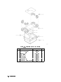
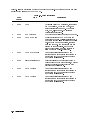
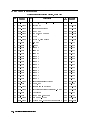
Table 1-2. Packaging for an 8/8 Module
Item
1
2
3
4
5
6
7
8
1-6 Getting Started
Description
Corrugated Carton (Top)
Foam Corner-Pads
Flat End-Cap
Static Sheet
Front Cover
Foam Plastic
Corrugated Pad
Corrugated Carton (Outer)
HP Part Number Qty
9211-6785
5040-6967
9220-4962
9222-1806
5040-6974
4208-1210
9220-5072
9211-7065
1
8
1
1
1
1
1
1
2
Module Verication Software
Module Verication Software is a program that is designed to automate module verication
tests and adjustment procedures.
Note
The HP 70004A color display does not have any automated module verication
tests and therefore does not use module verication software.
The HP 70004A color display's tests and adjustment procedures are not
automated; they require the user to perform step-by-step manual procedures.
Module Verication Software 2-1
3
Before Extensive Servicing
This chapter contains information to help identify and resolve some common problems that
may occur with your color display before extensive servicing.
Symptoms to various problems are listed at the top of each page. Most symptoms have a brief
description or explanation to help provide more insight into their cause. A possible cause for
the symptom and a checklist of possible solutions are then presented. Use this checklist as an
aid to correct the problem.
If you determine that your color display needs further servicing and your color display is
not experiencing any of the symptoms presented in this chapter, refer to Chapter 4 for
information about troubleshooting your color display and Table 5-1 for a list of recommended
test equipment to use when assemblies are changed, repaired, or adjusted.
Note
If you decide to perform the servicing yourself, prepare a static-safe work
station before you begin any servicing procedures. (Refer to \Preparing a
Static-Safe Work Station" in Chapter 4.)
If you do not wish to perform the servicing yourself, return your color display
to a Hewlett-Packard service center. (Refer to \If You Want Hewlett-Packard to
Service Your Color Display" in Chapter 1.)
Before Extensive Servicing 3-1
If an E is Flashing in the Display Status Box
On power-up, the E in the display status box will ash if the external HP-MSIB loop is not yet
ready. The ashing E will stop when the external loop is established. No error messages are
displayed.
The ashing E fault indicator light in the display status box performs a similar function as the
ashing ERR fault indicator on HP 70000 Series modular spectrum analyzer system.
A ashing E or ERR indicates one of the following three problems:
An HP-MSIB backplane error (or module fault) has been detected at power-up which may
prevent normal HP-MSIB communications (and normal error reporting). This problem must
be repaired before any predictable system operation can occur.
The A6 HP-MSIB is not receiving +5 V bias.
The A6 HP-MSIB is defective.
The most probable cause for a ashing E or ERR in a new system occurs when two modules
in the same system have the same HP-MSIB address (row and column). This will generate a
backplane error. The display's address map will always lock-up under this condition.
To solve this problem:
Wait for the external HP-MSIB loop to become ready or,
Refer to \State 11. HP-MSIB Troubleshooting, HP-MSIB Light is O." in Chapter 4
If necessary, obtain service from Hewlett-Packard. (Refer to \If You Want Hewlett-Packard to
Service Your Color Display" in Chapter 1.)
3-2 Before Extensive Servicing
4
Troubleshooting
This chapter contains information about troubleshooting your color display. It presents
information on preparing a static-safe work station and then it presents a set of troubleshooting
procedures that can be used to optimize repair time.
Safety Considerations
This instrument has been designed in accordance with international safety standards. This
manual contains information, cautions, and warnings which must be followed to ensure safe
operation and to retain the instrument in a safe condition. Service and adjustments should be
performed only by qualied service personnel.
DANGER
CAUTION
These procedures require access to the interior of the color display,
only qualied service personnel should perform the servicing
procedures.
Use electrostatic discharge (ESD) precautions when performing any
servicing.
Do not touch the A4 power supply with your hands while power is
applied.
The A4 power supply has lethal voltages, with lethal currents, in all
areas for at least three minutes after power is turned o.
Use of a Ground Fault Interrupter (GFI), a Line-Isolated Variable Mains
Transformer (VARIAC), and extreme care are mandatory when servicing
the A4 power supply.
Service personnel must use a >>1 M
resistor-isolated wrist strap or
heel strap while handling the A4 power supply.
To avoid damaging the HP 70004A color display module connectors, the
HP 70004A color display must be o before installing or removing any
modules.
Do not use erasers to clean the pin connector contacts. Erasers generate
static electricity and remove the thin gold plating, which degrades the
electrical quality of the contacts. Do not use paper of any kind to clean the pin
connector contacts. Paper or lint particles left on the contact surface can cause
intermittent electrical connections. Do not touch the pin connector contacts or
trace surfaces with bare hands. Always handle board assemblies by the edges.
The pin connector contacts of PC board assemblies may be cleaned by using a
lint-free cloth with a solution of 80% electronics-grade isopropyl alcohol and
20% de-ionized water. Perform this procedure at a static-free work station.
Troubleshooting 4-1
Preparing a Static-Safe Work Station
Electrostatic discharge (ESD) can damage or destroy electronic components. Therefore,
all work performed on assemblies consisting of electronic components should be done at a
static-safe work station.
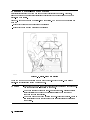
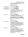
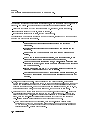
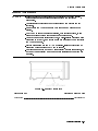
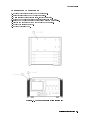
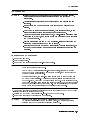
Figure 4-1 shows an example of a static-safe work station. Two types of ESD protection are
shown:
a conductive table mat and wrist strap combination
a conductive oor mat and heel strap combination
Figure 4-1. Static-Safe Work Station
These two types of ESD protection must be used together. Refer to Table 4-1 for a list of
static-safe accessories and their HP part numbers.
CAUTION
4-2 Troubleshooting
Do not touch the edge-connector contacts or trace surfaces with bare hands.
Always handle board assemblies by the edges.
Do not use erasers to clean the edge-connector contacts. Erasers generate
static electricity and degrade the electrical quality of the contacts by
removing the thin gold plating.
Do not use paper of any kind to clean the edge-connector contacts. Paper or
lint particles left on the contact surface can cause intermittent electrical
connections.
Reducing ESD Damage
To help reduce the amount of ESD damage that occurs during testing and servicing use the
following guidelines:
Be sure that all instruments are properly earth-grounded to prevent buildup of static charge.
Personnel should be grounded with a resistor-isolated wrist strap before touching the center
pin of any connector and before removing any assembly from a piece of equipment.
Use a resistor-isolated wrist strap that is connected to the HP 70000 Series modular spectrum
analyzer system mainframe's chassis. If you do not have a resistor-isolated wrist strap, touch
the chassis frequently to equalize any static charge.
Before connecting any coaxial cable to an instrument connector for the rst time each day,
momentarily short the center and outer conductors of the cable together.
Handle all PC board assemblies and electronic components only at static-safe work stations.
Store or transport PC board assemblies and electronic components in static-shielding
containers.
PC board assembly edge-connector contacts may be cleaned by using a lintfree cloth with a
solution of 80% electronics-grade isopropyl alcohol and 20% deionized water. This procedure
should be performed at a static-safe work station.
Static-Safe ESD Accessories
Table 4-1. Static-Safe ESD Accessories
HP Part
Number
Description
Set includes: 3M static control mat 0.6 m 2 1.2 m (2 ft 2 4 ft) and 4.6 m
(15 ft) ground wire. (The wrist-strap and wrist-strap cord are not included.
They must be ordered separately.)
9300-0865
Ground wire, 4.6 m (15 ft)
9300-0980
Wrist-strap cord 1.5 m (5 ft)
9300-1383
Wrist-strap, color black, stainless steel, without cord, has four adjustable
links and a 7 mm post-type connection.
9300-1169
ESD heel-strap (reusable 6 to 12 months).
Order the following by calling HP DIRECT at (800) 538-8787 or through any Hewlett-Packard
Sales and Service Oce.
9300-0797
Troubleshooting 4-3
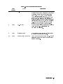
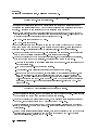
If Display-Disruptive Errors Occur
Display-disruptive errors are those that interfere with normal display operation and error
reporting. The testing will stop at the rst failed test.
The display-disruptive error messages are shown in two ways depending on whether or not the
Test Mode switch is set:
if the Test Mode switch is not set, errors are displayed in large block letters
if the Test Mode switch is set, errors are shown as an LED pattern on the A5 processor
In test mode, the LEDs indicate which test has failed. When the display indicates a
display-disruptive error, the error LEDs (A5DS2) will light. The error messages indicated by
these LED patterns are a duplication of the error messages displayed on the CRT. Because
the screen may be blank, this may be the only way to tell what error is indicated.
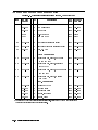
Table 4-2.
Display-Disruptive Errors and Their Associated A5DS2 LED Patterns
Error Messages
= LED o, = LED on
RAM DATA ERROR (U19)
RAM DATA ERROR (U20)
RAM ADDR ERROR
ROM 23 CHECKSUM
ROM 24 CHECKSUM
ROM 25 CHECKSUM
ROM 26 CHECKSUM
A5 8041 INTERFACE
A5 GRAPHICS VRAM
A5 GRAPHICS DRAM
A5 GRAPHICS PROCESSOR
RAM DATA ERROR (U19)
RAM DATA ERROR (U20)
RAM ADDR ERROR
4-4 Troubleshooting
A5DS2 LED Pattern
A5DS2 LED Pattern: A5DS2 LED Pattern: These display-disruptive errors occur when the processor on the
A5 processor recieves an unrecognizable command.
A test of CMOS RAM has failed. Data is cycled through all the
address locations on the data bus. Each time data is written, it
is read back and compared with the written data. At least one
comparison failed.
To solve this problem:
1. Replace the A5 processor.
A5DS2 LED Pattern: This display-disruptive error occurs when the processor on the
A5 processor recieves an unrecognizable command.
If Display-Disruptive Errors Occur
A5 ROM (U23) CHECKSUM
A5 ROM (U24) CHECKSUM
A5 ROM (U25) CHECKSUM
A5 ROM (U26) CHECKSUM
A5 8041 INTERFACE
A5 GRAPHICS DRAM
A5 GRAPHICS VRAM
A test of CMOS RAM has failed. The data in CMOS RAM is read,
saved, and complemented. Every other address is then tested
to see if the data is unchanged.
To solve this problem:
1. Replace the A5 processor.
A5DS2 LED Pattern: A5DS2 LED Pattern: A5DS2 LED Pattern: A5DS2 LED Pattern: These display-disruptive errors occur when the processor on the
A5 processor recieves an unrecognizable command.
A checksum was calculated on all ROMs, one or more ROMs
failed. Replace the defective ROM.
To solve this problem:
1. Replace the A5 processor.
A5DS2 LED Pattern: This display-disruptive error occurs when the processor on the
A5 processor recieves an unrecognizable command.
Communications failed between the A5 8041 processor chip
and the A5 main processor chip. The 8041 processor chip is
instructed to send a data sequence to the main processor chip,
which if received correctly should verify the 8041 and the link
to it.
To solve this problem:
1. Replace the A5 processor.
A5DS2 LED Pattern: This display-disruptive error occurs when the processor on the
A5 processor recieves an unrecognizable command.
A test of the Dynamic RAM has failed. An address register is
increased by one (increment) as a data pattern is decreased by
one (decrement). The processor's attempt to write and verify
the data pattern to the Dynamic RAM has failed.
To solve this problem:
1. Replace the A5 processor.
A5DS2 LED Pattern: This display-disruptive error occurs when the processor on the
A5 processor recieves an unrecognizable command.
A test of the Video RAM has failed. An address register is
increased by one (increment) as a data pattern is decreased by
one (decrement). The processor's attempt to write and verify
the data pattern to the Video RAM has failed.
To solve this problem:
Troubleshooting 4-5
If Display-Disruptive Errors Occur
1. Replace the A5 processor.
A5 GRAPHICS PROCESSOR A5DS2 LED Pattern: This display-disruptive error occurs when the processor on the
A5 processor recieves an unrecognizable command.
A test of the Graphics Processor System has failed. The
processor has attempted to read and verify the contents of
a location in the graphics system DRAM. The GSP loads this
location with a known pattern during its initialization.
To solve this problem:
1. Replace the A5 processor.
4-6 Troubleshooting
If Hardware-Warning Errors Messages (6000 {6999) Occur
If Hardware-Warning Errors Messages (6000 {6999) Occur
The A5 RAM memory failed a checksum test.
6002 A5 RAM Checksum (battery?)
To solve this problem:
1. Cycle the line power to try and clear the error.
2. Replace the battery BT1 located on the A5 processor.
3. If the problem persists, replace the A5 processor. (Refer to Chapter 9.)
Troubleshooting 4-7
If Hardware Error Messages (7000{7999) Occur
Hardware errors are generated when a module in the HP 70000 Series modular spectrum
analyzer system is not working properly. These errors can occur at any time. Hardware errors
range from 7000{7999.
One or more of the following hardware error messages may appear on your system display:
7038 A5 Error in 8041
This hardware error occurs when communications fail between the A5 8041 processor
and the main processor. The 8041 processor is instructed to send a data sequence to
the main processor, which if received correctly should verify the 8041 and the link to
it.
To solve this problem:
1. Replace the A5 processor.
2. If necessary, obtain service from Hewlett-Packard. (Refer to \If You Want
Hewlett-Packard to Service Your Color Display" in Chapter 1.)
7040 A5 GSP Checksum error
This hardware error occurs when a test of the Graphics Processor System has failed. A
test pattern was loaded into the Video RAM by the graphics processor. A checksum of
the Video RAM was calculated by the processor.
To solve this problem:
1. Replace the A5 processor.
2. If necessary, obtain service from Hewlett-Packard. (Refer to \If You Want
Hewlett-Packard to Service Your Color Display" in Chapter 1.)
7060 A5 RAM Data (U20)
7061 A5 RAM Data (U19)
This hardware error occurs when a test of CMOS RAM has failed. Data is cycled
through all the address locations on the data bus. Each time data is written , it is read
back and compared with the written data. At least one test failed.
To solve this problem:
1. Replace the A5 processor.
2. If necessary, obtain service from Hewlett-Packard. (Refer to \If You Want
Hewlett-Packard to Service Your Color Display" in Chapter 1.)
7062 RAM Address
This hardware error occurs when a test of CMOS RAM has failed. The data in CMOS
RAM is read, saved, and complemented. Every other address is then tested to see if
the data is unchanged.
To solve this problem:
1. Replace the A5 processor.
2. If necessary, obtain service from Hewlett-Packard. (Refer to \If You Want
Hewlett-Packard to Service Your Color Display" in Chapter 1.)
4-8 Troubleshooting
If Hardware Error Messages (7000{7999) Occur
7063
7064
7065
7066
A5 ROM (U24) Checksum
A5 ROM (U26) Checksum
A5 ROM (U23) Checksum
A5 ROM (U25) Checksum
7090
A5 Graphics DRAM error
7091
A5 Graphics VRAM error
7092
A5 Graphics Processor
This hardware error occurs when a checksum is calculated on all ROMs.
To solve this problem:
1. Replace the defective ROM.
2. If the problem persists, replace the A5 processor.
3. If necessary, obtain service from Hewlett-Packard. (Refer to \If You Want
Hewlett-Packard to Service Your Color Display" in Chapter 1.)
This hardware error occurs when a test of the Dynamic RAM has failed. An address
register is increased by one (increment) as a data pattern is decreased by one
(decrement). The processor's attempt to write and verify the data pattern to the
Dynamic RAM has failed.
To solve this problem:
1. Replace the A5 processor.
2. If necessary, obtain service from Hewlett-Packard. (Refer to \If You Want
Hewlett-Packard to Service Your Color Display" in Chapter 1.)
This hardware error occurs when a test of the Video RAM has failed. An address
register is increased by one (increment) as a data pattern is decreased by one
(decrement). The processor's attempt to write and verify the data pattern to the
Video RAM has failed.
To solve this problem:
1. Replace the A5 processor.
2. If necessary, obtain service from Hewlett-Packard. (Refer to \If You Want
Hewlett-Packard to Service Your Color Display" in Chapter 1.)
This hardware error occurs when a test of the Graphics Processor System has failed.
The processor has attempted to read and verify the contents of a location in the
graphics system DRAM. The GSP loads this location with a known pattern during its
initialization.
To solve this problem:
1. Replace the A5 processor.
2. If necessary, obtain service from Hewlett-Packard. (Refer to \If You Want
Hewlett-Packard to Service Your Color Display" in Chapter 1.)
Troubleshooting 4-9
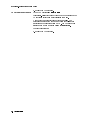
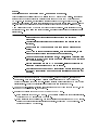
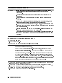
Overall Block Diagram of Color Display
Figure 4-2. Overall Block Diagram of Color Display
4-10 Troubleshooting
Display Troubleshooting
DANGER
These procedures require access to the interior of the color display,
only qualied service personnel should perform the servicing
procedures.
Use electrostatic discharge (ESD) precautions when performing any
servicing.
Do not touch the A4 power supply with your hands while power is
applied.
The A4 power supply has lethal voltages, with lethal currents, in all
areas for at least three minutes after power is turned o.
Use of a Ground Fault Interrupter (GFI), a Line-Isolated Variable Mains
Transformer (VARIAC), and extreme care are mandatory when servicing
the A4 power supply.
Service personnel must use a >>1 M
resistor-isolated wrist strap or
heel strap while handling the A4 power supply.
To avoid damaging the HP 70004A color display module connectors, the
HP 70004A color display must be o before installing or removing any
modules.
Display operation can be considered to fall into 13 categories, normal operation plus 12 failure
modes. Most of these can be quickly identied for troubleshooting. Several conditions require
removal of the instrument cover.
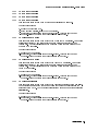
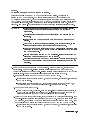
There are two banks of LEDs on the A5 processor. Each bank contains 10 LED segments.
These are located just behind the address switches (rear panel). By looking down and to the
left, through the fan, these LEDs may be observed. Adjacent to the LEDs is a second set of
DIP switches used for some diagnostic tests. (Refer to Figure 4-3.) The leftmost two LEDs in
each bank are used for status indicators. The rightmost eight in each bank are used to indicate
failures, or diagnostic results. In normal operation, the leftmost LED of A5DS2 is on, indicating
that the +5 V supply is working. Other LEDs are discussed in appropriate sections.
Troubleshooting 4-11
Figure 4-3. A5 Processor Diagnostics Location
The instrument can be conceptually divided into three parts: a power supply function, a
display function, and an HP-MSIB control function. With this division in mind, troubleshooting
can be performed sequentially, beginning with the power supply function. This procedure
is divided into three corresponding sections. If the power supply is known to be operating
properly, skip to the next section.
4-12 Troubleshooting
Diagnostic Tools
There are a number of diagnostic tools built into the color display to aid in troubleshooting.
These are described as follows:
A4 Power Supply Diagnostic Tools
Several indicators aid in determining the operating condition of the power supply. These are:
Front-Panel Lights
Internal Lights
Fan Operation
Module Operation
For descriptions of these tools, refer to \Troubleshooting the A4 Power Supply".
Display Diagnostic Tools, Turn-On
The display performs a number of diagnostic tests at turn-on.
Functions veried at turn on are:
HP-MSIB
ROM Checksums
RAM Checks
Keyboard Processor Checks
Graphics Processor
There are two modes of operation for the turn-on tests. These are controlled by the Test Mode
switch on the rear panel. In normal operation the Test Mode switch is o, and testing halts
on any failed test. Alternately, with the Test Mode switch set on, testing will continue past a
failed test.
If the Test Mode switch is not set (normal operation), and a failure occurs, operation halts. The
processor will display a display-disruptive error message on-screen. Also, the failure will be
encoded on A5DS2. (Refer to \If Display-Disruptive Errors Occur" for descriptions of the error
messages and the corresponding LED codes.)
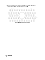
Display Diagnostic Tools, Front-Panel
The display also has several diagnostic tests which may be initiated from the front panel.
These are found by pressing misc , display tests . Four tests are available at this level:
Condence Test
Key Test
Knob Test
Tumbling Figures Demonstration
The Condence Test may be initiated by the user at any time. This is done using the misc ,
display tests , CONFID TEST softkeys, or by sending the HP-IB command TE. The two
methods cause identical testing to be done. The tests performed are:
Keyboard Processor
RAM Checks
Graphics Processor
Graphics Processor RAM (Pattern) Checksum
Displays the Character Set on Screen
NNNNNNNNNNNNNN
NNNNNNNNNNNNNNNNNNNNNNNNNNNNNNNNNNNNNNNNN
NNNNNNNNNNNNNN
NNNNNNNNNNNNNNNNNNNNNNNNNNNNNNNNNNNNNNNNN
NNNNNNNNNNNNNNNNNNNNNNNNNNNNNNNNNNN
Troubleshooting 4-13
The Key Test may be initiated by the user at any time. This is done using the misc ,
display tests , KEY TEST softkeys. This test allows each front panel key to be tested.
Detailed instructions are placed on the screen. Each key is veried by displaying a description
of the key pressed. The left arrow, or backspace, key is veried and then causes the test
program to exit.
The Knob Test may be initiated by the user at any time. This is done using the misc ,
display tests , KNOB TEST softkeys. This test places a circle on the screen, with a number
position centered. When the knob is turned, the circle rotates, and the center number either
increases or decreases, based on the direction the knob is turned. This allows the operation of
the knob to be veried. The test exits when a dierent activity is selected by the softkeys.
The Tumble Figures Demonstration, although usable at any time, may interfere with normal
MMS operation. It is accessed by pressing the misc , display test , TUMBLE FIGURES
softkeys. This demonstration exercises the graphics processor and is a good indication that it is
operating properly.
NNNNNNNNNNNNNN
NNNNNNNNNNNNNNNNNNNNNNNNNNNNNNNNNNNNNNNNN
NNNNNNNNNNNNNNNNNNNNNNNNNN
NNNNNNNNNNNNNN
NNNNNNNNNNNNNNNNNNNNNNNNNNNNNNNNNNNNNNNNN
NNNNNNNNNNNNNNNNNNNNNNNNNNNNN
NNNNNNNNNNNNNN
NNNNNNNNNNNNNNNNNNNNNNNNNNNNNNNNNNNNNN
NNNNNNNNNNNNNNNNNNNNNNNNNNNNNNNNNNNNNNNNNNNN
Display Diagnostic Tools, Failures
The display is capable of placing diagnostic messages on the screen for many dierent
problems. (Refer to \If Display-Disruptive Errors Occur".)
Should problems prohibit error messages from being displayed on screen, a number of tests
are built into the rmware to help identify the problem. The most common of these are
initiated by setting the rear panel test switch on and selecting the test, using the address
switches. Additional tests may be initiated using additional switches on the A5 processor. The
A5 processor has lights to indicate the results of the tests.
HP-MSIB Diagnostic Tools
The HP 70004A color display has two built-in HP-MSIB utilities. These utilities are accessed by
pressing the following keys:
4DISPLAY5
NNNNNNNNNNNNNN NNNNNNNNNNNNNNNNNNNNNNNNNNNNNNNNNNNNNNNNN NNNNNNNNNNNNNNNNNNNNNNNNNNNNNNNNNNNNNNNNN
Misc display tests service modes
The ACTIVE ON/OFF utility has two main softkeys: ACTIVE ON and ACTIVE OFF . These
softkeys send the HP-MSIB command to turn the active LED on any module in the system on
and o. This utility interferes with the normal system operation.
Once the command is sent, the display examines the HP-MSIB to see if the module received the
instruction. Use the following procedure to send the Active On command.
NNNNNNNNNNNNNNNNNNNNNNNNNNNNNNNNNNNNNNNNN
Note
NNNNNNNNNNNNNNNNNNNNNNNNNNNNN
NNNNNNNNNNNNNNNNNNNNNNNNNNNNNNNN
The Module Not Accepting Data message is returned for a master module if
one of its slaves has a faulty HP-MSIB interface. Therefore, verify that all of
the slaves of a master can communicate before determining that the master is
unable to communicate.
1. Press the ACTIVE ON softkey.
2. Using the numeric keypad, enter the row address of the module that is to be tested for an
HP-MSIB failure.
3. Press the ENTER softkey.
4. Enter the column address of the module as a hexadecimal number. Refer to Table 4-3 for
decimal-to-hexadecimal conversion information. Use the alphabetical softkeys and the
keypad to enter the hexadecimal numbers.
NNNNNNNNNNNNNNNNNNNNNNNNNNNNN
NNNNNNNNNNNNNNNNN
4-14 Troubleshooting
5. Press
ENTER .
NNNNNNNNNNNNNNNNN
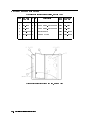
Table 4-3. Decimal/Hexadecimal Conversion
Decimal
Hexadecimal
Decimal
Hexadecimal
0
1
2
3
4
5
6
7
8
9
10
11
12
13
14
15
0
1
2
3
4
5
6
7
8
9
A
B
C
D
E
F
16
17
18
19
20
21
22
23
24
25
26
27
28
29
30
31
10
11
12
13
14
15
16
17
18
19
1A
1B
1C
1D
1C
1D
The HP-MSIB Utility key begins a utility for managing HP-MSIB directly. The HP-MSIB
utility is intended for use during the development of new modules. This utility interferes
with the normal system operation. Further descriptions of this utility and its softkeys are not
available.
NNNNNNNNNNNNNNNNNNNNNNNNNNNNNNNNNNNNNNNNNNNNNNN
Test Pattern Diagnostic Tools
The HP 70004A color display has built-in test pattern utilities for monitor adjustments and
troubleshooting. These utilities are accessed by pressing the following keys:
4DISPLAY5
NNNNNNNNNNNNNN NNNNNNNNNNNNNNNNNNNNNNNNNNNNNNNNNNNNNNNNN NNNNNNNNNNNNNNNNNNNNNNNNNNNNNNNNNNNNNNNNN
Misc display tests test patterns
Troubleshooting 4-15
Troubleshooting the A4 Power Supply
DANGER
These procedures require access to the interior of the color display,
only qualied service personnel should perform the servicing
procedures.
Use electrostatic discharge (ESD) precautions when performing any
servicing.
Do not touch the A4 power supply with your hands while power is
applied.
The A4 power supply has lethal voltages, with lethal currents, in all
areas for at least three minutes after power is turned o.
Use of a Ground Fault Interrupter (GFI), a Line-Isolated Variable Mains
Transformer (VARIAC), and extreme care are mandatory when servicing
the A4 power supply.
Service personnel must use a >>1 M
resistor-isolated wrist strap or
heel strap while handling the A4 power supply.
To avoid damaging the HP 70004A color display module connectors, the
HP 70004A color display must be o before installing or removing any
modules.
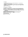
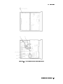
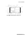
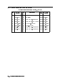
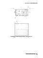
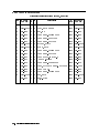
Troubleshooting the power supply involves inspection of fault indicators on the
A4 power supply. Several fuses are also accessed. See Figure 4-4 and Figure 4-5 for the
location of these components.
4-16 Troubleshooting
Figure 4-4. A4 Power Supply Indicators and Fuses (Front)
Troubleshooting 4-17
Figure 4-5. A4 Power Supply Indicators and Fuses (Back)
4-18 Troubleshooting
Potential A4 power supply failures may be categorized as follows:
State 1.
No Observed Power. The Front-Panel Indicator is o.
State 2.
The FAULT Indicator Light (A4DS6) is Lit.
State 3.
The I-LIMIT Fault Indicator Light (A4DS5) is Lit.
State 4.
Front-Panel LINE Indicator is O. Modules Have Power.
State 5.
Normal Operation Except Display is Blank.
State 6.
Front-Panel Indicators Normal, No Module Power.
Note
Some fault indicators may be eliminated by adjustments.
To dierentiate between some states, examination of internal indicators or voltage
measurements may be required. Only failures included in \State 1" may be addressed without
opening the instrument. If the rst statement does not match the instrument condition,
remove the instrument cover to dierentiate the other conditions.
The front panel LINE indicator is not on. Modules inserted into the display do not receive
power. (There is no voltage present at A4TP3 +5 VB. Refer to Figure 4-4 and Figure 4-5.) Go
to \State 1."
The front panel LINE indicator is not on. Modules inserted into the display do not receive
power. (The voltage is correct at A4TP3 +5 VB.) Go to \State 2" or \State 3."
The front panel LINE indicator is not on. Modules inserted into the display are receiving
power. Go to \State 4."
The front panel LINE indicator is not on. Operation seems to be normal, except the display is
blank. Go to \State 5."
The display front panel indicators are normal, but a module is not receiving power. Go to
\State 5."
Troubleshooting 4-19
State 1.
No Observed Power. The Front-Panel Power Indicator is O.
If the input voltage is 230 Vac, but the voltage selector switch is set for 115 Vac
Note
(see to Figure 4-6), the input fuse is blown at turn on, protecting the display.
Figure 4-6. Voltage Selector Switch
Use a line cord that is known to be good. Verify that the input line voltage is within limits and
that the display voltage selector switch setting agrees with the input line-voltage.
Note
After troubleshooting the display, always set the voltage selector switch to
match the user's input line-voltage. An incorrect voltage selector switch setting
will result either in too high an input voltage (blowing the ac line fuse) or too
low an input voltage (causing automatic shut-down with the internal FAULT
light on).
1. Check the ac line fuse, located on the rear panel. If the fuse is blown (open), replace it.
Then, verify the voltage selector switch is set correctly and turn on the display .
a. If the display starts working (the fan is turning, the green front panel line indicator light
is lit, and all fault indicator lights are o), the problem has been xed. If not, continue
with step 1b.
b. If the green front panel line indicator light is still o after checking or replacing the ac
line fuse, then turn o the display. Set the voltage selector switch to 115 Vac. Open the
instrument and access the A4 power supply.
DANGER
These procedures require access to the interior of the color display,
only qualied service personnel should perform the servicing
procedures.
Use electrostatic discharge (ESD) precautions when performing any
servicing.
Do not touch the A4 power supply with your hands while power is
applied.
The A4 power supply has lethal voltages, with lethal currents, in all
areas for at least three minutes after power is turned o.
4-20 Troubleshooting
Use of a Ground Fault Interrupter (GFI), a Line-Isolated Variable Mains
Transformer (VARIAC), and extreme care are mandatory when servicing
the A4 power supply.
Service personnel must use a >>1 M
resistor-isolated wrist strap or
heel strap while handling the A4 power supply.
To avoid damaging the HP 70004A color display module connectors, the
HP 70004A color display must be o before installing or removing any
modules.
2. Connect the isolated output of the Line-Isolated Variable Mains Transformer (VARIAC) to the
display's input. Turn the Line-Isolated Variable Mains Transformer (VARIAC) on and adjust
its output to 115 Vac.
Observe the A4DS1 HV neon indicator light (see Figure 4-4 and Figure 4-5):
If A4DS1 HV is o, then unplug the line cord and recheck the ac line fuse. If the fuse
is blown (open), continue with step 2a. If the fuse is good, check the ac input to the
A4 power supply and the output of the A4S1 on/o. (The output of A4S1 is checked
between A4E1 and A4E2, using the leads closest to A4S2, the 120/240 Line Select switch.)
If these points show 115 Vac, replace the A4 power supply otherwise, replace the failed
component. Continue with step 3.
If A4DS1 HV is on, and all other fault indicator lights are o, check the voltage between
A4TP3 +5 VB and A4TP2 COM for 5 Vac 60.25 V. (Refer to Figure 4-4.) If the voltage at
A4TP3 is good, continue with 2c.
a. If the ac line fuse is blown (open), then something is shorting the ac input voltage. First,
check the ac input cable plugged into A4P2. If it is oset by one pin (on either side) the
input will be shorted to ground and the ac line fuse will blow. Replace the fuse, then
continue with step 3. Second, check the line module and cable (FL1) by applying power
with the cable disconnected from the power supply. If FL1 is faulty, replace it, then
continue with step 3.
If no problem has been identied, the A4 power supply has failed. Replace the
A4 power supply, and continue with step 3.
b. If the voltage at A4TP3 is bad, then turn the Line-Isolated Variable Mains Transformer
(VARIAC) o. Wait one minute after A4DS1 HV goes out. Remove and check the A4F2
Bias Fuse (see Figure 4-4).
If the A4F2 fuse is blown (open), then replace the fuse. Turn the Line-Isolated Variable
Mains Transformer (VARIAC) on. If the power supply indicator lights are now NORMAL
with the fan running, continue with step 3. If the power supply is not operating
normally, turn the Line-Isolated Variable Mains Transformer (VARIAC) o. Wait one
minute after A4DS1 HV goes out, replace the A4 power supply, then continue with
step 3.
If the A4F2 fuse is good, the failure is likely to be in the bias supply. For assembly
level support, replace the A4 power supply and continue with step 3.
c. If the voltage at A4TP3 is good, and all fault indicators are o, the failure is likely in the
switching regulator circuit. Turn the Line-Isolated Variable Mains Transformer (VARIAC)
o and wait one minute after A4DS1 HV goes out. Replace the A4 power supply, and
continue with step 3. (Refer to the \Component-Level Hints".)
3. If the display starts working (the fan is turning, the green front panel line indicator light is
lit, and all fault indicator lights are o), the problem has been xed. Reassemble the display.
Troubleshooting 4-21
If the problem is not xed, a troubleshooting clue was missed and more thorough
troubleshooting is required.
4-22 Troubleshooting
State 2.
The FAULT Indicator Light (A4DS6) is Lit.
Some fault indicators may be eliminated by adjustments.
Note
To determine if this is the correct state to troubleshoot, remove the instrument cover. Refer to
Figure 4-4 and Figure 4-5 for the location of the test points and indicators discussed below.
Verify that the voltage at A4TP3 is approximately 5 V. If it is not, return to \State 1."
If the indicator labeled I LIMIT is on, skip to \State 3."
If the indicator labeled FAULT is on, proceed with \State 2."
A4DS6 FAULT indicator light indicates that a fault has occurred and the A4 power supply
has turned o its output to protect both itself and any modules resident in the display. Five
conditions can cause the FAULT indicator to light.
If the internal temperature rises too high, the display will protect itself and the modules
from overheating by shutting down. This temperature is set to trip if the ambient
temperature surrounding the display exceeds 55 C. This is not a failure. To allow the
display's internal temperature to cool down move the display into a cooler environment and
wait at least 20 minutes before turning it back on. The display should now operate correctly.
The internal temperature may also rise if the air inlet is blocked, or the fan has failed. Check
the air inlet for blockage. If the FAULT light is still on, continue with step 1.
Low ac input voltage to the display. Check the voltage selector switch setting (see Figure 4-6)
on the bottom cover. The switch setting must be either 115 Vac for 87 to 132 Vac input or
230 Vac for 174 to 264 Vac input. If the line-voltage does not meet specication, then the
display is probably good. Connect the display to a good line-voltage source and verify its
operation. If the voltage selector switch setting is incorrect, unplug the line cord, then
change the setting. The display should now operate correctly.
The A4 power supply output voltage to the fan is protected by the A4F702 +12 V fuse (see
Figure 4-4). If A4F702 is blown (open), the A4DS6 FAULT indicator will light.
The +5 Vdc supply current supplied by the A4 power supply is monitored. If too much
current is drawn by the display, the power supply will shut down and the A4DS6 FAULT
indicator will light.
If the display's 40 kHz output exceeds its maximum voltage specication by 30%, the display
will shut down.
Troubleshooting 4-23
DANGER
These procedures require access to the interior of the color display,
only qualied service personnel should perform the servicing
procedures.
Use electrostatic discharge (ESD) precautions when performing any
servicing.
Do not touch the A4 power supply with your hands while power is
applied.
The A4 power supply has lethal voltages, with lethal currents, in all
areas for at least three minutes after power is turned o.
Use of a Ground Fault Interrupter (GFI), a Line-Isolated Variable Mains
Transformer (VARIAC), and extreme care are mandatory when servicing
the A4 power supply.
Service personnel must use a >>1 M
resistor-isolated wrist strap or
heel strap while handling the A4 power supply.
To avoid damaging the HP 70004A color display module connectors, the
HP 70004A color display must be o before installing or removing any
modules.
1. Remove the cover and access the A4 power supply. With the Line-Isolated Variable Mains
Transformer (VARIAC) turned o, connect its isolated output to the display's input.
2. Verify the display's voltage selector switch setting (115 Vac).
3. Remove and check fuse A4F702.
a. If fuse A4F702 is good, insert the fuse, turn the Line-Isolated Variable Mains Transformer
(VARIAC) on, and check to see if the fan B1 is operating. (The instrument should be cool
to prevent an over-temperature condition from looking like another problem.) If the fan
does not run, the FAULT indicator is not on, and the instrument appears to be operating
normally, verify that the B1 Fan Assembly is plugged in. If the fan still does not run,
replace the fan assembly. Otherwise, go to step 4.
b. If A4F702 is open, replace it. A faulty external HP-HIL device could cause this problem,
remove any external HP-HIL devices which may be connected to the display. Turn the
Line-Isolated Variable Mains Transformer (VARIAC) on and adjust its output to 115 Vac. If
removing the external HP-HIL device xes the display (indicators in the NORMAL state)
then reassemble the display. The external HP-HIL device requires repair. This is not a
display failure.
c. If the A4F702 fan fuse is blown (open) again, then the fan may be shorting this output.
Turn the Line-Isolated Variable Mains Transformer (VARIAC) o. Wait one minute after
A4DS1 HV goes out, then disconnect the fan connector from A5J9 on the A5 processor.
Replace A4F702 and turn the Line-Isolated Variable Mains Transformer (VARIAC) on. If
the FAULT indicator is lit, turn o power, and wait 1 minute after A4DS1 HV goes out,
then replace the A4 power supply and reassemble the display. If the FAULT indicator
light (A4DS6) stays o, turn the Line-Isolated Variable Mains Transformer (VARIAC) o.
Replace the fan. All the indicators should be in their normal state with the fan running.
If no other errors are present, reassemble the display.
4. If the A4DS6 FAULT indicator remains lit, the problem is either on the A4 power supply or
too much current is being drawn from the +5 Vdc supply.
a. With the Line-Isolated Variable Mains Transformer (VARIAC) turned o, disconnect the
W3 ribbon cable from the A4P1 connector. Turn on the Line-Isolated Variable Mains
4-24 Troubleshooting
Transformer (VARIAC) and check the A4DS6 FAULT indicator to see if the supply is now
working.
b. If the supply is now working, the problem is likely a short on one of the assemblies
using the +5 Vdc supply. Isolate the fault to the A5 processor, the A6 HP-MSIB or the
A2 interface by connecting them one at a time.
c. If the supply is still not working, the problem is likely in the switching power supply.
Additional troubleshooting information is located in the \Component-Level Hints".)
Replace the A4 power supply and reassemble the display. The display should now be
repaired.
Troubleshooting 4-25
State 3.
The I LIMIT Fault Indicator Light (A4DS5) is Lit.
Some fault indicators may be eliminated by adjustments.
Note
To determine if this is the correct state to troubleshoot, remove the instrument cover. Refer to
Figure 4-4 and Figure 4-5 for the location of test point and indicators discussed below.
Verify that the voltage at A4TP3 is approximately 5 V. If it is not, return to \State 1."
If the indicator labeled FAULT is lit, return to \State 2."
If the indicator labeled I LIMIT is lit, proceed with \State 3."
The display's 40 kHz output is overloaded (too much current), causing the A4 power supply to
shut down to prevent damage to itself.
DANGER
These procedures require access to the interior of the color display,
only qualied service personnel should perform the servicing
procedures.
Use electrostatic discharge (ESD) precautions when performing any
servicing.
Do not touch the A4 power supply with your hands while power is
applied.
The A4 power supply has lethal voltages, with lethal currents, in all
areas for at least three minutes after power is turned o.
Use of a Ground Fault Interrupter (GFI), a Line-Isolated Variable Mains
Transformer (VARIAC), and extreme care are mandatory when servicing
the A4 power supply.
Service personnel must use a >>1 M
resistor-isolated wrist strap or
heel strap while handling the A4 power supply.
To avoid damaging the HP 70004A color display module connectors, the
HP 70004A color display must be o before installing or removing any
modules.
1. First, remove all the modules. Turn the display on and verify operation. If the display
I LIMIT light is still on, continue with step 2. If the I LIMIT light is no longer on, turn o the
display and install each module one at a time (cycling power after installing each module)
to locate the faulty module. Remove the rst module and install the second, and so on. If,
after replacing each module, the I LIMIT light is o, check the I LIMIT trip point.
2. Disconnect the W3 ribbon cable from the A4P1 connector. Refer to Figure 4-4. Verify that
the display's voltage selector switch is set to 115 Vac. Refer to Figure 4-6. Connect the
isolated output of the Line-Isolated Variable Mains Transformer (VARIAC) to the display's
input. Turn the Line-Isolated Variable Mains Transformer (VARIAC) on and adjust the
Line-Isolated Variable Mains Transformer (VARIAC)'s output to 115 Vac.
a. If the I LIMIT indicator (A4DS5) is still on, turn the Line-Isolated Variable Mains
Transformer (VARIAC) o, and wait one minute after A4DS1 HV goes out. Replace the
A4 power supply. The power supply should be operating normally (the fan turning and
fault indicators o). Reassemble the display.
4-26 Troubleshooting
b. If the I LIMIT indicator (A4DS5) is o and the power supply begins operating, verify the
voltages between the following test points:
A4TP24 +65V to A4TP25 +65VR
A4TP26 +5VS to A4TP27 +5VRS
A4TP23 +18V to A4TP29 +12VR
A4TP28 +12V to A4TP29 +12VR
A4TP22 012V to A4TP29 +12VR
If the voltages are within 65%, a short probably exists on one or more of the following:
the W3, the A5 processor, the A6 HP-MSIB, or the A2 interface. Turn the Line-Isolated
Variable Mains Transformer (VARIAC) o.
Note
When the faulty assembly has been identied and replaced, check the
operation of the power supply. If the power supply operates normally (the fan
is turning and the fault indicators are o), reassemble the display.
3. The other assemblies should be connected to the power supply one at a time. In this
manner, the I LIMIT fault indicator will help to identify the faulty assembly. Be certain to
turn o the display before each step. Connect the components and monitor A4DS5 in the
following order:
a. Connect the W3 ribbon cable into the A4P1 Connector without the the A5 processor
connected.
b. Turn o the Line-Isolated Variable Mains Transformer (VARIAC) and connect the
A5 processor.
c. Connect the A1 front panel to the A5 processor.
d. Connect the A2 interface to the A5 processor.
e. Connect the B1 Fan Assembly to the A5 processor.
f. Connect the A3 monitor/monitor bracket to the A5 processor.
g. Connect the A6 HP-MSIB to the A5 processor.
Replace the assembly which caused the A4DS5 I LIMIT indicator to light. If A4DS5 stays o,
then continue with step 4.
4. If the A4DS5 I LIMIT light is still o after performing the procedure outlined in step 3, then
the likely problem is a mechanical interference between a conductive point on one of the
assemblies with the display chassis. Check the W3 ribbon cable for any visible damage
(pinching) caused by the sheet metal. The display should now operate normally without the
A4DS5 I LIMIT light on. Reassemble the display.
Troubleshooting 4-27
State 4.
Front-Panel LINE Indicator is O. Modules Have Power.
This condition is most likely caused by a failure in the 5 V supply of the display. This supply
is connected to the front panel LINE indicator and is used by both the A5 processor and
A6 HP-MSIB. In this state, any installed modules should have power, but since the HP-MSIB
will not be functioning, the error (ERR) indicator on each module should blink. The I/O light or
HP-MSIB light of any mainframes or other displays connected in the system should be on.
A low voltage state of the 5 V supply may cause the front panel HP-MSIB indicator to be on.
In this state HP-MSIB will be in a reset condition, and all modules should keep all front panel
indicators on.
DANGER
These procedures require access to the interior of the color display,
only qualied service personnel should perform the servicing
procedures.
Use electrostatic discharge (ESD) precautions when performing any
servicing.
Do not touch the A4 power supply with your hands while power is
applied.
The A4 power supply has lethal voltages, with lethal currents, in all
areas for at least three minutes after power is turned o.
Use of a Ground Fault Interrupter (GFI), a Line-Isolated Variable Mains
Transformer (VARIAC), and extreme care are mandatory when servicing
the A4 power supply.
Service personnel must use a >>1 M
resistor-isolated wrist strap or
heel strap while handling the A4 power supply.
To avoid damaging the HP 70004A color display module connectors, the
HP 70004A color display must be o before installing or removing any
modules.
1. Remove the cover and access the A4 power supply. Refer to Chapter 4, \Replacement
Procedures." With the Line-Isolated Variable Mains Transformer (VARIAC) turned o,
connect the isolated output of the Line-Isolated Variable Mains Transformer (VARIAC) to the
display's input. Verify the display's voltage selector switch setting (115 Vac).
2. Turn on the Line-Isolated Variable Mains Transformer (VARIAC) and set it to 115 Vac. If the
A4DS6 FAULT indicator is lit, go to State 2.
3. Measure the voltage between A4TP26 +5VS and A4TP27 +5VRS.
a. If the voltage is between 4.75 V and 5.2 V, the problem is likely the front panel indicator.
Verify that the +5 V indicator on A5DS2 is on.
b. If the voltage is out of tolerance, a component failure has occurred in the +5 Vdc supply.
Unless component level troubleshooting is necessary, replace the A4 power supply. The
problem should now be corrected.
4-28 Troubleshooting
State 5.
Normal Operation Except Display is Blank.
This state normally means the +65 V power supply is not working. This supply is
located on the A4 power supply. The supply passes through the A5 processor to the
A3 monitor/monitor bracket. The A5 processor is capable of shutting down (turning o) the
+65 V supply. Any keystroke turns the +65 Vdc back on. This should be done rst to insure
the problem is hardware. Allow at least one minute for the monitor to warm up. Refer to
Figure 4-4 and Figure 4-5 for the location of the test points and indicators discussed below.
DANGER
These procedures require access to the interior of the color display,
only qualied service personnel should perform the servicing
procedures.
Use electrostatic discharge (ESD) precautions when performing any
servicing.
Do not touch the A4 power supply with your hands while power is
applied.
The A4 power supply has lethal voltages, with lethal currents, in all
areas for at least three minutes after power is turned o.
Use of a Ground Fault Interrupter (GFI), a Line-Isolated Variable Mains
Transformer (VARIAC), and extreme care are mandatory when servicing
the A4 power supply.
Service personnel must use a >>1 M
resistor-isolated wrist strap or
heel strap while handling the A4 power supply.
To avoid damaging the HP 70004A color display module connectors, the
HP 70004A color display must be o before installing or removing any
modules.
1. Remove the cover and access the A4 power supply. Refer to Chapter 4, \Replacement
Procedures." With the Line-Isolated Variable Mains Transformer (VARIAC) turned o,
connect the isolated output of the Line-Isolated Variable Mains Transformer (VARIAC) to the
display's input. Verify the display's voltage selector switch setting (115 Vac).
a. Measure the voltage between A4TP24 +65V and A4TP25 +65VR.
If this voltage is not approximately 65 V, refer to Chapter 2, \Adjustments," or replace
the A4 power supply.
If this voltage is approximately 65 V, the problem is either the ribbon cable W3, the
A5 processor or the A3 monitor/monitor bracket. Continue with step 3.
b. Remove and check fuse A4F701.
If fuse A4F701 is open, replace it. Turn the Line-Isolated Variable Mains Transformer
(VARIAC) on and adjust its output to 115 Vac. If replacing the A4F701 fuse xes the
display (indicators in the NORMAL state) then reassemble the display.
c. If fuse A4F701 is blown (open) again, then the display may be shorting this supply. Turn
the Line-Isolated Variable Mains Transformer (VARIAC) o. Wait one minute after A4DS1
HV goes out, then replace A4F701 and disconnect the ribbon cable W3 from A4P1. Turn
on the display and measure the voltage between A4TP24 +65V and A4TP25 +65VR.
If this voltage is not approximately 65 V, refer to Chapter 2, \Adjustments," or replace
the A4 power supply.
Troubleshooting 4-29
If this voltage is approximately 65 V, the problem is either the ribbon cable W3, the
A5 processor or the A3 monitor/monitor bracket. Continue with step 3.
d. There is either a short or an open in the +65 Vdc system. To isolate the faulty assembly,
disconnect W3, A5 processor, W4, and A3 monitor/monitor bracket. Reconnect W3,
A5 processor, W4, and A3 monitor/monitor bracket one at a time, check A4F701 or the
voltage between A4TP24 +65V and A4TP25 +65VR. Verify the output voltage of the
assembly just connected is approximately 65 V. Replace the faulty assembly.
4-30 Troubleshooting
State 6.
Front-Panel Indicators Normal, No Module Power.
The display supplies the power requirements of the modules. This state presumes that the
40 kHz supply is working, because the front panel indicators are normal. The front panel LINE
indicator is powered by the +5 V supply, which is derived from the 40 kHz system.
The 40 kHz power is generated on the A4 power supply. It is routed out connector A4P1,
through W3 ribbon cable, to the A5 processor, coming in on connector A5J1. The A5 processor
passes the power directly to the A6 HP-MSIB Interconnect Assembly, leaving through A5J5,
entering through A6J7.
At power-up, all module front panel LEDs turn on, then o, indicating that the module has
input power. If a module's LEDs do not ash, then the slot that contains the module may be
bad (no 40 kHz power).
DANGER
These procedures require access to the interior of the color display,
only qualied service personnel should perform the servicing
procedures.
Use electrostatic discharge (ESD) precautions when performing any
servicing.
Do not touch the A4 power supply with your hands while power is
applied.
The A4 power supply has lethal voltages, with lethal currents, in all
areas for at least three minutes after power is turned o.
Use of a Ground Fault Interrupter (GFI), a Line-Isolated Variable Mains
Transformer (VARIAC), and extreme care are mandatory when servicing
the A4 power supply.
Service personnel must use a >>1 M
resistor-isolated wrist strap or
heel strap while handling the A4 power supply.
To avoid damaging the HP 70004A color display module connectors, the
HP 70004A color display must be o before installing or removing any
modules.
1. If the display fan is turning, or the display is working, but one of the modules is not
receiving power, move that module to a dierent slot. If moving the module to a dierent
slot corrects the problem, verify that there was not a connector-mating or alignment
problem, by placing the module back to the original slot. If the original slot still does not
provide power, replace the A6 HP-MSIB Interconnect Assembly. The display should now
operate correctly.
2. If moving the module to another slot does not correct the problem, install a known good
module in the slot. If the known good module receives power, then the rst module requires
repair. This is not a display failure.
3. If the display fan is turning, but none of the module front panel LEDs turn on and
any possible connector-mating problems have been identied. Either the A6 HP-MSIB
Interconnect Assembly or the A5 processor has failed.
a. Remove the cover and access the A4 power supply. Refer to Chapter 4, \Replacement
Procedures." With the Line-Isolated Variable Mains Transformer (VARIAC) turned o,
connect the Line-Isolated Variable Mains Transformer (VARIAC)'s isolated output to the
display's input. Dangerous voltages exist on the power supply board assembly. Do not
Troubleshooting 4-31
touch the power supply while power is applied. Verify the display's voltage selector
switch setting (115 Vac).
b. Using a DVM, check the voltage between pins 37/39 and 38/40 on A5J5 for a reading of
approximately 27 Vac.
c. If the voltage on A5J5 is good, the problem is likely on the A6 assembly. This can be
veried by checking the continuity between the corresponding pins of A6J7 and the pins
on each of A6J3 through A6J6. Replacing the A6 assembly should correct the problem.
d. If the voltage on A5J5 is bad, verify that the voltage on A5J1 is approximately 27 Vac
(between pins 3/4/5/6/15/16/17/18 and pins 9/10/11/12/21/22/23/24). These pins are
labeled AC A and AC B on the schematic. If the voltage is good, the problem is the
A5 processor. If the voltage is bad, suspect the ribbon cable W3. Check the voltage
between A4P1{3/4/5/6/15/16/17/18 and A4P1{9/10/11/12/21/22/23/24). By this point,
sucient isolation should have identied the failed assembly.
Component-Level Hints
The purpose of this service manual is to facilitate assembly-level repair. There may be times
when assembly-level is not sucient. In these cases, the following basic information may help.
The main power supply is a switching supply. These circuits are generally complex, and the
HP 70004A color display is no exception. Troubleshooting switching supplies can be very
dicult. The following are functional groups of supplies which are more straightforward
to troubleshoot. (Refer to Figure 4-4 and Figure 4-5 for the location of the test points and
indicators discussed below.)
The pulse modulator controls the switching supply. If A4DS6 FAULT indicator is lit, and the
problem is known to be on the A4 power supply, the following steps should identify if the
pulse modulator is working correctly.
a. Turn o the Line-Isolated Variable Mains Transformer (VARIAC), wait one minute after
A4DS1 HV goes out, then remove the A4F1 service fuse.
b. Connect an oscilloscope probe between test points A4TP17 PW and A4TP16 COM. (Refer
to Figure 4-3.) Set the scope to 2 s/Div and 1 V/Div.
c. Turn the Line-Isolated Variable Mains Transformer (VARIAC) on and set it to 115 Vac.
Observe the waveform at A4TP17 PW. The signal should be narrow pulses about 12.5 s
apart (approximately six divisions), and about 5 V in amplitude.
The switching supply depends on the bias supply. This conventional supply rst starts by
receiving power from the line-through transformer A4T1 and A4F2. Once the switching
supply is working, the +15 Vdc supply is derived from the switching supply through
transformer A4T2 and A4F3. The +5 Vdc bias supply is generated from the +15 Vdc bias
supply.
The +65 Vdc supply has a dedicated secondary winding on transformer A4T2. It is protected
by fuse A4F701. The series-pass element is transistor A4Q703, and the regulation circuit
is not unusual. It is possible for the processor to shut down the +65 Vdc supply through
control line +65V SHT DWN.
The 40 kHz output, +5 Vdc, and 612 Vdc supplies share the same secondary winding on
transformer A4T2. The traditional +5 Vdc supply is regulated by A4U702 and series-pass
element A4Q704.
The 12 V supplies are simple lter supplies for the fan. They are protected by fuse A4F702,
which when blown shuts down the switching supply through A4U70 and control line
+12V SHT DWN. When shut down, the FAULT indicator will light.
4-32 Troubleshooting
Display and Processor Troubleshooting
This section is to assist with determining which assembly, the A3 monitor/monitor bracket or
the A5 processor, needs replacing. It is assumed that all power supplies are working properly.
Some additional information is provided to assist in component-level troubleshooting of the
A5 processor. There are no eld-serviceable parts in the A3 monitor/monitor bracket.
Potential display and processor failures may be categorized as below:
State 7.
Display-Disruptive Message.
State 8.
Abnormal CRT Display.
State 9.
Memory Card Troubleshooting.
Identifying the Failed Assembly
The built-in turn-on diagnostics should be sucient to identify any failure in the A5 processor.
Unfortunately, if the A3 monitor/monitor bracket has failed, there is no front panel indication
as to the location of the problem. The following steps should be helpful.
State 7.
Display Disruptive Messages.
If there is a display-disruptive message on the screen, follow the instructions displayed (refer
to \If Display-Disruptive Errors Occur"). Generally, when one of these messages appears, the
A5 processor has a failure. However, it is still operating suciently to diagnose itself and
communicate the problem.
State 8.
Abnormal CRT Display.
1. If the screen is blank, and an external monitor (use the HP 35741A multisync PLUS or
HP 35741A multisync XL, is available, connect it to the rear panel connections. The
indication on the external monitor should be sucient to determine which assembly is at
fault.
2. During the turn-on tests, the processor displays each step of the testing on the two on-board
displays, A5DS1 and A5DS2. If the lights do not blink during this time, the processor is
defective. Replace the A5 processor.
3. Following the turn-on tests, the processor will indicate via A5DS2 which test failed. Set
the rear panel Test Mode switch to the normal position. Turn on the instrument and
allow the turn-on sequence to nish. Observe the A5 processor diagnostic LEDs. All eight
fault LEDs of A5DS2 should be o. See Figure 4-3. If any of these LEDs are lit, refer to
the \Display-Disruptive" section in this chapter for LED pattern denitions and repair
instructions.
4. If none of the above steps identies a problem with the A5 processor, replace the
A3 monitor/monitor bracket.
Troubleshooting 4-33
State 9.
Memory Card Troubleshooting.
Memory Card information is controlled by the A5 processor. The A2 interface provides a path
for control and data signals, plus the connector for the Memory Card.
1. Press 4Display5, 4Mass Storage5, 4MSI5, and 4Memory Card5.
The amber light next to the memory card slot should blink.
If the red light is on, then the battery in the memory card needs to be replaced.
If the message \Unable to read device" is reported, then the memory card is not initialized
or is not all the way inserted.
2. Verify the Memory Card is good by trying the suspect card in another instrument. If the
card is good, proceed with step 2. If the card is the identied problem, replace the card.
3. Inspect the memory card connector for damage. If the connector is damaged, replace the
A2 interface.
4. If no other problem is identied, replace the A5 processor. This should correct the problem.
A5 Processor Component-level Troubleshooting
Although specic troubleshooting instructions are not included for component-level repair, the
following information on built-in tests is valuable, should this level of repair be required.
There are two groups of tests. The rst is called \Select Mode Tests." These are selected by the
address switches on the rear panel. The results may be seen on A5DS2 through the fan. The
second group is called \Service Tests." These require access to the second bank of switches
located on the A5 processor.
Select Mode Tests
These tests are used with address switch settings. They allow a set of individual diagnostic
tests to be run with a minimum of processor functionality. They are intended to assist in
verifying operation of specic processor blocks and help isolate faults.
These tests do not require removing the display system cover. The A5DS2 LEDs may be seen
through the fan air inlet. After selecting a test mode (A5S1 ADDR SW), start the test by
cycling the power. When the test begins, the test number is displayed on A5DS2.
If the test fails, the failure is indicated on A5DS2 as listed in Table 4-4 if ran in \Halt Mode."
The test number may be changed to select a dierent test without re-cycling power if the
previous test has not failed in the \Halt Mode."
CAUTION
Some of these tests are destructive to stored system states, such as window
denitions stored in non-volatile RAM and the real time-clock settings.
4-34 Troubleshooting
A5S1 ADDR SW:
0NNNN101
CONTINUE MODE:
0NNNN111
HALT MODE:
Does not display error message, repeats test
continuously. LEDs ash once per completion
of test loop. If the display system functions,
the test name is displayed in block letters on
the monitor and re-written once per
completion of test loop.
Displays error message, halts test on error.
LEDs display error code. LEDs ash once per
completion of test loop. If the display system
functions, the test name is displayed in block
letters on the monitor and re-written once per
completion of test loop. If the test fails, an
error message is displayed with instructions
for restart.
The following table lists each of the Select Mode Tests. The test number shown is used in
place of the NNNN in the A5S1 ADDR SW setting. Also shown is the two indications possible on
A5DS2. The rst shows the test number. The second shows the indication when the test fails.
Test
Number
0
1
2
3
4
5
6
7
8
9
10
0000
0001
0010
0011
0100
0101
0110
0111
1000
1001
1010
11
12
13
14
15
1011
1100
1101
1110
1111
Tests:
Table 4-4. Select Mode Tests
Test Number:
LEDs
ROM Checksum
CMOS RAM Data
CMOS RAM Address
Slave Processor 8041
DRAM Address
VRAM Address
HP-MSIB
HP-HIL 8042
Real Time Clock
Memory Card LED
Check
No Test
No Test
No Test
No Test
No Test
LED Test Code: ON = NA
Fail Code:
NA
FLASH
FLASH
FLASH
FLASH
FLASH
NA
NA
NA
NA
NA
NA
OFF = Troubleshooting 4-35
Table 4-5 lists the description of each of the Select Mode Tests. The test number shown is used
in place of the NNNN in the A5S1 ADDR SW.
Table 4-5. Test Descriptions
Name
Test
Number
0
0000
LEDs
1
2
0001
0010
ROM Checksum
CMOS RAM Data
3
0011
CMOS RAM Address
4
0100
Slave Processor 8041
5
0101
DRAM Address
6
0110
VRAM Address
4-36 Troubleshooting
Description
To visually verify LED operation, segments of
the LED displays, A5DS1 and A5DS2, are
ashed alternately on and o. (LEDs ash
even, odd, all, and none.) No internal
verication is performed.
The checksum is veried for each of the ROMs.
For each location in CMOS RAM (with the
exception of the non-volatile variable area), a
1 is cycled through all 16 locations on the data
bus. Each time a word is written, it is read
back and checked. The test should nd any
shorted or open data lines. Each word is
saved before testing, and then restored to
allow the test to be non-destructive.
An address register is increased by one
(increment) as a data pattern is decreased by
one (decrement). The processor then reads
and veries each location.
This test tells the 8041 processor to send a
count sequence to the host processor, which if
received correctly, should verify the 8041
processor and the link to it.
An address register is increased by one
(increment) as a data pattern is decreased by
one (decrement). The processor then reads
and veries each location.
An address register is increased by one
(increment) as a data pattern is decreased by
one (decrement). The processor then reads
and veries each location.
Test
Number
Table 4-5. Test Descriptions (continued)
Name
Description
7
0111
HP-MSIB
8
1000
HP-HIL 8042
9
1001
Real Time Clock
10
1010
Memory Card LED Check
The functions performed are: send a NULL to
Address 31 and check for NMAA (No Module At
Address),which is the expected response.
Send 0, 1, 2, 4, 8, 16, 64, 128 to self and
check the data after each is sent. The most
likely cause of a failure of this test is the
HP-MSIB itself is hung (backplane error), that
some line is short or open, that the display's
HP-MSIB chip has failed or that the host's
interface to the HP-MSIB chip has failed.
The 8042 status and data registers are read to
verify its power-up initialization has
completed successfully.
The Real Time Clock seconds register is read
to verify that it is incrementing.
Any memory card must be removed. The test
alternately ashes the red \BAT" and yellow
activity indicators.
Troubleshooting 4-37
Service Tests
These tests are intended to assist in component-level fault isolation. They require the display
system cover to be removed and the processor board be placed into the service position to
allow system operation and access to the component side of the board.
DANGER
CAUTION
These procedures require access to the interior of the color display,
only qualied service personnel should perform the servicing
procedures.
Use electrostatic discharge (ESD) precautions when performing any
servicing.
Do not touch the A4 power supply with your hands while power is
applied.
The A4 power supply has lethal voltages, with lethal currents, in all
areas for at least three minutes after power is turned o.
Use of a Ground Fault Interrupter (GFI), a Line-Isolated Variable Mains
Transformer (VARIAC), and extreme care are mandatory when servicing
the A4 power supply.
Service personnel must use a >>1 M
resistor-isolated wrist strap or
heel strap while handling the A4 power supply.
To avoid damaging the HP 70004A color display module connectors, the
HP 70004A color display must be o before installing or removing any
modules.
Some of these tests are destructive to stored system states, such as window
denitions stored in non-volatile RAM and the real time-clock settings.
With the A5 processor board schematic and a two channel oscilloscope, signals are examined to
locate the failed component. The test routines use a minimum of hardware and instructions to
allow low-level fault isolation. The routines loop continuously with short cycle times to allow
the oscilloscope to trigger and display the complete loop with practical sweep times.
All tests are started from the reset state. The test code is set on A5S1 and A5S2, then A5S4 is
pressed and released to start the test.
Each of the tests in this section require the processor kernel to be operating. If a problem is
suspected in the kernel, the following test should be performed.
Free Run Test
1. Place the A5 processor with the circuit side down.
2. With power turned o, remove jumper A5U9.
3. Turn on power. The processor should now receive a command that causes it to increment
through its entire address range.
4. Using an oscilloscope and the schematic, verify each of the address lines. The address lines
should be toggling, with each successive higher address line at one-half the frequency of the
previous lower line.)
5. Using an oscilloscope and the schematic, verify the address decoding (A5U109, A5U82, and
A5U83) and read strobe logic.
4-38 Troubleshooting
6. If the above steps are good, the processor kernel is functioning properly without the ROMs.
The ROM Checksum Select Mode Test will help verify proper ROM operation.
Troubleshooting LEDs and DIP Switch Map
The two 8 bit dip switches allow manual input of test codes and data. A5DS1 and A5DS2, ten
segment LED displays (see Figure 4-7), are used to indicate test status and data. The RST push
button switch, A5S4, allows the processor board to be reset to a power-up condition without
cycling power. A5S4 does not reset the HP-MSIB board, modules, or external systems. If the
HP-MSIB board is not plugged into the processor board, A5S4 must be pressed to reset the
processor board.
To initiate the Service Tests, set both A5S1 (Address Switch) and A5S2 to the appropriate
positions. See Figure 4-8. Press and release the A5S4 RST switch. The switches (A5S1 and
A5S2) are now available to enter data for the test as required. To initiate another test, A5S1
and A5S2 must be set and then A5S4 RST pressed again.
Figure 4-7. A5 Processor Diagnostics Locations
Troubleshooting 4-39
Figure 4-8. A5 Processor Switch Locations
4-40 Troubleshooting
Service Test List
Group 0
A5S1 ADDR SW:
110001X1
Group 0:
A5S2 UPPER SW:
11111111
Test 0:
11111110
1111110X
Test 1:
Test 2:
111110XX
11110XXX
Test 3:
Test 4:
1110XXXX
Test 5:
110XXXX0
Test 6:
10XXXXX0
Test 7:
RAM strobes, RAM tests, External bus tests, Real Time Clock test,
RAM and Real Time Clock battery backup tests.
RAM strobes. Upper and lower byte write, word write, and word
read.
RAM data. Rotate bit pattern through RAM.
RAM address. Write unique pattern to each location, test and
write to LEDs.
RAM data. Read dip switch, write to RAM. Test and loop on error.
External bus read and write strobes. Write and read to each
address rotating data bit.
Real Time Clock. Initialize to 12/31/99, 23:59:50. In ten
seconds all registers should roll over. Total value of registers is
displayed on LEDs.
RAM battery backup. Initializes RAM with unique data in each
address, waits for power cycle and bit 8 on dip to be set (A5DS2
110XXXX1) to test RAM data.
Real Time Clock battery backup. Initializes Real Time Clock as in
test 5 above, waits for power cycle, and bit 8 to be set (A5DS2
10XXXXX1), then starts Real Time Clock.
Not used.
0XXXXXXX
Test 8:
0 = Open 1 = Closed X = Don't care
Troubleshooting 4-41
Group 1
A5S1 ADDR SW:
11001101
Group 1:
A5S2 UPPER SW:
11111111
Test 0:
11111110
Test 1:
1111110X
Test 2:
111110XX
Test 3:
11110XXX
Test 4:
1110XXXX
110XXXXX
Test 5:
Test 6:
10XXXXXX
Test 7:
0XXXXXXX
Test 8:
LEDs, dip switches, conguration bits, and 8041 functions.
LEDs. Flash LEDs alternate bytes, upper and lower, then
alternate bits.
Dip switches. Read dip switch bits and write bit pattern to LEDs.
(Switch open gives LED o, switch closed gives LED on.)
I/O strobe verication. Read dip switches for data bit pattern and
write it to each I/O port with a read after write. (Switch open
writes a 0, switch closed writes a 1.)
Conguration switch. Read conguration word and write bit
pattern to LEDs. (LED on indicates bit is a 0, LED o indicates
bit is a 1.)
Brightness and contrast DAC. Ramps both DACs from min to max,
max to min, and so forth
8041 output port lines. Set and clear port lines 10, 13, 25, and 27.
Keyboard key scan. Scan keyboard and write binary key code to
LEDs. (LED on indicates bit is a 0, LED o indicates bit is a 1.)
RPG. Take count and direction from RPG and display in binary on
LEDs. (LED on indicates bit is a 0, LED o indicates bit is a 1.)
Beeper. Beep high tone with long then short duration. Then beep
low tone with long and short duration.
0 = Open 1 = Closed X = Don't care
4-42 Troubleshooting
Group 2
A5S1 ADDR SW:
110101X1
Group 2:
A5S2 UPPER SW:
11111111
Test 0:
11111110
Test 1:
1111110X
Test 2:
111110XX
Test 3:
11110XXX
Test 4:
1110XXXX
Test 5:
110CTTTT
Test 6:
Graphics processor memory, video, and monitor test patterns.
GSP DRAM and VRAM strobes. Read dip switches and write data
pattern to rst location in DRAM and VRAM. G-test is strobed
once per cycle as a scope trigger.
GSP DRAM. Write to the DRAM, all addresses, with a low data bit
rotated through all high bits. Read, verify, and write pattern to
LEDS. On failure ash all LEDs on, correct data pattern and
failed data pattern.
GSP VRAM. Write to the VRAM, all addresses, with a low data bit
rotated through all high bits. read, verify, and write pattern to
LEDs. On failure ash all LEDs on, correct data pattern, and
failed data pattern.
Grey scale. Initialize GSP vertical and horizontal sync. Setup
VRAM with palette color codes. Fill VRAM display area with test
pattern data, 16 vertical bars black to white.
White ll. Initialize GSP vertical and horizontal sync. Setup
VRAM with palette color codes. Fill VRAM display area with test
pattern data, full white screen.
Default colors. Initialize GSP vertical and horizontal sync. Setup
VRAM with palette color codes. Fill VRAM display area with test
pattern data, 16 vertical bars of the default colors, color #0
through color #15 left to right.
Fill with selected grey tone or default color. Initialize GSP
vertical and horizontal sync. Setup VRAM with palette color
codes. Fill VRAM display area with test pattern data.
1100CCCC = grey tones
1101CCCC = color code
TTTT = grey tone or color code in binary 0000 through 1111.
0000 = black, (grey #0), or background color #0.
1111 = white, (grey #15), or color #15.
Troubleshooting 4-43
Group 2 (continued)
10
Test 7:
Dots, 17 X 9, superimposed on Tests 3 through 6 above. For grey
tones, dots are white. For colors, dots are color #15.
Note: Dots will have black or background color dots immediately
above and below them in a four dot vertical group. These will be
apparent when a black or the background color is not used to ll
the screen.
Pattern Key:
10000000 = 17 X 9 white dots on black screen.
1000GGGG = 17 X 9 white dots on grey #GGGG screen.
1001CCCC = 17 X 9 color #15 dots on color #CCCC screen.
101110XX = 17 X 9 white dots on 16 vertical bars of grey scale
tones.
1010XXXX = 17 X 9 color #15 dots on 16 vertical bars of the
default colors.
Steps through all 4096 palette colors for color #0.
0XXXXXXX
Test 8:
0 = Open 1 = Closed X = Don't care
4-44 Troubleshooting
Group 3
A5S1 ADDR SW:
110101X1
Group 3:
A5S2 UPPER SW:
11111111
Test 0:
11111110
Test 1:
1111110X
Test 2:
111110XX
Test 3:
11110XXX
Test 4:
HP-IB 9914
HP-IB data bus transmission. Setup HP-IB 9914 as a controller
and transmit alternating data bit patterns on HP-IB data bus.
Note: Remove all other HP-IB devices from the bus before using
this test. An HP 59401A bus system analyzer must be plugged on
the bus with REN o, LISTEN on, and FAST on. Data pattern
will alternate from U125 to U252.
HP-IB control signals. Setup HP-IB 9914 to alternately toggle
control signals high and low. SRG, EOI, ATN, IFC, and REN
HP-IB data lines are held low. Note: Remove all other HP-IB
devices from the bus before using this test. An HP 59401A bus
system analyzer must be plugged on the bus with REN o,
LISTEN on, and FAST on. The SRQ, EOI, ATN, IFC, and REN
LEDs will cycle on and o with some overlap of IFC and ATN,
and EOI and ATN.
HP-HIL self test and loop status. Reads self test byte and loop
status and writes to LEDs.
HP-HIL keycodes (requires HP-HIL keyboard). Reads keycodes
and writes to LEDs.
HP-IB +5 V enable switch status. Reads 8041 I/O read status and
writes to LEDs.
Not used.
Not used.
Not used.
Not used.
1110XXXX
Test 5:
110XXXXX
Test 6:
10XXXXXX
Test 7:
0XXXXXXX
Test 8:
0 = Open 1 = Closed X = Don't care
Troubleshooting 4-45
Group 4
A5S1 ADDR SW:
111001X1
Group 4:
A5S2 UPPER SW:
11111111
Test 0:
11111110
Test 1:
1111110X
111110XX
Test 2:
Test 3:
11110XXX
Test 4:
1110XXXX
Test 5:
110XXXXX
10XXXXXX
Test 6:
Test 7:
Interrupt tests, uses RAM for stack so RAM must be good.
Not used.
HP-HIL Shift-Reset NMI (requires HP-HIL keyboard). Turns LEDs
o then on when Shift-Reset is pressed.
8041 timer interrupt. Sets up and services 8041 timer interrupts.
HP-HIL timer or key interrupt (HP-HIL keyboard optional). Sets
up and services 8042 timer interrupts or key press interrupts,
writes key code to LEDs.
HP-IB interrupt. Sets up 9914 to cause an interrupt then cycles
interrupt line high and low. Flashes LEDs. Requires HP 59401A
bus system analyzer.
HP-MSIB interrupt. Sets up the HP-MSIB with same to and from
address, sends data and services interrupt.
Not used.
Real Time Clock interrupt. Sets up Real Time Clock for 8 ms timer
interrupt interval. Real Time Clock time is displayed on LEDs.
Not used.
0XXXXXXX
Test 8:
0 = Open 1 = Closed X = Don't care
4-46 Troubleshooting
HP-MSIB and HP-IB Troubleshooting
This section documents troubleshooting information for the communication part of the
instrument. There are two types of communication supported:
HP-IB
HP-MSIB
The Hewlett Packard Interface Bus (HP-IB) is used for control of instruments from system
controllers. Most of the HP 70000 Series modular spectrum analyzer system do not use HP-IB
internally. However, many of the systems will respond to HP-IB control.
The HP 70004A color display is capable of being controlled via HP-IB, and of using HP-IB to
control plotters and printers. (Refer to the HP 70004A Color Display User's Guide for screen
dump operations.) Both of these activities are controlled by the A5 processor. The display can
also have HP-IB turned o so that all HP-IB activity is ignored. This does not remove the bus
loading.
Additionally, the HP 70004A color display passes the full HP-IB interface to each module
slot. Whether or not a given module uses HP-IB is dependent on the module. No processing,
controlling, gating, or other operation is done with the signals.
(The A6 HP-MSIB Interface acts as an extender board connecting all HP-IB signals to the
module slots.)
The HP 70004A color display is an independent element; it is neither controlled by another
module, nor controls any other module, but does communicate via HP-MSIB. This high-speed,
multi-user bus is fundamental to the HP 70000 Series modular spectrum analyzer system. All
communication involving the display function is done by the A5 processor.
One of the mainframe functions of the display is to manage the local HP-MSIB interface. Each
of the four module slots, or the display (A5 processor), can request permission to transmit an
HP-MSIB message to another element. Permission to use HP-MSIB must be granted by the
HP-MSIB controller before a message is sent. Any message addressed to an element not in
the HP 70004A color display is routed on the external loop if connected. External messages
received are placed on the internal bus. The A6 HP-MSIB Interface Assembly performs these
functions. Communication between two modules in the HP 70004A color display, or a module
in the HP 70004A color display and a module located elsewhere, is independent of the
A5 processor.
Potential HP-MSIB and HP-IB failures may be categorized as below:
State 10.
HP-MSIB Fault Indicator Light is Lit.
State 11.
HP-MSIB Troubleshooting, HP-MSIB Light is O.
State 12.
HP-IB Troubleshooting.
Troubleshooting 4-47
State 10.
HP-MSIB Fault Indicator Light is Lit.
This light indicates a problem on the HP-MSIB External Loop or low bias (+5V) to the
A6 HP-MSIB. The A6 HP-MSIB has a circuit that checks to see if the external cables are
connected properly. This circuit also monitors the external HP-MSIB instruments to see if they
are in RESET. Whenever an instrument connected to the HP-MSIB is turned o, all other
instrument's I/O or HP-MSIB lights will turn on and all displays will be blanked.
1. Check all the HP-MSIB cables in the system. If a cable is loose or disconnected, the HP-MSIB
light will be lit. Securely connect all cables and cycle power. The problem should now be
corrected (HP-MSIB light o). If the HP-MSIB light remains lit, continue with the next step.
2. If one of the HP-MSIB instruments in the loop is o, the HP-MSIB light will stay on. Turn on
all the HP-MSIB instruments connected to that loop. The problem should now be corrected
(HP-MSIB light o). If the HP-MSIB light remains on, continue with the next step.
3. Remove the HP-MSIB cables from the display. If the HP-MSIB light stays lit, continue with
step 4. If the HP-MSIB light is now o, take a known good HP-MSIB cable and connect it
from the display's HP-MSIB IN to HP-MSIB OUT connectors. If the HP-MSIB light comes on
again, replace the A6 HP-MSIB. The problem should now be corrected.
4. If the HP-MSIB light is lit, even when both HP-MSIB cables are removed, then the +5 V
supply on the A4 power supply may be too low.
DANGER
These procedures require access to the interior of the color display,
only qualied service personnel should perform the servicing
procedures.
Use electrostatic discharge (ESD) precautions when performing any
servicing.
Do not touch the A4 power supply with your hands while power is
applied.
The A4 power supply has lethal voltages, with lethal currents, in all
areas for at least three minutes after power is turned o.
Use of a Ground Fault Interrupter (GFI), a Line-Isolated Variable Mains
Transformer (VARIAC), and extreme care are mandatory when servicing
the A4 power supply.
Service personnel must use a >>1 M
resistor-isolated wrist strap or
heel strap while handling the A4 power supply.
To avoid damaging the HP 70004A color display module connectors, the
HP 70004A color display must be o before installing or removing any
modules.
a. Turn o the instrument and remove the instrument cover. Turn the instrument on.
b. Check the +5 Vdc supply at the connector between the A5 processor and the
A6 HP-MSIB. (Check the voltage between A4J5-42 and A4J5-43.) The voltage should be
between 4.75 Vdc and 5.2 Vdc.
If the voltage is out of limits, return to State 4 in this chapter. State 4 deals with
problems in the +5 Vdc supply.
If the voltage is within limits, but the HP-MSIB light is still lit, replace the A6 HP-MSIB.
This should correct the problem; reassemble the display.
4-48 Troubleshooting
Figure 4-9. Front-Panel HP-MSIB Fault Indicator Light
Troubleshooting 4-49
State 11.
HP-MSIB Troubleshooting, HP-MSIB Light is O.
The use of a good display or master module, and good HP-MSIB cables are
Note
required for HP-MSIB troubleshooting.
The ashing E fault indicator light in the display status box performs a similar function as
the ashing ERR fault indicator on HP 70000 Series modular spectrum analyzer system series
modules. A ashing E or ERR indicates one of the following three problems:
An HP-MSIB backplane error (or module fault) has been detected at power-up which may
prevent normal HP-MSIB communications (and normal error reporting). This problem must
be repaired before any predictable system operation can occur.
The A6 HP-MSIB is not receiving +5 V bias.
The A6 HP-MSIB is defective.
The most probable cause for a ashing E or ERR in a new system occurs when two modules
in the same system have the same HP-MSIB address (row and column). This will generate a
backplane error. The display's address map will always lock-up under this condition.
1. Turn o the display to remove any HP-MSIB cables from the rear panel. (These cables are
used to connect multiple mainframes or HP-MSIB instruments together.)
2. Turn on the display and check for ashing error lights. If the error lights are not ashing,
then the problem is one of the following. Troubleshoot the system in this order.
A module in the display or the display itself is set to the same HP-MSIB address as one of
the external elements.
One of the external HP-MSIB cables used is faulty.
An external HP-MSIB circuit is faulty (either a mainframe or a module).
If none of the above x the problem, it could still be on the display's external HP-MSIB
loop. The external HP-MSIB loop was disconnected when the HP-MSIB cables were
removed. To verify whether the external HP-MSIB loop is the problem, connect a good
HP-MSIB cable between the HP-MSIB IN and HP-MSIB OUT connectors on the display's
rear panel. Cycle power. If the E or ERR indicators still ash, replace the A6 HP-MSIB
Board Assembly.
CAUTION
To avoid damaging the module connectors, the HP 70004A color display must
be turned o before installing or removing any modules.
3. If the error light is ashing, turn o the display and remove all the modules. Verify that all
the modules in the system have dierent address switch settings.
4. Turn on the display with all modules removed. If the ashing E fault indicator appears at
power up, the problem is either the A5 processor or the A6 HP-MSIB.
5. If the error light is not ashing when no modules are installed, install a good module and
turn on the display. (Be sure the module HP-MSIB address does not match the HP 70004A
color display.)
6. If the E or ERR fault indicator is again ashing, then turn the display o and try the module
in another slot. Turn the display on and check for the ashing E or ERR. If the fault
indicator stops ashing, replace the A6 HP-MSIB.
4-50 Troubleshooting
7. If the E or ERR light is still ashing, then the +5 V HP-MSIB supply on the A4 power supply
may be too low.
DANGER
These procedures require access to the interior of the color display,
only qualied service personnel should perform the servicing
procedures.
Use electrostatic discharge (ESD) precautions when performing any
servicing.
Do not touch the A4 power supply with your hands while power is
applied.
The A4 power supply has lethal voltages, with lethal currents, in all
areas for at least three minutes after power is turned o.
Use of a Ground Fault Interrupter (GFI), a Line-Isolated Variable Mains
Transformer (VARIAC), and extreme care are mandatory when servicing
the A4 power supply.
Service personnel must use a >>1 M
resistor-isolated wrist strap or
heel strap while handling the A4 power supply.
To avoid damaging the HP 70004A color display module connectors, the
HP 70004A color display must be o before installing or removing any
modules.
a. Turn o the instrument and remove the instrument cover.
b. Check the +5 Vdc supply at the connector between the A5 processor and the
A6 HP-MSIB. (Check the voltage between A4J5{42 and A4J5{43.) The voltage should be
between 4.75 Vdc and 5.2 Vdc.
If the voltage is out of limits, return to State 4 in this chapter. State 4 deals with
problems in the +5 Vdc supply.
If the voltage is within limits, replace the A6 HP-MSIB . This should x the problem,
then reassembly the display. (It is possible the problem is the A5 processor. The two
boards must be isolated using board substitution.)
8. Some HP-MSIB problems do not show up as a ashing E or ERR. This step involves using the
display's address map as a troubleshooting tool.
a. First install a good display or master module in the display. If an external display
(typically a HP 70206A system graphics display) is used, connect the displays together
with good HP-MSIB cables.
b. Next access the display's address map:
Press 4DSP5 or 4DISPLAY5, address map .
Rotate the knob from column 0 to column 31 and back. Both the display's and master
module's ID and HP-IB address should appear in the address map.
1. If the address map freezes in one spot, then replace the display's A6 HP-MSIB.
2. If an internal display was used and the address map has not locked-up, turn o
the display and connect a good HP-MSIB cable between the display's rear panel
HP-MSIB IN and HP-MSIB OUT connectors. Check the display's address map and
follow the directions above.
NNNNNNNNNNNNNNNNNNNNNNNNNNNNNNNNNNN
Troubleshooting 4-51
c. The above steps should have located the problem. If the problem still cannot be
identied, the \HP-MSIB Diagnostic Tools" may be helpful.
Figure 4-10. HP-MSIB Module Connector
4-52 Troubleshooting
State 12.
HP-IB Troubleshooting
The path for HP-IB signals from the HP-IB connector on the display rear panel to the modules
consists of traces only (no cabling). The signals go from the HP-IB cable connector to the
A6 HP-MSIB, then to the the A5 processor and to the module slots. All the module slots are
connected in parallel on the A6 HP-MSIB.
Note
The most common cause of problems with dumping from the display to either a
plotter or printer using HP-IB is a dierence in HP-IB settings. The HP 70004A
color display hardcopy denition must match the peripheral used. (Refer to the
HP 70004A Color Display User's Guide.)
1. If a known good master module will not talk over HP-IB, rst check that the HP-IB switch
on the module is set correctly (it must be on). Use a known good HP-IB cable.
Note
For more information about module addressing, refer to the master module's
Installation and Verication Manual.
2. Verify that the HP-IB address of the module does not match the HP-IB address of the
HP 70004A color display. This is a common problem.
3. If HP-IB will not work with the known good master, turn the HP-IB o on the HP 70004A
color display and try using HP-IB with the known good master.
a. If the problem is resolved, replace the A5 processor. This should x the problem.
b. If the problem persists, either the A5 Processor Board is still interfering with HP-IB, or
the A6 HP-MSIB Board has a damaged trace. Try replacing either assembly, one at a
time. The A6 HP-MSIB Board can be checked for open traces when removed from the
instrument.
Troubleshooting 4-53
5
Recommended Test Equipment Tables
Table 5-1. Recommended Test Equipment
Meters
Equipment
Digital multimeter
Recommended Model
Range: 0 to 1000 V
Accuracy: 10 mV
Digital Readout: 3-1/2 digits
Use one of the following:
HP 3458A digital multimeter
or HP 34401A digital multimeter
or HP 3456A digital multimeter
or HP 3466A digital multimeter
Photometer
Accessories
Tektronics J16
0 to 110 NITS
Line-Isolated Variable Mains Staco EJ401V
Transformer (VARIAC)1
Output: 0 to 132 Vac
Adjustment Tools
HP 8170-0033 ber tuning tool2
HP 8710-0899 pozi-drive screwdriver (small)
HP 8710-0900 pozi-drive screwdriver (large)
HP 8710-1217 7 mm nut driver
HP 8720-0001 3/16-inch nut driver
HP 8710-0796 7/32-inch nut driver
HP 8710-1392 hex key 3 mm
1 Do not use an auto trans.
2 Use this adjustment tool for adjustments requiring a nonmetallic tuning tool.
Recommended Test Equipment Tables 5-1
6
Adjustment Procedures
This chapter contains the setups for all adjustment procedures that are used to optimize
module performance when assemblies are changed, repaired, or adjusted.
The HP 70004A color display adjustments are not automated; they require the user to perform
step-by-step manual procedures.
A procedure is considered an adjustment when the cover plate of a module must be removed
to perform a repair or an adjustment. A procedure is also considered an adjustment when a
module is replaced.
Conversely, a procedure is considered a test when checks are performed on a module and cover
plates and modules are not removed from a system.
Note
Perform the \Power Supply Adjustments" for corrective servicing, not as
routine maintenance.
Replacement A4 power supply assemblies are preadjusted at the factory and
do not require any adjustment. Adjustments are necessary only if the power
supply has been repaired or if the adjustments have been altered.
Adjustment Procedures 6-1
Power Supply Adjustments
DANGER
These procedures require access to the interior of the color display,
only qualied service personnel should perform the servicing
procedures.
Use electrostatic discharge (ESD) precautions when performing any
servicing.
Do not touch the A4 power supply with your hands while power is
applied.
The A4 power supply has lethal voltages, with lethal currents, in all
areas for at least three minutes after power is turned o.
Use of a Ground Fault Interrupter (GFI), a Line-Isolated Variable Mains
Transformer (VARIAC), and extreme care are mandatory when servicing
the A4 power supply.
Service personnel must use a >>1 M
resistor-isolated wrist strap or
heel strap while handling the A4 power supply.
To avoid damaging the HP 70004A color display module connectors, the
HP 70004A color display must be o before installing or removing any
modules.
Table 6-1. A4 Power Supply Adjustable Components
Adjustment Reference
Order1
Designator
1
2
3
4
5
6
A4R58
A4R210
A4R107
A4R728
A3RV510
A3G2
Adjustment
Name
\Low Line Adjustment"
\Current Limit Adjustment"
\Output Voltage Adjustment"
\+65 Volt Adjustment"
\Monitor Adjustments"
\Monitor Adjustments"
Adjustment Function
Adjusts low-line sense circuit.
Adjusts maximum current trip point.
Adjusts output voltage feedback circuit.
Adjusts +65 Vdc monitor supply.
Adjusts vertical position of display.
Adjusts monitor background level.
1 The \Power Supply Adjustments" should be performed in the order shown in this table. The rst two adjustments are
performed with the power supply service fuse (A4F1) removed. The initial setting for each adjustment is checked
before any adjustment is made.
Test Equipment
Preferred Model Numbers
Line-Isolated Variable Mains Transformer (VARIAC) : : : : : : : : : : : : : : : : : : : : : : : : : : : : : : Staco EJ401V
Digital Voltmeter : : : : : : : : : : : : : : : : : : : : : : : : : : : : : : : : : : : : : : : : : : : : : : : : : : HP 3466A digital multimeter
6-2 Adjustment Procedures
Power Supply Adjustments
The purpose of the \Power Supply Adjustments" is to adjust the A4 power supply. Table 6-1
lists the adjustable components by reference designator, name, and adjustment description.
1. Remove the four screws securing the instrument cover at the rear of the HP 70004A color
display and slide the instrument cover o.
2. Position the HP 70004A color display top-side-down on the work bench and remove the nine
screws securing the A4 power supply.
CAUTION
Before positioning the A4 power supply onto the A5 processor, ensure that the
insulator (mounted on the trace-side of the A4 power supply) is placed between
the two assemblies.
3. Position the A4 power supply (component-side up) onto the A5 processor with an insulator
between the two assemblies.
The Line-Isolated Variable Mains Transformer (VARIAC) is intended to operate
Note
on a standard 115 Vac (50/60 Hz) line source. Do not plug the Line-Isolated
Variable Mains Transformer (VARIAC) into a 230 Vac line voltage source.
4. Turn the Line-Isolated Variable Mains Transformer (VARIAC) o. Adjust the Line-Isolated
Variable Mains Transformer (VARIAC) to 0 Vac (turn the voltage control knob completely
counterclockwise (CCW)).
Note
Note that from this point on, the A4 power supply switch is in the on state at
all times. The only control of line power is via the line-isolated Line-Isolated
Variable Mains Transformer (VARIAC).
5. Switch A4S2 line voltage selector (located on left side of display) to the 115 V position.
6. Connect the power cord from the line module located on the rear panel of the HP 70004A
color display to the Line-Isolated Variable Mains Transformer (VARIAC) isolated output.
7. Turn the HP 70004A color display 4LINE5 switch on.
Adjustment Procedures 6-3
Low Line Adjustment
DANGER
WARNING
These procedures require access to the interior of the color display,
only qualied service personnel should perform the servicing
procedures.
Use electrostatic discharge (ESD) precautions when performing any
servicing.
Do not touch the A4 power supply with your hands while power is
applied.
The A4 power supply has lethal voltages, with lethal currents, in all
areas for at least three minutes after power is turned o.
Use of a Ground Fault Interrupter (GFI), a Line-Isolated Variable Mains
Transformer (VARIAC), and extreme care are mandatory when servicing
the A4 power supply.
Service personnel must use a >>1 M
resistor-isolated wrist strap or
heel strap while handling the A4 power supply.
To avoid damaging the HP 70004A color display module connectors, the
HP 70004A color display must be o before installing or removing any
modules.
First, verify that the Line-Isolated Variable Mains Transformer (VARIAC)
is o. Next, verify that the A4DS1 indicator light on the A4 power supply
is o (wait one minute or more after A4DS1 stops glowing). A4DS1 on
indicates that A4C209, C210, C229, and C230 are charged to unsafe levels
(refer to Figure 6-1.)
6-4 Adjustment Procedures
Low Line Adjustment
Figure 6-1. Low Line Adjustment
Adjustment Procedures 6-5
Low Line Adjustment
The purpose of this adjustment procedure is to adjust the trip point of the line voltage sense
circuit for power supply start-up. When the range switch is set to 115 V, the trip point is
equivalent to 86 Vac. When the range switch is set to 230 V, the trip point is equivalent to 172
Vac. These are the lower limits for operation of the supply.
1. Remove the A4F1 service fuse from the power supply board.
2. Connect a set of insulated test leads and clips (600 V insulation) to the DVM. Connect the
DVM positive lead to A4HV+ and the DVM negative lead to A4TP5 (COM). Set the DVM to
measure >325 Vdc.
3. Turn on the Line-Isolated Variable Mains Transformer (VARIAC) and slowly increase its
output (turn the voltage control knob clockwise (CW)) until the DVM reads 234 Vdc (A4DS6
should still be on). Increase the Line-Isolated Variable Mains Transformer (VARIAC)'s output
voltage to read 244 Vdc on the DVM. A4DS6 should go out between 234 and 242 Vdc.
If the Volt/Temp fault indicator LED (A4DS6) goes out, A4R58 (Low Line adjustment) is set
correctly. Go to the Current Limit Adjustment.
If A4DS6 (Volt/Temp LED) is still on, go to step 5.
4. Set the Line-Isolated Variable Mains Transformer (VARIAC) to 0 Vdc (voltage control knob
completely CCW). Turn the Line-Isolated Variable Mains Transformer (VARIAC) o.
5. Turn the A4R58 (Low Line adjustment) completely CCW. Wait one minute, turn on the
Line-Isolated Variable Mains Transformer (VARIAC), then slowly increase its output until the
DVM indicates 238 Vdc 62 Vdc. A4DS6 (Volt/Temp LED) will now be on.
6. Slowly turn A4R58 (Low Line Adjustment) CW until A4DS6 (Volt/Temp LED) goes out.
The Low Line voltage turn-on point is now set. Turn the Line-Isolated Variable Mains
Transformer (VARIAC) o and wait one minute. Go to step 4 and verify that the setting is
correct. If necessary repeat the adjustment until it passes.
6-6 Adjustment Procedures
Current Limit Adjustment
Current Limit Adjustment
DANGER
These procedures require access to the interior of the color display,
only qualied service personnel should perform the servicing
procedures.
Use electrostatic discharge (ESD) precautions when performing any
servicing.
Do not touch the A4 power supply with your hands while power is
applied.
The A4 power supply has lethal voltages, with lethal currents, in all
areas for at least three minutes after power is turned o.
Use of a Ground Fault Interrupter (GFI), a Line-Isolated Variable Mains
Transformer (VARIAC), and extreme care are mandatory when servicing
the A4 power supply.
Service personnel must use a >>1 M
resistor-isolated wrist strap or
heel strap while handling the A4 power supply.
To avoid damaging the HP 70004A color display module connectors, the
HP 70004A color display must be o before installing or removing any
modules.
Figure 6-2. Current Limit Adjustment
Adjustment Procedures 6-7
Current Limit Adjustment
The purpose of this adjustment procedure is to set the current trip point for the 40 kHz output.
Module load currents exceeding the current trip point cause the 40 kHz output to shut down,
preventing damage to the A4 power supply.
1. Increase the Line-Isolated Variable Mains Transformer (VARIAC) output until the DVM reads
325 Vdc 610 Vdc. Turn the Line-Isolated Variable Mains Transformer (VARIAC) o and wait
one minute or more after A4DS1 goes out.
2. Connect the DVM's leads across A4R209 (to measure the absolute voltage across A4R209).
3. Turn on the Line-Isolated Variable Mains Transformer (VARIAC). The absolute voltage (either
polarity is OK) across R209 must fall between 0.88 and 0.96 Vdc. If the voltage is within
specied limits, the Current Limit trip point is adjusted correctly. Go to the Output Voltage
Adjustment. If the voltage is not within the specied limits, proceed with the next step.
4. Turn A4R210 (Current Limit) CW or CCW until the absolute voltage across A4R209 is
measures 0.92 Vdc 60.02 Vdc. The current limit trip point is now set.
6-8 Adjustment Procedures
Output Voltage Adjustment
Output Voltage Adjustment
DANGER
These procedures require access to the interior of the color display,
only qualied service personnel should perform the servicing
procedures.
Use electrostatic discharge (ESD) precautions when performing any
servicing.
Do not touch the A4 power supply with your hands while power is
applied.
The A4 power supply has lethal voltages, with lethal currents, in all
areas for at least three minutes after power is turned o.
Use of a Ground Fault Interrupter (GFI), a Line-Isolated Variable Mains
Transformer (VARIAC), and extreme care are mandatory when servicing
the A4 power supply.
Service personnel must use a >>1 M
resistor-isolated wrist strap or
heel strap while handling the A4 power supply.
To avoid damaging the HP 70004A color display module connectors, the
HP 70004A color display must be o before installing or removing any
modules.
Figure 6-3. Output Voltage Adjustment
Adjustment Procedures 6-9
Output Voltage Adjustment
The purpose of this adjustment procedure is to adjust the output voltage of the regulated
40 kHz sine wave provided to the modules.
1. Turn the Line-Isolated Variable Mains Transformer (VARIAC) o. Wait one minute or more
after A4DS1 goes out, then connect the DVM positive lead to A4TP20 (V0) and the negative
lead to A4TP2 (COM).
2. Reinsert the A4F1 Service Fuse. Turn the Line-Isolated Variable Mains Transformer
(VARIAC) on. Adjust the Line-Isolated Variable Mains Transformer (VARIAC) to 115 Vac.
Check fan operation to verify that the power supply is running.
3. Verify a DVM voltage reading between 8.055 and 8.085 Vdc. If the voltage is within
specied limits, the Output Voltage is adjusted correctly. Go to the +65 Volt Adjustment. If
the voltage is not within the specied limits, go to step 4.
4. Adjust A4R107 (Vout Adj) until the DVM reads 8.070 Vdc 60.010 Vdc. Repeat the previous
step to verify that the setting is correct. If necessary repeat the adjustment until it passes.
6-10 Adjustment Procedures
+65 Volt Adjustment
+65 Volt Adjustment
DANGER
These procedures require access to the interior of the color display,
only qualied service personnel should perform the servicing
procedures.
Use electrostatic discharge (ESD) precautions when performing any
servicing.
Do not touch the A4 power supply with your hands while power is
applied.
The A4 power supply has lethal voltages, with lethal currents, in all
areas for at least three minutes after power is turned o.
Use of a Ground Fault Interrupter (GFI), a Line-Isolated Variable Mains
Transformer (VARIAC), and extreme care are mandatory when servicing
the A4 power supply.
Service personnel must use a >>1 M
resistor-isolated wrist strap or
heel strap while handling the A4 power supply.
To avoid damaging the HP 70004A color display module connectors, the
HP 70004A color display must be o before installing or removing any
modules.
Figure 6-4. +65 Volt Adjustment
Adjustment Procedures 6-11
+65 Volt Adjustment
The purpose of this adjustment procedure is to adjust the +65 Vdc output voltage that provides
power to the monitor.
1. Connect the DVM between TP24, +65V, and TP25, +65R. Test point TP25 is accessed by
clipping to the lead of R709.
2. Turn the Line-Isolated Variable Mains Transformer (VARIAC) on. Adjust the Line-Isolated
Variable Mains Transformer (VARIAC) to 115 Vac. Check for operation to verify that the
power supply is functioning.
3. Adjust R728 until the DVM reads 65.05 Vdc 60.05 Vdc.
6-12 Adjustment Procedures
Monitor Adjustments
Monitor Adjustments
DANGER
These procedures require access to the interior of the color display,
only qualied service personnel should perform the servicing
procedures.
Use electrostatic discharge (ESD) precautions when performing any
servicing.
Do not touch the A4 power supply with your hands while power is
applied.
The A4 power supply has lethal voltages, with lethal currents, in all
areas for at least three minutes after power is turned o.
Use of a Ground Fault Interrupter (GFI), a Line-Isolated Variable Mains
Transformer (VARIAC), and extreme care are mandatory when servicing
the A4 power supply.
Service personnel must use a >>1 M
resistor-isolated wrist strap or
heel strap while handling the A4 power supply.
To avoid damaging the HP 70004A color display module connectors, the
HP 70004A color display must be o before installing or removing any
modules.
Figure 6-5. Monitor Adjustments
Test Equipment
Preferred Model Numbers
Photometer : : : : : : : : : : : : : : : : : : : : : : : : : : : : : : : : : : : : : : : : : : : : : : : : : : : : : : : : : : : : : : : : : : : : : : : Tektronics J16
Adjustment Procedures 6-13
Monitor Adjustments
The purpose of this adjustment procedure is to perform the Vertical Centering Adjustment and
the Display Intensity Adjustment.
Vertical Centering Adjustment
Vertical Centering Adjustment aligns the entire display simultaneously.
1. Turn the power to the HP 70004A color display on.
2. Press 4DISPLAY5.
3. Adjust the Vertical Centering Adjustment on the monitor until the displayed softkey menus
are properly aligned with their corresponding keys. Refer to Figure 6-5 for the location of
the Vertical Centering Adjustment.
Display Intensity Adjustment
Display Intensity Adjustment adjusts the monitor drive levels. The gain is adjusted to provide
the correct intensity so that all gray levels are visible, and the raster background (full black) is
not visible. The maximum intensity is also veried to be within range.
Note
This adjustment should only be done for aging monitors where sucient
intensity is a problem. This adjustment should not be required when the
monitor is replaced.
This procedure requires the operator to make a judgement of when the raster background is
not visible but all 15 gray bars are visible. This procedure is easier to perform in a room with
subdued lighting.
1. Select the gray scale test pattern by pressing 4DISPLAY5 display tests test pattern
MORE 1 OF 3 BLK LVL TEST . This places the gray scale test pattern on screen. This
pattern consists of 4 vertical bars, with full black on the left. The intensity setting is
automatically set to 17 and Background is set to 8.
2. Adjust G2 on the monitor so that the left-most vertical bar is not distinguishable from the
non-display border. The rightmost three bars should be visible. Refer to Figure 6-5 for the
location of adjustment G2.
3. Select the full white, full intensity test pattern by pressing MORE 2 OF 3 WHITE FILL .
4. Using a photometer, verify that full intensity is between 45 NITS (cd/m2 ) and 110 NITS.
(Typical is 50 NITS.) If the intensity is not within the correct range, G2 may be adjusted
iteratively between steps 1 and 2, and steps 3 and 4. If the acceptable intensity range still
cannot be reached, or the visual image from step 2 is not acceptable, the monitor may be
defective.
NNNNNNNNNNNNNNNNNNNNNNNNNNNNNNNNNNNNNNNNN NNNNNNNNNNNNNNNNNNNNNNNNNNNNNNNNNNNNNN
NNNNNNNNNNNNNNNNNNNNNNNNNNNNNNNNNNN NNNNNNNNNNNNNNNNNNNNNNNNNNNNNNNNNNNNNN
NNNNNNNNNNNNNNNNNNNNNNNNNNNNNNNNNNN NNNNNNNNNNNNNNNNNNNNNNNNNNNNNNNN
6-14 Adjustment Procedures
7
Module Verication Tests
This chapter would have contained the setups for all module verication tests that must be
performed in order to optimize module performance when assemblies are changed, repaired, or
adjusted.
Note
The HP 70004A color display does not have any module verication tests.
Module Verication Tests 7-1
8
Equipment Calibration
This chapter would have contained the setups for all equipment calibration procedures that
must be performed in order to optimize module performance when assemblies are changed,
repaired, or adjusted.
Note
The HP 70004A color display does not have any equipment calibration
procedures.
Equipment Calibration 8-1
9
Replacing Major Assemblies
This chapter contains procedures for removal and replacement of major assemblies in your
color display. Instructions are given for the following assemblies:
\A1 Front Panel"
\A3 Monitor/Monitor Bracket"
\A4 Power Supply"
\A5 Processor"
\A6 HP-MSIB"
\Rear Frame"
\Custom Key-Panel Assembly"
The words \right" and \left" are used throughout the replacement procedures to indicate the
sides of the display as viewed from the front panel.
Numbers in parentheses are used throughout the replacement procedures to indicate numerical
callouts on corresponding gures.
This service guide is part of an Option OB3 package which consists of two manuals. To obtain a
list of all versions of all assemblies available for your color display, refer to Manual 2.
Replacing Major Assemblies 9-1
A1 Front Panel
DANGER
These procedures require access to the interior of the color display,
only qualied service personnel should perform the servicing
procedures.
Use electrostatic discharge (ESD) precautions when performing any
servicing.
Do not touch the A4 power supply with your hands while power is
applied.
The A4 power supply has lethal voltages, with lethal currents, in all
areas for at least three minutes after power is turned o.
Use of a Ground Fault Interrupter (GFI), a Line-Isolated Variable Mains
Transformer (VARIAC), and extreme care are mandatory when servicing
the A4 power supply.
Service personnel must use a >>1 M
resistor-isolated wrist strap or
heel strap while handling the A4 power supply.
To avoid damaging the HP 70004A color display module connectors, the
HP 70004A color display must be o before installing or removing any
modules.
The A1A1 keyboard and A1A2 RPG assemblies are part of the A1 front panel.
To Remove the A1 Front Panel
1. Remove the line cord.
2. Remove the two screws securing the left-side strap handle.
Note
This note applies only to HP 70004A color displays with serial numbers:
0000A00000 through 3040A01050.
The HP 70004A color display's right-side strap handle, situated on the side
of the HP 70004A color display which accepts modules, may not support the
weight of certain congurations.
To solve this problem, the right-side strap handle must be removed from all
HP 70004A color display's. A replacement kit is available for this procedure
(HP 70004-60032, Side Strap Handle Replacement Kit). After receiving the kit,
remove the right-side strap handle and replace it with the two beveled washers
and two screws that are provided in the kit. See the installation note provided
in the kit for the proper location of the special beveled washers.
3. Remove the four screws securing the instrument cover at the rear of the HP 70004A color
display and slide the instrument cover o.
4. Loosen (but do not remove) the four screws (1) on the top side of the monitor.
5. Remove the two screws (2) securing the A1 front panel to the front frame.
6. Remove the four screws (3) securing the A1 front panel to the monitor.
7. While holding the right side of the A1 front panel in place, remove the left side.
8. Carefully remove the right side and disconnect the ribbon cable.
9-2 Replacing Major Assemblies
A1 Front Panel
To Replace the A1 Front Panel
1.
2.
3.
4.
5.
6.
7.
8.
Reconnect the ribbon cable to the A1 front panel.
Insert the right side of the A1 front panel rst.
While holding the right side in place, insert the left side.
Secure the A1 front panel to the monitor using four screws (3).
Secure the A1 front panel to the front frame using two screws (2).
Tighten the four screws (1) on the top side of the monitor.
Replace the instrument cover.
Reconnect the line cord.
Figure 9-1. A1 Front Panel Removal/Replacement
Replacing Major Assemblies 9-3
A3 Monitor/Monitor Bracket
DANGER
These procedures require access to the interior of the color display,
only qualied service personnel should perform the servicing
procedures.
Use electrostatic discharge (ESD) precautions when performing any
servicing.
Do not touch the A4 power supply with your hands while power is
applied.
The A4 power supply has lethal voltages, with lethal currents, in all
areas for at least three minutes after power is turned o.
Use of a Ground Fault Interrupter (GFI), a Line-Isolated Variable Mains
Transformer (VARIAC), and extreme care are mandatory when servicing
the A4 power supply.
Service personnel must use a >>1 M
resistor-isolated wrist strap or
heel strap while handling the A4 power supply.
To avoid damaging the HP 70004A color display module connectors, the
HP 70004A color display must be o before installing or removing any
modules.
To Remove the A3 Monitor/Monitor Bracket
1. Remove the line cord.
2. Remove all modules.
3. Remove the two screws securing the left-side strap handle.
Note
This note applies only to HP 70004A color displays with serial numbers:
0000A00000 through 3040A01050.
The HP 70004A color display's right-side strap handle, situated on the side
of the HP 70004A color display which accepts modules, may not support the
weight of certain congurations.
To solve this problem, the right-side strap handle must be removed from all
HP 70004A color display's. A replacement kit is available for this procedure
(HP 70004-60032, Side Strap Handle Replacement Kit). After receiving the kit,
remove the right-side strap handle and replace it with the two beveled washers
and two screws that are provided in the kit. See the installation note provided
in the kit for the proper location of the special beveled washers.
4. Remove the four screws securing the instrument cover at the rear of the HP 70004A color
display and slide the instrument cover o.
5. Remove the A1 front panel as described in \A1 front panel Removal," steps 3 through 7.
6. Remove the four screws (1) securing the monitor to the main deck.
7. Position the HP 70004A color display top-side-down on the work bench.
8. Remove the 10 screws (2) securing the A5 processor.
9-4 Replacing Major Assemblies
A3 Monitor/Monitor Bracket
CAUTION
Damage to the eighty-pin connector will result if the free end of the
A5 processor is lifted beyond the necessary height. Do not lift higher than
required for the A5 processor connectors to clear the main deck.
9. Carefully lift the free side of the A5 processor (side closest to A4 power supply) and
disconnect it from the A6 HP-MSIB.
10. Position the A5 processor onto the A4 power supply with the component side facing up.
11. Disconnect W1 from A5J2 and W4 from A5J3.
12. Remove the three screws (3) securing the monitor cover and remove the monitor cover.
13. Slide the monitor out of the display.
14. Remove the four screws (4) securing the monitor bracket to the monitor.
15. Remove the monitor bracket.
To Replace the A3 Monitor/Monitor Bracket
1. Position the monitor bracket in the monitor.
2. Secure the monitor bracket using four screws (4).
3. Secure the ribbon cables to the rear of the monitor with masking tape. (The masking tape
will be removed later in this procedure.)
4. Slide the monitor into position while being careful not to pinch the ribbon cables.
5. Remove the masking tape from the rear of the monitor.
6. Route the two ribbon cables (W1 and W4) through the slot in the monitor cover.
7. Position the monitor cover onto the main deck and secure using three screws (3).
8. Connect W1 to A5J2 and W4 to A5J3.
9. Reconnect the A5 processor's eighty-pin connector with the eighty-pin connector on the
A6 HP-MSIB. Ensure that the three video connectors align with their corresponding holes
in the rear panel.
10. Ensure that the ribbon cables on the A5 processor do not become damaged.
11. Secure the A5 processor using ten screws (2).
12. Position the HP 70004A color display top-side-up on the work bench.
13. Install the four screws (1) securing the monitor to the main deck but do not tighten.
14. Replace the A1 front panel as described in \A1 front panel Replacement," steps 1 through
6.
15. Replace the instrument cover.
16. Replace all modules.
17. Reconnect the line cord.
Replacing Major Assemblies 9-5
A3 Monitor/Monitor Bracket
Figure 9-2. A3 Monitor/Monitor Bracket Removal/Replacement (1 of 2)
9-6 Replacing Major Assemblies
A3 Monitor/Monitor Bracket
Figure 9-3. A3 Monitor/Monitor Bracket Removal/Replacement (2 of 2)
Replacing Major Assemblies 9-7
A3 Monitor/Monitor Bracket
A4 Power Supply
DANGER
These procedures require access to the interior of the color display,
only qualied service personnel should perform the servicing
procedures.
Use electrostatic discharge (ESD) precautions when performing any
servicing.
Do not touch the A4 power supply with your hands while power is
applied.
The A4 power supply has lethal voltages, with lethal currents, in all
areas for at least three minutes after power is turned o.
Use of a Ground Fault Interrupter (GFI), a Line-Isolated Variable Mains
Transformer (VARIAC), and extreme care are mandatory when servicing
the A4 power supply.
Service personnel must use a >>1 M
resistor-isolated wrist strap or
heel strap while handling the A4 power supply.
To avoid damaging the HP 70004A color display module connectors, the
HP 70004A color display must be o before installing or removing any
modules.
To Remove the A4 Power Supply
1. Remove the line cord.
2. Remove all modules.
3. Remove the two screws securing the left-side strap handle.
Note
This note applies only to HP 70004A color displays with serial numbers:
0000A00000 through 3040A01050.
The HP 70004A color display's right-side strap handle, situated on the side
of the HP 70004A color display which accepts modules, may not support the
weight of certain congurations.
To solve this problem, the right-side strap handle must be removed from all
HP 70004A color display's. A replacement kit is available for this procedure
(HP 70004-60032, Side Strap Handle Replacement Kit). After receiving the kit,
remove the right-side strap handle and replace it with the two beveled washers
and two screws that are provided in the kit. See the installation note provided
in the kit for the proper location of the special beveled washers.
4. Remove the four screws securing the instrument cover at the rear of the HP 70004A color
display and slide the instrument cover o.
5. Position the HP 70004A color display top-side-down on the work bench.
DANGER
Serious personal injury may occur if the A4 power supply is not fully
discharged. Do not continue with this procedure until A4DS1, the high
voltage indicator, has been o for a minimum of three minutes.
6. Remove the nine screws (1) securing the A4 power supply to the main deck.
9-8 Replacing Major Assemblies
A4 Power Supply
CAUTION
7.
8.
9.
10.
Before positioning the A4 power supply onto the A5 processor, ensure that the
insulator (mounted on the trace-side of the A4 power supply) is placed between
the two assemblies.
Position the A4 power supply onto the A5 processor with the component side facing up.
Disconnect the line cable from A4P2.
Disconnect W3 from A4P1.
Remove the A4 power supply.
To Replace the A4 Power Supply
1.
2.
3.
4.
5.
6.
7.
8.
Position the A4 power supply onto the A5 processor with the component side facing up.
Connect W3 to A4P1.
Connect the line cable to A4P2.
Position the A4 power supply onto the main deck. Insert the side closest to the front panel
into the groove in the front casting.
Secure the A4 power supply using nine screws (1).
Position the HP 70004A color display top-side-up on the work bench.
Replace the instrument cover.
Replace all modules and reconnect the line cord.
Replacing Major Assemblies 9-9
A4 Power Supply
Figure 9-4. A4 Power Supply Removal/Replacement
9-10 Replacing Major Assemblies
A5 Processor
A5 Processor
DANGER
These procedures require access to the interior of the color display,
only qualied service personnel should perform the servicing
procedures.
Use electrostatic discharge (ESD) precautions when performing any
servicing.
Do not touch the A4 power supply with your hands while power is
applied.
The A4 power supply has lethal voltages, with lethal currents, in all
areas for at least three minutes after power is turned o.
Use of a Ground Fault Interrupter (GFI), a Line-Isolated Variable Mains
Transformer (VARIAC), and extreme care are mandatory when servicing
the A4 power supply.
Service personnel must use a >>1 M
resistor-isolated wrist strap or
heel strap while handling the A4 power supply.
To avoid damaging the HP 70004A color display module connectors, the
HP 70004A color display must be o before installing or removing any
modules.
To Remove the A5 Processor
1. Remove the line cord.
2. Remove all modules.
3. Remove the two screws securing the left-side strap handle.
Note
This note applies only to HP 70004A color displays with serial numbers:
0000A00000 through 3040A01050.
The HP 70004A color display's right-side strap handle, situated on the side
of the HP 70004A color display which accepts modules, may not support the
weight of certain congurations.
To solve this problem, the right-side strap handle must be removed from all
HP 70004A color display's. A replacement kit is available for this procedure
(HP 70004-60032, Side Strap Handle Replacement Kit). After receiving the kit,
remove the right-side strap handle and replace it with the two beveled washers
and two screws that are provided in the kit. See the installation note provided
in the kit for the proper location of the special beveled washers.
4. Remove the four screws securing the instrument cover at the rear of the HP 70004A color
display and slide the instrument cover o.
5. Position the HP 70004A color display top-side-down on the work bench.
6. Remove the ten screws (1) securing the A5 processor.
CAUTION
Damage to the eighty-pin connector will result if the free end of the
A5 processor is lifted beyond the necessary height. Do not lift higher than
required for the A5 connectors to clear the main deck.
Replacing Major Assemblies 9-11
A5 Processor
7. Carefully lift the free side of the A5 processor (side closest to A4 power supply) and
disconnect it from the A6 HP-MSIB.
8. Position the A5 processor onto the A4 power supply with the component side facing up.
9. Disconnect W1 from A5J2, W2 from A5J4, W3 from A5J1, W4 from A5J3, and the fan
cable from A5J9.
10. Remove the A5 processor.
To Replace the A5 Processor
1. Position the A5 processor onto the A4 power supply with the component side facing up.
2. Connect W1 to A5J2, W2 to A5J4, W3 to A5J1, W4 to A5J3, and the fan cable to A5J9.
3. Reconnect the A5 processor's eighty-pin connector with the eighty-pin connector on the
A6 HP-MSIB. Ensure that the three video connectors align with their corresponding holes in
the rear panel.
4. Ensure that the ribbon cables on the A5 processor do not become damaged.
5. Secure the A5 processor using ten screws (1).
6. Position the HP 70004A color display top-side-up on the work bench.
7. Replace the instrument cover.
8. Replace all modules.
9. Reconnect the line cord.
9-12 Replacing Major Assemblies
A5 Processor
Figure 9-5. A5 Processor Removal/Replacement
Replacing Major Assemblies 9-13
A6 HP-MSIB
DANGER
These procedures require access to the interior of the color display,
only qualied service personnel should perform the servicing
procedures.
Use electrostatic discharge (ESD) precautions when performing any
servicing.
Do not touch the A4 power supply with your hands while power is
applied.
The A4 power supply has lethal voltages, with lethal currents, in all
areas for at least three minutes after power is turned o.
Use of a Ground Fault Interrupter (GFI), a Line-Isolated Variable Mains
Transformer (VARIAC), and extreme care are mandatory when servicing
the A4 power supply.
Service personnel must use a >>1 M
resistor-isolated wrist strap or
heel strap while handling the A4 power supply.
To avoid damaging the HP 70004A color display module connectors, the
HP 70004A color display must be o before installing or removing any
modules.
To Remove the A6 HP-MSIB
1. Remove the line cord.
2. Remove all modules.
3. Remove the two screws securing the left-side strap handle.
Note
This note applies only to HP 70004A color displays with serial numbers:
0000A00000 through 3040A01050.
The HP 70004A color display's right-side strap handle, situated on the side
of the HP 70004A color display which accepts modules, may not support the
weight of certain congurations.
To solve this problem, the right-side strap handle must be removed from all
HP 70004A color display's. A replacement kit is available for this procedure
(HP 70004-60032, Side Strap Handle Replacement Kit). After receiving the kit,
remove the right-side strap handle and replace it with the two beveled washers
and two screws that are provided in the kit. See the installation note provided
in the kit for the proper location of the special beveled washers.
4. Remove the four screws securing the instrument cover at the rear of the HP 70004A color
display and slide the instrument cover o.
5. Position the HP 70004A color display top-side-down on the work bench.
6. Remove the four fan grill screws (1).
7. Remove the A4 power supply as described in \A4 power supply Removal," steps 5 through
7.
8. Remove the four screws (2) above the opening in the rear panel.
9. Remove the two athead screws (3).
10. Remove the two hex screws (4) securing the HP-IB connector.
11. Remove the four Hex screws (5) securing the HP-MSIB connectors.
12. Carefully remove the rear panel.
9-14 Replacing Major Assemblies
A6 HP-MSIB
13. Remove the two screws (6) securing the A6 HP-MSIB to the rear frame.
14. Remove the A6 HP-MSIB.
To Replace the A6 HP-MSIB
1.
2.
3.
4.
5.
6.
7.
8.
9.
10.
11.
12.
Secure the A6 HP-MSIB to the rear frame using two screws (6).
Press the HP-IB connector side of the rear panel into place rst.
Secure the HP-MSIB connectors using four hex screws (5).
Secure the HP-IB connector using two hex screws (4).
Replace the two athead screws (3).
Replace the four screws (2) above the opening in the rear panel.
Replace the A4 power supply as described in \A4 power supply Replacement," steps 3
through 5.
Secure the fan grill using four screws (1).
Position the HP 70004A color display top-side-up on the work bench.
Replace the instrument cover.
Replace all modules.
Reconnect the line cord.
Replacing Major Assemblies 9-15
A6 HP-MSIB
Figure 9-6. A6 HP-MSIB Removal/Replacement
9-16 Replacing Major Assemblies
Rear Frame
Rear Frame
DANGER
These procedures require access to the interior of the color display,
only qualied service personnel should perform the servicing
procedures.
Use electrostatic discharge (ESD) precautions when performing any
servicing.
Do not touch the A4 power supply with your hands while power is
applied.
The A4 power supply has lethal voltages, with lethal currents, in all
areas for at least three minutes after power is turned o.
Use of a Ground Fault Interrupter (GFI), a Line-Isolated Variable Mains
Transformer (VARIAC), and extreme care are mandatory when servicing
the A4 power supply.
Service personnel must use a >>1 M
resistor-isolated wrist strap or
heel strap while handling the A4 power supply.
To avoid damaging the HP 70004A color display module connectors, the
HP 70004A color display must be o before installing or removing any
modules.
To Remove the Rear Frame
1.
2.
3.
4.
Remove the rear panel and A6 HP-MSIB as described in \A6 HP-MSIB."
Remove the two athead screws (1) on the side of the rear frame.
Remove the seven screws (2) securing the rear frame to the main deck.
Remove the rear frame.
To Replace the Rear Frame
1. Secure the rear frame to the main deck using seven screws (2).
2. Secure the side of the rear frame using two athead screws (1).
3. Replace the A6 HP-MSIB and rear panel as described in \A6 HP-MSIB."
Figure 9-7. Rear Frame Removal/Replacement
Replacing Major Assemblies 9-17
Rear Frame
Custom Key-Panel Assembly
The custom keypad allows an operator to access or activate unique system functions from the
front of the HP 70004A color display.
To Remove the Key Panel
1. There are two dierent release mechanisms for the blank panel. If the blank panel has
a slot in the right-hand side, insert a slotted screwdriver into the slot (1) as shown in
Figure 9-8. Gently pry the screwdriver's handle to the left and the blank panel (2) should
snap out.
2. If the blank panel has a release button on the right-hand side (1) as shown in Figure 9-9,
depress the release button and the panel should snap out.
To Replace the Key Panel
1. Holding the keypad with the lettering upright, insert the left side of the keypad into the
front panel.
2. Press the right side of the keypad until it snaps into the front panel.
Figure 9-8. Installing the Custom Keypad (Without Button)
9-18 Replacing Major Assemblies
Custom Key-Panel Assembly
Figure 9-9. Installing the Custom Keypad
Replacing Major Assemblies 9-19
10
Overall Parts Identication Drawings
This chapter contains information on all overall parts identication drawings that should be
used when performing the troubleshooting procedures descibed in this service guide.
This chapter contains the following sections:
\Front View Identication"
\Top View of Monitor Identication"
\Rear View Identication"
\Bottom View Identication"
\Side View Identication"
\A5 Processor Service View Identication"
Because this service guide is part of an Option OB3 package which consists of two manuals,
refer to Manual 2 of this option set for information on part listings and schematics.
Manual 2 contains packets of component-level repair information for each color display
board assembly that has eld-replaceable parts. Each packet includes the parts list,
component-location drawing, and schematics for a specic board-assembly part number.
Manual 2 also contains a table that can be used to cross reference dierent board assemblies
that have dierent serial prex breaks.
Overall Parts Identication Drawings 10-1
Front View Identication
Overall Parts Identication Listing, Front View
Item
HP Part
Number
1
2
3
4
5
6
7
8
9
10
11
12
13
14
15
16
17
18
19
20
21
22
23
24
25
26
27
28
0515-0846
70004-40011
70004-40012
70004-40016
70004-00023
70004-40001
70004-40009
5041-1835
5041-0808
5041-0819
5041-0855
5041-0855
5041-0811
5041-0812
5041-0813
5041-0814
5041-0815
5041-0816
5041-0817
5041-0818
5041-0816
70004-40011
0370-3069
70004-40003
70004-40010
1000-0860
0515-1012
70004-60020
70004-00011
C Qty
D
5
4
5
9
4
2
0
4
9
2
6
6
4
5
6
7
8
9
0
1
9
4
2
4
3
3
9
7
0
4
1
1
14
1
1
1
1
1
1
1
1
1
1
1
1
1
1
1
1
1
2
1
2
4
1
2
1
1
Description
Mfr
Code
Mfr Part
Number
SCREW, CAP SMM4.0 22SSKT- HD
\LCL" KEY
\INSTR PRESET" Key
MENU KEY
PANEL, FRONT DRESS
DOOR
BUTTON, LINE SWITCH
\0" KEY
\." KEY
\0" KEY
\ 8 " KEY
\ 9 " KEY
\1" KEY
\2" KEY
\3" KEY
\4" KEY
\5" KEY
\6" KEY
\7" KEY
\8" KEY
\9" KEY
\INSTR" and \DISPLAY" KEY
KNOB, RPG
\USER" and \MENU" KEY
\PLOT" \PRINT" \HOLD" and \ 0" KEY
CRT FILTER
SCREW SMM4.0 8 FLPDS
BLANK KEY-PANEL
CUSTOM KEY-PANEL RETAINER STRING
28480
28480
28480
28480
28480
28480
28480
28480
28480
28480
28480
28480
28480
28480
28480
28480
28480
28480
28480
28480
28480
28480
28480
28480
28480
28480
28480
28480
28480
0515-0846
70004-40011
70004-40012
70004-40016
70004-00023
70004-40001
70004-40009
5041-1835
5041-0808
5041-0819
5041-0855
5041-0855
5041-0811
5041-0812
5041-0813
5041-0814
5041-0815
5041-0816
5041-0817
5041-0818
5041-0816
70004-40011
0370-3069
70004-40003
70004-40010
1000-0860
0515-1012
70004-60020
70004-00011
10-2 Overall Parts Identication Drawings
Front View Identication
Figure 10-1. Overall Parts Identication Drawing, Front View
Overall Parts Identication Drawings 10-3
Top View of Monitor Identication
Overall Parts Identication Drawing, Top View
Item
2
3
4
5
6
7
HP Part
Number
2090-0210
0515-1079
0515-0866
70004-20016
70004-00009
0515-1069
0515-1069
C Qty
D
7
8
9
7
6
6
6
1
3
1
4
1
4
4
10-4 Overall Parts Identication Drawings
Description
Mfr
Code
Mfr Part
Number
A3 Monitor
SCREW SMM3.0 8SEMPNPD
SCREW SMM3.0 8CWPNPDS
STANDOFF-MONITOR
PLATE-ADAPTER
SCREW SMM4.0 10SEMPNPD
SCREW SMM4.0 10SEMPNPD
28480
28480
28480
28480
28480
28480
28480
2090-0210
0515-1079
0515-0866
70004-20016
70004-00009
0515-1069
0515-1069
Top View of Monitor Identication
Figure 10-2. Overall Parts Identication Drawing, Top View
Overall Parts Identication Drawings 10-5
Rear View Identication
Overall Parts Identication Drawing, Rear View
Item
HP Part
Number
1
2
3
4
5
6
7
8
9
10
11
12
13
14
15
16
70004-00007
3160-0422
0515-1069
0515-1005
0515-0914
70004-20020
70004-20013
0515-1069
0515-0914
0380-1214
2190-0577
0515-1772
0515-0914
0380-2000
0515-1588
70004-40019
2110-0703
C Qty
D
4
3
6
0
8
3
4
6
8
6
1
8
8
0
4
2
7
1
1
4
2
4
1
1
7
2
2
2
4
2
4
4
4
1
Description
Mfr
Code
Mfr Part
Number
PANEL, REAR DRESS
GRIL, FAN
SCREW SMM4.0 10SEMPNPD
SCREW SMM3.0 10 FLPDS
SCREW SMM3.0 6 FLPDS
BRACKET, STRUT
FRAME, REAR
SCREW SMM4.0 10SEMPNPD
SCREW SMM3.0 6 FLPDS
SCREW STDF 4.7MML M3.5
WSHR LK .194ID10
SCREW SMM2.5 4SEMPNPD
SCREW, FLATHEAD SMM3.0 6 FLPDDS
SCREW LK M3.0
SCREW SMM4.0 30SEMPNPD
FEET, REAR
Fuse, 6.3 Amp
28480
28480
28480
28480
28480
28480
28480
28480
28480
28480
28480
28480
28480
28480
28480
28480
28480
70004-00007
3160-0422
0515-1069
0515-1005
0515-0914
70004-20020
70004-20013
0515-1069
0515-0914
0380-1214
2190-0577
0515-1772
0515- 0914
0380-2000
0515-1588
70004-40019
2110-0703
10-6 Overall Parts Identication Drawings
Rear View Identication
Figure 10-3. Overall Parts Identication Drawing, Rear View
Overall Parts Identication Drawings 10-7
Bottom View Identication
Overall Parts Identication Listing, Bottom View
Item
HP Part
Number
1
2
3
4
0515-0866
0515-0866
70004-40020
70004-00030
C Qty
D
9
9
5
3
10
9
1
1
Description
Mfr
Code
Mfr Part
Number
SCREW SMM3.0 8CWPNPDS
SCREW SMM3.0 8CWPNPDS
SERVICE DECK
SCREEN GUARD
28480
28480
28480
28480
0515-0866
0515-0866
70004-40020
70004-00030
Overall Parts Identication Drawing, Bottom View
10-8 Overall Parts Identication Drawings
Side View Identication
Side View Identication
Overall Parts Identication Listing, Side View
Item
HP Part
Number
1
2
3
4
5
6
70004-20011
70004-00033
70004-40008
70004-00032
5041-8801
5041-8822
C Qty
D
2
6
9
5
8
3
1
1
1
1
2
2
Description
Mfr
Code
Mfr Part
Number
FRONT FRAME
MAIN DECK
MODULE GUIDE
STRUT, SIDE
FRONT BOTTOM FEET
REAR BOTTOM FEET
28480
28480
28480
28480
28480
28480
70004-20011
70004-00033
70004-40008
70004-00032
5041-8801
5041-8822
Overall Parts Identication Drawing, Side View
Overall Parts Identication Drawings 10-9
A5 Processor Service View Identication
Table 10-1. Overall Parts Identication Drawing, A5 Service View
Item1
HP Part
Number
C Qty
D
Description
Mfr
Code
Mfr Part
Number
28480
28480
28480
28480
8710-1651
8120-1378
70800B
85700A
ACCESSORIES SUPPLIED
8710-1651
8120-1378
70800B
85700A
4
1
5
3
1
1
2
1
8mm Ball Driver
Power Cord
MS-IB Cable 1M
Card SRAM 32K
B1 70004-00024 5 1 Fan Assembly (includes cable)
FL1 70004-60019 4 1 Line Filter Assembly (includes cable)
F1 2110-0703 7 1 Fuse, 6.3 Amp
28480 70004-00024
28480 70004-60019
28480 2110-0703
CABLE ASSEMBLIES
W1 70004-60017 2 1 Cable Assembly, Ribbon, Keyboard
(A1A1P2 to A5J2)
W2 70004-60018 3 1 Cable Assembly, Ribbon, Interface
(A2J4 to A5J4)
W3 70004-60016 1 1 Cable Assembly, Ribbon, Power Supply
(A4P1 to A5J1)
W4 70004-60015 0 1 Cable Assembly, Ribbon, Monitor
(A3 to A5J3)
28480 70004-60017
28480 70004-60018
28480 70004-60016
28480 70004-60015
MISC. ASSEMBLIES
70004-00006
5041-8802
5021-8498
5041-8835
5062-3801
3
9
7
8
2
1
1
1
2
2
Instrument Cover
Top Trim Strip
Handle Trim Strip
Handle, Side Strap
Handle, Front
28480
28480
28480
28480
28480
70004-00006
5041-8802
5021-8498
5041-8835
5062-3801
1 To obtain the HP part numbers for replaceable assemblies, refer to the HP 70004A Component Level
Information Packages (Manual 2 of this manual set).
10-10 Overall Parts Identication Drawings
A5 Processor Service View Identication
Figure 10-4. Overall Parts Identication Drawing, A5 Service View
Overall Parts Identication Drawings 10-11
Index
A
A1A1 keyboard, 9-2
A1A2 RPG, 9-2
A1 front panel
removal/replacement, 9-2
A3 monitor/monitor bracket
removal/replacement, 9-4
A4 power supply
removal/replacement, 9-8
A5 processor
removal/replacement, 9-11
A6 HP-MSIB
removal/replacement, 9-14
adjustment, denition, 6-1
adjustments
+65 Volt Adjustment, 6-11
current limit adjustment, 6-7
low line adjustment, 6-4
monitor adjustments, 6-13
output voltage adjustment, 6-9
power supply adjustments, 6-2
B
block diagram, 4-10
C
custom key-panel assembly
removal/replacement, 9-18
D
denition
adjustment, 6-1
module verication tests, 1-2
operation verication tests, 1-2
procedure, 6-1
system performance tests, 1-2
test, 6-1
diagnostic tools, 4-13
display-disruptive errors, 4-4
display troubleshooting, 4-11
E
electrostatic discharge (ESD), 4-2
ESD (electrostatic discharge), 4-2, 4-3
H
hardware errors, 4-8
hardware-warning errors, 4-7
M
Manual 1, viii
Manual 2, viii
manual organization, viii
module, serial numbers, 1-3
module verication tests, 1-2
O
operation, system verication tests, 1-2
Option 915, now referred to as Option OB3,
vii, 10-1
P
PC board connector cleaning, 4-2
performance, system performance tests, 1-2
procedure, denition, 6-1
R
rear frame
removal/replacement, 9-17
removal/replacement
A1 front panel, 9-2
A3 monitor/monitor bracket, 9-4
A4 power supply, 9-8
A5 processor, 9-11
A6 HP-MSIB, 9-14
custom key-panel assembly, 9-18
rear frame, 9-17
S
serial numbers, module, 1-3
static-safe work station, 4-2
static-shielding containers, 4-3
system performance tests, 1-2
system verication of operation tests, 1-2
T
test, denition, 6-1
tests
module verication tests, 1-2
system performance tests, 1-2
system verication of operation, 1-2
Index-1
V
verication, of system operation tests, 1-2
Index-2