1
AutoCAD 2011
Installation Guide
February 2010
©
2010 Autodesk, Inc. All Rights Reserved. Except as otherwise permitted by Autodesk, Inc., this publication, or parts thereof, may not be
reproduced in any form, by any method, for any purpose.
Certain materials included in this publication are reprinted with the permission of the copyright holder.
Trademarks
The following are registered trademarks or trademarks of Autodesk, Inc., and/or its subsidiaries and/or affiliates in the USA and other countries:
3DEC (design/logo), 3December, 3December.com, 3ds Max, Algor, Alias, Alias (swirl design/logo), AliasStudio, Alias|Wavefront (design/logo),
ATC, AUGI, AutoCAD, AutoCAD Learning Assistance, AutoCAD LT, AutoCAD Simulator, AutoCAD SQL Extension, AutoCAD SQL Interface,
Autodesk, Autodesk Envision, Autodesk Intent, Autodesk Inventor, Autodesk Map, Autodesk MapGuide, Autodesk Streamline, AutoLISP, AutoSnap,
AutoSketch, AutoTrack, Backburner, Backdraft, Built with ObjectARX (logo), Burn, Buzzsaw, CAiCE, Civil 3D, Cleaner, Cleaner Central, ClearScale,
Colour Warper, Combustion, Communication Specification, Constructware, Content Explorer, Dancing Baby (image), DesignCenter, Design
Doctor, Designer's Toolkit, DesignKids, DesignProf, DesignServer, DesignStudio, Design Web Format, Discreet, DWF, DWG, DWG (logo), DWG
Extreme, DWG TrueConvert, DWG TrueView, DXF, Ecotect, Exposure, Extending the Design Team, Face Robot, FBX, Fempro, Fire, Flame, Flare,
Flint, FMDesktop, Freewheel, GDX Driver, Green Building Studio, Heads-up Design, Heidi, HumanIK, IDEA Server, i-drop, ImageModeler, iMOUT,
Incinerator, Inferno, Inventor, Inventor LT, Kaydara, Kaydara (design/logo), Kynapse, Kynogon, LandXplorer, Lustre, MatchMover, Maya,
Mechanical Desktop, Moldflow, Moonbox, MotionBuilder, Movimento, MPA, MPA (design/logo), Moldflow Plastics Advisers, MPI, Moldflow
Plastics Insight, MPX, MPX (design/logo), Moldflow Plastics Xpert, Mudbox, Multi-Master Editing, Navisworks, ObjectARX, ObjectDBX, Open
Reality, Opticore, Opticore Opus, Pipeplus, PolarSnap, PortfolioWall, Powered with Autodesk Technology, Productstream, ProjectPoint, ProMaterials,
RasterDWG, RealDWG, Real-time Roto, Recognize, Render Queue, Retimer,Reveal, Revit, Showcase, ShowMotion, SketchBook, Smoke, Softimage,
Softimage|XSI (design/logo), Sparks, SteeringWheels, Stitcher, Stone, StudioTools, ToolClip, Topobase, Toxik, TrustedDWG, ViewCube, Visual,
Visual LISP, Volo, Vtour, Wire, Wiretap, WiretapCentral, XSI, and XSI (design/logo).
All other brand names, product names or trademarks belong to their respective holders.
Disclaimer
THIS PUBLICATION AND THE INFORMATION CONTAINED HEREIN IS MADE AVAILABLE BY AUTODESK, INC. "AS IS." AUTODESK, INC. DISCLAIMS
ALL WARRANTIES, EITHER EXPRESS OR IMPLIED, INCLUDING BUT NOT LIMITED TO ANY IMPLIED WARRANTIES OF MERCHANTABILITY OR
FITNESS FOR A PARTICULAR PURPOSE REGARDING THESE MATERIALS.
Published by:
Autodesk, Inc.
111 McInnis Parkway
San Rafael, CA 94903, USA
Contents
Chapter 1
Stand-Alone Installation . . . . . . . . . . . . . . . . . . . . . . 1
Preparing for Installation . . . . . . . . . . . . . . . . . . . . . . . . . . 1
System Requirements . . . . . . . . . . . . . . . . . . . . . . . . . 1
Administrative Permission Requirements . . . . . . . . . . . . . . 5
Locating Your Serial Number and Product Key . . . . . . . . . . . 5
Minimize the Chances of Installation Failure . . . . . . . . . . . . 6
Choose a Language . . . . . . . . . . . . . . . . . . . . . . . . . . 6
Migrating Custom Settings . . . . . . . . . . . . . . . . . . . . . . 7
Installing and Running the Product . . . . . . . . . . . . . . . . . . . . 7
Installing AutoCAD . . . . . . . . . . . . . . . . . . . . . . . . . . 7
Install AutoCAD Using Default Settings on a Stand-Alone
Computer . . . . . . . . . . . . . . . . . . . . . . . . . . . 8
Install AutoCAD Using Custom Settings on a Stand-Alone
Computer . . . . . . . . . . . . . . . . . . . . . . . . . . . 9
Register and Activate AutoCAD . . . . . . . . . . . . . . . . . . . 11
Launch AutoCAD . . . . . . . . . . . . . . . . . . . . . . . . . . 12
Add or Remove Features . . . . . . . . . . . . . . . . . . . . . . . 13
Reinstall or Repair AutoCAD . . . . . . . . . . . . . . . . . . . . 14
Uninstall AutoCAD . . . . . . . . . . . . . . . . . . . . . . . . . 15
Installing Multiple or Bundled Products . . . . . . . . . . . . . . 15
Installing Design Review . . . . . . . . . . . . . . . . . . . . . . 16
Installing Autodesk Material Libraries . . . . . . . . . . . . . . . 17
iii
Chapter 2
Migrating and Customizing . . . . . . . . . . . . . . . . . . . . 19
Migrate Custom Settings and Files from Previous Releases . . . .
Migrate Custom Settings . . . . . . . . . . . . . . . . . .
View the Migration Log File . . . . . . . . . . . . .
Restore Profiles After Migrating Files from an Earlier
Release . . . . . . . . . . . . . . . . . . . . . . . .
Use Migration Tools . . . . . . . . . . . . . . . . . . . . .
Customize AutoCAD with Initial Setup . . . . . . . . . . . . . .
Export and Import Custom Settings from the Same Release . . .
Export Custom Settings . . . . . . . . . . . . . . . . . . .
Import Custom Settings . . . . . . . . . . . . . . . . . . .
Migrating and Customizing Issues . . . . . . . . . . . . . . . .
What are the benefits of identifying my industry? . . . . .
How is this information being used? . . . . . . . . . . . .
What happens if I skip or cancel Initial Setup? . . . . . . .
What are the benefits of selecting task-based tools? . . . .
What is a workspace? . . . . . . . . . . . . . . . . . . . .
How do I make changes to a workspace at a later time? . .
What is a drawing template file? . . . . . . . . . . . . . .
How do I modify drawing templates at a later time? . . . .
What are the benefits of customizing AutoCAD? . . . . .
Chapter 3
.
.
.
.
.
.
.
.
.
.
.
.
.
.
.
.
.
.
.
.
.
.
.
.
.
.
.
.
.
.
.
.
.
.
.
.
.
.
.
.
.
.
.
.
.
.
.
.
. 25
. 25
. 26
. 30
. 32
. 33
. 34
. 35
. 35
. 35
. 36
. 36
. 36
. 36
. 37
. 37
Network Administration and Deployment . . . . . . . . . . . . 39
Preparing a Deployment . . . . . . . . . . . . . . . . . . . .
System Requirements for Administrative Image . . . . .
Choose an Installation Type . . . . . . . . . . . . . . .
Choose a License Server Model . . . . . . . . . . . . . .
Create a Network Share . . . . . . . . . . . . . . . . . .
Network Tools and Your License Server . . . . . . . . . .
Setting Up and Creating a Deployment . . . . . . . . . . . . .
Prepare for a Network Deployment . . . . . . . . . . . .
Configure Individual Products . . . . . . . . . . . . . .
Your Deployment Choices . . . . . . . . . . . . . . . .
Enter User and Product Information . . . . . . . .
Creating Log Files . . . . . . . . . . . . . . . . . .
What Is Silent Mode? . . . . . . . . . . . . . . . .
Select a License Type (Optional) . . . . . . . . . .
Select the Installation Type (Optional) . . . . . . .
Select Installation Folders for Support Content . .
Define Search Paths and File Locations (Optional) .
Install Additional Files (Optional) . . . . . . . . .
Specify User Preferences (Optional) . . . . . . . .
Include Service Packs (Optional) . . . . . . . . . .
Configure InfoCenter Communication Center
(Optional) . . . . . . . . . . . . . . . . . . . . .
iv | Contents
. . . . 19
. . . . 20
. . . . 24
.
.
.
.
.
.
.
.
.
.
.
.
.
.
.
.
.
.
.
.
.
.
.
.
.
.
.
.
.
.
.
.
.
.
.
.
.
.
.
.
.
.
.
.
.
.
.
.
.
.
.
.
.
.
.
.
.
.
.
.
.
.
.
.
.
.
.
.
.
.
.
.
.
.
.
.
.
.
.
.
. 39
. 39
. 40
. 41
. 41
. 42
. 42
. 43
. 44
. 46
. 46
. 47
. 47
. 48
. 51
. 53
. 55
. 56
. 58
. 59
. . . . . 61
Allow Users to Access Online Resources
Create a Default Deployment . . . . . . . . .
Create a Custom Deployment . . . . . . . .
Modify a Deployment (Optional) . . . . . . .
Point Users to the Administrative Image . . .
Chapter 4
(Optional) .
. . . . . . .
. . . . . . .
. . . . . . .
. . . . . . .
.
.
.
.
.
.
.
.
.
.
. 63
. 65
. 67
. 71
. 71
Distributing an Autodesk Program . . . . . . . . . . . . . . . . 73
Use Scripts to Deploy the Program . . . . . . . . . . . . . . . . . .
A Sample Installation Script . . . . . . . . . . . . . . . . . . .
Use Switches and Flags in Scripts . . . . . . . . . . . . . . . .
Run Scripts . . . . . . . . . . . . . . . . . . . . . . . . . . .
Use Group Policies to Run a Deployment . . . . . . . . . . . . . .
Use Group Policies to Assign a Deployment to Computers . .
Verify a Group Policy Deployment . . . . . . . . . . . . . . .
Use Microsoft System Center Configuration Manager to Install a
Deployment . . . . . . . . . . . . . . . . . . . . . . . . . . . . .
Introduction . . . . . . . . . . . . . . . . . . . . . . . . . . .
Tasks for Deploying Autodesk Software with SCCM . . . . . .
Set Up a Source Directory Using the Deployment Wizard . . .
Create the SCCM Software Installation Package . . . . . . . .
Distribute the Product Using Imaging Software . . . . . . . . . . .
Use a Master Image to Distribute Multi-Seat Stand-Alone
Products to Multiple Systems . . . . . . . . . . . . . . . . .
Use a Master Image to Distribute Network Licensed Products to
Multiple Systems . . . . . . . . . . . . . . . . . . . . . . .
Restore the Master Image . . . . . . . . . . . . . . . . . . . .
Clean a Master System and Restore the Operating System . . .
Chapter 5
.
.
.
.
.
.
.
.
.
.
.
.
. 73
. 74
. 79
. 80
. 80
. 82
. 88
.
.
.
.
.
.
. 89
. 89
. 89
. 90
. 90
. 93
. . 93
. . 94
. . 95
. . 95
Troubleshooting . . . . . . . . . . . . . . . . . . . . . . . . . . 97
General Installation Issues . . . . . . . . . . . . . . . . . . . . . . . . 97
How can I check my graphics card driver to see if it needs to be
updated? . . . . . . . . . . . . . . . . . . . . . . . . . . . . . . 97
What is the text editor used for? . . . . . . . . . . . . . . . . . . 98
What is the difference between a stand-alone license and a
network license? . . . . . . . . . . . . . . . . . . . . . . . . . . 98
What is the benefit of using a network licensed version of the
software? . . . . . . . . . . . . . . . . . . . . . . . . . . . . . . 98
What features get installed during a Typical or Custom
installation? . . . . . . . . . . . . . . . . . . . . . . . . . . . . 99
How do I access my product documentation? . . . . . . . . . . 100
What is SAMreport-Lite? . . . . . . . . . . . . . . . . . . . . . . 100
Deployment Issues . . . . . . . . . . . . . . . . . . . . . . . . . . . . 100
Is there a checklist I can refer to when performing a
deployment? . . . . . . . . . . . . . . . . . . . . . . . . . . . 101
Where should deployments be located? . . . . . . . . . . . . . . 101
Contents | v
What are the default search paths and file location
settings? . . . . . . . . . . . . . . . . . . . . . . . . . . . .
How will changing the support file locations affect my search
paths? . . . . . . . . . . . . . . . . . . . . . . . . . . . . .
Along with defining search paths and file location, can files be
added? . . . . . . . . . . . . . . . . . . . . . . . . . . . . .
Where can I check if service packs are available for my
software? . . . . . . . . . . . . . . . . . . . . . . . . . . . .
How do I extract an MSP file? . . . . . . . . . . . . . . . . . .
Can Online Resource settings be modified later? . . . . . . . .
Where can I learn about InfoCenter? . . . . . . . . . . . . . .
What are information channels? . . . . . . . . . . . . . . . .
What are the benefits to enabling CAD Manager
Channels? . . . . . . . . . . . . . . . . . . . . . . . . . . .
What are RSS feeds and how do they benefit my
installation? . . . . . . . . . . . . . . . . . . . . . . . . . .
Where can I learn about InfoCenter search locations? . . . . .
How do I set or customize search locations? . . . . . . . . . .
Networking Issues . . . . . . . . . . . . . . . . . . . . . . . . . . .
When installing tools and utilities, which selections are
applicable for a multi-seat stand-alone installation? . . . . .
When installing tools and utilities, which selections are
applicable for a stand-alone installation? . . . . . . . . . . .
Where do I find my server name? . . . . . . . . . . . . . . . .
When specifying user workstation settings, I am given the
option to specify a profile. What are profiles? . . . . . . . . .
Can I create custom desktop shortcuts? . . . . . . . . . . . . .
What happens when you choose to append or merge service
packs? . . . . . . . . . . . . . . . . . . . . . . . . . . . . .
What is an administrative image (MSI) file? . . . . . . . . . .
What is the impact of selecting all products for the
administrative image, and can I add products later? . . . . .
Uninstall and Maintenance Issues . . . . . . . . . . . . . . . . . . .
When adding or removing features, how can I tell what features
get installed by default? . . . . . . . . . . . . . . . . . . . .
Is it possible to change the installation folder when adding or
removing features? . . . . . . . . . . . . . . . . . . . . . . .
When should I reinstall the product instead of a repair? . . . .
Do I need my original disc(s) to reinstall my product? . . . . .
After repairing my installation, is it possible to recover my
settings? . . . . . . . . . . . . . . . . . . . . . . . . . . . .
When I uninstall my software, what files are left on my
system? . . . . . . . . . . . . . . . . . . . . . . . . . . . . .
. 101
. 104
. 105
. 105
. 105
. 106
. 106
. 106
. 106
. 107
. 107
. 107
. 107
. 107
. 108
. 108
. 108
. 108
. 109
. 109
. 109
. 110
. 110
. 111
. 111
. 111
. 112
. 112
Glossary . . . . . . . . . . . . . . . . . . . . . . . . . . . . . 113
vi | Contents
Index . . . . . . . . . . . . . . . . . . . . . . . . . . . . . . . 117
Contents | vii
viii
Stand-Alone Installation
1
AutoCAD Installation provides instructions about how to prepare, and then install AutoCAD
2011. If you have never installed the product before, you should familiarize yourself with the
entire installation process and options before beginning.
If you have a previous release installed, you should review the Migrating and Customizing
section, so you can take full advantage of your custom settings.
For information about network-licensed versions of the program, see Choose an Installation
Type on page 40.
Preparing for Installation
To prepare for installation, you should review the system requirements,
understand administrative permission requirements, locate your AutoCAD serial
number and product key, and close all running applications. Complete these
tasks, and you are ready to begin installing AutoCAD.
System Requirements
The first task you need to complete is to make sure that your computer meets
the minimum system requirements. If your system does not meet these
requirements, problems can occur, both within AutoCAD and at the operating
system level.
Whether your Windows operating system is the 32-bit or the 64-bit version,
the version is automatically detected during installation. The appropriate version
of AutoCAD is installed. A 64-bit version of AutoCAD cannot be installed on a
32-bit system and vice-versa.
1
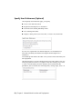
See the following table for hardware and software requirements.
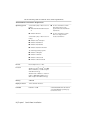
32-bit Hardware and Software Requirements
Operating systems
Service Pack 2 (SP2) or later for the following:
■
Microsoft® Windows® XP Professional
■
Windows XP Home
Service Pack 1 (SP1) or later for the following:
■
Windows Vista® Enterprise
■
Windows Vista Business
■
Windows Vista Ultimate
■
Windows Vista Home Premium
■
For more information on Windows Vista versions see http://www.microsoft.com/windowsvista/versions/
■
For more information on Windows 7 see http://www.microsoft.com/windows7
The following operating systems:
■
Windows 7 Enterprise
■
Windows 7 Ultimate
■
Windows 7 Professional
■
Windows 7 Home Premium
Browser
Internet Explorer® 7.0 or later
Processor
Windows XP - Intel® Pentium® 4 or AMD
Athlon™ Dual Core, 1.6 GHz or higher
with SSE2 technology
Windows Vista or Windows 7 - Intel Pentium 4 or AMD Athlon Dual Core, 3.0
GHz or higher with SSE2 technology
Memory
2 GB RAM
Display resolution
1024 x 768 with True Color
Hard disk
Installation 1.8 GB
2 | Chapter 1 Stand-Alone Installation
A 32-bit AutoCAD cannot be installed
on a 64-bit Windows operating system and vice-versa.
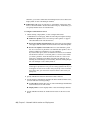
32-bit Hardware and Software Requirements
Pointing device
MS-Mouse compliant
Additional Requirements for3D Modeling
■
Intel Pentium 4 or AMD Athlon
processor, 3.0 GHz or higher; or Intel or AMD Dual Core processor, 2.0
GHz or higher
■
2 GB RAM or more
■
2 GB free hard disk space available
not including installation
■
1280 x 1024 32-bit color video display adapter (True Color) 128 MB
or greater, Pixel Shader 3.0 or
greater, Direct3D® capable workstation class graphics card
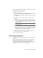
64-bit Hardware and Software Requirements
Operating systems
Service Pack 2 (SP2) or later for the following:
■
■
For more information on Windows Vista versions see http://www.microsoft.com/windowsvista/versions/
■
For more information on Windows 7 see http://www.microsoft.com/windows7
Microsoft® Windows® XP Professional
Service Pack 1 (SP1) or later for the following:
■
Windows Vista® Enterprise
■
Windows Vista Business
■
Windows Vista Ultimate
The following operating systems:
Browser
■
Windows 7 Enterprise
■
Windows 7 Business
■
Windows 7 Ultimate
■
Windows 7 Professional
■
Windows 7 Home Premium
Internet Explorer 7.0 or later
System Requirements | 3
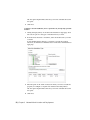
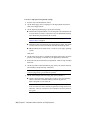
64-bit Hardware and Software Requirements
CPU type
AMD Athlon 64 with SSE2 technology
AMD Opteron™ with SSE2 technology
Intel Xeon® with Intel EM64T support and
SSE2 technology
Intel Pentium 4 with Intel EM64T support
and SSE2 technology
Memory
2 GB RAM
Display resolution
1024 x 768 with True Color
Hard disk
Installation 2 GB
Pointing device
MS-Mouse compliant
3D Modeling Additional Requirements
■
Intel Pentium 4 or AMD Athlon processor, 3.0 GHz or higher; or Intel or
AMD Dual Core processor, 2.0 GHz or
higher
■
2 GB RAM or more
■
2 GB free hard disk space available not
including installation
■
1280 x 1024 32-bit color video display
adapter (True Color) 128 MB or
greater, Pixel Shader 3.0 or greater,
Direct3D capable workstation class
graphics card
A 64-bit AutoCAD cannot be installed on a 32-bit Windows operating system and vice-versa.
NOTE Adobe Flash Player is not installed by default. If a version of Flash is not
currently installed on your system, a message is displayed requesting that you
install it. Flash Player can be installed from the product media or Adobe’s website
- www.adobe.com.
4 | Chapter 1 Stand-Alone Installation
Administrative Permission Requirements
To install AutoCAD, you must have administrator permissions. You do not
need to have domain administrative permissions. See your system administrator
for information about administrative permissions.
You do not need administrator permissions to run AutoCAD. You can run the
program as a limited user.
Locating Your Serial Number and Product Key
When you install AutoCAD, you are prompted for your serial number and
product key in the Product and User Information page, or the option of
installing the product in trial mode. You may enter your product information
at any time during your trial mode period if you opt to install the product in
that mode.
The serial number and product key are located on the outside of the product
packaging, or in the Autodesk® Upgrade and Licensing Information email.
Make sure to have these available before you install the program so that you
don't have to stop in the middle of the installation.
The serial number must contain a three-digit prefix followed by an eight-digit
number. The product key consists of five characters.
The information you enter is permanently retained with the product. Because
you can't change this information later without uninstalling, take care when
entering the information. To review this product information later, on the
Administrative Permission Requirements | 5
InfoCenter toolbar, click the drop-down arrow next to the Help button (the
question mark). Then click About - Product Information.
NOTE If you have lost your serial number or product key, contact the Autodesk
Business Center (ABC) at 800-538-6401 for assistance.
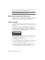
Minimize the Chances of Installation Failure
The AutoCAD installation process may stop if some applications such as
®
®
Microsoft Outlook or virus-checking programs are running. Close all running
applications to avoid possible installation problems and data loss.
Choose a Language
You can specify both the language in which the installation or deployment
instructions are displayed, and the language of the products being installed
or deployed.
As you begin an installation or create a deployment, the installer detects your
operating system’s language. If the detected language is supported, your
installation or deployment instructions are displayed in that language. You
can change the language for the instructions from the Language drop-down
list on the initial page of the installation wizard.
To change the language of the products being installed or deployed, select
another language on the Select the Products to Install or Select the Products
to Include in the Deployment pages.
The following rules apply to language selection:
■
Only one language can be chosen for each installation session. For example,
you cannot select English for one product, and then select German for
another product during the same installation.
■
Only one language can be chosen during deployment creation. One
administrative image can contain deployments for different languages,
but each deployment must be targeted for one language.
6 | Chapter 1 Stand-Alone Installation
■
If you are editing an existing deployment, or creating a new deployment
using an existing deployment as a template, the Language drop-down list
is unavailable. The existing deployment’s language is used.
■
If a language is not supported, a default language is used.
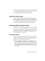
Migrating Custom Settings
You can migrate your custom settings and files from previous releases of
AutoCAD (AutoCAD 2000 through AutoCAD 2011). It is recommended that you
migrate custom settings from a previous release right away. This prevents you
from overwriting files or having to keep track of any custom settings you may
make in the new release. Migrating settings overwrites any new settings.
For more details regarding migration, see Migrating and Customizing.
Installing and Running the Product
To use the product, you must install the product, register and activate it, and
then launch it. You must have administrative permissions to install AutoCAD.
This section provides instructions for installing and activating AutoCAD for
an individual user on a stand-alone computer. For information about installing
network-licensed or multi-seat stand-alone versions of the program, see
Network Administration and Deployment.
Installing AutoCAD
The AutoCAD Installation wizard contains all installation-related material in
one place. From the installation wizard, you can access user documentation,
change the installer language, select a language for your product, install
supplemental tools, and add online support services.
■
Review the installation documentation. It is recommended that you take
the time to familiarize yourself with the complete installation process
before you install AutoCAD. You can access information on installation
from the installation wizard by selecting the Read this Documentation option,
the Documentation and information links, or through the Help system.
For late-breaking information, it is also recommended that you review the
product Readme.
Migrating Custom Settings | 7
Install AutoCAD Using Default Settings on a Stand-Alone
Computer
Using the default installation settings is the fastest way to install AutoCAD
on a single, stand-alone system. A default installation does the following:
■
Performs a Typical installation, which installs the most common
application features.
■
Installs the Express Tools library, which provides additional productivity
tools.
■
Installs AutoCAD to the default installation path of C:\Program
Files\Autodesk\<product name>.
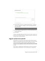
To install the product using default settings
1 Start the AutoCAD Installation wizard.
2 On the initial page, select a language for the installation instructions.
Click Install Products.
3 On the Select the Products to Install page, select your product(s) and the
product language. Click Next.
4 Review the Autodesk software license agreement. Click I Accept, and then
click Next.
5 On the User and Product Information page, enter your user information,
serial number, and product key. Click Next.
8 | Chapter 1 Stand-Alone Installation
WARNING After you click Next, you cannot change the information entered
on this page unless you uninstall the product.
6 On the Begin Installation page, click Install. In the configuration warning
message, click Yes.
7 On the Installation Complete page, you can view the installation log and
the AutoCAD Readme.
8 Click Finish.
You have successfully installed AutoCAD. You are now ready to register your
product and start using the program. To register the product, start AutoCAD
and follow the on-screen instructions.
Install AutoCAD Using Custom Settings on a Stand-Alone
Computer
With this method, you can customize your installation.
Installing AutoCAD | 9
To install the product using custom settings
1 Start the AutoCAD Installation wizard.
2 On the initial page, select a language for the installation instructions.
Click Install Products.
3 On the Select the Products to Install page, select your product(s) and the
product language. Click Next.
4 Review the Autodesk software license agreement. Click I Accept, and then
click Next.
5 On the User and Product Information page, enter your user information,
serial number, and product key. Click Next.
WARNING After you click Next, you cannot change the information entered
on this page unless you uninstall the product.
6 On the Begin Installation page, click Configure.
7 On the Select the License Type page, select the license type (Stand-alone
or Network). Click Next.
8 On the Select the Installation Type page, specify the following:
■
Installation Type. Select Typical to install the most common application
features. Select Custom to install only the application features that
you select from the Select Features to Install list.
■
Create the Desktop Shortcut for AutoCAD - <Language>. Clear the check
box if you do not want to create a shortcut to the program.
■
Product Install Path - Specify the drive and location where you want to
install AutoCAD.
Click Next.
9 On the Include Service Pack page, specify whether to include available
service packs. The installer automatically checks autodesk.com for available
updates.
10 | Chapter 1 Stand-Alone Installation
10 Click another product tab to configure another product, or click Next
and then Configuration Complete to return to the Begin Installation
page. Click Install.
NOTE To retain a copy of your configuration settings, click Copy to Clipboard.
11 On the Installation Complete page, you can view the installation log or
the AutoCAD Readme.
12 Click Finish.
You have successfully installed AutoCAD. You are now ready to register your
product and start using the program. To register the product, start AutoCAD
and follow the on-screen instructions.
Register and Activate AutoCAD
The first time you start AutoCAD, the Product License Activation wizard is
displayed. You can either activate AutoCAD at that time, or Try AutoCAD and
activate it later. Until you register and enter a valid activation code for
AutoCAD, you are operating the program in trial mode and the Product License
Activation wizard is displayed for 30 days from the first time that you run the
program.
If after 30 days of running AutoCAD in trial mode you have not registered
and provided a valid activation code, your only option is to register and
Register and Activate AutoCAD | 11
activate AutoCAD. You will not be able to run in trial mode after the 30 days
expires. Once you register and activate AutoCAD, the Product License
Activation wizard is no longer displayed.
The fastest and most reliable way to register and activate your product is by
using the Internet. Simply enter your registration information and send it to
Autodesk over the Internet. Once you submit your information, registration
and activation occur quickly.
To register and activate AutoCAD
1 Click the Start menu ➤ Programs or All Programs ➤ Autodesk ➤
<AutoCAD> ➤ <AutoCAD>.
2 In the AutoCAD Product License Activation wizard, select Activate, and
then click Next.
This starts the activation process.
3 Click Register and Activate (Get an Activation Code).
4 Click Next and follow the on-screen instructions.
If you do not have Internet access, or if you want to use another method
of registration, you can register and activate AutoCAD in one of the
following ways:
Email Create an email message with your registration information and
send it to Autodesk.
Fax or Post/Mail Enter your registration information, and fax or mail
the information to Autodesk.
Launch AutoCAD
Assuming that you followed all of the previous steps outlined in this
installation section, you can launch AutoCAD and start taking advantage of
its new and updated features. For more detailed information about the new
features, learning videos, online Help, or AutoCAD services and support, see
the Welcome screen after you launch the product.
You can start AutoCAD in the following ways:
■
Desktop shortcut icon. When you install AutoCAD, an AutoCAD shortcut
icon is placed on your desktop unless you cleared that option during
installation. Double-click the AutoCAD shortcut icon to start the program.
12 | Chapter 1 Stand-Alone Installation
■
Start menu. On the Start menu, click Programs or All Programs ➤ Autodesk
➤ <AutoCAD> ➤ <AutoCAD>.
■
Location where the AutoCAD is installed. If you have administrative
permissions, you can run AutoCAD in the location where you installed it.
If you are a limited-rights user, you must run AutoCAD from the Start
menu or from the desktop shortcut icon. If you want to create a custom
shortcut, make sure that the Start In directory for the shortcut points to a
directory where you have write permissions.
Add or Remove Features
You can add or remove AutoCAD features at any time. For example, you may
have chosen a Custom installation option when you first installed AutoCAD,
but now you want to add features that you did not install originally. Or you
may no longer need to use all of the features that were installed originally.
You can add or remove features by using the Add or Remove Programs dialog
box.
To add or remove features
1 Click the Start menu ➤ Programs or All Programs ➤ Autodesk ➤
<AutoCAD> ➤ <AutoCAD>.
2 In the Add or Remove Programs (XP) or Uninstall or Change a Program
(Vista) dialog box, click AutoCAD, and then click Change/Remove.
The AutoCAD Installation wizard re-opens in Maintenance Mode.
3 Click Add or Remove Features.
4 On the Add/Remove Features page, select a feature to install or uninstall.
The icons to the left of the selections give you an indication of the action
that will be taken.
Indicates a feature that was marked for installation will be in a typical
installation.
Indicates a feature that is not currently scheduled for installation.
Indicates a feature that was not originally marked for installation,
but was added to the installed feature list.
Indicates an installed feature that is chosen for removal.
Add or Remove Features | 13
NOTE If you need to revert to AutoCAD features that you selected in your
original installation, click Cancel.
Click Next.
5 On the Update AutoCAD Installation page, click Next.
6 On the Update Complete page, you are informed when the updates have
been performed. Click Finish.
Reinstall or Repair AutoCAD
If you accidentally delete or alter files that are required by AutoCAD, AutoCAD
might not perform correctly, and you might receive error messages when you
try to execute a command or find a file. You can attempt to fix this problem
by reinstalling or repairing AutoCAD. The reinstallation or repair uses the
features that were part of the installation type you chose when you initially
installed the program.
To reinstall or repair AutoCAD
1 Click the Start menu ➤ Programs or All Programs ➤ Autodesk ➤
<AutoCAD> ➤ <AutoCAD>.
2 Then, do one of the following:
■
(Windows XP) In the Add or Remove Programs window, select
AutoCAD, then click Change/Remove.
■
(Windows Vista) In the Uninstall or Change a Program, select
AutoCAD, then click Uninstall/Change.
The AutoCAD Installation wizard re-opens in Maintenance mode.
3 Select Repair or Reinstall. On the Select Repair or Reinstall page, select
one of the following options, and then click Next to start the process.
■
Repair My <AutoCAD> Installation. This option replaces all registry
entries that AutoCAD initially installed and restores AutoCAD to its
default state. If you are missing AutoCAD files, use this option.
■
Reinstall My <AutoCAD> Installation. This option repairs the registry
and reinstalls all files from the original installation. Use this option
if the Repair My <AutoCAD> Installation option does not solve the
problem.
14 | Chapter 1 Stand-Alone Installation
4 On the Repair Complete page, click Finish.
Uninstall AutoCAD
When you uninstall AutoCAD, all components are removed. This means that
even if you've previously added or removed components, or if you've reinstalled
or repaired AutoCAD, the uninstall removes all AutoCAD installation files
from your system.
To uninstall AutoCAD
1 Click the Start menu ➤ Programs or All Programs ➤ Autodesk ➤
<AutoCAD> ➤ <AutoCAD>.
2 Then, do one of the following:
■
(Windows XP) In the Add or Remove Programs window, select
AutoCAD, then click Change/Remove.
■
(Windows Vista) In the Uninstall or Change a Program window, select
AutoCAD, then click Uninstall/Change.
The AutoCAD Installation wizard re-opens in Maintenance mode.
3 Click Uninstall.
4 On the Uninstall <AutoCAD> page, click Next to remove AutoCAD from
the system.
5 When informed that the product has been successfully uninstalled, click
Finish.
NOTE Even though AutoCAD is removed from your system, the software license
remains. If you reinstall AutoCAD at some future time, you will not have to register
and re-activate the program.
Installing Multiple or Bundled Products
Some Autodesk packages are comprised of multiple products or are part of
multi-product bundles.
In the installation wizard, for packages containing multiple products, you can
choose which products and languages you want to install. During the install
process, you are informed whether a copy of the software is already installed.
Uninstall AutoCAD | 15
You are also warned if your system does not meet the minimum system
requirements for the product. Each product name is displayed on its own
tabbed panel; you can configure them individually.
If you purchased a package that is a multi-product bundle, such as an
educational or institutional package, you may have a package that includes
several Autodesk products. For these bundled packages, an Installer disc
contains information for all the products in the package. The Installer disc
helps you install all of the products.
Installing Design Review
Autodesk Design Review 2011 is not installed by default when you install
AutoCAD. It is recommended that Design Review be installed if you need to
view DWF or DWFx files.
NOTE If you are installing Autodesk Design Review 2011, it is recommended that
you first manually uninstall older versions of Autodesk Design Review and any
other DWF viewers using Add or Remove Programs (XP), or Programs and Features
(Vista). After uninstalling, check the program folders to make sure they are empty
before installing Design Review 2011.
Autodesk Design Review is a free program used for creating and reviewing
DWF or DWFx files. An open, published, and secure file format developed by
Autodesk, DWF enables you to combine and publish rich 2D- and 3D-design
data, and share it with others.
The following commands create DWF or DWFx files.
■
PUBLISH
■
PLOT
■
3DDWF
■
PUBLISH TO WEB
■
EXPORT
■
AUTOPUBLISH
■
SSM
NOTE If you use Windows Vista, you can use the Microsoft XPS Viewer to view
and print DWFx files without installing Design Review.
16 | Chapter 1 Stand-Alone Installation
Installing Autodesk Material Libraries
The Autodesk material libraries are shared libraries installed with Autodesk
products such as Inventor, AutoCAD, Revit and 3ds Max.
NOTE If you uninstall or remove a library, the library is no longer available for any
product. Uninstalling also means you will be unable to view or display drawings
that have materials currently in them.
The Autodesk material libraries include the following:
■
Autodesk Material Library 2011 (CM): Contains the new material library
(approximately 256 x 256). This library is installed by default, and required
for AutoCAD to have full visual style and color style functionality. It is
recommended that you do not uninstall this library unless you are also
uninstalling all Autodesk products that require this library.
■
Autodesk Material Library 2011 Base Image Library (ILL): Contains low
resolution images (approximately 512 x 512) for use with Autodesk
materials. This is also installed by default. It is recommended that you do
not uninstall this library unless you are also uninstalling all Autodesk
products that require this library.
■
Autodesk Material Library 2011 Medium Image Library (ILM): Contains
medium resolution images (approximately 1024 x 1024) for rendering
materials in medium detail. This library is used for close-ups, and for
rendering objects at a larger scale. This library is an installation option
available on the Select Products to Install page in the installation wizard.
If you uninstall the Base Image Library, and do not have the Medium Image
Library installed, the lowest resolution library (Material Library) is used.
Reinstall Autodesk Material Libraries
If you uninstall or delete material libraries, you can reinstall them to regain
visual style and color style functionality. You must reinstall the Material
Library (CM) before the Base (ILL) and Medium (ILM) Libraries. The Windows
installer log will be inaccessible if the libraries are not reinstalled in the
recommended order.
To reinstall Autodesk Material Library 2011
■
From the product media, browse to and run:
\support\ADSKMaterials\CM\ProteinMaterials.msi
Installing Autodesk Material Libraries | 17
To reinstall Autodesk Material Library 2011 Base Image Library
■
From the product media, browse to and run:
\support\ADSKMaterials\ILL\BaseImageLibrary.msi
To reinstall the Autodesk Material Library 2011 Medium Image Library
1 Insert the media. Select Install Products from the installation wizard.
2 On the Select the Products to Install page, select Autodesk Material Library
2011 Medium Image Library, and then click Next.
3 Review the Autodesk software license agreement. Click I Accept, and then
click Next.
4 On the User and Product Information page, enter your user information,
serial number, and product key. Click Next.
5 On the Begin Installation page, click Install.
6 On the Installation Complete page, click Finish.
18 | Chapter 1 Stand-Alone Installation
Migrating and Customizing
2
If you have a previous version of AutoCAD installed on your system, you can install a newer
version of AutoCAD and keep other versions of the program on the same system. This is called
a side-by-side installation. If you have purchased an upgrade version of AutoCAD, you are
required to uninstall the previous version within 120 days of installing your newer product.
See your license agreement for more information.
In this section, you learn about migrating from previous releases and using customized files
from previous releases.
Migrate Custom Settings and Files from Previous
Releases
You can migrate your custom settings and files from previous releases of
AutoCAD to your new release. It is recommended that you migrate from a
previous release right away. This prevents you from overwriting files or having
to keep track of any custom settings you may make in the new release. Migrating
settings overwrites any new settings.
You can use the following tools to migrate settings and files:
■
Migrate Custom Settings dialog box. Migrates user profiles, CUI and CUIx
files, tool palette files, AutoCAD and user-defined linetype files, AutoCAD
and user-defined hatch patterns, and the acad.pgp file (a file that stores
command definitions and aliases). The Migrate Custom Settings dialog box
is displayed when you start the product for the first time. You can also
migrate settings later from the Start menu (Windows).
NOTE The release of the product from which you are migrating determines
which custom settings and files can be migrated to the new release.
19
■
Customize User Interface dialog box. Converts legacy menu (MNU and
MNS) and CUI files to the CUIx format while leaving the original file
unchanged. Migrating user interface elements, transferring data between
customized files, and customizing user interface elements are simplified
in this dialog box. For more information about the CUIx file format and
how to migrate menu and CUI files, see User Interface Customization in
the Customization Guide.
■
Migration tools. Aid migration of settings or files that cannot be
®
automatically migrated (such as AutoLISP files and the accompanying
MNL files) or that require you to make a decision about which files to
migrate (such as which files in a set of drawing files). Download these
migration tools by visiting www.autodesk.com and then performing a search
on Migration Tools.
NOTE For information about customizing files and settings, see the Customization
Guide, accessible from the Documentation link on the AutoCAD Installation wizard
and in the Help system.
Migrate Custom Settings
If you install AutoCAD on a computer where a previous release of the AutoCAD
product is installed, you can migrate some custom settings from a previous
release to your newer AutoCAD product.
Migrate the user profile. This file contains drawing environment settings such
as screen color, cursor size, command line window font, and the dictionary
to use for checking spelling. The user profile file also includes the folders in
which AutoCAD searches for support, driver, customization, and other files.
If you customized files in a location other than the default AutoCAD location,
the path to the location is migrated. The files themselves do not get migrated.
Migrate linetypes, hatch patterns, and command aliases that you created.
The data from these files is added to a user-defined section of the AutoCAD
files, to make it easy for you to find this information and migrate this data to
future releases. You cannot use the Migrate Custom Settings dialog box to
migrate shell commands or comments that you made to your acad.pgp file.
NOTE If you have made changes to partial plotter configuration (PC3) files that
are located in a custom folder, those files are migrated to the AutoCAD PC3 folder,
which is located under your custom PC3 folder. PC3 files are migrated to a separate
folder to maintain backward compatibility with previous AutoCAD releases.
20 | Chapter 2 Migrating and Customizing
The following table lists the files that are migrated with the Migrate Custom
Settings dialog box, a description of each file, and file details to help you
decide if you want to migrate a file.
Files Migrated with the Migrate Custom Settings Dialog Box
File Name File Description
Details
*.atc
Defines a tool palette and its
tools.
User-created files and any new or
changed tools on a standard tool
palette are migrated.
*.arg
Used to back up user profile information from the system registry. The ARG file is not migrated. Registry settings are migrated.
Changes you make to your user profile are stored in the system registry
and are migrated.
*.lin
Stores your user-defined linetypes.
User-defined linetype files are migrated.
acad.lin
Contains standard linetype definitions (an AutoCAD library file).
The file itself is not migrated; however, any linetypes that you created
in this file are migrated to the AutoCAD acad.lin file, in the User Defined
Linetypes section of the file.
acadiso.lin
Contains metric linetype definitions (an AutoCAD library file).
The file itself is not migrated; however, any linetypes that you created
in this file are migrated to the AutoCAD acadiso.lin file, in the User
Defined Linetypes section of the file.
*.pat
Stores user-defined hatch patterns.
User-defined hatch pattern files are
migrated.
acad.pat
Contains standard hatch pattern
definitions (an AutoCAD library
file).
The file itself is not migrated; however, any hatch patterns that you
created in this file are copied to the
AutoCAD acad.pat file, in the User
Defined Hatch Patterns section of the
file.
Migrate Custom Settings | 21
Files Migrated with the Migrate Custom Settings Dialog Box
File Name File Description
Details
acadiso.pat
Contains metric hatch pattern
definitions (an AutoCAD library
file).
The file itself is not migrated; however, any metric hatch patterns that
you created in this file are copied to
the AutoCAD acadiso.pat file, in the
User Defined Hatch Patterns section
of the file.
acad.pgp
Stores shell commands and command alias definitions (a program
parameters file in ASCII text
form).
The file itself is not migrated; however, any command aliases you created in this file are copied to the
AutoCAD acad.pgpfile.
*.mnu
Contains menu customization
from a release prior to AutoCAD
2006.
The file itself is not migrated; a copy
of the file is created and converted
into a CUIx file with the same name.
The new CUIx file is stored in the
same folder as the main CUIx file. An
MNU file is converted when an MNS
file with the same name is not found.
*.mns
Contains menu customization
from a release prior to AutoCAD
2006.
The file itself is not migrated; a copy
of the file is created and converted
into a CUIx file with the same name.
The new CUIx file is stored in the
same folder as the main CUIx file. An
MNS file is converted whether or not
an MNU file with the same name is
present.
*.cui
Contains customizations from
AutoCAD 2006 through .
The file itself is not migrated; a copy
of the file is created and converted
into a CUIx file with the same name.
The new CUIx file is stored in the
same folder as the main CUIx file.
Enterprise CUI files are not automatically migrated. You must do so
manually.
*.cuix
Contains customizations from
and later.
If the CUIx file is supplied by
Autodesk, the custom changes made
22 | Chapter 2 Migrating and Customizing
Files Migrated with the Migrate Custom Settings Dialog Box
File Name File Description
Details
to the file are migrated to the newer
version of the CUIx file.
If the CUIx file is not supplied by
Autodesk, the file is migrated and
copied to the location of the main
CUIx file, unless the CUIx file is in a
network location. In that case, the
file is migrated but is not copied to
the location of the main CUIx file.
Enterprise CUIx files are not automatically migrated. You must do so
manually.
Before MNU, MNS, CUI, and CUIx files are migrated, a backup copy of each
file is saved in the following directory:
■
(Windows XP) <drive>:\Documents and Settings\<user profile>\Application
Data\Autodesk\<product version>\<release number>\<language>\Previous Version
Custom Files
■
(Windows Vista) <drive>:\Users\<user profile>\Application
Data\Autodesk\<product version>\<release number>\<language>\Previous Version
Custom Files
NOTE Other custom settings and files can be migrated using Autodesk migration
tools. For more information about migration tools, see Use Migration Tools on
page 25.
To migrate custom settings when you start the AutoCAD
1 Start AutoCAD.
2 In the Migrate Custom Settings dialog box, Migrate Settings From
drop-down list, select the AutoCAD release from which you want to
migrate your custom settings.
3 In the Settings and Files to Migrate box, select the custom files that you
want to migrate.
4 Click OK.
Migrate Custom Settings | 23
5 In the Migrate Custom Settings message, click OK to view the log file, or
click No if you do not want to view the log file now.
NOTE You can view the log file at another time. For information about
accessing the log file at another time, see View the Migration Log File on
page 24.
Each time the Migrate Custom Settings dialog box is used, AutoCAD resets
the program’s default CUIx file from the UserDataCache folder and then
migrates any customization done in a previous release forward.
To migrate custom settings from the Start menu (Windows)
1 Do one of the following:
■
(Windows XP) Click Start menu ➤ Programs ➤ Autodesk ➤
<AutoCAD> ➤ Migrate Custom Settings ➤ Migrate From a Previous
Release.
■
(Windows Vista) Click Start menu ➤ All Programs ➤ Autodesk ➤
<AutoCAD> ➤ Migrate Custom Settings ➤ Migrate From a Previous
Release.
2 In the Migrate Custom Settings dialog box, Migrate Settings From
drop-down list, select the AutoCAD release from which you want to
migrate your custom settings.
3 In the Settings and Files to Migrate box, select the custom files that you
want to migrate.
4 Click OK.
5 In the Migrate Custom Settings message, click OK to view the log file, or
click No if you do not want to view the log file.
NOTE To be accessible, pull-down menus that are migrated from a MNU/MNS
file to a CUIx file need to be added to a workspace.
View the Migration Log File
The migration log file (migration.xml) provides specific information about any
settings or files that were not successfully migrated to AutoCAD. The log file
shows all the files that were successfully copied from a previous version to the
24 | Chapter 2 Migrating and Customizing
newer AutoCAD. It also provides information about files that were not
successfully migrated. Use the log for troubleshooting if there are unwanted
or unexpected results in your AutoCAD profiles.
After you use the Migrate Custom Settings dialog box to migrate custom
settings and files, a message is displayed from which you open the migration
log file. You can view the migration log file at that time. You can also navigate
to the file if you want to view the log details another time.
To locate and view the migration log file
1 In Windows Explorer, navigate to the following location:
■
(Windows XP) <drive>:\Documents and Settings\<user
profile>\Application Data\Autodesk\<product version>\<release
number>\<language>\Migration
■
(Windows Vista) <drive>:\Users\<user profile>\Application
Data\Autodesk\<product version>\<release
number>\<language>\Migration
2 Double-click migration.xml to open the file, and view the details of your
migration.
Restore Profiles After Migrating Files from an Earlier Release
After you migrate your profiles from an earlier AutoCAD release, you may
want to restore the newer AutoCAD default profile settings.
To restore AutoCAD default profiles
1 On the Application menu, click Options.
2 In the Options dialog box, Profiles tab, click the profile you want to
restore and click Reset.
3 Click Yes.
The profile is reset to the newer default profile.
Use Migration Tools
Migration tools take the guesswork out of updating your custom files from
previous releases. The tools help you to share drawings when you upgrade to
Use Migration Tools | 25
a new release of an AutoCAD product. You can download the migration tools
in several languages from the Autodesk website.
NOTE Because these are public tools, product support for them is limited to the
Autodesk discussion groups.
The migration tools are as follows:
■
DWG TrueView 2011. You can view, plot, and convert any AutoCAD
product or an AutoCAD product-based drawing file for compatibility with
the current AutoCAD drawing file formats.
■
ScriptPro. Using ScriptPro, you can apply a set of commands to multiple
drawings by specifying a script file and the list of drawings to which you
want to apply the script.
■
AutoLISP Compatibility Analyzer. Details AutoCAD compatibility issues
found in AutoLISP files and the accompanying menu (MNL) files. When
a compatibility issue is found, the tool provides an explanation of the issue
and suggestions on how to correct it.
Customize AutoCAD with Initial Setup
With Initial Setup you can perform some basic customization of AutoCAD.
You respond to a series of questions that are used to gather information about
specific features and settings in AutoCAD. You specify which industry best
describes your work, add task-based tools to your default workspace, and
specify the drawing template you want to use when creating a new drawing.
Select an Industry
When Initial Setup is displayed, you are prompted to select an industry. Select
one of the listed industries that is closest to the type of work that best describes
the drawings you create. The following features and settings in AutoCAD and
Initial Setup are affected by the industry you select:
■
Content Search. Used as part of a generated query to find content from
Autodesk Seek.
■
Partner product search. Used as part of a generated query that is sent to
the Autodesk Partner Products website to find relevant third-party utilities
that might be beneficial to your work.
26 | Chapter 2 Migrating and Customizing
■
Initial Setup. Used to determine which drawing template file might be
appropriate to your industry for new drawings when compared to the
supplied default templates that come with AutoCAD.
Add Task-based Tools
With Initial Setup, you can add task-based tools to your default workspace
(for example tools to review red-line markups created from Autodesk Design
Review or tools used to create photorealistic renderings).
The following task-based tools can be added to your default workspace from
Initial Setup:
■
3D modeling
■
Photorealistic rendering
■
Review and markup
■
Sheet sets
Customize AutoCAD with Initial Setup | 27
You can use the Customize User Interface (CUI) Editor to further control which
task-based tools are displayed in a workspace. For more information about
workspaces, see Customize Workspaces in the Customization Guide.
Specify a Default Drawing Template
With drawing templates you can reuse a set of settings and styles when you
create a new drawing. In Initial Setup you can specify the default drawing
template to use when you create a new drawing. Initial Setup has the following
drawing template options:
■
Default drawing template. Use the imperial or metric drawing template
that is installed by default.
■
Existing drawing template. Specify an existing drawing template that is
available on a local or network drive.
If you migrated your custom settings and files from a previous release, the
migrated default drawing template file is listed. For information about
migrating custom settings and files from a previous release, see Migrate
Custom Settings on page 20.
28 | Chapter 2 Migrating and Customizing
■
Industry focused drawing template. Use the drawing template that is
associated with the industry you selected in Initial Setup, and either the
imperial or metric measurement type.
Drawing templates are often project- or company-specific to ensure consistent
styles and settings from one drawing to the next. It is recommended that you
use a drawing template that follows your company’s CAD standards.
For information about creating a custom drawing template, see Use a Template
File to Start a Drawing in the User’s Guide.
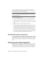
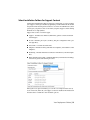
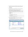
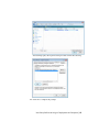
To customize AutoCAD with Initial Setup
1 Click the Application menu button ➤ Options.
2 In the Options dialog box, User Preferences tab, click Initial Setup.
3 In Initial Setup, Industry page, specify an industry that best describes
your work. Click Next.
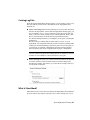
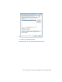
4 On the Optimize Your Workspace page, select the task-based tools you
want to display in your default workspace. Click Next.
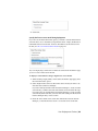
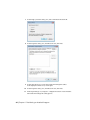
5 On the Specify a Drawing Template File page, select the drawing template
file that you want to use when creating new drawings. Click Finish.
6 In the Options dialog box, click OK.
Customize AutoCAD with Initial Setup | 29
Export and Import Custom Settings from the Same
Release
You can export your custom settings between systems running the same release
of an AutoCAD product, or export the custom settings and later re-import
them on the same computer if you need to reinstall AutoCAD. When exporting
custom settings, a migration package is created that contains an XML file.
This file contains custom settings, a listing of the custom files from local
locations used with AutoCAD, and optionally, custom files in network
locations.
The migration package is a ZIP file archive, so it has the file extension ZIP.
During the import process, you select the ZIP file archive that contains the
exported custom settings you want to merge onto your computer.
The following table lists the file types that are most commonly included in
the migration package that is created from the Export Custom Settings dialog
box.
Most Common File Types Included in the Migration Package
File Name File Description
*.atc
Tools defined on a tool palette and the tool palette catalog. The file is
not migrated from release to release, but is from computer to computer
with the migration package.
*.aws
Order of the tools as they appear on a tool palette and other local settings.
The file is not migrated from release to release, but is from computer to
computer with the migration package.
*.bmp
Image used for a command in a customization file.
*.ctb
Settings used to control the appearance of objects when plotting; the
settings are arranged by the colors of the AutoCAD Color Index (ACI)
system.
*.cuix
Information for commands and user interface elements.
*.cus
Custom dictionary entries.
*.fmp
Information about font mappings for True Type Fonts used in the In-place
Text Editor.
30 | Chapter 2 Migrating and Customizing
Most Common File Types Included in the Migration Package
File Name File Description
*.ini
Configuration settings for some features.
*.lin
Linetype definitions.
*.mln
Multiline style definitions.
*.mnl
AutoLISP commands and procedures that a customization file is dependent
on; must have the same name as a customization file in order to be loaded
by the product.
*.pat
Hatch pattern definitions.
*.pc3
Configuration information for a plotter or printer.
*.pgp
Shell commands and command alias definitions.
*.pmp
Calibration and paper size settings that are used with a PC3 file.
*.psf
Information about font substitution when exporting to a Postscript file.
*.shx
Information about text characters or shapes used with linetype definitions.
*.stb
Settings used to control the appearance of objects when plotting; the
settings are grouped into names that can be assigned to a layer or object.
*.xml
Information about the user profiles in the product and the original locations of the files in the export package.
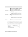
The following table lists the file types that are not included in the migration
package that is created from the Export Custom Settings dialog box.
Some of the File Types Not Included in the Migration Package
File Name File Description
*.actm
Action macro file.
*.arx
ObjectARX application file.
*.dcl
Definitions for custom dialog boxes used with AutoLISP, ADS, or ObjectARX applications.
Export and Import Custom Settings from the Same Release | 31
Some of the File Types Not Included in the Migration Package
File Name File Description
*.dvb
Visual Basic for Applications project file.
*.fas
Fast-load AutoLISP format file.
*.fdc
Definitions for fields; should not be modified.
*.lli
Landscape library; this file type is no longer supported due to the removal
of the LANDSCAPE command.
*.lsp
AutoLISP source file that contains definitions for custom commands and
functions.
*.mli
Render material library; this file type is no longer supported due to changes
to the MATERIALS command.
*.mnr
Resource images for a customization file; must have the same name as a
customization file in order to be loaded by the product. The file is not
included because it is auto-generated by the product when it is not
present.
*.udl
Data connection settings used with dbConnect.
*.unt
Unit definitions used for converting a value from one unit type to another.
*.vlx
Visual LISP file that might contain multiple AutoLISP and DCL files compiled into a single file.
NOTE For information about customizing files and settings, see the Customization
Guide, accessible from the Documentation link on the AutoCAD Installation wizard
and in the Help system.
Export Custom Settings
When exporting custom settings, the custom files stored locally and all user
profiles are exported to a migration package. You have the option to include
custom files that are stored in network locations. During the creation of the
migration package, you do not have any control over which types of files are
included in the migration package.
32 | Chapter 2 Migrating and Customizing
The Export Custom Settings dialog box is used to create the migration package
so it can be imported to another computer or the same computer running the
same release of the product.
NOTE You must launch AutoCAD at least once before you can export custom
settings to a migration package.
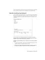
To export custom settings
1 Do one of the following:
■
(Windows XP) Click Start menu ➤ Programs ➤ Autodesk ➤
<AutoCAD> ➤ Migrate Custom Settings ➤ Export <AutoCAD> Settings.
■
(Windows Vista) Click Start menu ➤ All Programs ➤ Autodesk ➤
<AutoCAD> ➤ Migrate Custom Settings ➤ Export <AutoCAD> Settings.
2 In the Export Custom Settings dialog box, select the Include Custom Files
in Networked Locations option if you have files in network locations that
you want included in the migration package that is created.
3 Click Export.
4 In the Export Custom Settings file navigation dialog box, enter a name
and specify a location for the migration. Click Open.
A new ZIP file is created.
5 In the confirmation message box, click OK.
Import Custom Settings
By importing a migration package, you can configure AutoCAD in the same
way as other computers that are running the same release of the product.
Upon the successful import of the migration package, a message box is
displayed giving you the option of viewing the migration log that is created.
If any errors are encountered during the import process, they are logged in
the migration log.
If files from a network location were added during the creation of a migration
package, the files are copied to a different location only when the original
network locations are not available when importing a migration package. If
the files from a network location are found in the same location on the
network, the files are not copied to the network location and are ignored
during import.
Import Custom Settings | 33
During the import process, if the user profile <<Unnamed Profile>> exists, the
user profile is automatically backed up before the migration package is
imported. Local paths that exist as part of a user profile in a migration package
are created automatically during the import process, but paths that are on a
network drive or a drive that uses removable discs, are not created
automatically.
NOTE You must launch AutoCAD at least once before you can import a migration
package.
To import custom settings from a computer with the same release of AutoCAD
1 Do one of the following:
■
(Windows XP) Click Start menu ➤ Programs ➤ Autodesk ➤
<AutoCAD> ➤ Migrate Custom Settings ➤ Import <AutoCAD> Settings.
■
(Windows Vista) Click Start menu ➤ All Programs ➤ Autodesk ➤
<AutoCAD> ➤ Migrate Custom Settings ➤ Import <AutoCAD> Settings.
2 In the Import Custom Settings file navigation dialog box, select the ZIP
file that contains the custom settings that were exported. Click Open.
3 On the AutoCAD message box, click OK.
Optionally, select the Display Log File After Closing This Dialog option
before clicking OK to display the log file that was created during the
importing of the migration package.
To view the migration log after custom settings imported
1 In Windows Explorer, navigate to the following locations: (Windows XP)
\Documents and Settings\<user profile>\Application Data\Autodesk\<product
version>\<release number>\<language>\Migration.
(Windows Vista) \Users\<user profile>\AppData\Local\Autodesk\<product
version>\<release number>\<language>\Migration.
2 Double-click migration.xml to open the file and view the details of your
migration.
Migrating and Customizing Issues
This section outlines common issues and their solutions with regards to
migrating and customizing AutoCAD.
34 | Chapter 2 Migrating and Customizing
What are the benefits of identifying my industry?
By identifying your industry, Initial Setup can determine which default drawing
template might be the one that best fits your needs. Along with defining the
default drawing template, the industry you choose is also used to:
■
Identify partner products. Partner products are developed by third-party
developers; they extend the base functionality of your product and add
specific functionality that is related to your industry. For more information
about partner products, see http://partnerproducts.autodesk.com/.
■
Control Autodesk Seek results. Autodesk Seek is a content search site that
contains symbols, specifications, and other design-related content that
might be placed into a drawing or bid package. The specified industry
filters the information that is found based on the content that is best
related to you. For more information about Autodesk Seek, see
http://seek.autodesk.com/.
How is this information being used?
The information gathered from Initial Setup is used to configure several
different features and to help guide the future direction of the program. The
following features are customized with Initial Setup:
■
The default drawing template (DWT) file used to create new drawings.
■
The industry that best relates to you to use for filtering search results on
Autodesk Seek.
■
Which task-based tools to display in a workspace.
No information is shared with Autodesk about the choices you make unless
you participate in the Customer Involvement Program (CIP). For information
about the Customer Involvement Program, see Join the Customer Involvement
Program in the User’s Guide.
What happens if I skip or cancel Initial Setup?
If you skip or cancel Initial Setup, AutoCAD is not changed from its current
state. You can return to Initial Setup at any time by going to the User
Preferences tab in the Options dialog box.
What are the benefits of identifying my industry? | 35
What are the benefits of selecting task-based tools?
Workspaces control which task-based tools are displayed in the Application
window and when they are displayed. You can create different workspaces
based on the types of drawings you work on. For more information about
customizing the user interface and workspaces, see Work with the Customize
User Interface (CUI) Editor and Customize Workspaces in the Customization
Guide.
What is a workspace?
Workspaces are sets of menus, toolbars, palettes, ribbon panels, and ribbon
tabs that are organized so you can work in a custom, task-oriented drawing
environment. When you use a workspace, only the user interface elements
that are relevant to a task are displayed. For more information about
customizing workspaces, see Customize Workspacesin the Customization Guide.
How do I make changes to a workspace at a later time?
Workspaces are used to control many of the tools displayed in the Application
window of AutoCAD. You can modify the current workspace in a limited way
from the Application window or you have full control over all aspects of a
workspace with the Customize User Interface (CUI) Editor. For more
information about customizing workspaces, see Customize Workspaces in the
Customization Guide.
What is a drawing template file?
A drawing template (DWT) file is used to provide consistency for each new
drawing (DWG) file that is created. DWT files can contain named objects,
drawing based settings, and geometric objects. Stored named objects include
layers, and text and dimension styles among others. Along with named objects,
a DWT file can hold values for drawing based system variables, and any
geometric object that might be common across multiple drawings such as a
title block. For information about using a DWT file, see Use a Template File
to Start a Drawingin the User’s Guide.
36 | Chapter 2 Migrating and Customizing
How do I modify drawing templates at a later time?
Drawing template (DWT) files are no different than a drawing (DWG) file,
with the exception of its file extension. Once a DWT file is opened, you can
modify named objects such as layers, and text and dimension styles just as
you would in a drawing. You open a DWT file with the OPEN command.
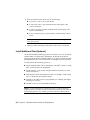
To open a drawing template (DWT) file
1 Click the Application menu button ➤ Open.
2 In the Select File dialog box, select Drawing Template (*.dwt) from the
Files of Type drop-down list.
3 Browse to and select the drawing template (DWT) file you want to modify.
4 Click Open.
5 Make the desired changes to the DWT file.
6 Click the Application menu button ➤ Save.
What are the benefits of customizing AutoCAD?
Customizing AutoCAD provides many benefits that can increase your
productivity and make your drawings have a consistent appearance.
Customization can be as simple as creating a block that can be used in many
drawings over and over again, such as a title block, or customizing the user
interface with the Customize User Interface (CUI) Editor. For information
about customizing the user interface, see Work with the Customize User
Interface (CUI) Editor in the Customization Guide.
How do I modify drawing templates at a later time? | 37
38
Network Administration
and Deployment
3
Network administration and deployment requires careful planning and execution. This section
gives you information about how to prepare for deployment, set up and customize a
deployment, and distribute the program.
Preparing a Deployment
To prepare for a deployment, you should take the time to review the following
requirements and options.
System Requirements for Administrative Image
This section contains the system requirements for the location of the
administrative image.
Before you begin installing the program on a network, make sure that your
servers and client workstations meet the minimum recommended hardware
and software requirements for a deployment. For complete system requirements,
see System Requirements on page 1.
The program will automatically detect if the Windows operating system is the
32- or 64-bit version when installing AutoCAD. The appropriate version of
AutoCAD will be installed. The 32-bit version of AutoCAD cannot be installed
on a 64-bit version of Windows vice-versa.
39
See the following tables for administrative image system requirements.
Hardware and Software Requirements - Administrative Image Location
Hard disk
2 GB or above (recommended)
The location where you create the administrative image must be a shared location so
that users can access the administrative
image.
Choose an Installation Type
When you set up your deployment, you need to choose the type of installation
to deploy. In the AutoCAD Deployment wizard, you specify one of the
following installation types:
Stand-Alone installation (Stand-Alone option) Choose this type of
installation for stand-alone installations where a single serial number and
product key are used for a single seat. Like a multi-seat stand-alone installation,
you do not use the Network License Manager to manage product licensing,
but installation, registration, and activation occurs on each workstation.
Multi-Seat Stand-Alone installation (Stand-Alone option) Choose this type
of installation for stand-alone installations where a single serial number and
product key are used for multiple seats. Multi-seat stand-alone installations
do not rely upon the Network License Manager to manage product licenses;
however, you can still use the AutoCAD Deployment wizard to create
administrative images and deployments. Registration and activation is more
automated for multi-seat stand-alone installations. After the first activation
using the multi-seat stand-alone serial number and product key, activation
occurs automatically for all workstations based on this deployment, as long
as your systems are connected to the Internet.
Network License installation With this type of installation, you install the
program to workstations with the files and registry entries that allow the
program to communicate with the Network License Manager. You also define
the configuration of the Network License Manager so that the licenses can be
accessed. Workstations running the program based on a network installation
do not require individual activation. Licensing of this program is managed
by at least one license server.
The main advantage is that you can install AutoCAD on more systems than
the number of licenses you have purchased (for example, purchasing 25
licenses but installing on 40 workstations). At any one time, AutoCAD runs
40 | Chapter 3 Network Administration and Deployment
on the maximum number of systems for which you have licenses. This means
you get a true floating license.
Choose a License Server Model
If you chose the Network License option, you need to decide which license
server model to use to distribute the product licenses.
TIP If you are deploying a stand-alone or multi-seat stand-alone installation type,
you do not use a license server model.
For the network installation, use one of the following license server models:
■
Single license server model. The Network License Manager is installed on
a single server, so license management and activity is restricted to this
server. A single license file represents the total number of licenses available
on the server.
■
Distributed license server model. Licenses are distributed across more than
one server. A unique license file is required for each server. To create a
distributed license server, you must run the Network License Manager on
each server that is part of the distributed server pool.
■
Redundant license server model. You use three servers to authenticate a
single license file. One server acts as the master, while the other two provide
backup if the master server fails. With this configuration, licenses continue
to be monitored and issued as long as at least two servers are still functional.
The license file on all three servers is the same. You must install the
Network License Manager on each server.
Each of these license server models is described in detail in the Autodesk Licensing
guide. It is strongly recommended that you also read that guide before you
deploy the program. You can find Autodesk Licensing guide by clicking the Read
the Documentation selection, the Documentation link at the lower-left corner of
the deployment wizard, or in the Help system.
Create a Network Share
Once you have fully prepared for creating a deployment, you are ready to set
up and distribute AutoCAD by creating a network share location (folder). A
network share is an installation folder that you make available to users'
computers on a network. You point users to this location to install the program.
Choose a License Server Model | 41
A network, shared folder is required for network license and multi-seat
stand-alone methods of installation. Any subfolders that are placed inside a
network shared folder are automatically shared.
NOTE You must have Full Control permissions set for your shared folder when
you are creating your deployment images. Read permissions are necessary to
access the network share and administrative permissions on the workstation where
the program is deployed.
To create a network share folder
1 On your network server’s desktop, create a folder named Deployments.
2 Right-click the Deployments folder and click Share and Security (or Sharing).
3 In the <folder name> Properties dialog box, Sharing tab, select Share This
Folder.
4 Specify a Share Name, such as Deployments, if necessary.
5 Click the Permissions button. In the Permissions dialog box enter your
group or user names, and make sure Full Control is selected. Click OK.
In Vista, right-click the Deployments folder and then click Share. In the
File Sharing dialog box type in or browse to the name of the group or
user you want to share the folder with. Click Add, and then click Share.
6 For each product you plan to install, create a subfolder in the Deployments
folder. Name each folder with the pertinent product name.
Network Tools and Your License Server
If users are running the program using network licenses, you need to use the
Network License Manager. The Network License Manager helps you configure
and manage license servers. For information about installing and setting up
the Network License Manager and licensing tools, see the Autodesk Licensing
guide.
Setting Up and Creating a Deployment
The deployment process provides you with numerous options for creating,
and customizing your deployments, so you should set aside ample time to
complete the process in one sitting. To be successful, it is recommended that
you review the following checklist and information before you begin. The
42 | Chapter 3 Network Administration and Deployment
deployment process is initiated from the installation wizard’s Create
Deployments selection. Once a deployment is created, users then access the
deployment to install products to their computers.
Prepare for a Network Deployment
Complete the following preliminary tasks before creating a network
deployment.
Deployment Checklist
Review the system requirements. Confirm your network, servers, and client
workstations meet the system requirements.
Understand the type of license you have purchased. For a network license deployment, you should also be familiar with the type of license server model you
want to use, and the license server name(s).
Install and activate any support tools and utilities.
Locate your product serial number and product key. These are located on the
outside of the product packaging, or in the Autodesk Upgrade and Licensing
Information email message.
Determine how you intend to personalize the program(s) during registration.
Using consistent registration data is very important.
Identify the location, and create a shared folder where deployments will reside
for each program you plan to deploy.
Close all other programs and disable anti-virus software.
Decide which language to use for each of your deployment packages.
NOTE Languages can be included only during the creation of the deployment,
not during modification.
Determine whether your deployment plan involves using imaging software to
distribute your program(s) to client workstations.
Prepare for a Network Deployment | 43
Deployment Checklist
Determine whether to create log files that contain deployment and installation
data, and whether to run silent mode.
NOTE When the program is installed from a deployment using silent mode,
users’ systems automatically reboot without warning when the installation is
complete.
Determine an installation type (Typical or Custom), and whether to install Express
Tools (if applicable).
Determine the name and location for the installation folder, and the locations
for your support file content.
Determine your defined search paths and file locations.
Determine whether to include additional files with your deployment, such as
drawing files, AutoLISP routines, or script files.
Determine your user preferences—including whether to display the Welcome
Screen, whether to require Internet Explorer, the default publishing format, and
whether to create a desktop shortcut.
Check for service packs that might be available for your product.
Configure access to Communication Center. Live Update notifications let you
know when product updates are posted and configuring Communication Center
lets users access technical information.
Set up access to online resources, such as DesignCenter, Subscription Center,
Help, Customer Error Reporting, and InfoCenter search settings.
Configure Individual Products
You can create a deployment that uses the default product settings, or you
can configure each product to be included in the deployment. To configure
a product, on the Create Deployment page of the deployment wizard, select
the appropriate product from the drop-down list, and click Configure.
44 | Chapter 3 Network Administration and Deployment
The following configuration options are available. See Your Deployment
Choices on page 46 for details about these options.
■
Select the License Type (Stand-alone or Network license)
■
Select the Installation Type (Typical or Custom)
■
Install Express Tools
■
Select Installation Folders for Support Content
■
Define Search Paths and File Locations
■
Install Additional Files
■
Specify User Preferences
■
Include Service Packs
■
Configure InfoCenter Communication Center
■
Configure Access to Online Resources
When you finish selecting options, click Configuration Complete. The Create
Deployment page is redisplayed, where you can confirm your selections. Click
Create Deployment.
NOTE To retain a copy of your settings, click Copy to Clipboard.
If you do not want to make configuration changes on the Create Deployment
page, click Create Deployment. Then click Yes to continue creating your
deployment using the default configuration.
Configure Individual Products | 45
Your Deployment Choices
When you create a deployment, you will make several choices during the
process to create various client deployment images and deployment types.
The following sections outline your choices in more detail.
Enter User and Product Information
The User and Product Information page is used to personalize the program
for your environment. The information you enter is permanently retained
with the product and is displayed in the Help menu on all workstations.
Because you can't change this information later without uninstalling, take
care when entering the information.
You must also enter the product serial number and product key in order to
run the product. The serial number and product key are located on the outside
of the product packaging, or in the Autodesk Upgrade and Licensing
Information email. The serial number must contain a three-digit prefix followed
by an eight-digit number. The product key consists of five characters.
Your clients can review this product information later, on the InfoCenter
toolbar, click the drop-down arrow next to the Help button (the question
mark). Then click About - Product Information.
46 | Chapter 3 Network Administration and Deployment
Creating Log Files
From the General Deployment Settings dialog, you can setup two types of log
files with which you can monitor information about deployments and
installations.
■
Create network log The network log file keeps a record of all workstations
that run the deployment. On the General Deployment Settings page, you
choose whether or not to create a network log file. The log lists the user
name, workstation name, and the status of the installation. Refer to this
file for status information and details about problems that users
encountered during installation (for example, low disc space or inadequate
permissions).
The network log is named with the same name you chose for your
deployment. You can specify where the log file is created by entering either
a valid UNC (universal naming convention) path or hard-coded path on
your network, for example \\MyComputer\Autodesk\<Autodesk product>.
Users should use their actual computer name in place of MyComputer.
NOTE The folder where the network log resides must be a shared folder where
users who install the program have Change permissions. Otherwise, successes
or failures for user installations cannot be written to the log file.
■
Create client log The client log contains detailed installation information
for each workstation. This information may be useful in diagnosing
installation problems. The client log is located in the %Temp% directory
of each client workstation.
What Is Silent Mode?
When silent mode is active and a user initiates the deployment, the installation
proceeds without any explicit user input. Users cannot change any of your
Your Deployment Choices | 47
installation settings. No dialog boxes are presented that require interaction
from the user.
WARNING When the product is installed from a deployment using silent mode,
users’ systems will reboot automatically and without warning when the installation
is complete.
Select a License Type (Optional)
When you set up your deployment, you choose the type of installation to
deploy based on the type of software license you purchased: stand-alone or
network. You also select the network license server model you want to use to
distribute product licenses.
NOTE Depending on the type of option you choose on the configuration page,
stand-alone or network license, note that you must use the same type of installation
for all those products in your deployment session. If you select products that do
not support the type of license you purchased, you will not be able to activate
those products.
Specify the license type to use during deployment
Stand-alone license (a single serial number for a single seat) For a
stand-alone license, you install, register, and activate the program on each
workstation.
Network license With this type of installation, you install the program to
workstations with the files and registry entries that allow the program to
communicate with the Network License Manager. You also define the
configuration of the Network License Manager so that the licenses can be
accessed. Workstations running the program based on a network installation
do not require individual activation. Licensing of this program is managed
by at least one license server.
To deploy a stand-alone license
1 While creating a deployment, on the Select the License Type page, select
Stand-alone License.
48 | Chapter 3 Network Administration and Deployment
2 Click Next.
Specify the license server model during deployment
If you choose the Network License option, you need to decide which license
server model to use to distribute your product licenses - single, distributed or
redundant license server model. For more information about license server
models, see Choose a License Server Model on page 41.
If you are deploying a stand-alone or multi-seat stand-alone installation type,
you do not use a license server model.
To deploy a network license using a single license server model
1 While creating a deployment, on the Select the License Type page, select
the Network license option.
2 Select Single License Server as the license server model you want to use
with the Network License Manager.
If you have already used the Network License Manager to create a license
server model, you must select the same license server model in this step.
If you have not yet used the Network License Manager to create a license
server model, make sure that you select the same settings in the Network
License Manager that you choose here.
3 Enter the server name of the server that will run the Network License
Manager, or click the Browse button to locate the server. Click Next.
Your Deployment Choices | 49
For more information about license server models and setting up your license
server, see Plan Your License Server Configuration in Autodesk Licensing.
To deploy a network license using a distributed license server model
1 While creating a deployment, on the Select the License Type page, select
the Network license option.
2 Select Distributed License Server as the license server model you want to
use with the Network License Manager.
If you have already used the Network License Manager to create a license
server model, you must select the same license server model in this step.
If you have not yet used the Network License Manager to create a license
server model, make sure that you select the same settings in the Network
License Manager that you choose here.
3 Enter the name of one of the servers that will run the Network License
Manager, or click the Browse button to locate the server. Click Add to
add the server to the Server Pool. Once all the servers are added to the
Server Pool list, use the Move Up and Move Down buttons to arrange the
servers in the order you want them to be searched by a user's workstation.
You must enter at least two servers. Click Next.
For more information about license server models and setting up your license
server, see Plan Your License Server Configuration in Autodesk Licensing.
To deploy a network license using a redundant license server model
1 While creating a deployment, on the Select the License Type page, select
the Network License option.
2 Select Redundant License Server as the license server model you want to
use with the Network License Manager.
If you have already used the Network License Manager to create a license
server model, you must select the same license server model in this step.
If you have not yet used the Network License Manager to create a license
server model, make sure that you select the same settings in the Network
License Manager that you choose here.
3 In the First Server Name field, enter a server name of one server that will
run the Network License Manager, or click the Browse button to locate
the server. Enter the server names for the remaining two servers that you
will use in the redundant server pool. Click Next.
50 | Chapter 3 Network Administration and Deployment
For more information about license server models and setting up your license
server, see Plan Your License Server Configuration in Autodesk Licensing.
Select the Installation Type (Optional)
As part of making your deployment choices, you select the type of installation
that users receive when they install the program, choose which optional tools
or features are included, and specify where the product is installed on each
workstation.
You choose the location where program files are installed on the client
workstation in the Product Install Path. To help decide where the product is
installed, a chart of drives and disc space is provided.
To deploy a typical installation, choose optional tools, and specify a product
location
1 During the deployment, on the Select the Installation Type page, select
Typical as the type of installation that you want.
2 Enter the path on the client workstation where you want to install the
program, for example C:\Program Files\Autodesk\<Autodesk product>.
Your Deployment Choices | 51
The Disc Space Requirements chart lets you review available drives and
disc space.
3 Click Next.
To deploy a custom installation, choose optional tools, and specify a product
location
1 During the deployment, on the Select the Installation Type page, select
the Custom option as the type of installation that you want.
2 From the Select Features to install list, select the features that you want
to install.
If, after making feature changes, you decide you want the original
selections, click the Restore Defaults button on the Select the Installation
Type page.
3 Enter the path on the client workstation where you want to install the
program, for example C:\Program Files\Autodesk\<Autodesk product>.
The Disc Space Requirements chart lets you review available drives and
disc space.
4 Click Next.
52 | Chapter 3 Network Administration and Deployment
Select Installation Folders for Support Content
On the Select Installation Folders for Support Content page, you choose where
your support content gets installed by specifying a folder other than the default
user profile folder used in previous releases. As a network administrator, these
options give you greater control over where you place support content during
installations or deployments.
Support files consist of six main types:
■
Support - Includes customization/menu files, palette content and hatch
and linetypes.
■
Plotters - Includes plot styles (.ctb files), and plot configuration files (.pc3
and .pmp files).
■
Data Links - Contains data links files.
■
Template - Includes drawing and Sheet Set templates, and Publish to Web
templates.
■
Rendering - Includes hardware certification information, and Web Light
files.
■
Help - Includes User’s Guide, Command Reference, New Features Workshop,
and various guides and learning resources.
Among the four options available, you can choose a single shared location,
local or network, where all your support content is installed. The illustration
and table below outline the other available options.
Your Deployment Choices | 53
There are four support content folder options:
Options
Notes
Local user profile folders
■
Texture maps installed to %ALLUSERSPROFILE%
■
All other content installed to %USERPROFILE%\Roaming AppData
■
No content stored in %USERPROFILE%\Local AppData
■
All content is installed to the AutoCAD installation folder on individual user station
■
User may need power user privilege to install AutoCAD
■
User may need power user privilege to run AutoCAD on a system
where support content is installed to the OS Program Files folder
■
Allows for a unique network path to be specified for all content
types
■
Subfolders for content types installed within this location
■
When a deployment is pushed to individual workstations, content
is copied into the network location only once when the deployment
is created
■
Allows a unique path to be specified for different content types
■
Supports local folders and UNC or mapped network paths
Program install folder
Single shared folder
Custom folders
An Overwrite Existing Files in Shared Network Folders check box is available
when either the Single Shared folder or Custom folder options is selected. If
the box is checked, the existing files in the chosen folder are overwritten. No
additional warning is given. If the box is unchecked, a warning message is
displayed.
54 | Chapter 3 Network Administration and Deployment
Define Search Paths and File Locations (Optional)
On the Define Search Paths and File Locations page, you can modify the
default search paths and the location of some program files. You might want
to modify the default settings for the following reasons:
■
If your environment uses a file (such as a customization file or plug-ins)
other than the default file that's installed with the program, you can point
to that file now and avoid having to add it at each workstation.
■
Some default file locations may have changed in this version of the
program. You can use this page if you have an earlier version of the
program, and you want to move the files to the same file location as your
earlier version.
To use the default program settings for search paths and file locations
■
While creating a deployment, on the Define Search Paths and File Locations
page, click Next.
To modify the default program settings for search paths and file locations
1 While creating a deployment, on the Define Search Paths and File
Locations page, in the Define Search Paths, File Names, and File Locations
list, click the plus sign (+) to the left of a search path or file location to
select and expand it.
Your Deployment Choices | 55
2 Select an item in the list and do any of the following:
■
To browse to a file location, click Browse.
■
To add a new entry to the currently selected search path or file
location, click Add.
■
To remove an entry from the currently selected search path or file
location, click Remove.
■
To move a selection up or down in the list, click Move Up or Move
Down.
NOTE The availability of these buttons depends on the item that you selected
in the previous step.
3 When you finish specifying search paths or file locations, click Next.
Install Additional Files (Optional)
On the Install Additional Files page, when you click Browse, you can specify
additional files to include with a deployment. By default, these files are
installed in the program's installation directory on client workstations when
the deployment is run. You can install files to multiple directories if desired.
You can perform the following operations:
®
■
Specify additional files (such as drawing files, AutoLISP routines, or script
files) to include with your deployment.
■
Install user files, of any format, and place them in any directory on the
client’s workstation.
■
Add subfolders under the installation folder (for example, a folder called
LSP to contain custom AutoLISP routines).
■
Add files to the same location as program files (for example, add sample
drawings for a project).
■
Add files to the root of the installation directory.
NOTE It is recommended that you install these files to a location within the
program's directory structure. You cannot install files with the same file name as
an installed program file. For example, you cannot add a file named acad.cui.
56 | Chapter 3 Network Administration and Deployment
To install additional files
1 While creating a deployment, on the Install Additional Files page, set the
location where the files will be installed.
2 Do any of the following:
■
Click Browse to open the Add Files dialog box, where you can select
files to add to the installation directory.
■
Click Add Folder to create a new folder in the installation directory.
■
Click Add Drive to add a drive name to the file location structure. The
drive name must be a valid drive letter and colon, for example C: or
F:. Uniform Naming Convention (UNC) paths are not supported.
■
Click Remove to delete a file, folder, or drive from the installation
directory.
3 Click Next.
Your Deployment Choices | 57
Specify User Preferences (Optional)
On the Specify User Preferences page, you specify:
■
Access to the Welcome Screen
■
Require Internet Explorer for installation
■
Set DWFx as the default publishing format
■
Set a default profile name
■
Display a desktop shortcut for AutoCAD, or create a custom shortcut
If you do not require Microsoft Internet Explorer to be installed before
AutoCAD is installed, then deselect the Require Internet Explorer for
installation.
Your default profile name is the name of all your users will see when they run
the deployment.
Clear the check box for Create a Desktop Shortcut for AutoCAD if you do not
want the product shortcut icon to appear on the user's desktop. If you want
to create a custom desktop shortcut, specify a shortcut name and any
parameters, such as switches that will call profiles, startup scripts, and so on.
58 | Chapter 3 Network Administration and Deployment
Include Service Packs (Optional)
You have the option to include service packs for your product. You can select
to download and apply a service pack from autodesk.com, or choose to use a
locally stored (local hard drive or local network) service pack. In either case,
the service pack will be applied only after the installation of the main product
is completed.
If you select the Install Service Pack from autodesk.com button, the service pack
will be automatically downloaded and you will not need to extract the MSP
file.
If you choose to include a service pack from a local or network drive, you will
need to plan how you want the service pack handled from the two options
below. You will also need to complete the following steps.
NOTE If the deployment process for the main product is canceled or fails, the
service pack installation will automatically be canceled.
■
Append the Service Packs onto the Deployment. When you append a
service pack, the service pack is applied to the current deployment only.
Multiple service packs may be appended to a deployment. The service pack
Your Deployment Choices | 59
file is included in the deployment and the service pack is applied after the
product is deployed.
■
Merge the Service Packs into the Administrative Image MSI File. When
you merge a service pack, the service pack is merged into the administrative
image. Once merged, a service pack may not be removed from the
administrative image. Multiple service packs may be included in a single
administrative image.
To extract a Microsoft Installer Patch (MSP) file from a service pack
1 Download the service pack from the AutoCAD support site.
2 Review the service pack Readme file for information about patch usage.
3 Open a Windows command prompt and enter the patch file name
followed by the /e switch and a target file name, such as:
ProductSP1.exe /e ./ProductSP1.msp
where <ProductSP1.exe> is the name of the downloaded patch and
<ProductSP1.msp> is the name of the extracted file. Using ‘./’ in front of
the extraction file name places the extracted file in the same folder as
the original executable. The “e” command line switch extracts the MSP
file from the executable.
To include a service pack with the deployment
To include a service pack with a deployment, an MSP file must be extracted
from the downloaded service pack executable.
1 On the Include Service Packs page, click the Browse button.
2 In the Open dialog box, locate the service pack you want to include with
the deployment.
3 Select the MSP file and click Open.
4 Specify whether you want to append the service pack to the deployment
or merge the service pack into the administrative image.
5 Click Next.
60 | Chapter 3 Network Administration and Deployment
Configure InfoCenter Communication Center (Optional)
The Communications Center is accessed through InfoCenter. Products are
updated with Live Update, which downloads patches to your product using
Communication Center. Beyond Live Update, other information channels
and feeds can be displayed by the Communication Center.
The Communication Center settings you can make include the following:
■
Enable Live Updates. Users can use Live Update to check for updates when
a Web connection is established. If a product patch is available, notification
of its availability is received on the program's status bar, and the patch can
be either downloaded directly from an Autodesk server or modified first
before being copied to users' workstations. If you don't want users to receive
updates or announcements, you can turn off Live Update.
NOTE You can also turn Live Update options on or off in the CAD Manager
Control utility.
■
Enable Information Channels. When active, information channels notify
users with various pieces of information such as product support
information.
■
Enable CAD Manager Channel. Controls the display of the CAD Manager
Channels in InfoCenter. Aside from being able to toggle CAD Manager
Your Deployment Choices | 61
Channels, you can also define the CAD Manager feed location and set the
display name for the CAD Manager Channel.
■
Enable RSS Feeds. Users can subscribe to any number of RSS feeds. Each
feed is contained within a discrete InfoCenter category. Additionally, you
can specify whether users can add RSS feeds.
To configure Communication Center
1 When creating a deployment, on the Configure InfoCenter
Communication Center page, make the following Live Update settings:
■
Enable Live Updates. Users can receive product updates or support
announcements from Autodesk servers.
■
Receive Live Updates from Autodesk. Users can receive product updates
and support announcements from Autodesk servers with Live Update.
■
Receive Live Updates from Local Server. You can maintain a patch
list on a local server. A patch list is an XML file that specifies a list of
patches available for installation on your computer.
If you select this option, the Local Patch List Location box is available.
Use the Browse button to locate the path to a server location where
you want a patch list. More information about how to use a local
patch list is available by installing Autodesk CAD Manager Tools,
running the CAD Manager Control utility, and then clicking Help in
the CAD Manager Control utility window.
NOTE You can name a file to use for patch information. By naming a file
and using an .npl extension now, you are creating a placeholder file, not
creating the file itself. In the location that you specify in the Local Patch
List Location box, you must create a text file with the same name you
specify here.
2 Specify whether Information channels should be enabled.
3 Specify whether CAD Manager channels should be enabled. When active,
you can make the following settings:
■
Feed Location. Defines the location of the CAD Manager channel RSS
feed. RSS feeds are in XML format.
■
Display Name. Sets the display name of the CAD Manager channel.
4 Specify whether RSS Feeds are enabled and if users are allowed to add
feeds.
62 | Chapter 3 Network Administration and Deployment
5 Click Next.
Allow Users to Access Online Resources (Optional)
On the Configure Access to Online Resources pages, you can specify whether
users can access online resources such as receiving live updates from Autodesk,
enabling information or CAD Manager channels, or subscribing to RSS feeds.
You can also allow access to the DesignCenter as well as specifying Customer
Error Reporting and InfoCenter settings.
DesignCenter
The DC Online tab in DesignCenter provides access to pre-drawn content
such as blocks, symbol libraries, manufacturers' content, and online catalogs.
This content can be used in common design applications to assist users in
creating drawings.
NOTE DesignCenter Online is not selected by default. If you choose not to enable
DC Online at the time of installation, you can enable it later from the CAD Manager
Control utility.
Subscription Center
With Autodesk Subscription, users receive the following:
■
Software upgrades and exclusive product downloads
Your Deployment Choices | 63
■
Access to training and learning materials
■
One-on-one product support
■
Exclusive license terms on any Autodesk products under contract
■
Access to Autodesk Knowledge Base
Online Help
Access to online Help documentation is available to your users from
www.autodesk.com. The Help system can also be installed during the product
installation process should you choose to restrict online access. Access to
online or local Help can also be done through the CAD Manager Control
utility.
The Help documentation includes User’s and Customization Guides, a
Command Reference, New Features Workshop, developer documentation,
learning and training tutorials, and other learning resources. A product Readme
is also available that contains late-breaking information on your product.
Customer Error Reporting (CER)
If your Autodesk product closes unexpectedly, users have the opportunity to
send an error report directly to Autodesk, which helps Autodesk to determine
and resolve the error. You can determine whether users can also receive
notification from Autodesk when their reported errors are resolved.
NOTE You can also turn Customer Error Reporting notification on or off in the
CAD Manager Control utility.
Specify InfoCenter Search Settings
The Search Results tab of InfoCenter can be configured to display content
from various sources, such as the product Help system, CAD Manager
Channels, or the Internet.
64 | Chapter 3 Network Administration and Deployment
You can specify whether users who install from the deployment can customize
access to their InfoCenter search locations.
To configure access to online resources
1 While creating a deployment, on the Configure Access to Online Resources
page, do the following to configure DesignCenter Online:
■
To enable DesignCenter Online, select the check box next to Enable
DC Online.
2 If you want to receive notification of problem resolutions, do the
following:
■
Select the check box next to Allow Users to Receive Notification of
Resolution so that users are made aware of resolutions to issues and
can download applicable updates provided by Autodesk. This option
is enabled by default.
NOTE Users must have administrative permissions to install an update
provided by Autodesk.
■
Select the check box next to Include Computer Name to include the
user’s computer name in error reports. The computer name is included
in notifications to the user and in reports available to subscription
administrators. This option is disabled by default.
3 Specify whether users have the option to customize their InfoCenter
search locations. This option is enabled by default.
4 Click Configuration Complete.
Create a Default Deployment
If you do not plan to customize your deployment, you can create a default
deployment.
The following procedure illustrates how quickly you can set up a default
deployment using the deployment wizard. This procedure illustrates a
single-server network deployment using a Typical installation with no
customizations. For information about customizing product configurations in
a deployment, see Create a Custom Deployment on page 67.
Create a Default Deployment | 65
To create a deployment using default settings
1 Start the AutoCAD Installation wizard.
2 On the initial page, select a language for the deployment instructions.
Click Create Deployments.
3 On the Begin Deployment page, specify the following:
■
Administrative Image Field. Enter or locate the path to the shared network
location where you want to create and store your administrative image.
Users install the program from this location.
NOTE For information on how to create a network share, see Create a
Network Share on page 41.
■
Deployment Name Field. Enter the new deployment's name. This name
is used for the shortcut from which users will install the product.
■
This is to be a: Select either 32-bit or 64-bit for your target operating
system.
Click Next.
4 On the Select the Products to Include in the Deployment page, select the
products, and language to include in your deployment. Click Next.
5 Review the Autodesk software license agreement. Click I Accept, and then
click Next.
6 On the User and Product Information page, enter your user information,
serial number, and product key. Click Next.
WARNING After you click Next, you cannot change the information entered
on the this page unless you uninstall the product.
7 On the General Deployment Settings page specify whether to
■
Create a network log file. Specify the log file’s location by entering
either a valid UNC (universal naming convention) path or a
hard-coded path on your network.
NOTE The folder that contains the network log file must be a shared
folder for which users who install the program have Change permissions.
Otherwise, successes or failures for user installations cannot be written to
the log file.
66 | Chapter 3 Network Administration and Deployment
■
Create a client log file.
■
Run the installation in silent mode to prevent users from changing
installation settings.
For more information on log files, see Creating Log Files on page 47. For
more information on silent mode, see What Is Silent Mode? on page 47.
Click Next.
8 On the Create Deployment page, click Create Deployment. Click Yes to
continue creating the deployment using the default configuration.
An administrative image is created in your shared folder using the
deployment options listed in Current Settings. To retain a copy of your
deployment settings, click Copy to Clipboard.
9 On the Deployment Complete page, click Finish.
Create a Custom Deployment
To alter your deployment by removing features or restricting access to online
resources, customize the configuration of each product included in the
deployment.
To create a custom deployment
1 Start the AutoCAD Installation wizard.
2 On the initial page, select a language for the deployment instructions.
Click Create Deployments.
3 On the Begin Deployment page, specify the following:
■
Administrative Image Field. Enter or locate the path to the shared network
location where you want to create and store your administrative image.
Users install the program from this location.
NOTE For information on how to create a network share, see Create a
Network Share on page 41.
■
Deployment Name Field. Enter the new deployment's name. This name
is used for the shortcut from which users will install the product.
■
This is to be a: Select either 32-bit or 64-bit for your target operating
system.
Create a Custom Deployment | 67
Click Next.
4 On the Select the Products to Include in the Deployment page, select the
products, and language to include in your deployment. Click Next.
5 Review the Autodesk software license agreement. Click I Accept, and then
click Next.
6 On the User and Product Information page, enter your user information,
serial number, and product key. Click Next.
WARNING After you click Next, you cannot change the information entered
on the this page unless you uninstall the product.
7 On the General Deployment Settings page specify whether to
■
Create a network log file. Specify the log file’s location by entering
either a valid UNC (universal naming convention) path or a
hard-coded path on your network.
NOTE The folder that contains the network log file must be a shared
folder for which users who install the program have Change permissions.
Otherwise, successes or failures for user installations cannot be written to
the log file.
■
Create a client log file.
■
Run the installation in silent mode to prevent users from changing
installation settings.
For more information on log files, see Creating Log Files on page 47. For
more information on silent mode, see What Is Silent Mode? on page 47.
Click Next.
8 On the Create Deployments page, click Configure to customize the
product configuration.
9 On the Select the License Type page, select Stand-alone or Network license,
and click Next.
68 | Chapter 3 Network Administration and Deployment
10 On the Select the Installation Type page, specify the following:
■
Installation Type. Select Typical to install the most common application
features. Custom to install only the application features that you select
from the Select Features To Install list.
■ The following table lists features that are available for selection with
a custom installation.
CAD Standards
Contains tools for reviewing design files for compliance with
your standards.
Database
Contains database access tools.
Dictionaries
Contains multi-language dictionaries.
Drawing Encryption
Allows you to use the Security Options dialog box to protect
a drawing with a password.
Express Tools
Contains AutoCAD support tools and utilities (not supported
by Autodesk).
Fonts
Contains AutoCAD fonts and TrueType fonts.
Autodesk Seek
Autodesk Seek.
NOTE Seek will only be installed in the English version
of AutoCAD.
Welcome Screen
Contains learning resources to help discover the product.
License Transfer Utility
Allows users to transfer an Autodesk product license between
computers.
NOTE The utility will not be installed on unlocked versions of AutoCAD.
Migrate Custom Settings
Migrates custom settings and files from previous version of
your product to this version.
Initial Setup
Allows users to perform some basic customization of AutoCAD
(online content, workspaces) based on their units system, industry, and commonly used task-based tools.
Create a Custom Deployment | 69
Reference Manager
Allows users to view and edit the paths of externally referenced
files associated with a drawing.
Samples
Contains various feature sample files.
Tutorials
Contains tutorials.
■
Install Optional Tools. Specify whether to install AutoCAD Express Tools
Volumes 1-9 which contains a library of productivity tools designed
to help you extend the power of AutoCAD.
■
Product Install Path. Specify the drive and location where you want to
install the product.
Click Next.
11 On the Select Installation Folders for Support Content page, choose the
location for your support content. For more information about support
file locations and options, see Select Installation Folders for Support
Content on page 53. Click Next.
12 On the Define Search Paths and File Locations page, specify the necessary
search paths, file names, and file locations. Click Next.
WARNING Do not remove the DRV path. Always add paths as secondary
paths.
13 On the Install Additional Files page, specify the installation location and
the filesnames of any additional files you want to include in the
deployment. Click Next.
14 On the Specify User Preferences page, specify whether to display the
Welcome Screen, whether to require Internet Explorer, the default publish
format, the default profile name, and whether to create a desktop shortcut.
Click Next.
15 On the Include Service Packs page specify whether to include any available
service packs. The installer automatically checks autodesk.com for available
updates.
16 On the Configure InfoCenter Communications Center page, specify
whether to allow users access to the latest information and product
discussions through live updates from Autodesk, Information and CAD
Manager channels, and RSS feeds. Click Next.
70 | Chapter 3 Network Administration and Deployment
17 On the Configure Access to Online Resources page, you can set up access
to online tools such as DesignCenter, Subscription Center, and Online
Help. You can also specify Customer Error Reporting settings, and allow
users to customize InfoCenter searches. Click Next.
18 On the Configuration Complete page, select a product tab to configure
another product, or click Configuration Complete to review your settings.
19 On the Create Deployment page, click Create Deployment. To retain a
copy of your deployment settings, click Copy to Clipboard.
20 On the Deployment Complete page, click Finish.
Modify a Deployment (Optional)
After a deployment is created, it may be necessary to modify the deployment
for some client workstations. You can apply a patch or include various custom
files that are not part of the base administrative image. You can also perform
modifications such as changing the installation directory from drive C to drive
D.
To modify a deployment
1 Open the shared network folder where you originally chose to place your
product deployment.
2 In the Tools folder, double-click the Create & Modify a Deployment
shortcut.
The deployment wizard is redisplayed.
3 Click through the deployment pages and make the necessary changes.
4 Click Create Deployment.
Point Users to the Administrative Image
When you are done creating the deployment, users can install the program
using the shortcut located with the administrative image. The shortcut name
matches the deployment name that you specified in the deployment wizard.
Notify users of the location of the administrative image, instruct them to
double-click the shortcut, and provide any other necessary instructions.
Modify a Deployment (Optional) | 71
72
Distributing an Autodesk
Program
4
You can choose from several methods of distributing an Autodesk program. Network sharing
is the default method.
Use Scripts to Deploy the Program
A script executes a command or a set of commands. Scripts are similar to batch
files but are more flexible. Installation scripts are most useful for stand-alone
installation of programs on computers that are connected to a network. Scripts
are also useful for installing service packs, extensions, and object enablers on a
network.
You create a script by using a text editor such as Notepad and then saving it in
ASCII format in a file with the file extension .vbs. The script consists of one or
more commands, as well as command switches that specify options, and flags
that modify the options. An installation script also contains path names.
An installation script points to the location of the product's setup.exe file. You
must point to the setup.exe file on your product disc. For example:
Autodesk product CDROM1\setup.exe
In order for AutoCAD to run properly, the following software and prerequisites
must be installed and met on the computer where the program is being installed:
■
Microsoft Internet Explorer version 6.0 Service Pack 1 or later (You can
download Microsoft Internet Explorer from the Microsoft website by visiting
www.microsoft.com)
■
Microsoft Scripting Engine
73
The sample scripts in this section are based on Microsoft Scripting Engine
5.6, which works with both VBScripts and JavaScript. If you don't have
the scripting engine installed, you can download it for free from the
Microsoft website at www.msdn.microsoft.com/scripting. Sample scripts and
Help files are also available there for download.
■
Administrative permissions
A Sample Installation Script
The sample script in this section installs the program in a typical configuration.
To make it easy to copy this sample script and substitute your own information,
the same names are used throughout for variable items. The log file name is
based on the product being installed. You can either use the log file name in
the script or change it to something else.
Serial number prefix: 123
Serial number: 12345678
First name: My First Name
Last name: My Last Name
Organization: Organization
A sample script for a silent installation of this program uses the syntax shown
in this section.
Scripted installation for the AutoCAD
' Scripted installation for AutoCAD 2011 - English
option explicit
'
74 | Chapter 4 Distributing an Autodesk Program
' Create variables
dim shell
dim productType
dim strADSKFirstName
dim strADSKLastName
dim strADSKOrganization
dim strADSKSNPrefix
dim strADSKSNNumber
dim strADSKProdKey
dim strLocale
dim strACADStandaloneNetworkType
dim strADSKLicenseServerType
dim strADSKLicenseType
dim strADSKServerName
dim strADSKServerPath
dim strADSKServerHostID
dim strADSKPath
dim strSourcePath
'
A Sample Installation Script | 75
' Script initialization
Set shell = CreateObject("WScript.Shell")
productType = "ACAD"
'
' Name and Organization information
strADSKFirstName = "My First Name"
strADSKLastName = "My Last Name"
strADSKOrganization = "Organization"
'
' Serial Number information
strADSKSNPrefix = "123"
strADSKSNNumber = "12345678"
strADSKProdKey="ABCDE"
'Locale information, for example en-US = US English, de-DE =
Deutchland German, ja-JP = Japan Japanese
strLocale="" ' en-US, de-DE, ja-JP
'
' Source to install from (e.g. D: is assumed to be Install Media)
strSourcePath = "D:\"
'
' Destination to install to
strADSKPath = Shell.ExpandEnvironmentStrings("%ProgramFiles%") +
“\Autodesk\” + "AutoCAD 2011"
If strLocale <> "" Then strADSKPath = strADSKPath + " " + strLocale
strADSKPath = strADSKPath + "\"
'''''' Uncomment the relevant version of your installation - De
fault is Standalone
' For Standalone
RunStandaloneInstall()
'
' For Single Network License Server
'RunSingleLicenseServerInstall()
'
' End of Script
Wscript.quit()
'
76 | Chapter 4 Distributing an Autodesk Program
Function RunStandaloneInstall
shell.run DefaultCommand(),2,1
end function
'
Function RunSingleLicenseServerInstall
' Update with the correct information for the license server
strACADStandaloneNetworkType = "3"
strADSKLicenseServerType = "Single Server License"
strADSKLicenseType = "Network License"
strADSKServerPath = "myFlexNetServer"
' HOSTID or MAC address
strADSKServerHOSTID = "000000000000"
'
' Consolidate the two values
strADSKServerPath = strADSKServerPath & " " & strADSKServerHOSTID
shell.run MakeCommand(),2,1
end function
'
A Sample Installation Script | 77
Function DefaultCommand
dim retString
' /qb for silent install ' /c [key] override parameters for the
key
' /w wait until installation completes before returning to script
' /o reboot after install completes
retString = """" & strSourcePath & "\setup.exe" & """" & " /t /qb
"
If strLocale <> "" then
retString = retString & "/Language " & strLocale
End if
retString = retString & " /c " & productType & ": "
retString = retString & "INSTALLDIR=" & """" & strADSKPath & """"
& " "
retString = retString & "ACADSERIALPREFIX=" & strADSKSNPrefix & "
"
retString = retString & "ACADSERIALNUMBER=" & strADSKSNNumber & "
"
retString = retString & "ADLM_PRODKEY=" & strADSKProdKey & " "
retString = retString & "ACADFIRSTNAME=" & """" & strADSKFirstName
& """" & " "
retString = retString & "ACADLASTNAME=" & """" & strADSKLastName
& """" & " "
retString = retString & "ACADORGANIZATION=" & """" & strADSKOrgan
ization & """" & " "
retString = retString & "InstallLevel=5 "
DefaultCommand = retString & " "
end function
'
78 | Chapter 4 Distributing an Autodesk Program
Function MakeCommand
dim retString
retString = DefaultCommand() & " "
retString = retString & "ACADSTANDALONENETWORKTYPE=" & """" &
strACADStandaloneNetworkType & """" & " "
retString = retString & "ACADLICENSESERVERTYPE=" & """" & strADSK
LicenseServerType & """" & " "
retString = retString & "ACADLICENSETYPE=" & """" & strADSKLicense
Type & """" & " "
retString = retString & "ACADSERVERPATH=" & """" & strADSKServer
Path & """" & " "
MakeCommand = retString
end function
Use Switches and Flags in Scripts
The following table lists all of the switches and flags that are relevant to
installation.
NOTE You must set the installation switch to INSTALLDIR=. If this is not done,
programs that run outside AutoCAD (such as the License Transfer utility) are not
installed.
Switches in Installation Scripts
Switch
Description
INSTALLDIR=
Specifies the location to install the product.
ACADSERIALPREFIX=
Specifies the numbers that precede the hyphen
in the serial number.
ACADSERIALNUMBER=
Specifies the serial number.
INSTALLLEVEL=
Specifies the type of installation: 3=Typical
ACADFIRSTNAME=
Specifies the first name personalization.
ACADLASTNAME=
Specifies the last name personalization.
ACADORGANIZATION=
Specifies the company name.
Use Switches and Flags in Scripts | 79
Switches in Installation Scripts
Switch
Description
ADLM_PRODKEY=
Specifies the product key (found on the same label
as the serial number).
User Interface Flags
Flag
Description
q
Designates that the installation is performed in silent mode.
Run Scripts
After creating a script, you move it to a server or use a mapped drive letter or
a UNC (universal naming convention) path. If you place it on a server for
users to run, create a share on the server, and then add users to the share with
the rights they need. Because all that users need to do is run the script, provide
read-only access to the share directory.
Next (on the same server or on a different server), create a directory for each
product you want to install. Choose a location for this directory that won't
be changed so that you can point to the MSI files in your scripts. Copy the
product disc(s) to that directory. You may also want to create directories for
service packs, extensions, and your own customization tools.
You can use any of the following methods to run an installation script:
■
Run the script manually at each individual workstation. To run the
installation, paste the script into the Run dialog box or run it from the
Windows command prompt.
■
Send an email with the UNC path to each user who should run the script.
To run the script, the user follows your instructions.
■
Email the script to each user with instructions for use.
■
Set up the script so that it runs on login.
Use Group Policies to Run a Deployment
With group policies, you can advertise and install a program by assigning a
deployment to computers. A deployment that is assigned to a computer can
80 | Chapter 4 Distributing an Autodesk Program
be used by any user of that computer. Generally, you would assign the
deployment to a computer that is used by a large number of users.
NOTE Autodesk products are designed to be installed on a computer so that any
user who logs on to the computer can run the software. If you assign a deployment
to a specific user rather than a computer, you may encounter problems when a
second specified user tries to install or uninstall a copy of the program.
The following outlines the advantages and disadvantages of using group
policies.
Advantages
■
Works well with deployment functionality.
■
Allows you to add custom files through the deployment wizard.
■
Allows deployment to workstations.
Disadvantages
■
Prohibits the passing of command-line parameters to an MSI executable.
You must use scripts instead.
■
Prohibits customization of application settings, other than what is set
while creating a deployment.
In order for AutoCAD to run properly, the following software must be installed
on the computer where the program is being installed:
Available on the product disc
Microsoft .NET 3.5 SP1
DirectX 9.0C
VC++ 2008 SP1 and VC++2005 SP1 runtimes for x86 operating systems; VC++2008 SP1
and VC++2005 SP1 runtimes for x64 for 64-bit operating systems
Microsoft National Language Support Downlevel APIs
FARO LS
Autodesk Design Review 2011 (Not installed by default)
Use Group Policies to Run a Deployment | 81
Macromedia Flash Player 9.0 or later (Not installed by default)
Autodesk Material Library 2011(CM)
Autodesk Material Library 2011 Base Image Library (ILL)
Other
Microsoft Internet Explorer version 7.0 Service Pack 1 or later. You can download Microsoft Internet Explorer from the Microsoft website by visiting www.microsoft.com.
Microsoft Installer Package (MSI) 4.5
Microsoft Windows Media Format 9.5 (prerequisite for 64-bit)
There are three main steps to distributing this program through group policies.
■
Create an application distribution share point. The application distribution
share point is created using the deployment wizard. See Create a Default
Deployment on page 65 or Create a Custom Deployment on page 67 to
create a deployment.
■
Assign the deployment to a computer. See Use Group Policies to Assign a
Deployment to Computers on page 82.
■
Verify the installation. Confirm that the program has been correctly
installed. See Verify a Group Policy Deployment on page 88.
Use Group Policies to Assign a Deployment to
Computers
Perform the following procedures from a Windows XP workstation or a
Windows 2000 or 2003 server that has Group Policy Management Console
installed, and has access to the Active Directory server.
NOTE For more information about Group Policy Management, see
http://technet.microsoft.com/en-us/windowsserver/grouppolicy.
To assign a deployment to a computer
1 Start the Group Policy Management Console (gpmc.msc).
82 | Chapter 4 Distributing an Autodesk Program
2 Right-click the organizational unit where you want to create the group
policy object. Then select Create and Link a GPO Here and name the
Group Policy.
3 Edit the policy.
4 In the Group Policy Object Editor dialog box, under Software Settings,
right-click Software Installation, and click New ➤ Package.
5 In the Open dialog box, navigate to the administrative image’s location
that you specified in the deployment wizard. Navigate to
AdminImage\<processor type>\<product name folder>. The processor type is
either x86 or x64, depending on the processor type for which you created
your deployment.
Examples
For x86 deployments:
\\server123\Deployment\AdminImage\x86\acad
For x64 deployments:
\\server123\Deployment\AdminImage\x64\acad
6 Select the Windows Installer Packages file called acad-<deployment
name>-for-GPO.msi. Click Open.
If the deployment was called “AutoCAD 2011 32 bit,” then the
deployment’s the MSI file would be acad-AutoCAD 2011 32 bit-for-GPO.msi.
Use Group Policies to Assign a Deployment to Computers | 83
7 In the Deploy Software dialog box, select Advanced and click OK.
8 In the Properties dialog box, Modifications tab, click Add.
9 In the Open dialog box, select the Transform Package file called
acad-<deployment name>.mst). Click Open.
10 In the Properties dialog box, Modifications tab, click Add.
11 In the Open dialog box, navigate to <deployment location>\Tools and select
the Transform Package file called gpo.mst.
84 | Chapter 4 Distributing an Autodesk Program
After clicking Open, the Properties dialog should look like the following:
12 Click OK to complete the package.
Use Group Policies to Assign a Deployment to Computers | 85
Adding a Language Pack
Next, you will need add a language pack to your package.
To add a language pack
1 In the Group Policy Object Editor dialog box, under Software Settings,
right-click Software Installation for the same object, and then click New
➤ Package.
2 In the Open dialog box, navigate to the administrative image’s location
you specified in the deployment wizard. Navigate to AdminImage\<processor
type>\<locale>\acad. Click Open.
The <locale> used in the examples is en-us for US English.
Examples
For x86 deployments: \\server123\Deployment\AdminImage\x86\en-us\acad
For x64 deployments: \\server123\Deployment\AdminImage\x64\en-us\acad
3 In the Deploy Software dialog box select Advanced and click OK.
4 In the <product name> Properties dialog box, Modifications tab, click Add.
5 In the Open dialog box, select the Transform Package file called
acad-<deployment name>.mst located at AdminImage\<processor type>\acad.
Click Open.
6 In the <product name> Properties dialog box, Modifications tab, click Add.
7 In the Open dialog box, navigate to <deployment location>\Tools and select
the Transform Package file called gpo.mst.
After clicking Open, the Properties dialog box should resemble to the
following:
86 | Chapter 4 Distributing an Autodesk Program
8
9 Click OK to complete the package.
Your final group policy object should resemble the following:
Use Group Policies to Assign a Deployment to Computers | 87
The group policy object is now assigned to all computers that are members
of the organizational unit for which the group policy object has been created.
The next time a computer in the organizational unit is restarted, the program
will be installed and will be available for all users of the computer. See Verify
a Group Policy Deployment on page 88 to confirm that the group policy has
been created correctly.
Verify a Group Policy Deployment
To verify that this deployment has been correctly assigned to a computer,
restart a computer that is in the organizational unit for which the group policy
was created. The program installation begins before the login prompt is
displayed. The operating system displays group policy messages, including a
message indicating the installation of any managed software.
After logging in, double-click the program icon on the desktop to complete
the installation and start the program.
NOTE If problems arise, an entry is logged in the system's Event Viewer under
Applications.
88 | Chapter 4 Distributing an Autodesk Program
Use Microsoft System Center Configuration
Manager to Install a Deployment
The following information provides details for deploying Autodesk software
using Microsoft® System Center Configuration Manager (SCCM). SCCM allows
you to manage software distribution to selected target systems through a
remote process.
Introduction
To deploy Autodesk software, you should be familiar with the SCCM/SMS
software distribution process. For more information about this topic, consult
your Microsoft SCCM documentation and support resources.
Tasks for Deploying Autodesk Software with SCCM
To deploy Autodesk software with SCCM, it is recommended that you complete
the following:
■
Identify or create a collection of target systems to receive the software
package
■
Create a source directory using the deployment wizard
■
Create a SCCM package to deploy to your target systems
■
Provide the path for the source files
■
Distribute the SCCM package to the distribution points
■
Create an advertisement to notify users of the availability of the software
package
NOTE DirectX 9.0C is not supported with the distribution to Windows XP by
SCCM. In order for AutoCAD to run properly, manually install DirectX 9.0C from
the product disc. When creating a software installation package of DirectX 9.0C,
use /q/t:%tmp% as a parameter in the command field of the program. /q is the
silent install. /t:%tmp% specifies the temporary folder for installation.
Use Microsoft System Center Configuration Manager to Install a Deployment | 89
Set Up a Source Directory Using the Deployment Wizard
When you use SCCM to deploy Autodesk software, you set up the source
directory using the deployment wizard.
The deployment wizard creates an administrative image that is used by SCCM
to distribute the Autodesk software to the target systems. The location where
you perform the administrative installation becomes the location of the
package source directory.
To learn more about deployments and setting up the source directory for
Autodesk software, see the following topics:
■
Setting Up and Creating a Deployment on page 42
■
Prepare for a Network Deployment on page 43
■
Create a Default Deployment on page 65
■
Create a Custom Deployment on page 67
■
Modify a Deployment (Optional) on page 71
NOTE It is recommended that you test the deployment created by the deployment
wizard before trying to configure SCCM to deploy the program to ensure that
there are no problems with the administrative image and deployment.
To test your deployment
1 Log on to a Windows workstation as a user who has administrative
privileges.
2 Navigate to the source directory where your deployment was created.
3 Double-click the deployment shortcut created by the deployment wizard.
The program will either be installed or error information will be written
to the log file at %temp%.
Create the SCCM Software Installation Package
After creating the source directory using the deployment wizard, you create
the SCCM software installation package. An SCCM package contains the files
and instructions that SCCM uses to distribute the software and advertise the
package. The deployment wizard creates the files and instructions, but SCCM
must be configured to use these files.
90 | Chapter 4 Distributing an Autodesk Program
To create a software installation package using SCCM
1 Click Start menu ➤ Programs or All Programs ➤ Microsoft System
Center ➤ Configuration Manager 2007 ➤ ConfigMgr Console.
2 In the Configuration Manager Console window, expand Software
Distribution.
3 Right-click Packages ➤ Distribute ➤ Software.
4 In the Distribute Software wizard, click Next.
5 In the Package dialog box, select Create a New Package and Program
without a Definition File. Click Next.
6 In the Package Identification dialog box, enter the information for Name,
Version, Publisher, Language and any comments. Click Next.
7 In the Source Files dialog box, make selections to where SCCM retrieves
the files and how it manages them. Click Next.
NOTE In this procedure, “Always Obtain Files from a Source Directory” was
selected.
8 In the Source Directory dialog box, specify the directory where the source
files are stored. Click Next.
9 In the Distribution Points dialog box, select the distribution point(s).
This is the location from which the software package will be deployed to
the target systems. Click Next.
10 In the Program Identification dialog box, enter the name of your program.
This is the name that displays in Add or Remove Programs in the Control
Panel. In the Command Line field, enter AdminImage\setup.exe /W /Q
/I AdminImage\<deployment name>.ini /Lang en-US. In this case, our
deployment is named AutoCAD 2011, so you would enter
AdminImage\setup.exe /W /Q /I AdminImage\AutoCAD 2011.ini /Lang
en-US. Click Next.
NOTE The example above assumes the language pack you wish to install is
US English. /W is the flag for SMS and SCCM, /Q is the silent install, /I
indicates this is a deployment installation.
11 In the Program Properties dialog box, Program Can Run drop-down list,
select how you want your program to install. Your choices are:
■
Only When a User is Logged On
Create the SCCM Software Installation Package | 91
■
Whether or Not a User is Logged On
■
Only When No User is Logged On
12 In the After Running drop-down list, select an action to take after the
program has deployed. Your choices are
■
No Action Required
■
Program Restarts Computer
■
ConfigMgr Restarts Computer
■
ConfigMgr Logs User Off
NOTE AutoCAD requires you to restart your system after installation.
Click Next.
13 In the Advertise Program dialog box, select Yes to advertise the program.
Click Next.
14 In the Select a Program to Advertise dialog box, select the package you
want to advertise. Click Next.
15 In the Select Program ➤ Advertisement Target dialog box, select the
collection to which you want to advertise, or create a new collection.
16 In the Select Program ➤ Advertisement Name dialog box, enter or change
the name of your advertisement. Add any comments to further describe
the advertisement. Click Next.
17 In the Select Program ➤ Advertisement Subcollection dialog box, select
one of the following options:
■
Advertise this Program to an Existing Collection
■
Create a New Collection and Advertise this Program to It
18 Click Next.
19 In the Select Program ➤ Advertisement Schedule dialog box, if desired,
set options to advertise your program at a specific date and time, or set
an expiration date. Click Next.
20 In the Select Program ➤ Assign Program dialog box, select one of the
following options:
■
If the installation process is mandatory, select Yes, Assign the Program.
92 | Chapter 4 Distributing an Autodesk Program
■
If the installation process is optional, select No, Do Not Assign the
Program.
Click Next.
21 In the Summary dialog box, verify your advertisement information. Use
the back buttons to make any changes. To finish, click Next.
Distribute the Product Using Imaging Software
The following information is provided for those who use imaging software,
such as Norton Ghost, to create a master image to distribute Autodesk products.
Once created, the master image is then replicated to other computers
throughout your facility.
NOTE Autodesk does not recommend or support the distribution of AutoCAD
using imaging software. However, if you plan to use this method of distribution,
please review the following instructions carefully.
Care needs to be taken since the use of imaging software can result in the
following situations:
■
Conflicts with the product licensing
■
Incomplete installations and problems with activation
NOTE If you are experiencing licensing instability in a SATA RAID environment,
using imaging software to distribute Autodesk products can cause product
activation problems, such as “Activation code limit exceeded” when you attempt
to activate.
Use a Master Image to Distribute Multi-Seat Stand-Alone
Products to Multiple Systems
You can distribute the product using a master image for a multi-seat
stand-alone product.
NOTE When using Norton Ghost, you must use the -ib switch to include the boot
sector in your master image. Consult your imaging software for more details on
including the boot sector as part of the master image.
Distribute the Product Using Imaging Software | 93
Master images should not be created if you’ve previously run Autodesk products
on the master computer. Cleaning the system may be necessary.
To distribute a multi-seat stand-alone product to multiple computers using
a master image
1 Create a network deployment for a multi-seat stand-alone product. For
more information, see Create a Custom Deployment on page 67.
2 Install AutoCAD from the deployment onto the master computer.
3 Do one of the following on the master computer:
■
Create a master image, including the boot sector. Test the product on
a machine other than the master computer before distributing the
product. Launch the product on the other machine, and register and
activate it. Users have a 30-day grace period to register and activate
the product on their machines.
■
Launch and customize the product as necessary. Create a master image
and distribute it to users. If users’ computers are connected to the
Internet, the product is automatically activated. Users whose
computers are not connected to the Internet have a 7-day grace period
to register and activate the product.
4 Apply the master image to the target computers.
Use a Master Image to Distribute Network Licensed
Products to Multiple Systems
You can distribute the product using a master image for a network licensed
product.
To distribute a network licensed product to multiple computers using a master
image
1 Create a network deployment for a network licensed product. For more
information, see Create a Custom Deployment on page 67.
2 Install AutoCAD from the deployment onto the master computer.
NOTE A license server must be running, and each computer must be
connected to the network in order for the product to obtain a license.
94 | Chapter 4 Distributing an Autodesk Program
3 After AutoCAD has been installed, use imaging software to create a master
image of the system's hard drive.
4 Apply the master image to the target computers.
Restore the Master Image
The following procedure assumes that you have saved a copy of each
workstation’s AdLM folder (and Product Licenses folder, if present) to either
another workstation or a disc before you reformat the workstation.
To restore a product using a master image
1 Exit the application. Do not run the application again until after you
have completed this procedure.
2 In Windows Explorer, copy the AdLM folder from the appropriate path
shown below to a location other than the disc that will be restored.
C:\Documents and Settings\All Users\Application Data\FLEXnet
3 Reformat the workstation and restore the master image.
NOTE Do not perform a low-level format of the hard drive.
4 Copy the AdLM folder that you created in step 2 to its original workstation
and location on that workstation.
NOTE When you restore the disc image, any files that were altered are put back
in their original state and ready to use again. The license files are preserved, and
no reactivation of products is necessary.
Clean a Master System and Restore the Operating
System
If you have already run AutoCAD on the master computer, the master
computer should be properly cleaned first.
To clean a master computer and restore the operating system
1 Clean the hard drive, including the boot sector.
Restore the Master Image | 95
For example, if you use Norton’s GDISK utility, use the following
command:
gdisk 1 /diskwipe
Where 1 is the hard disk that is being wiped.
NOTE If you use a utility other than Norton Ghost, make sure that it cleans
the boot sector; otherwise, you will not be able to activate Autodesk products.
2 Create a new partition and use the restore disc or product disc to install
the operating system.
96 | Chapter 4 Distributing an Autodesk Program
Troubleshooting
5
This section provides solutions to installation issues and answers to commonly asked questions
that may arise while installing your product(s). Additional troubleshooting information and
support is also available at http://autodesk.com/servicesandsupport
General Installation Issues
This section outlines common issues and their solutions that may arise while
performing a general install of your product(s).
How can I check my graphics card driver to see if it needs
to be updated?
It is recommended that you verify and update your graphics card driver to
optimize your program. Use the following procedure to identify your current
graphics card driver.
To identify your graphics card driver
1 Start AutoCAD.
2 At the command line, enter 3dconfig.
3 In the Adaptive Degradation and Performance Tuning dialog box, click
View Tune Log.
4 Review the 3D Device section for information about your system's graphics
card driver and driver version.
97
TIP Many newer graphic cards offer tabbed pages where you can learn more
precise information about your specific graphic card. If specific tab pages are
present, refer to them instead of the Adapter tab.
What is the text editor used for?
The text editor you designate during installation is used for editing text files
such as PGP and CUS dictionary files while you are running your product.
What is the difference between a stand-alone license
and a network license?
Stand-alone licensed products are registered and activated to an individual
workstation. While the software can be installed on multiple systems in your
facility, the license only allows one system to be operational. If you need to
run more systems, you need to purchase more stand-alone licensed products,
or consider converting to network licenses.
Network licensed products rely on the Network License Manager to keep track
of software licenses. The software can be installed and run on multiple systems,
up to the maximum number of licenses you’ve purchased. The Network License
Manager “checks out” licenses until they are all in use. No further systems
can run the program until a license is “checked in.” If you need to run more
systems, you can purchase additional licenses for the Network License Manager
to maintain.
What is the benefit of using a network licensed version
of the software?
Network licensed products are recommended for large drafting/design facilities,
classrooms, and lab environments. The main advantage is that you can install
products on more systems than the number of licenses you have purchased
(for example, purchasing 25 licenses but installing on 40 workstations). At
any one time, products will run on the maximum number of systems for
which you have licenses. This means you get a true floating license. If software
needs to be run on more systems, additional licenses can be purchased.
98 | Chapter 5 Troubleshooting
What features get installed during a Typical or Custom
installation?
A Typical installation includes all of the following features. If you choose to
do a Custom installation, you can pick and choose from the feature list below.
A Typical installation also includes the Express Tools library. The library
provides additional productivity tools.
CAD Standards
Contains tools for reviewing design files for compliance with
your standards.
Database
Contains database access tools.
Dictionaries
Contains multi-language dictionaries.
Drawing Encryption
Allows you to use the Security Options dialog box to protect
a drawing with a password.
Express Tools
Contains AutoCAD support tools and utilities (not supported
by Autodesk).
Fonts
Contains AutoCAD fonts and TrueType fonts.
Autodesk Seek
Autodesk Seek.
NOTE Seek will only be installed in the English version of
AutoCAD.
Welcome Screen
Contains learning resources to help discover the product.
License Transfer Utility
Allows users to transfer an Autodesk product license between
computers.
NOTE The utility will not be installed on unlocked versions of
AutoCAD.
Migrate Custom Settings
Migrates custom settings and files from previous version of
your product to this version.
Initial Setup
Allows users to perform some basic customization of AutoCAD
(online content, workspaces) based on their units system, industry, and commonly used task-based tools.
What features get installed during a Typical or Custom installation? | 99
Reference Manager
Allows users to view and edit the paths of externally referenced
files associated with a drawing.
Samples
Contains various feature sample files.
Tutorials
Contains tutorials.
How do I access my product documentation?
Documentation in the form of a Help file is available on the product media
or as a web-based (online) Help file. The complete Help system is installed
during the product installation process. During the installation process, you
can access specific installation and licensing topics by clicking on the links
in the left-panel of the installation wizards, or by selecting the Read the
Documentation or Documentation links in the installation wizards.
Help files include User’s and Customization Guides, a Command Reference,
New Features Workshop, developer documentation, learning and training
tutorials, and other learning resources. A product Readme is also available that
contains late-breaking information on your product. The Readme is also
available from the Installation Complete page.
What is SAMreport-Lite?
SAMreport-Lite is a report generator that helps you monitor the usage of
applications that use FLEXnet™. SAMreport-Lite complements FLEXnet by
providing a graphical user interface (GUI) from which to run usage reports.
SAMreport-Lite can help you make better decisions about your software assets.
For more information, see the SAMreport-Lite User’s Guide in Help.
Deployment Issues
This section outlines common issues and their solutions with regards to
software deployments.
100 | Chapter 5 Troubleshooting
Is there a checklist I can refer to when performing a
deployment?
AutoCAD Installation contains a checklist that describes preliminary actions
of the deployment process. See Prepare for a Network Deployment on page
43.
Where should deployments be located?
Shared folders are required for both network license and multi-seat stand-alone
methods of installation. The shared folder (network share) is created before you
run the installation wizard and is where product deployments are stored.
Shared folders are required for multi-seat stand-alone methods of installation.
The shared folder (network share) is created before you run the installation
wizard and is where product deployments are stored.
It is recommended that you name the network share folder Deployments on
the desktop of the system where you want deployments stored. You can then
add subfolders inside the shared Deployments folder that clearly convey the
names of products you plan to deploy. For example, any subfolders that are
placed inside a shared folder are automatically shared.
TIP You must have Full Control permissions set for your shared folder when you
are creating your deployment images. Read permissions are necessary to access
the network share and administrative permissions on the workstation where the
program is deployed.
What are the default search paths and file location
settings?
On the Select Installation Folders for Support Content page of the deployment
wizard, you can choose where your support content gets installed by specifying
a folder other than the user profile folder. Support files include drivers, menus,
and optional, user-defined settings such as dictionary and customization files.
Is there a checklist I can refer to when performing a deployment? | 101
When an install path for support content is specified, it will be populated into
the corresponding search paths on the Define Search Paths and File Locations
page.
Support File Search
Path
Specifies the folders in which the program should look for text
fonts, customization files, plug-ins, drawings to insert, linetypes,
and hatch patterns that are not in the current folder.
Customization Files
Specifies the names and locations of various types of files.
Main Customization File:
Specifies the default location of the main customization file
(acad.cui).
Enterprise Customization File:
Specifies the location of an enterprise customization file.
Custom Icon Location:
Specifies the location for custom icons used in customization
files.
Dictionary and Font
Files
Specifies a number of optional settings.
Custom Dictionary File:
Specifies a custom dictionary to use (if you have one).
Alternate Font File:
Specifies the location of the font file to use if the original font
cannot be located and an alternate font is not specified in the
font mapping file.
Font Mapping File:
Specifies the location of the file that defines how to convert
fonts that cannot be found.
Printer Support File
Path
Specifies search path settings for printer support files.
Printer Configuration Search Path:
Specifies the path for printer configuration files (PC3 files).
Printer Description File Search Path:
Specifies the path for files with a .pmp file extension, or printer
description files.
Plot Style Table Search Path:
Specifies the path for files with an .stb or .ctb extension, or plot
style table files (both named plot style tables and color-dependent plot style tables).
Automatic Save File
Location
Specifies the path for the file created when you select Automatic Save on the Open and Save tab.
102 | Chapter 5 Troubleshooting
Color Book Locations
Specifies the path for color book files that can be used when
specifying colors in the Select Color dialog box. You can define
multiple folders for each path specified. This option is saved
with the user profile.
Data Sources Location
Specifies the path for database source files. Changes to this
setting do not take effect until you close and restart the program.
Template Settings
Specifies the drawing template settings.
Drawing Template File Location:
Specifies the path to locate drawing template files used by the
Start Up wizard and New dialog box.
Sheet Set Template File Location:
Specifies the path to locate sheet set template files used by the
Create Sheet Set wizard.
Default Template File Name for QNEW:
Specifies the drawing template file used by the QNEW command.
Default Template for Sheet Creation and Page Setup
Overrides:
Specifies the default template file that is used for creating new
sheets and for storing page setup overrides that can be applied
to Publish operations from the Sheet Set Manager.
Tool Palette File Locations
Specifies the path for tool palette support files.
Log File Locations
Specifies the path for the log file created when you select
Maintain a Log File on the Open and Save tab.
Plot and Publish Log
File Location
Specifies the path for the log file that is created if you select
the Automatically Save Plot and Publish Log option on the Plot
and Publish tab of the OPTION command.
Temporary Drawing
File Location
Specifies the location to store temporary files. This program
creates temporary files and then deletes them when you exit
the program. If you plan to run the program from a writeprotected folder (for example, if you are working on a network
or opening files from a disc), specify an alternate location for
your temporary files. The folder you specify must not be writeprotected.
What are the default search paths and file location settings? | 103
Temporary External
Reference File Location
Specifies the location of external reference (xref) files. This
location is used for the copy of the xref when you select Enabled with Copy in the Demand Load Xrefs list on the Open
and Save tab.
Texture Maps Search
Path
Specifies the folders to search for rendering texture maps.
i-drop Associated File
Location
Specifies the location of data files associated with i-drop content. When the location is not specified, the location of the
current drawing file is used.
How will changing the support file locations affect my
search paths?
When a different install path for support content is specified, it will be
populated into the correspondent search paths on the Define Search Paths
and File Locations page. If one is not specified, the first search path will replace
the install path. The table below outlines the specific search paths that can
be affected by resetting your support file install paths.
Install path
Search paths and file locations
Support
■
Support file search path
■
Customization files > Main customization files
■
Custom dictionary file
■
Font mapping file
■
Color Book locations
■
Tool palette file locations
■
Action Recorder settings. Action Recording file location
■
DGN mapping setup locations
■
Printer support file path
Plotter
Printer configuration search path
Printer description file search path
Plot style table search path
104 | Chapter 5 Troubleshooting
Install path
Search paths and file locations
Data links
■
Data source location
Templates
■
Template settings
Drawing template file location
Sheet Set template file location
Default templates for sheet creation and page setup overrides
Rendering
■
Texture maps search path (all three paths should be replaced by the install
path values with proper sub folders)
Along with defining search paths and file location, can
files be added?
Using the Add button, you can set paths to folders where files are stored. You
cannot add specific files.
Where can I check if service packs are available for my
software?
To find out if a patch or Service Pack is available for your product, visit
AutoCAD Support page at http://autodesk.com/servicesandsupport.
How do I extract an MSP file?
A Microsoft Patch (MSP) file is usually contained in a Service Pack executable
that you download from AutoCAD Support website. To extract the MSP file
from the executable, run the patch program from the Windows command
prompt using the /e switch.
Pay particular attention to the location where the files are extracted. For details
about using the patch file, review the Readme file for that patch.
Along with defining search paths and file location, can files be added? | 105
Can Online Resource settings be modified later?
Yes. If you want to change the state of online resources after a product is
installed, you can do that from the CAD Manager Control utility. The CAD
Manager Control utility is installed separately from AutoCAD.
From the installation wizard, select Install Tools and Utilities and then select
the CAD Manager Control utility. After installation is complete, you can open
the utility from the Start menu. Do one of the following:
■
On the Start menu, click Programs or All Programs ➤ Autodesk ➤ CAD
Manager Tools ➤ CAD Manager Control Utility.
Where can I learn about InfoCenter?
You can use InfoCenter to enter a question for help, display the
Communication Center panel for product updates and announcements, or
display the Favorites panel to access saved topics. For more information, refer
to Configure InfoCenter Communication Center (Optional) on page 61.
What are information channels?
The Communication Center component of InfoCenter allows you to receive
announcements from various information channels. Through information
channels, you can receive the following:
■
Product Support information, including maintenance patch notifications.
■
Subscription Center announcements and subscription program news, as
well as links to e-Learning Lessons, if you are an Autodesk subscription
member.
■
Notifications of new articles and tips posted on Autodesk websites.
What are the benefits to enabling CAD Manager
Channels?
CAD Manager Channels allow access to Internet-based content and information
feeds from a specified feed location.
106 | Chapter 5 Troubleshooting
What are RSS feeds and how do they benefit my
installation?
An RSS feed is a live link you initiate by subscribing to someone’s website.
Once subscribed, the primary benefit is a constantly updating stream of content
that is delivered to your system in the form of summarized articles, forum
threads, blog posts, and so on. RSS stands for Rich Site Summary (or Really
Simple Syndication).
Where can I learn about InfoCenter search locations?
You can use InfoCenter to search multiple sources (for example, Help and
specified files) at one time, or choose to search a single file or location.
For more information, refer to Configure InfoCenter Communication Center
(Optional) on page 61.
How do I set or customize search locations?
InfoCenter Search and Communication Center settings can be set in the
InfoCenter Settings dialog box or in the CAD Manager Control utility. You
must use the CAD Manager Control utility to specify CAD Manager Channel
settings.
See Configure InfoCenter Communication Center (Optional) on page 61 for
more information regarding the settings you can configure.
Networking Issues
This section outlines common issues and their solutions with regards to
performing a network installation or configuring your network license server(s).
When installing tools and utilities, which selections are
applicable for a multi-seat stand-alone installation?
Since a multi-seat stand-alone licensed product does not rely upon a license
server to manage or activate the license, the only tool that is beneficial is the
Autodesk CAD Manager tool.
What are RSS feeds and how do they benefit my installation? | 107
You need the CAD Manager tool if you want to make changes to CAD Manager
Channels.
When installing tools and utilities, which selections are
applicable for a stand-alone installation?
The Autodesk CAD Manager tool is the only tool that is beneficial to a
stand-alone licensed product. With the CAD Manager tool, you can modify
CAD Manager Channels.
Where do I find my server name?
When installing a network licensed product, you must specify the name of
the server that will run the Network License Manager. If you don’t know the
server name, you can quickly find it by opening a Windows command prompt
on the system that will be the Network License Manager. At the prompt, enter
ipconfig /all and note the Host Name entry.
When specifying user workstation settings, I am given
the option to specify a profile. What are profiles?
Profiles are created on the Profiles tab of the Options dialog box. Profiles can
contain configuration settings for just about anything that is not a drawing
based system variable. For example, a profile can contain things like support
paths, grip settings, and plot settings.
When you specify a profile on the Specify User Preferences page during the
deployment process, it ensures that all workstations that use that deployment
to install the product will be configured the same way.
Can I create custom desktop shortcuts?
You can choose to create custom desktop shortcuts that use command line
switches to specify several options when you start the program. For example,
command line switches can be set to run a script during program launch,
create a drawing based on a template or prototype drawing, or designate a
workspace that should be restored on startup.
For more information, see Customize Startup in the AutoCAD User’s Guide.
108 | Chapter 5 Troubleshooting
What happens when you choose to append or merge
service packs?
When you append a service pack, the service pack is applied to the current
deployment only. Multiple service packs may be appended to a deployment.
The service pack file is included in the deployment and the service pack is
applied after the product is deployed.
When you merge a service pack, the service pack is merged into the
administrative image. Once merged, a service pack may not be removed from
the administrative image. Multiple service packs may be included in a single
administrative image.
You can choose to append or merge service packs from the Include Service
Packs page when creating a deployment.
What is an administrative image (MSI) file?
An administrative image is a collection of shared file resources created during
the deployment process and is used by deployments to install the program to
networked workstations. Service packs (patches) can be applied to an
administrative image when you create the deployment. A .msi file is a Microsoft
Installer file.
What is the impact of selecting all products for the
administrative image, and can I add products later?
If you elect to include all products in your deployment, the administrative
image will be larger. You should select all products only when you create
multiple deployments from this image and prefer not to use the installation
disc. If there are products you rarely or never use, and you do not expect to
create additional deployments, you should only select a subset of products.
You can still create a deployment at a later date, and include additional
products, but you need to create a new administrative image. You need the
installation disc to do so.
What happens when you choose to append or merge service packs? | 109
Uninstall and Maintenance Issues
This section outlines common issues and their solutions with regards to adding
and removing features, reinstalling or repairing your installation, and
uninstalling products.
When adding or removing features, how can I tell what
features get installed by default?
To quickly see what gets installed during a Typical, default installation, click
the Restore Defaults button on the Add/Remove Features page.
CAD Standards
Contains tools for reviewing design files for compliance with
your standards.
Database
Contains database access tools.
Dictionaries
Contains multi-language dictionaries.
Drawing Encryption
Allows you to use the Security Options dialog box to protect
a drawing with a password.
Express Tools
Contains AutoCAD support tools and utilities (not supported
by Autodesk).
Fonts
Contains AutoCAD fonts and TrueType fonts.
Autodesk Seek
Autodesk Seek.
NOTE Seek will only be installed in the English version of
AutoCAD.
Welcome Screen
Contains learning resources to help discover the product.
License Transfer Utility
Allows users to transfer an Autodesk product license between
computers.
NOTE The utility will not be installed on unlocked versions of
AutoCAD.
Migrate Custom Settings
Migrates custom settings and files from previous version of
your product to this version.
110 | Chapter 5 Troubleshooting
Initial Setup
Allows users to perform some basic customization of AutoCAD
(online content, workspaces) based on their units system, industry, and commonly used task-based tools.
Reference Manager
Allows users to view and edit the paths of externally referenced
files associated with a drawing.
Samples
Contains various feature sample files.
Tutorials
Contains tutorials.
Is it possible to change the installation folder when
adding or removing features?
Once your product is installed, you cannot change the installation path from
the Add/Remove Features page. Changing the path while adding features
results in program corruption, so it is not an option.
When should I reinstall the product instead of a repair?
You should reinstall your product if you accidentally delete or alter files that
are required by the program. Missing or altered files adversely affect the
performance of your product and cause error messages when you try to execute
a command or find a file.
If an attempt to repair an installation fails, reinstalling is the next best option.
Do I need my original disc(s) to reinstall my product?
When performing a reinstall of the product, you are prompted to load your
original disc(s). Installation data is cached locally on your drive and that data
is reused when reinstalling.
Is it possible to change the installation folder when adding or removing features? | 111
After repairing my installation, is it possible to recover
my settings?
Custom settings can be exported and later re-imported to the same system in
case you have to repair the installation of your program.
For more detailed information regarding exporting and importing custom
settings, see Migrate Custom Settings and Files from Previous Releases on page
19.
When I uninstall my software, what files are left on my
system?
If you uninstall the product, some files remain on your system such as files
you created or edited (drawings or custom menus).
Your license file also stays on your workstation when you uninstall your
product. If you reinstall on the same workstation, the license information
remains valid and you do not have to reactivate the product.
112 | Chapter 5 Troubleshooting
Glossary
activate Part of the Autodesk software registration process, it allows you to
run a product in compliance with the product's end-user license agreement.
Active Directory A directory service from Microsoft that is part of Windows
2000 and Windows 2003 Server that manages the identities and relationships
that make up network environments.
administrative image A collection of shared file resources created by the
deployment wizard and used by deployments to install the program to network
workstations.
advertising A pull technology that notifies users of an updated software
product that is available for installation. Users typically double-click a shortcut
(or do a similar operation) to complete the installation of the advertised
product.
deploy The process of installing an Autodesk product to one or more
computers on a network.
deployment A link to a unique MST (Microsoft Transform) file that serves as
a basis for an installation. Using the deployment wizard, administrators can
create multiple deployments that result in different types of installations for
users.
directory service A network service that identifies all resources on a network
and makes them accessible to users and applications. Resources include email
addresses, computers, and peripheral devices such as printers. Ideally, the
directory service should make the physical network topology and protocols
transparent so that a user on a network can access any resource without
knowing where or how it is physically connected. Virtually all directory services
are based on the X.500 ITU standard.
FLEXnet License management technology from Acresso™ Software, Inc..
FLEXnet provides administrative tools that help to simplify management of
network licenses. FLEXnet can be used to monitor network license status, reset
licenses lost to a system failure, troubleshoot license servers, and update
existing license files.
Glossary | 113
group policy Microsoft server technology that provides a way to do push
installations and advertising-based installations using standard Microsoft 2000
Server administration components.
installation image A deployment that consists of an MSI file, any associated
transforms, additional user-specified custom files, and profile and registry
settings.
language family A set of languages (core product, plus language packs) that
are distributed together, typically based on a geographic grouping.
language pack A set of installed files that enable the user to work in the
application in the language specified by the Language Pack.
License Transfer utility Allows you to use an Autodesk product on more than
one computer without purchasing a separate license for each computer.
MSI Microsoft installer that supports a variety of parameters that can be
scripted.
MSP Microsoft patch file (see patch).
MST Microsoft transform file. Modifies the components installed by the MSI
file. For example, the deployment wizard creates an MST file with the settings
that you specify. The deployment created by the deployment wizard uses the
MST file in conjunction with the MSI file and MSIEXEC to install the program
on local workstations.
multi-seat stand-alone installation A type of installation where multiple
stand-alone seats of the program are installed using a single serial number.
network license installation A type of installation where you install the
program to workstations with the files and registry entries that allow the
program to communicate with the Network License Manager.
partial profile A profile that contains partial registry information
corresponding to a subset of the options available from the Files tab of the
Options dialog box.
patch A software update to an application.
power user A user with rights to access and write to the Program Files folder
and the HKEY_Local_Machine folder of the registry.
pull technology An installation technology that requires user interaction to
complete the installation.
push technology An installation technology that installs files to a remote
desktop without any user interaction.
114 | Glossary
SCCM Microsoft System Center Configuration Manager. A tool that helps
administer networked machines by allowing remote configuration, push
deployments, and user administration. SCCM is an expensive technology that
must be purchased as an additional server.
scripting The process of using scripting languages such as VB Script to facilitate
the deployment of software packages.
service pack Autodesk terminology for an application patch.
silent mode An installation that proceeds without any explicit user input.
No dialog boxes are presented that require interaction from the user.
transform See MST.
Glossary | 115
116
Index
A
activating programs 11
administrative images
defined 109
shortcuts to 71
system requirements 39
administrator permission requirements
stand-alone installation 5
Adobe Flash Player 4
advertising deployments 80
aliases
migrating 20
anti-virus software 6
applications
anti-virus software 6
closing during installation 6
uninstalling 15, 110
assigning deployments 80, 82
Autodesk Channels 61, 106
Autodesk Design Review
installing 16
viewing DWFs 16
Autodesk Material Libraries 17
Autodesk products
versions of 19
Autodesk Subscription 63
AutoLISP Compatibility Analyzer 26
B
browsers 1
bundled products
15
C
CAD Manager Channel 61, 106
CER (Customer Error Reporting) 64
cleaning
hard drives 95
client log files 47
client workstations
assigning deployments 80, 82
imaging software deployments 93
repairing installations 95
system requirements 39
verifying deployments 88
communication protocols 40
computers 1, 39
Configure button 44
configured deployments 67
Content Search 26
converting
menu files to CUI format 20
CUI (customization) files 20
CUIx files 20
custom settings
exporting to other systems 30, 32
importing migration packages 30,
33
migrating from previous releases 7,
19
restoring default settings 25
Customer Error Reporting (CER) 64
customization files (CUI)
converting older menu files to 20
migrating older menu files to 20
customized deployments 44, 67
customizing
benefits of 37
Initial Setup 26
installation 13
issues 34
migrating older customization
files 19
migration packages 30
restoring default settings 25
templates 26
tips 34
workspaces 26
117 | Index
D
data loss 6
DC Online 63
default deployments 65
default templates 28
Deployment wizard 65, 90
deployments
about 42
assigning 80, 82
checklist 43
choices 46
Configure button 44
customized 44, 67
Deployment wizard 65
distributing 82, 93
group policies 80
imaging software 93
issues 100
methods 73
Microsoft System Center
Configuration Manager 89
modifying 71
preparing for 39
scripts 73
system requirements 39
verifying installation 88
Design Review
installing 16
viewing DWFs 16
DesignCenter Online 63
displaying
migration log files 24
distributed license server model 41
distributing
deployments 82, 93
Microsoft System Center
Configuration Manager 89
downloading
migration tools 19
DWF files (Design Web Format)
Design Review 16
DWFx files
Design Review 16
DWG TrueView migration tool 26
118 | Index
DWT files
modifying
37
E
exporting
custom settings as migration
packages 30, 32
F
faxing registration information
file locations 55, 101
files
custom settings files 30
migration packages 30
network locations 32–33
uninstalling 15
flags 79
Flash Player 4
12
G
glossary 115
group policies
advantages and disadvantages
advertising deployments 80
distributing deployments 82
verifying deployments 88
81
H
hard disks
cleaning 95
system requirements 1, 40
hardware
installation requirements 1
network system requirements
hatches
migrating patterns to new
releases 19–20
Help documentation 64, 100
39
I
imaging software deployments 93
importing
custom settings from migration
packages 30, 33
industries 26, 35
InfoCenter Communication Center 61
Initial Setup 26, 35
installation
adding or removing features 13
additional files 56
advertising deployments 80
Autodesk Design Review 16
Configure button 44
customizing 44
group policies 80
imaging software 93
Initial Setup 26
Installation wizard 7
materials libraries 17
multiple or bundled products 15
network deployment 42–43, 46
networking issues 107
preparing for 1
registration and activation 11
reinstalling 110
repairing damaged installations 14,
95, 110
restoring operating systems 95
scripts 73
serial numbers 5
service packs 59
side-by-side 19
software deployments 42–43, 46,
100
stand-alone installation 1, 7
starting 12
switches and flags 79
system requirements 1
troubleshooting 97
types of 40, 51
typical 99
uninstalling 15, 110
verifying deployments 88
Installation wizard 7
interface
migrating custom settings for
Internet
program registration and
activation 11
Internet Explorer (Microsoft) 1
20
L
languages
selecting during installation 6
legacy menu files 20
libraries 17
license servers
configuring 42
specifying 49
system requirements 39
types of 41
licenses
license servers 41
license types 48, 98
limited user rights 13
LIN files (linetype library) 20
linetypes
migrating to new releases 19–20
Live Updates 61
log files
creating 47
migration log files 24
M
mailing registration information 12
maintenance issues 110
master images 93–95
master systems 95
materials libraries 17
memory (RAM)
system requirements 1
menus
migrating to new releases 20
Microsoft Installer files (MSI) 109
Microsoft Installer Patch files 59, 105
Microsoft Internet Explorer 1
Microsoft System Center Configuration
Manager 89–90
Index | 119
Microsoft Windows operating
systems 1, 39
migrating
custom settings from previous
releases 7, 19
issues 34
migration log files 24
migration packages 30
migration tools 20, 25
restoring default settings after 25
tips 34
migration log files 24
migration packages 30
migration tools 20, 25
MNS files (source menu)
converting 20
migrating 20
MNU files (menu template)
converting 20
migrating 20
monitors 1
MSI files 109
MSP files 59, 105
multi-product bundles 15
multi-seat stand-alone installations 40,
93, 107
N
network adapters 40
network administration
about 39
group policies 80
license servers 42
network installations
Configure button 44
deployment 42–43, 46
group policies 80
imaging software deployments
issues 107
scripting 73
system requirements 39
types of 40
network license installations
imaging software deployments
selecting 40
120 | Index
94
94
network log files 47
network shares
creating 41
locations 101
networks
custom files located on
Norton Ghost 93
32–33
O
online Help 64, 100
online resources 63, 106
operating systems
restoring 95
system requirements 1, 39
P
Partner Product search 26
PAT files 20
PC3 files (plotter configuration)
migrating 20
PGP files (program parameters) 20
pointing devices
system requirements 1
preferences 58
previous releases
migrating custom settings from 7,
19
user profile default settings and 25
processors 1, 39
Product Activation wizard 11
product information 46
product keys 5, 11
product manuals 64, 100
Product Partner search 26
profiles (user)
contents 108
importing custom settings 34
migrating custom settings 19–20
restoring default settings 25
R
RAM
system requirements 1
redundant license server model
selecting 41
reinstalling programs 14
removing
uninstalling programs 15, 110
repairing
damaged installations 14, 95, 110
restoring
damaged installations 95, 110
operating systems 95
RSS feeds 62, 107
running scripts 80
S
SAMreport-Lite 100
SATA RAID environments 93
SCCM (System Center Configuration
Manager) 89
SCCM packages 90
ScriptPro migration tool 26
scripts
creating 73
deploying program with 73
flags and 79
running 80
sample scripts 74
switches and 79
system requirements 73
search paths 55, 101
Search settings 64
searching
customized for industries 26
Partner Product search 26
Search locations 107
serial numbers
stand-alone installation 5
servers 108
service packs 1, 59, 105, 109
shortcuts
administrative images 71
creating 12
customizing 108
side-by-side installation 19
silent mode 47, 74
single license server model 41
software deployments 100
software installation requirements 1, 39
stand-alone installations
CAD Manager tool 108
imaging software and 93
process 7
program registration and
activation 11
Quick Start 1
scripting 73
selecting 40
Subscription Center 63
support content folders 53, 104
system requirements
network deployments 39
scripts 73
stand-alone installations 1
T
task-based tools 27, 36
templates
customized for industries 26
default 28
modifying 37
text editors 98
tool palettes 19
tools
migration tools 19, 25
task-based tools 27
trial mode 11
troubleshooting installation 97
U
uninstalling programs 110
upgrade installations 19
upgrading
installing newer releases 7
user information 46
user interface
migrating custom settings for
20
Index | 121
user preferences
58
V
VBS files (installation script) 73
verifying group policy deployments
video cards 1, 97
video monitors 1
virus software 6
W
web browsers
122 | Index
1
88
Windows operating systems
system requirements 1, 39
workspaces
customized for industries 26
tips 36
workstations
assigning deployments 80, 82
imaging software deployments 93
repairing installations 95
restoring master systems 95
system requirements 39
verifying deployments 88