1
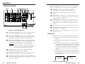
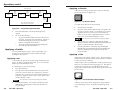
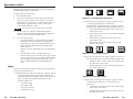
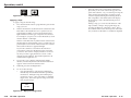
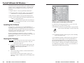
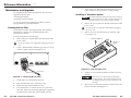
User’s Manual
ECP 1000
Event Control Panel
www.extron.com
Extron Electronics, USA
Extron Electronics, Europe
Extron Electronics, Asia
Extron Electronics, Japan
1230 South Lewis Street
Anaheim, CA 92805
USA
714.491.1500
Fax 714.491.1517
Beeldschermweg 6C
3821 AH Amersfoort
The Netherlands
+31.33.453.4040
Fax +31.33.453.4050
135 Joo Seng Road, #04-01
PM Industrial Building
Singapore 368363
+65.6383.4400
Fax +65.6383.4664
Daisan DMJ Building 6F
3-9-1 Kudan Minami
Chiyoda-ku, Tokyo 102-0074 Japan
+81.3.3511.7655
Fax +81.3.3511.7656
© 2002 Extron Electronics. All rights reserved.
68-518-01
Printed in the USA
Table of Contents
Chapter 1 • Introduction .......................................................... 1-1
Features ...................................................................................... 1-2
Chapter 2 • Installation ............................................................. 2-1
Rear Panel Features ............................................................. 2-2
Installation ............................................................................... 2-2
Chapter 3 • Operation ................................................................ 3-1
Top Panel Controls ................................................................. 3-2
Power-up .................................................................................... 3-3
Using the Menus ..................................................................... 3-4
Changing the backlight intensity .......................................... 3-4
Performing a system reset .................................................... 3-5
Programming the ECP 1000 .................................................. 3-5
Applying a Switch ................................................................. 3-6
Applying a cut ........................................................................ 3-6
Applying a dissolve ................................................................. 3-7
Applying a title ....................................................................... 3-7
Wipes ...................................................................................... 3-8
Applying a wipe ................................................................... 3-10
Chapter 4 • Control Software for Windows ............... 4-1
Installing the Software ...................................................... 4-2
Starting the Software ......................................................... 4-2
Appendix • Reference Information .................................. A-1
Maintenance and Upgrades ............................................ A-2
Cleaning the filter fan .......................................................... A-2
Installing a firmware update ............................................... A-3
Replacing keycap labels ........................................................ A-5
Specifications ......................................................................... A-5
Part Numbers .......................................................................... A-6
68-518-01 Rev. B
Printed in the USA
04 02
ECP 1000 • Table of Contents
i
Table of Contents, cont’d
ECP 1000 Event Control Panel
1
Chapter One
Introduction
Features
ii
ECP 1000 • Table of Contents
Introduction, cont’d
Introduction
The Extron ECP 1000 event control panel attaches to as many as
three Extron SGS 408 seamless switchers to provide complete
control of multiple screens in large staging applications. The
ECP 1000 allows you to create simultaneous or synchronous
wipes, dissolves, fades, and cuts on any combination of the
attached screens.
The ECP 1000 includes pre-programmed effects that are
available at the touch of a single button. In addition, the
SGS 408 Control Program for Windows allows you to select
effects for each screen so you can create your own preset series
of effects.
Features
Pre-programmed effects — The effect buttons initiate multiscreen effects. There are 40 user-programmable presets,
30 of which are pre-programmed at the factory. The
SGS 408 Control Program for Windows allows you to
overwrite all preset button settings.
Show sequencing — Using the SGS 408 Control Program for
Windows, you can create a series of effects that are
initiated sequentially at the touch of a single effect
selection button.
Button label software — Some buttons are labeled with a
pictorial example of their associated effects. You can
create labels for unlabeled buttons, or you can replace
existing labels to match any changes you have made to
button assignments.
Effect selection buttons — These buttons allow you to create
wipes, dissolves, and title effects.
2
Chapter Two
Installation
Screen selection buttons — These buttons allow you to choose
the screen or screens on which an effect will appear.
Rear Panel Features
Duration adjustment — This control allows you to specify the
length of time in which each effect occurs.
Installation
T-bar controller — This control allows you to manually control
the speed of a transition.
1-2
ECP 1000 Event Control Panel
ECP 1000 • Introduction
Installation, cont’d
Installation
Rear Panel Features
3
100-240V
TO SGS
2
5
Continue the procedure for installing the SGS 408.
6
Attach power cords and plug the SGS 408 seamless
switcher, ECP 1000 event control panel, input devices, and
output devices into a grounded AC source.
7
Select an input from the front panel buttons on the
SGS 408 switcher or RCP 1000 remote control unit.
8
The image should now appear. If not, ensure that all
devices are plugged in and receiving power. Check the
cabling and make adjustments as needed. Select a
different input to check for a display.
1
PROGRAM
50/60 Hz 0.5A
1
2
3
4
Figure 2-1 — ECP 1000 rear panel
1
AC power connector — One standard AC power connector
attaches the event control panel to any power source from
100VAC to 240VAC, operating at 50 or 60 Hz.
2
Cooling fan — One fan cools the ECP 1000 unit. The filter can
be removed and washed as needed. See page A-2 for
instructions.
3
RS-232/program connector — One 9-pin D female connector
allows you to communicate with Extron’s SGS 408 Control
Program.
Projectors
SGS 408
T
EFFECSITION
TRAN
INPUT
AM
W
PROGR
PREVIE
T RATE
IC
ITIONS
TAKE
TRANS
CUT
5
AM
W
PROGR
PREVIE
IC
ITIONS
TAKE
TRANS
CUT
SEAML
4
3
8
1
7
3
BLACK
TION
UNICA
COMM
RCP Tx
5
IEW4
PREV
6
E
FREEZ
5
IEW4
PREV
Rx
3
2
3
SGS 408
1
1
BLACK
BLACK
E
E
FREEZ
Preview
Monitor
TION
UNICA
COMM
RCP Tx
Rx
2
2
1
BLACK
E
HER
SWITC
5
3
2
8
7
6
E
FREEZ
Rx
FREEZ
IC
GRAPH
ESS
SEAML
EFFEC
1
4
RAM
PROG
3
3
2
1
BLACK
TION
UNICA
COMM
RCP Tx
T RATE
TS 2
7
6
4
4
RAM
PROG
3
8
7
6
5
IEW4
PREV
AM
W
PROGR
PREVIE
OUTPU
8
TS 2
EFFEC
1
5
4
4
RAM
PROG
3
408
SGS
HER
SWITC
GRAPH
ESS
T RATE
OUTPU
8
7
6
2
RS-232/SGS 408 connectors — Three 9-pin D female connectors
allow you to attach an ECP 1000 event control panel to up to
three SGS 408 seamless switchers. The connectors correspond to
the screen selection buttons on the ECP 1000’s top panel.
T
EFFECSITION
TRAN
INPUT
408
SGS
HER
SWITC
GRAPH
ESS
SEAML
OUTPU
TS 2
EFFEC
1
1
BLACK
E
FREEZ
4
SGS 408
T
EFFECSITION
TRAN
INPUT
408
SGS
ITIONS
TAKE
TRANS
CUT
8
7
6
FREEZ
Program
Monitor
Preview
Monitor
Program
Monitor
Program
Monitor
S
SITION
TRAN
TS
EFFEC
ECP 1000
8
7
6
5
RAM
0
100
8
4
PROG
7
3
Up to 50'
TION
TxRx
RCP
5
VIEW
PPRE
BLACK
E
N
OTE
REM
4
3
FREEZ
SCREE
COMM
L
PANE
TROL
CON
UNICA
6
2
1
Preview
Monitor
2
T
0
100
ADJUS
1
L
PANE
ECP
BLACK
E
TROL
FREEZ
T CON
EVEN
Installation
R
CENTE
T
SIZE
FILTER /BRIGH
COND
HORZ
T
S
VERT
BRIGH
SITION
TRAN
CONT
TS
EFFEC
8
7
6
5
RAM
0
100
8
4
PROG
7
3
TION
TxRx
RCP
TROL
CON
UNICA
6
2
5
1
VIEW
PPRE
BLACK
E
4
COMM
OTE
REM
L
PANE
Control Room
3
FREEZ
2
1
To install and set up the ECP 1000, follow these steps:
BLACK
E
FREEZ
R
CENTE
T
SIZE
FILTER /BRIGH
COND
HORZ
T
S
VERT
SITION
TRAN
BRIGH
CONT
TS
EFFEC
8
7
6
5
RAM
0
100
8
4
PROG
7
3
TION
TxRx
RCP
2-2
Mount the SGS 408 switcher(s) as described in the SGS 408
User’s Manual (Extron part number 68-520-01).
5
VIEW
PPRE
2
Set the ECP 1000 on a flat surface.
3
For each SGS 408 to which the ECP 1000 will be connected,
attach an ECP comm cable (provided with the SGS 408)
between an SGS connector on the ECP 1000 and the RS-232
connector on the SGS 408. Figure 2-2 shows a typical
application.
4
If desired, attach a host computer or other control device
to the RS-232/program connector.
ECP 1000 • Installation
E
COMM
L
PANE
TROL
CON
UNICA
6
2
1
BLACK
1
OTE
REM
4
3
FREEZ
2
RCP 1000
1
BLACK
E
FREEZ
R
CENTE
T
SIZE
FILTER /BRIGH
COND
HORZ
T
VERT
BRIGH
CONT
Figure 2-2 — SGS 408 and ECP 1000 application
ECP 1000 • Installation
2-3
Installation, cont’d
ECP 1000 Event Control Panel
3
Chapter Three
Operation
Top Panel Controls
Power-up
Using the Menus
Applying a Switch
2-4
ECP 1000 • Installation
Operation, cont’d
Operation
Top Panel Controls
1
2
3
4
5
6
7
8
CUT
DISSOLVE
TITLE
9
7
Dissolve button — Allows you to set up a dissolving switch.
See “Applying a dissolve” on page 3-7 for more information.
8
Title button — Allows you to set up a title switch. See
“Applying a title” on page 3-7 for more information.
9
Take button — Initiates the switch selected by the effect
buttons.
10
T-bar controller — Allows you to override the duration of an
effect. See step 4 in “Applying a title” on page 3-8 or step 5 in
“Applying a wipe” on page 3-10.
11
Adjustment knob — Allows you to make adjustments to the
menu selections (see “Using the Menus” on page 3-4) and to
change the duration of an effect (see “Applying a Switch” on
page 3-6.
12
LCD screen — Displays status information and menu screens.
13
Next button — Steps through LCD screens within a menu. See
“Using the Menus” on page 3-4.
14
Menu button — Steps through LCD menus. See “Using the
Menus” on page 3-4.
SCREEN
1
2
SOFT
EDGE
3
10
TAKE
ADJUST
MENU
11
NEXT
ECP 1000
EVENT CONTROL PANEL
14
13 12
Figure 3-1 — ECP 1000 top panel
1
2
3
One-screen effect buttons — Allow you to specify the effects for
one screen. All of the buttons are user-programmable.
Two-screen effect buttons — Allow you to specify the effects
for two screens. The buttons in the two right columns are preprogrammed. All of the buttons are user-programmable.
When the ECP 1000 is powered up, the following events occur:
Three-screen effect buttons — Allow you to specify the effects
for three screens. The buttons in the two right columns are preprogrammed. All of the buttons are user-programmable.
• The ECP 1000 detects the number of SGS 408 units that are
connected.
The names “one-screen”, “two-screen”, and “threescreen” are not absolutes. You can program a one-screen
effect into a three-screen effect button. The names are
used only to identify the particular set of buttons.
4
Power-up
Soft edge button — Allows you to select whether singledimension wipes will have hard or soft edges.
5
Screen selection buttons — Allow you to choose the screen on
which effects, cuts, dissolves, and titles will take place.
6
Cut button — Initiates an immediate seamless switch between
the program and preview images. See “Applying a cut” on page
3-6 for more information.
• All lights on the ECP 1000 front panel turn on and then off, in
sequence.
• The buttons that are programmed to work with the number of
connected SGS 408 units become backlit. For example, if
SGS 408 units are attached to SGS ports 1 and 3, all screen
effect buttons that are programmed to work with 1 or 2
screens become backlit, as do screen selection buttons 1
and 3.
• The LCD displays the name of the product, and then displays
the attached screens (based on the connected ports) and
the default effect duration (figure 3-2). This second screen
is the default screen.
SGS 1 . 3
1.0 SEC
EXTRON
ECP-1000
Figure 3-2 — Power-up screens
3-2
ECP 1000 • Operation
ECP 1000 • Operation
3-3
Operation, cont’d
In the display of attached screens, a dot represents a
screen that is not attached.
Performing a system reset
The ECP 1000 menus allow you to do the following:
A system reset returns all settings to their factory defaults. It
removes all user-programmed effects, and returns preprogrammed effect buttons to their original effects. It also
cancels the screen selection button settings.
• Change the backlight intensity (see below).
To perform a system reset, do the following:
• Perform a system reset (see page 3-5).
1.
Using the Menus
From the default screen, press the Menu button twice. The
System Reset menu appears (figure 3-4).
• Program the ECP 1000 (see page 3-5).
Changing the backlight intensity
The buttons on the top panel of the ECP 1000 are backlit to
make them easier to see in rooms with low-level lighting. You
can control the amount of light the buttons emit by doing the
following:
1.
From the default screen, press the Menu button. The Back
Light menu appears (figure 3-3).
Press
Menu
button
SGS 1 . 3
1.0 SEC
Press
Next
button
Press
Menu
button
three
times
BACK
LIGHT
Press
Menu
button
SGS 1 . 3
1.0 SEC
(System
reset
does
not
occur)
(System
reset
occurs)
SYSTEM
RESET
Press
Menu
button
Press
Next
button
PROGRAM
MODE
Press
Menu
button
Press Take button
TAKE TO
CONFIRM
Figure 3-4 — Performing a system reset
2.
Press the Next button. The Take to Confirm menu
appears.
3.
Do one of the following:
Press
Menu
button
Rotate
Adjust
knob
Figure 3-3 — Changing the backlight
2.
Press the Next button. The Intensity screen appears.
3.
Rotate the Adjust knob until the backlight is at the desired
intensity.
4.
Do one of the following:
•
To exit the LCD menu, press the Menu button three
times. The default screen appears.
•
To proceed to the System Reset menu, press the
Menu button once.
•
To return to the Back Light menu, press the Next
button once.
ECP 1000 • Operation
Press
Next
button
Press Menu button twice
INTENSITY
30%
3-4
BACK
LIGHT
Press
Menu
button
SYSTEM
RESET
Press
Next
button
INTENSITY
20%
Press
Menu
button
•
To confirm the system reset, press the Take button.
The system reset occurs, and the default screen
appears.
•
To cancel the system reset and exit the LCD menu,
press the Menu button twice. The default screen
appears.
•
To proceed to the Program Mode menu, press the
Menu button once.
Programming the ECP 1000
When the ECP 1000 is in program mode, it cannot
control effects on the SGS 408.
The SGS 408 Control Program allows you to program the
ECP 1000. Before the software can communicate with the
ECP 1000, the ECP 1000 must be in program mode. To enter
program mode, do the following:
1.
From the default screen, press the Menu button three
times. The Program Mode menu appears (figure 3-5 on
the next page).
ECP 1000 • Operation
3-5
Operation, cont’d
Applying a dissolve
Press Menu button
Press
Menu
button
SGS 1 . 3
1.0 SEC
BACK
LIGHT
Press
Menu
button
SYSTEM
RESET
Press
Menu
button
A dissolve causes the program image to fade out while the
preview image fades in (figure 3-6).
PROGRAM
MODE
Dissolve
Press
Next
button
Use the SGS 408 Control Program.
When finished, press Menu button.
Figure 3-6 — A dissolve effect
PROGRAM
*READY*
Figure 3-5 — Programming the ECP 1000
2.
Press the Next button. The Program Ready menu
appears.
3.
Do one of the following:
•
•
To program the ECP 1000, use the SGS 408 Control
Program. See chapter 4 for information. When you
are finished using the program, press the Menu
button. The default screen appears.
To exit the LCD menu without programming the
ECP 1000, press the Menu button.
Applying a Switch
You can switch displays using a variety of techniques. For a
description of each technique, see the instructions for the
technique in this section.
Applying a cut
A cut seamlessly replaces the program image with the preview
image. No effect is applied to the switch. As soon as the Take
button is pressed, the switch occurs.
To switch using a cut, do the following:
1.
Press the Cut button.
2.
Press the screen selection buttons that correspond to the
screens you want to switch. For example, if you want to
apply the cut to screen 2, press screen selection button 2. If
you want to apply the cut to screens 1 and 3, press screen
selection buttons 1 and 3.
You can select a screen selection only if it is backlit.
3.
3-6
Press the Take button. The seamless switch takes effect
immediately, and the preview image becomes the new
program image.
ECP 1000 • Operation
To switch using a dissolve, do the following:
1.
Press the Dissolve button.
2.
Press the screen selection buttons that correspond to the
screens you want to switch. For example, if you want to
apply the dissolve to screen 2, press screen selection
button 2. If you want to apply the dissolve to screens 1
and 3, press screen selection buttons 1 and 3.
You can select a screen selection only if it is backlit.
3.
If you want to use a duration other than the default
duration, turn the Adjust knob until the desired duration
appears on the LCD menu’s default screen.
4.
Press the Take button. The dissolving switch begins
immediately and is finished in the time specified by the
duration, and the preview image becomes the new
program image.
Applying a title
A title can have two effects: window or key. The actual effect is
determined by the ECP title setting on the SGS 408 (see chapter
3 of the SGS 408 User’s Manual).
A title window causes a predefined box in the program image to
dissolve to reveal the preview image (figure 3-7). The effect is
as if the preview image were located behind the program
image, and a window in the program image opens to show the
preview image.
Figure 3-7 — A title window effect example
A title key causes any portion of the preview image which is
over half intensity (.35V) to be displayed with the program
image.
ECP 1000 • Operation
3-7
Operation, cont’d
When the either title effect ends, the preview image disappears,
and the program image is again intact.
To apply a title, do the following:
1.
Press the Title button.
2.
Press the screen selection buttons that correspond to the
screens you want to switch. For example, if you want to
apply the title to screen 2, press screen selection button 2.
If you want to apply the title to screens 1 and 3, press
screen selection buttons 1 and 3.
You can select a screen selection only if it is backlit.
3.
4.
left to right
right to left
top to bottom
bottom to top
Figure 3-8 — Standard wipe transitions
• A curtain wipe causes the preview image to appear to unroll
over the program image in two directions
simultaneously. The preview image can wipe across the
program image with the following transitions (figure 3-9):
•
If you want to use a duration other than the default
duration, turn the Adjust knob until the desired duration
appears on the LCD menu’s default screen.
In from the left and right edges of the screen to the
center of the screen
•
Out from the center of the screen to the left and right
edges of the screen
Do one of the following.
•
In from the top and bottom of the screen to the
center of the screen
•
Out from the center of the screen to the top and
bottom of the screen
•
Press the Take button. During the time specified by
the duration, the selected portion of the program
image dissolves away to be replaced by the preview
image. The Take button remains lit, and the Title
button flashes.
When you want to end the title, press the Take button
again.
•
Move the T-bar control. The title appears and
remains until you move the T-bar to the opposite end
point of the t-bar slot. Or, you could stop moving the
T-bar and press the Take button, in which case the
title is completed during the remaining duration
time.
Wipes
Figure 3-9 — Curtain wipe effects
• A plus wipe causes the preview image to appear to unroll over
the program image in one of two transitions (figure 3-10):
•
Starting in all four corners of the screen and moving
in to the center of the screen
•
Starting in the center of the screen and moving out to
the corners of the screen
A wipe causes the preview image to replace the program image
in any one of many directions.
• A standard wipe causes the preview image to appear to unroll
over the program image horizontally or vertically. By
default, the wipe has hard edges. The preview image can
wipe across the program image with the following
transitions (figure 3-8):
3-8
•
From left to right
•
From right to left
•
From top to bottom
•
From bottom to top
ECP 1000 • Operation
Figure 3-10 — Plus wipe effects
• A square wipe causes the preview image to appear to unroll
over the program image in one of two transitions
(figure 3-11):
•
Starting at all four edges of the screen and moving in
to the center of the screen
•
Starting in the center of the screen and moving out to
the edges of the screen
ECP 1000 • Operation
3-9
Operation, cont’d
•
Figure 3-11 — Square wipe effects
Applying a wipe
To apply a wipe, do the following:
1.
Press the effect button that is programmed to perform the
wipe you want.
2.
If this is the first time any effect has been selected since the
ECP 1000 was first installed or since a system reset was
performed, the number of screen selection buttons that
light will be based on the type of wipe that was selected.
For example, if you press a two-screen effect button, screen
selection buttons 1 and 2 light.
Move the T-bar control. The wiping switch takes
place until you move the T-bar to the opposite end
point of the t-bar slot. Or, you could stop moving the
T-bar and press the Take button, in which case the
switch is completed during the remaining duration
time. Regardless of the method, the LCD displays
the percentage count as described in the previous
paragraph.
During a wipe, you can reverse the direction of the
wipe (in effect, “unwipe” the program image) by
reversing the direction of the T-bar control. This is
true until the T-bar reaches the end point of the T-bar
slot, in which case the effect is considered completed.
If this is not the first time any effect has been selected since
the ECP 1000 was first installed or since a system reset was
performed, the screen selection buttons that were selected
the last time an effect was applied will light.
If you want to deselect a screen that is lit and select a
screen that is not lit, press the button for the screen that
you want to turn off. For example, if buttons 1 and 2 are
lit, and you want to apply the effect to screens 1 and 3
instead, press the 2 button. The 2 button light turns off,
and the 3 button light turns on.
3.
If you want to use a duration other than the default
duration, turn the Adjust knob until the desired duration
appears on the LCD menu’s default screen.
4.
If desired, press the Soft Edge button.
5.
Do one of the following.
•
Press the Take button. The wiping switch begins
immediately and is finished in the time specified by
the duration. During the wipe, the LCD displays a
percentage count (1 – 100) as the effect is completed
(figure 3-12). The former preview image is now the
new program image.
28%
3.0 SEC
Figure 3-12 — Wipe percentage count
3-10
ECP 1000 • Operation
ECP 1000 • Operation
3-11
Operation, cont’d
ECP 1000 Event Control Panel
4
Chapter Four
Control Software for Windows
Installing the Software
Starting the Software
3-12
ECP 1000 • Operation
Control Software
forfor
Windows,
cont’d
Control
Software
Windows
The SGS 408 Control Program (Extron part number 29-049-01) ,
which is used to configure the ECP 1000, is compatible with
Windows 95/98 and Windows NT. It allows you to do the
following:
• Assign an effect to a user-programmable effect button.
• Overwrite the effect assigned to either a pre-programmed
effect button or a user-programmable effect button.
• Print new keycap labels for reprogrammed effect buttons.
• Create a series of effects that are initiated sequentially at the
touch of a single effect button.
The SGS 408 Control Program is the only method you
can use to program the ECP 1000. RS-232 commands
are not available.
Installing the Software
The program is contained on a set of 3.5-inch diskettes. To
install the program from the floppy disks to the hard drive, run
SETUP.EXE from the floppy disk and follow the instructions
that appear on the screen. The program occupies approximately
3 MB (megabytes) of hard-drive space.
By default, the Windows installation creates a C:\SGS408
directory, and it will place two icons (SGS 408 Control Pgm and
SGS 408 Help) into a group or folder named “Extron
Electronics”.
Starting the Software
Before starting the SGS 408 Control Program, you must
put the ECP 1000 into program mode. Follow the
instructions on page 3-5.
1.
To run the SGS 408 Control Program, double-click on the
SGS 408 Control Pgm icon (left) in the Extron
Electronics group or folder.
2.
Click on the comm port that is connected to the RS-232
port of the ECP 1000.
Figure 4-1 — SGS 408 Control Program window
example (when an ECP 1000 is connected)
For information about program features, you can access the
help program in any of the following ways:
• From the Extron Electronics program folder or group, doubleclick on the SGS 408 Help icon (shown at the left).
SGS 408
Help
• From within the SGS 408 Control Program, click on the Help
menu on the main screen.
• From within the SGS 408 Control Program, press the F1 key.
After you have made changes to the user-programmable or
pre-programmed effect buttons, you can print a page of new
labels for the effect buttons. From the File menu, choose Print
ECP keycap labels. The labels are printed to the default printer.
See “Replacing keycap labels” on page A-5 for information on
inserting the new labels into the keycaps.
The SGS 408 Control Program window appears (see
figure 4-1 example). It displays the current settings of the
ECP 1000.
4-2
ECP 1000 • Control Software for Windows
ECP 1000 • Control Software for Windows
4-3
Control Software for Windows, cont’d
ECP 1000 Event Control Panel
A
Appendix
Reference Information
Maintenance and Upgrades
Specifications
Part Numbers
4-4
ECP 1000 • Control Software for Windows
Reference Information,
cont’d
Reference
Information
7.
Maintenance and Upgrades
You can perform the following maintenance operations and
upgrades to the ECP 1000:
Installing a firmware update
• Cleaning the fan filter
To install a firmware update, you may need to replace IC
(integrated circuit) U9 or U11, or both. Replacing these
ICs may result in loss of presets and other settings.
• Installing a firmware update
You can also replace the existing button labels if you have
reprogrammed any of the effect buttons.
1.
Cleaning the fan filter
The fan filter should be cleaned periodically, The frequency
with which you need to clean the filter depends on the
operating environment.
Attach the power cable to the ECP 1000 and to the power
source. Make sure the ECP 1000 is working correctly.
Remove the power cable from the ECP 1000 and from the
power source.
Do not open the cover of the ECP 1000 without unplugging
the power cord.
2.
Remove 10 screws from the back, top, and front of the
cover (figure A-2).
To clean the fan filter, do the following:
1.
Lift Cover straight up.
Remove the power cable from the ECP 1000 and from the
power source.
Remove 10
screws
Do not open the fan cover without first unplugging the power
cord.
2.
N
REE
SC
Using a small flat-blade screwdriver, pry the fan cover off
of the rear panel of the ECP 1000 (figure A-1).
00
ST
JU
AD
0
L
P 1 ANE
EC ROL P
T
ON
TC
EN
EV
Fan
3
100-240V
50/60 Hz 0.5A
TO SGS
2
1
PROGRAM
Filter
Figure A-2 — Removing the cover
Filter Cover
Pry off Cover
3.
Make sure you are electrically grounded before
touching IC chips. Electrostatic discharge (EDS)
can damage IC chips, even if you cannot sense the
discharge.
Figure A-1 — Removing the fan filter
A-2
3.
Lift the filter out of the fan filter enclosure.
4.
Rinse the filter with water, and allow it to dry.
5.
Replace the filter in the fan filter enclosure.
6.
Press the fan filter cover back onto the rear panel of the
ECP 1000. Make sure the left and right edges snap behind
the shallow tabs on the sides of the fan filter enclosure.
ECP 1000 • Reference Information
Lift the cover from the ECP 1000 unit, and place it next to
the unit.
4.
Remove the 12 screws that attach the control board to the
bottom of the ECP 1000 (figure A-3).
ECP 1000 • Reference Information
A-3
Reference Information, cont’d
5.
socket, and gently press the IC into the socket.
Locate the ICs to be replaced (figure A-3). The update kit
will list the specific ICs.
8.
Reinstall the cover of the ECP 1000.
9.
Attach the power cord to the ECP 1000 and to the AC
power source. Make sure the ECP 1000 is working
correctly.
Replacing keycap labels
You can remove each effect button to reveal a legend plate
(figure A-4). Remove the cap and insert a button label to
identify the button’s new assignment. You can print labels from
the SGS 408 Control Program (see page 4-3).
Separate board and cover
without straining the
internal wire connectors.
SCREEN
ADJUST
Screwdriver
ECP 1000
EVENT CONTROL PANEL
Remove 11
screws
U11
U9
TE
XT
Align Notches
Figure A-3 — Locating and replacing ICs
6.
Remove the existing chip and set it aside.
To remove IC U9, use the PLCC (plastic leadless chip
carrier) IC puller to remove the old IC. Align the hooks
on the puller with the slots provided in opposite corners of
chip socket U9. Insert the hooks, squeeze gently, and pull
the IC straight out of the socket.
To remove IC U11, use a standard IC removal tool.
7.
Install the new chip.
To install IC U9, locate the angled corner of the new chip.
Orient the corner to match the angled corner of the socket,
and press the IC into place.
To install IC U11, locate a notch or a printed dot on top of
the IC. Align the notch or dot with the notch on the socket
or circuit board. Align the IC pins with the holes in the
A-4
Figure A-4 — Removing a keycap
ECP 1000 • Reference Information
Specifications
General
Power ............................................ 100VAC to 240VAC, 50/60 Hz, 60 watts,
internal, auto-switchable
Temperature/humidity .............. Storage -40° to +158°F (-40° to +70°C) /
10% to 90%, non-condensing
Operating +32° to +122°F (0° to +50°C) /
10% to 90%, non-condensing
Rack mount .................................. No
Enclosure type .............................. Metal
ECP 1000 • Reference Information
A-5
Reference Information, cont’d
Enclosure dimensions ................. 4.6" H x 13.1" W x 7.0" D
11.7 cm H x 33.3 cm W x 17.8 cm D
(T-bar control adds up to 1.8” ((4.6 cm)) to
height.)
Product weight ............................. 4.4 lbs (2.0 kg)
Shipping weight ........................... 10 lbs (4.5 kg)
Vibration ....................................... ISTA/NSTA 1A in carton (International
Safe Transit Association)
Listings .......................................... UL, CUL
Compliances ................................. CE, FCC Class A
MTBF ............................................. 30,000 hours
Warranty ....................................... 3 years parts and labor
Specifications are subject to change without notice.
(7.31-110701-D1)
Part Numbers
Extron Part
ECP 1000
SGS 408
RCP 1000
ECP comm cable – 25’ (7.6 m)
ECP comm cable – 50’ (15.2 m)
RCP comm cable – 25’ (7.6 m)
RCP comm cable – 50’ (15.2 m)
RCP comm cable – 100’ (30.5 m)
RCP comm cable – 300’ (91.4 m)
SGS 408 Control Program
ECP 1000 User’s Manual
SGS 408 User’s Manual
RCP 1000 User’s Manual
A-6
ECP 1000 • Reference Information
Part Number
60-344-01
60-341-01
60-343-01
26-434-06
26-434-08
26-519-01
26-519-02
26-519-03
26-519-04
29-049-01
68-518-01
68-520-01
68-519-01
Precautions
Safety Instructions • English
This symbol is intended to alert the user of important
operating and maintenance (servicing) instructions
in the literature provided with the equipment.
This symbol is intended to alert the user of the
presence of uninsulated dangerous voltage within
the product's enclosure that may present a risk of
electric shock.
Caution
Read Instructions • Read and understand all safety and operating
instructions before using the equipment.
Retain Instructions • The safety instructions should be kept for future
reference.
Follow Warnings • Follow all warnings and instructions marked on the
equipment or in the user information.
Avoid Attachments • Do not use tools or attachments that are not
recommended by the equipment manufacturer because they may be
hazardous.
Consignes de Sécurité • Français
Ce symbole sert à avertir l’utilisateur que la
documentation fournie avec le matériel contient des
instructions importantes concernant l’exploitation
et la maintenance (réparation).
Ce symbole sert à avertir l’utilisateur de la présence
dans le boîtier de l’appareil de tensions dangereuses
non isolées posant des risques d’électrocution.
Attention
Lire les instructions• Prendre connaissance de toutes les consignes de
sécurité et d’exploitation avant d’utiliser le matériel.
Conserver les instructions• Ranger les consignes de sécurité afin de
pouvoir les consulter à l’avenir.
Respecter les avertissements • Observer tous les avertissements et
consignes marqués sur le matériel ou présentés dans la documentation
utilisateur.
Eviter les pièces de fixation • Ne pas utiliser de pièces de fixation ni
d’outils non recommandés par le fabricant du matériel car cela
risquerait de poser certains dangers.
Sicherheitsanleitungen • Deutsch
Dieses Symbol soll dem Benutzer in der im
Lieferumfang enthaltenen Dokumentation
besonders wichtige Hinweise zur Bedienung und
Wartung (Instandhaltung) geben.
Dieses Symbol soll den Benutzer darauf aufmerksam
machen, daß im Inneren des Gehäuses dieses
Produktes gefährliche Spannungen, die nicht isoliert
sind und die einen elektrischen Schock verursachen
können, herrschen.
Achtung
Lesen der Anleitungen • Bevor Sie das Gerät zum ersten Mal verwenden,
sollten Sie alle Sicherheits-und Bedienungsanleitungen genau
durchlesen und verstehen.
Aufbewahren der Anleitungen • Die Hinweise zur elektrischen Sicherheit
des Produktes sollten Sie aufbewahren, damit Sie im Bedarfsfall darauf
zurückgreifen können.
Befolgen der Warnhinweise • Befolgen Sie alle Warnhinweise und
Anleitungen auf dem Gerät oder in der Benutzerdokumentation.
Keine Zusatzgeräte • Verwenden Sie keine Werkzeuge oder Zusatzgeräte,
die nicht ausdrücklich vom Hersteller empfohlen wurden, da diese eine
Gefahrenquelle darstellen können.
Instrucciones de seguridad • Español
Este símbolo se utiliza para advertir al usuario sobre
instrucciones importantes de operación y
mantenimiento (o cambio de partes) que se desean
destacar en el contenido de la documentación
suministrada con los equipos.
Este símbolo se utiliza para advertir al usuario sobre
la presencia de elementos con voltaje peligroso sin
protección aislante, que puedan encontrarse dentro
de la caja o alojamiento del producto, y que puedan
representar riesgo de electrocución.
Precaucion
Leer las instrucciones • Leer y analizar todas las instrucciones de
operación y seguridad, antes de usar el equipo.
Conservar las instrucciones • Conservar las instrucciones de seguridad
para futura consulta.
Obedecer las advertencias • Todas las advertencias e instrucciones
marcadas en el equipo o en la documentación del usuario, deben ser
obedecidas.
Evitar el uso de accesorios • No usar herramientas o accesorios que no
sean especificamente recomendados por el fabricante, ya que podrian
implicar riesgos.
FCC Class A Notice
Warning
Power sources • This equipment should be operated only from the power source
indicated on the product. This equipment is intended to be used with a main
power system with a grounded (neutral) conductor. The third (grounding) pin is
a safety feature, do not attempt to bypass or disable it.
Power disconnection • To remove power from the equipment safely, remove all
power cords from the rear of the equipment, or the desktop power module (if
detachable), or from the power source receptacle (wall plug).
Power cord protection • Power cords should be routed so that they are not likely to
be stepped on or pinched by items placed upon or against them.
Servicing • Refer all servicing to qualified service personnel. There are no userserviceable parts inside. To prevent the risk of shock, do not attempt to service
this equipment yourself because opening or removing covers may expose you to
dangerous voltage or other hazards.
Slots and openings • If the equipment has slots or holes in the enclosure, these are
provided to prevent overheating of sensitive components inside. These openings
must never be blocked by other objects.
Lithium battery • There is a danger of explosion if battery is incorrectly replaced.
Replace it only with the same or equivalent type recommended by the
manufacturer. Dispose of used batteries according to the manufacturer's
instructions.
Note: This equipment has been tested and found to comply with the limits for a
Class A digital device, pursuant to part 15 of the FCC Rules. These limits are
designed to provide reasonable protection against harmful interference when the
equipment is operated in a commercial environment. This equipment generates,
uses and can radiate radio frequency energy and, if not installed and used in
accordance with the instruction manual, may cause harmful interference to radio
communications. Operation of this equipment in a residential area is likely to
cause harmful interference, in which case the user will be required to correct the
interference at his own expense.
Note: This unit was tested with shielded cables on the peripheral devices.
Shielded cables must be used with the unit to ensure compliance.
Avertissement
Alimentations• Ne faire fonctionner ce matériel qu’avec la source d’alimentation
indiquée sur l’appareil. Ce matériel doit être utilisé avec une alimentation
principale comportant un fil de terre (neutre). Le troisième contact (de mise à la
terre) constitue un dispositif de sécurité : n’essayez pas de la contourner ni de la
désactiver.
Déconnexion de l’alimentation• Pour mettre le matériel hors tension sans danger,
déconnectez tous les cordons d’alimentation de l’arrière de l’appareil ou du
module d’alimentation de bureau (s’il est amovible) ou encore de la prise secteur.
Protection du cordon d’alimentation • Acheminer les cordons d’alimentation de
manière à ce que personne ne risque de marcher dessus et à ce qu’ils ne soient
pas écrasés ou pincés par des objets.
Réparation-maintenance • Faire exécuter toutes les interventions de réparationmaintenance par un technicien qualifié. Aucun des éléments internes ne peut être
réparé par l’utilisateur. Afin d’éviter tout danger d’électrocution, l’utilisateur ne
doit pas essayer de procéder lui-même à ces opérations car l’ouverture ou le
retrait des couvercles risquent de l’exposer à de hautes tensions et autres dangers.
Fentes et orifices • Si le boîtier de l’appareil comporte des fentes ou des orifices,
ceux-ci servent à empêcher les composants internes sensibles de surchauffer. Ces
ouvertures ne doivent jamais être bloquées par des objets.
Lithium Batterie • Il a danger d'explosion s'll y a remplacment incorrect de la
batterie. Remplacer uniquement avec une batterie du meme type ou d'un ype
equivalent recommande par le constructeur. Mettre au reut les batteries usagees
conformement aux instructions du fabricant.
Vorsicht
Stromquellen • Dieses Gerät sollte nur über die auf dem Produkt angegebene
Stromquelle betrieben werden. Dieses Gerät wurde für eine Verwendung mit
einer Hauptstromleitung mit einem geerdeten (neutralen) Leiter konzipiert. Der
dritte Kontakt ist für einen Erdanschluß, und stellt eine Sicherheitsfunktion dar.
Diese sollte nicht umgangen oder außer Betrieb gesetzt werden.
Stromunterbrechung • Um das Gerät auf sichere Weise vom Netz zu trennen,
sollten Sie alle Netzkabel aus der Rückseite des Gerätes, aus der externen
Stomversorgung (falls dies möglich ist) oder aus der Wandsteckdose ziehen.
Schutz des Netzkabels • Netzkabel sollten stets so verlegt werden, daß sie nicht
im Weg liegen und niemand darauf treten kann oder Objekte darauf- oder
unmittelbar dagegengestellt werden können.
Wartung • Alle Wartungsmaßnahmen sollten nur von qualifiziertem
Servicepersonal durchgeführt werden. Die internen Komponenten des Gerätes
sind wartungsfrei. Zur Vermeidung eines elektrischen Schocks versuchen Sie in
keinem Fall, dieses Gerät selbst öffnen, da beim Entfernen der Abdeckungen die
Gefahr eines elektrischen Schlags und/oder andere Gefahren bestehen.
Schlitze und Öffnungen • Wenn das Gerät Schlitze oder Löcher im Gehäuse
aufweist, dienen diese zur Vermeidung einer Überhitzung der empfindlichen
Teile im Inneren. Diese Öffnungen dürfen niemals von anderen Objekten
blockiert werden.
Litium-Batterie • Explosionsgefahr, falls die Batterie nicht richtig ersetzt wird.
Ersetzen Sie verbrauchte Batterien nur durch den gleichen oder einen
vergleichbaren Batterietyp, der auch vom Hersteller empfohlen wird. Entsorgen
Sie verbrauchte Batterien bitte gemäß den Herstelleranweisungen.
Advertencia
Alimentación eléctrica • Este equipo debe conectarse únicamente a la fuente/tipo
de alimentación eléctrica indicada en el mismo. La alimentación eléctrica de este
equipo debe provenir de un sistema de distribución general con conductor
neutro a tierra. La tercera pata (puesta a tierra) es una medida de seguridad, no
puentearia ni eliminaria.
Desconexión de alimentación eléctrica • Para desconectar con seguridad la
acometida de alimentación eléctrica al equipo, desenchufar todos los cables de
alimentación en el panel trasero del equipo, o desenchufar el módulo de
alimentación (si fuera independiente), o desenchufar el cable del receptáculo de
la pared.
Protección del cables de alimentación • Los cables de alimentación eléctrica se
deben instalar en lugares donde no sean pisados ni apretados por objetos que se
puedan apoyar sobre ellos.
Reparaciones/mantenimiento • Solicitar siempre los servicios técnicos de personal
calificado. En el interior no hay partes a las que el usuario deba acceder. Para
evitar riesgo de electrocución, no intentar personalmente la reparación/
mantenimiento de este equipo, ya que al abrir o extraer las tapas puede quedar
expuesto a voltajes peligrosos u otros riesgos.
Ranuras y aberturas • Si el equipo posee ranuras o orificios en su caja/alojamiento,
es para evitar el sobrecalientamiento de componentes internos sensibles. Estas
aberturas nunca se deben obstruir con otros objetos.
Batería de litio • Existe riesgo de explosión si esta batería se coloca en la posición
incorrecta. Cambiar esta batería únicamente con el mismo tipo (o su equivalente)
recomendado por el fabricante. Desachar las baterías usadas siguiendo las
instrucciones del fabricante.
Extron’s Warranty
Extron Electronics warrants this product against defects in materials and
workmanship for a period of three years from the date of purchase. In the event of
malfunction during the warranty period attributable directly to faulty
workmanship and/or materials, Extron Electronics will, at its option, repair or
replace said products or components, to whatever extent it shall deem necessary to
restore said product to proper operating condition, provided that it is returned
within the warranty period, with proof of purchase and description of malfunction
to:
USA, Canada, South America,
Europe, Africa, and the Middle East:
and Central America:
Extron Electronics, Europe
Extron Electronics
Beeldschermweg 6C
1230 South Lewis Street
3821 AH Amersfoort
Anaheim, CA 92805, USA
The Netherlands
Asia:
Extron Electronics, Asia
135 Joo Seng Road, #04-01
PM Industrial Bldg.
Singapore 368363
Japan:
Extron Electronics, Japan
Daisan DMJ Bldg. 6F,
3-9-1 Kudan Minami
Chiyoda-ku, Tokyo 102-0074
Japan
This Limited Warranty does not apply if the fault has been caused by misuse,
improper handling care, electrical or mechanical abuse, abnormal operating
conditions or non-Extron authorized modification to the product.
If it has been determined that the product is defective, please call Extron and ask for
an Applications Engineer at (714) 491-1500 (USA), 31.33.453.4040 (Europe), or
65.6383.4400 (Asia) to receive an RA# (Return Authorization number). This will
begin the repair process as quickly as possible.
Units must be returned insured, with shipping charges prepaid. If not insured,
you assume the risk of loss or damage during shipment. Returned units must
include the serial number and a description of the problem, as well as the name of
the person to contact in case there are any questions.
Extron Electronics makes no further warranties either expressed or implied with
respect to the product and its quality, performance, merchantability, or fitness for
any particular use. In no event will Extron Electronics be liable for direct, indirect,
or consequential damages resulting from any defect in this product even if Extron
Electronics has been advised of such damage.
Please note that laws vary from state to state and country to country, and that
some provisions of this warranty may not apply to you.