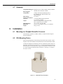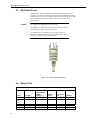
1
WXT520
Weather
Transmitter
User Manual
Issued 23.1.13
Copyright © 2006-2013 Campbell Scientific Inc.
Printed under licence by Campbell Scientific Ltd.
CSL 837
Guarantee
This equipment is guaranteed against defects in materials and workmanship.
This guarantee applies for twelve months from date of delivery. We will
repair or replace products which prove to be defective during the guarantee
period provided they are returned to us prepaid. The guarantee will not apply
to:
•
Equipment which has been modified or altered in any way without the
written permission of Campbell Scientific
•
Batteries
•
Any product which has been subjected to misuse, neglect, acts of God or
damage in transit.
Campbell Scientific will return guaranteed equipment by surface carrier
prepaid. Campbell Scientific will not reimburse the claimant for costs incurred
in removing and/or reinstalling equipment. This guarantee and the Company’s
obligation thereunder is in lieu of all other guarantees, expressed or implied,
including those of suitability and fitness for a particular purpose. Campbell
Scientific is not liable for consequential damage.
Please inform us before returning equipment and obtain a Repair Reference
Number whether the repair is under guarantee or not. Please state the faults as
clearly as possible, and if the product is out of the guarantee period it should
be accompanied by a purchase order. Quotations for repairs can be given on
request. It is the policy of Campbell Scientific to protect the health of its
employees and provide a safe working environment, in support of this policy a
“Declaration of Hazardous Material and Decontamination” form will be
issued for completion.
When returning equipment, the Repair Reference Number must be clearly
marked on the outside of the package. Complete the “Declaration of
Hazardous Material and Decontamination” form and ensure a completed copy
is returned with your goods. Please note your Repair may not be processed if
you do not include a copy of this form and Campbell Scientific Ltd reserves
the right to return goods at the customers’ expense.
Note that goods sent air freight are subject to Customs clearance fees which
Campbell Scientific will charge to customers. In many cases, these charges are
greater than the cost of the repair.
Campbell Scientific Ltd,
Campbell Park, 80 Hathern Road,
Shepshed, Loughborough, LE12 9GX, UK
Tel: +44 (0) 1509 601141
Fax: +44 (0) 1509 601091
Email: [email protected]
www.campbellsci.co.uk
PLEASE READ FIRST
About this manual
Please note that this manual was originally produced by Campbell Scientific Inc. primarily for the
North American market. Some spellings, weights and measures may reflect this origin.
Some useful conversion factors:
Area: 1 in2 (square inch) = 645 mm2
Length:
1 in. (inch) = 25.4 mm
1 ft (foot) = 304.8 mm
1 yard = 0.914 m
1 mile = 1.609 km
Mass:
1 oz. (ounce) = 28.35 g
1 lb (pound weight) = 0.454 kg
Pressure:
1 psi (lb/in2) = 68.95 mb
Volume:
1 UK pint = 568.3 ml
1 UK gallon = 4.546 litres
1 US gallon = 3.785 litres
In addition, while most of the information in the manual is correct for all countries, certain information
is specific to the North American market and so may not be applicable to European users.
Differences include the U.S standard external power supply details where some information (for
example the AC transformer input voltage) will not be applicable for British/European use. Please
note, however, that when a power supply adapter is ordered it will be suitable for use in your country.
Reference to some radio transmitters, digital cell phones and aerials may also not be applicable
according to your locality.
Some brackets, shields and enclosure options, including wiring, are not sold as standard items in the
European market; in some cases alternatives are offered. Details of the alternatives will be covered in
separate manuals.
Part numbers prefixed with a “#” symbol are special order parts for use with non-EU variants or for
special installations. Please quote the full part number with the # when ordering.
Recycling information
At the end of this product’s life it should not be put in commercial or domestic refuse
but sent for recycling. Any batteries contained within the product or used during the
products life should be removed from the product and also be sent to an appropriate
recycling facility.
Campbell Scientific Ltd can advise on the recycling of the equipment and in some cases
arrange collection and the correct disposal of it, although charges may apply for some
items or territories.
For further advice or support, please contact Campbell Scientific Ltd, or your local agent.
Campbell Scientific Ltd, Campbell Park, 80 Hathern Road, Shepshed, Loughborough, LE12 9GX, UK
Tel: +44 (0) 1509 601141 Fax: +44 (0) 1509 601091
Email: [email protected]
www.campbellsci.co.uk
Contents
PDF viewers: These page numbers refer to the printed version of this document. Use the
PDF reader bookmarks tab for links to specific sections.
1. Introduction ................................................................. 1
2. Cautionary Statements............................................... 1
3. Initial Inspection ......................................................... 1
4. Overview ...................................................................... 1
4.1
4.2
4.3
Wind Speed and Direction ..................................................................... 1
Precipitation ........................................................................................... 1
Barometric Pressure, Temperature, and Relative Humidity ................. 2
5. Specifications ............................................................. 2
5.1
5.2
5.3
5.4
5.5
5.6
5.7
Wind Speed ............................................................................................ 2
Wind Direction ....................................................................................... 2
Precipitation ........................................................................................... 2
Barometric Pressure ............................................................................... 2
Air Temperature ..................................................................................... 2
Relative Humidity .................................................................................. 2
Assembly ................................................................................................ 3
6. Installation ................................................................... 3
6.1
6.2
6.3
6.4
6.5
6.6
Mounting to a Campbell Scientific Crossarm ....................................... 3
IP66 Mounting Device ........................................................................... 3
Bird Spike Kit ........................................................................................ 4
Wiring Table .......................................................................................... 4
Commands .............................................................................................. 5
Programming .......................................................................................... 5
6.6.1 CRBasic .......................................................................................... 5
6.6.1.1 Example CR1000 Program .................................................. 6
6.6.1.2 Example CR200(X) Program .............................................. 7
6.6.2 Edlog Programming ........................................................................ 8
6.6.2.1 CR10X Program .................................................................. 8
Appendix
A. Configuring the WXT520 ........................................ A-1
i
Figures
6-1.
6-2.
A-1.
A-2.
A-3.
A-4.
008290 WXT520 IP66 Mount ...............................................................3
Optional Bird Spike Device ...................................................................4
Connection Setup screen ................................................................... A-1
Device Settings screen ...................................................................... A-2
Sensor Settings screen ....................................................................... A-3
Message Settings screen.................................................................... A-3
6-1.
6-2.
Connections to Campbell Scientific Dataloggers ..................................4
SDI-12 Commands .................................................................................5
Tables
ii
WXT520 Weather Transmitter
1.
Introduction
The WXT520 Weather Transmitter, manufactured by Vaisala, measures wind
speed and direction, precipitation, barometric pressure, temperature, and relative
humidity—all in a single device that has no moving parts. The WXT520’s SDI12 signal can be measured by any of our SDI-12 equipped dataloggers. The
WXT520 is about the size of our larger Gill radiation shield, making it ideal for
use with our CR200(X)-series dataloggers in applications requiring quick, shortterm deployment. However, the WXT520 is not intended for weather stations that
require research-grade performance.
Before installing the sensor, please study
•
•
2.
Cautionary Statements
•
3.
Although the WXT20 is rugged, it should be handled as a precision scientific
instrument.
Initial Inspection
•
4.
Section 2, Cautionary Statements
Section 3, Initial Inspection
Upon receipt of the WXT20, inspect the packaging and contents for damage.
File damage claims with the shipping company.
Overview
4.1
Wind Speed and Direction
The WXT520's wind sensor consists of three equally spaced transducers that
produce ultrasonic signals. Wind speed and direction are determined by
measuring the time it takes for the ultrasonic signal of one transducer to travel to
the other transducers. Wind direction is not calculated when the wind speed drops
below 0.05 m/s. In this case, the last calculated direction output remains until
wind speed increases. The computed wind speeds are independent of altitude,
temperature, and humidity. The WXT520 is preconfigured to provide the
minimum, average, and maximum values for both wind speed and direction.
Default wind speed units are m/s.
4.2
Precipitation
The WXT520 uses the RAINCAP® Sensor to measure accumulated rainfall, rain
intensity, and rain duration. Precipitation is measured one raindrop at a time.
Whenever a raindrop hits the precipitation sensor, an electrical signal is produced
that is proportional to the volume of the drop.
The sensor is also capable of distinguishing hail stones from raindrops. The
measured rain and hail parameters are cumulative amounts of rain or hail, rain or
hail intensity, and the duration of a shower.
1
WXT520 Weather Transmitter
4.3
Barometric Pressure, Temperature, and Relative Humidity
The WXT520 has a PTU module that contains a capacitive silicon BAROCAP®
sensor for barometric pressure measurements, a capacitive ceramic
THERMOCAP® sensor for air temperature measurements, and a capacitive thin
film polymer HUMICAP® sensor for relative humidity measurements. The PTU
is housed in a naturally aspirated radiation shield that protects the PTU and
reflects solar radiation. Default units are °Celsius for temperature and hPa for
barometric pressure.
5.
Specifications
5.1
Wind Speed
Measurement Range:
Accuracy:
Response Time:
5.2
Wind Direction
Measurement Range:
Accuracy:
Output Resolution:
5.3
0 to 60 m s-1
±3% at 10 m/s
0.25 s
0° to 360°
±3°
1°
Precipitation
Rainfall:
cumulative accumulation after latest automatic or
manual reset.
Accuracy:
5% (Due to the nature of the phenomenon, deviations
caused by spatial variations may exist in precipitation
readings, especially in short time scale. The accuracy
specification does not include possible wind induced
error.)
Collecting Area:
60 cm2
Output Resolution:
0.01 mm (0.001 in)
Rain Duration:
counting each ten second increment when droplet
detected.
Rain Intensity:
one minute running average in ten second steps.
Rainfall Intensity Range: 0 to 200 mm hr-1 (broader range possible with reduced
accuracy)
5.4
Barometric Pressure
Measurement Range:
Accuracy:
Output Resolution:
5.5
Air Temperature
Measurement Range:
Accuracy:
Output Resolution:
5.6
-52° to +60°C
±0.3°C @ +20°C
0.1°C
Relative Humidity
Measurement Range:
Accuracy:
Output Resolution:
2
600 to 1100 hPa (mbar)
±0.5 hPa @ 0° to 30°C; ±1 hPa @ -52° to +60°C
0.1 hPa
0 to 100% RH
±3% RH @ 0 to 90% RH; ±5% RH @ 90 to 100% RH
0.1% RH
User Manual
5.7
Assembly
Compatible Dataloggers: CR200(X)-series, CR800, CR850, CR1000, CR3000,
CR5000, CR510, CR10(X), CR23X
Electromagnetic
Compatibility:
Complies with EMC standard EN61326-1;
IEC standards: IEC 60945/61000-4-4, IEC
60945/61000-4-2
Input Voltage:
5 to 30 Vdc
Typical Current Drain
@ 12 Vdc:
3 mA with default measuring intervals;
0.1 mA (SDI-12 standby)
Output:
SDI-12 as configured by Campbell Scientific;
RS-232 and RS-485 also available
Operating Range:
-52° to +60°C; 0 to 100% RH
Dimensions:
24.0 cm (9.4 in) height, 12.0 cm (4.7 in) diameter
Weight:
650 g (1.43 lb)
6.
Installation
6.1
Mounting to a Campbell Scientific Crossarm
The WXT520 is mounted to a CM202, CM204, or CM206 crossarm using the
010779 mounting kit.
6.2
IP66 Mounting Device
The 010779 mounting kit provides better protection from water intrusion. When
using the 010779, the WXT520’s IP classification is increased from IP65 to IP66.
To attach the 008290 to the WXT520, place the L-shaped tabs into the notches on
the bottom of the WXT520 (see Figure 6-1). Turn the WXT520 until the mount is
locked into place. Once the 010779 is in place, the WXT520 is mounted to a mast
or crossarm using the method described in Section 6.1, Mounting to a Campbell
Scientific Crossarm.
Figure 6-1. 008290 WXT520 IP66 Mount
3
WXT520 Weather Transmitter
6.3
Bird Spike Device
The Bird Spike Device is fastened on top of the WXT520 using the set screw
provided (see Figure 6-2). This device is used to discourage birds from roosting
on the WXT520. It consists of a metallic band with spikes pointing upward. The
spike’s shape and location ensure minimal interference of wind and rain
measurements.
NOTES:
(1) The spikes are designed not to hurt the birds.
(2) While the use of this device does discourage interference from
birds, absolute protection cannot be guaranteed.
(3) When this device is attached, snow may be more prone to
accumulate on the head of the WXT520. In addition, the snow may
melt away more slowly during periods of thaw.
Figure 6-2. Optional Bird Spike Device
6.4
Wiring Table
Table 6-1. Connections to Campbell Scientific Dataloggers
Colour
Brown
Clear
(silver)
or Red
Blue
White
Green
4
Description
Power
Power ground
CR1000, CR800,
CR850, CR3000,
CR5000,
CR9000(X)
12 V
G
CR10(X),
CR510
12 V
G
21X, CR23X,
CR7
+12
G
CR200(X)
SW Battery
G
SDI-12 Signal
SDI-12 Signal
data ground
C1
C1
G
C2
C2
G
C2
C2
G
C1
C1
G
User Manual
Yellow
Pink
Optional heater
power (see note)
Optional heater
ground (see note)
Grey
NOTE
6.5
12V
12V
+12
SW Battery
G
G
G
G
Not used
Not used
Not used
Not used
Unless special ordered, the heater will not be operational for
WXT520s purchased from Campbell Scientific. Although the heater
is not operational, the WXT520 will have a pink and yellow wire.
Do not connect the pink and yellow wire unless the heater is
operational.
Commands
Campbell Scientific uses the SDI-12 protocol to communicate with the WXT520.
Both "aM!" and "aR!" commands are supported (where "a" is the sensor address).
The preferred command is "aR!", since the communication is done in fewer steps.
The WXT520 is configured to run continuously so the output is identical.
Table 6-2 contains the outputs as configured by Campbell Scientific. All outputs
are in SI units.
Table 6-2. SDI-12 Commands
6.6
SDI-12
Command
Command
Function
aR! or aM!
Composite
Message
Wind Direction Average, Wind Speed Average,
Air Temperature, Relative Humidity,
Barometric Pressure, Rainfall Amount, Hail
Amount
aR1! or
aM1!
Wind Message
Wind Direction Minimum, Wind Direction
Average, Wind Direction Maximum, Wind
Speed Minimum, Wind Speed Average, Wind
Speed Maximum
aR2! or
aM2!
PTU Message
Air Temperature, Relative Humidity,
Barometric Pressure
aR3! or
aM3!
Precipitation
Message
Rainfall Amount, rainfall Duration, Rainfall
Intensity, Hail Amount, Hail Duration, Hail
Intensity
aR5! or
aM5!
Self Diagnostic
Message
Supply Voltage, Internal Reference Voltage
Values Returned
Programming
6.6.1 CRBasic
Dataloggers that use CRBasic include our CR200(X)-series, CR800, CR850,
CR1000, CR3000, and CR5000. These dataloggers use the SDI12Recorder()
instruction to read the WXT520.
The SDI12Recorder() instruction has the following form:
SDI12Recorder(Destination, Output String, Multiplier, Offset)
5
WXT520 Weather Transmitter
6.6.1.1 Example CR1000 Program
Although the following program is for the CR1000, the CR800, CR850, CR3000,
and CR5000 are programmed similarly. This program uses the “aR!” command.
'CR1000 Series Datalogger
'Declarations
Public PTemp, batt_volt
Public WXT520(7)
Alias
Alias
Alias
Alias
Alias
Alias
Alias
WXT520(1)=WindDir
WXT520(2)=WindSpd
WXT520(3)=AirTemp
WXT520(4)=RelHumidity
WXT520(5)=AirPressure
WXT520(6)=Ramount
WXT520(7)=Hamount
Units
Units
Units
Units
Units
Units
Units
WindDir = Degrees
WindSpd = m/s
AirTemp = Celsius
RelHumidity = %
AirPressure = hPa
Ramount = mm
Hamount = hits/cm2
'Define Data Tables
DataTable (Test,1,-1)
DataInterval (0,60,Min,10)
WindVector (1,WindSpd,WindDir,FP2,False,900,0,0)
FieldNames("Ws_Mean,Wd_MeanUnitVector,Wd_StdDev")
Average (1,AirTemp,FP2,False)
Sample (1,RelHumidity,FP2)
Sample (1,AirPressure,IEEE4)
Totalize (1,Ramount,FP2,False)
Totalize (1,Hamount,FP2,False)
EndTable
'Main Program
BeginProg
'Running a 5 second scan to coincide with 5 second
'update interval of the WXT520
Scan (5,Sec,0,0)
PanelTemp (PTemp,250)
Battery (batt_volt)
'WXT520 connected to SDI12 port 1
SDI12Recorder (WXT520(1),1,0,"R!",1.0,0)
CallTable Test
NextScan
EndProg
6
User Manual
6.6.1.2 Example CR200(X) Program
'CR200/CR200X Series
'Declare Variables and Units
Public BattV
Public SDI12(7)
Alias
Alias
Alias
Alias
Alias
Alias
Alias
SDI12(1)=WindDir
SDI12(2)=WindSpd
SDI12(3)=AirTemp
SDI12(4)=RelHumidity
SDI12(5)=AirPressure
SDI12(6)=Ramount
SDI12(7)=Hamount
Units
Units
Units
Units
Units
Units
Units
Units
BattV=Volts
WindDir=Degrees
WindSpd=m/s
AirTemp=Celsius
RelHumidity=%
AirPressure=hPa
Ramount=mm
Hamount=hits/cm2
'Define Data Tables
DataTable(Hourly,True,-1)
DataInterval(0,60,Min)
WindVector (WindSpd,WindDir,False,0,0)
FieldNames("WindSpd_S_WVT,WindDir_D1_WVT,WindDir_SD1_WVT")
Average(1,AirTemp,False)
Sample(1,RelHumidity)
Sample(1,AirPressure)
Totalize(1,Ramount,False)
Totalize(1,Hamount,False)
EndTable
DataTable(Daily,True,-1)
DataInterval(0,1440,Min)
Minimum(1,BattV,False,False)
EndTable
'Main Program
BeginProg
SWBatt(1)
'Main Scan
Scan(10,Sec)
'Default Datalogger Battery Voltage measurement
Battery(BattV)
'WXT520
SDI12Recorder(SDI12(),"0R!",1,0)
'Call Data Tables and Store Data
CallTable(Hourly)
CallTable(Daily)
NextScan
EndProg
7
WXT520 Weather Transmitter
6.6.2 Edlog Programming
Our CR500, CR510, CR10(X), and CR23X dataloggers are programmed with
Edlog.
These dataloggers use Instruction 105 to read the WXT520. Your datalogger
manual has a detailed explanation of Instruction 105.
Please note that Edlog only allocates one input location for Instruction 105.
Additional input locations need to be inserted manually using the Input Location
Editor.
6.6.2.1 CR10X Program
The following example is the portion of a CR10X program that measures the
WXT520. A complete program will include output processing instructions.
;
wind direction
wind speed
; Get WXT520 Values 1 - 6 (Dn=Wd min, Dm=Wd avg, Dx=Wd max, Sn=Ws min, Sm=Ws avg, Sx=Ws max)
22: SDI-12 Recorder (P105) ;
1: 0
SDI-12 Address
2: 1
Start Measurement (aM1!)
3: 2
Port
4: 15
Loc [ Value1 ]
5: 1.0
Mult
6: 0.0
Offset
; corresponds with Wind message Command R1
; control port for SDI-12 comms
23: Excitation with Delay (P22)
1: 1
Ex Channel
2: 0
Delay W/Ex (0.01 sec units)
3: 50
Delay After Ex (0.01 sec units)
4: 0
mV Excitation
; Get WXT520 Values 7 - 9 (Ta= air temp, Ua= rel humidity, Pa= air pressure)
24: SDI-12 Recorder (P105)
1: 0
SDI-12 Address
2: 2
Start Measurement (aM2!)
3: 2
Port
4: 21
Loc [ Value7 ]
5: 1.0
Multiplier
6: 0.0
Offset
; corresponds with Pressure Humidity and
Temp Message Command R2
25: Excitation with Delay (P22)
1: 1
Ex Channel
2: 0
Delay W/Ex (0.01 sec units)
3: 50
Delay After Ex (0.01 sec units)
4: 0
mV Excitation
;
rain
hail
; Get WXT520 Values 10 - 15 (Rc= amount, Rd= duration, Ri= intensity, Hc= amount, Hd= duration, Hi = intensity)
26: SDI-12 Recorder (P105)
1: 0
SDI-12 Address
2: 3
Start Measurement (aM3!)
3: 2
Port
4: 24
Loc [ Value10 ]
5: 1.0
Multiplier
6: 0.0
Offset
8
; corresponds with Precip Message Command R3
Appendix A. Configuring the WXT520
NOTE
Modifying the default configuration of the WXT520 requires the
purchase of a grey configuration cable; contact Campbell Scientific
for more information.
1.
Connect one end of the grey Configuration Cable to a COM port on the PC
and the other end of the cable to the “Service” connector on the WXT520.
2.
Connect a 9 V battery to the Configuration Cable’s battery clip. The female
contact of the battery clip is (+).
3.
On your PC, run Vaisala’s WXT Configuration Tool Software and go to the
Connection Setup Screen.
4.
Enter the settings for each of the Connection Setup Screen’s parameters (see
Figure A-1). The default settings are:
5.
•
Connect using: enter the COM Port in which the Configuration
Cable is connected.
•
Bits per second: 19200
•
Parity: 8-N-1
Click on the OK button.
Figure A-1. Connection Setup screen
A-1
Appendix A. Configuring the WXT520
6.
Go to the Device Settings Screen and enter the settings for each of the
parameters (see Figure A-2). Default settings are:
•
Device—Address: 0
•
Heating and self diagnostic—verify Enable Heating is NOT selected.
•
Heating and self diagnostics—Update Interval: 15 s
•
Communication protocol—select SDI-12 v1.3
•
User port settings—Port type: SDI-12, select continuous
measurements
Figure A-2. Device Settings screen
A-2
7.
Click on the OK button.
8.
Go to the Sensor Settings Screen (see Figure A-3). The default Wind and
PTU Update intervals are set to 5 s.
Appendix A. Configuring the WXT520
Figure A-3. Sensor Settings screen
9.
Click on the OK button.
10. Go to the Message Settings Screen and verify that Message Settings are as
desired. The default settings are shown in Figure A-4.
Note: Hail accumulation should be checked.
Figure A-4. Message Settings screen
11. Click on the OK button.
A-3
Appendix A. Configuring the WXT520
12. Close the WXT Configuration Tool.
13. Remove the 9 V battery.
14. Disconnect the Configuration Cable.
15. Secure protective service port cap on PTU.
A-4
CAMPBELL SCIENTIFIC COMPANIES
Campbell Scientific, Inc. (CSI)
815 West 1800 North
Logan, Utah 84321
UNITED STATES
www.campbellsci.com • [email protected]
Campbell Scientific Africa Pty. Ltd. (CSAf)
PO Box 2450
Somerset West 7129
SOUTH AFRICA
www.csafrica.co.za • [email protected]
Campbell Scientific Australia Pty. Ltd. (CSA)
PO Box 8108
Garbutt Post Shop
QLD 4814 AUSTRALIA
www.campbellsci.com.au • [email protected]
Campbell Scientific do Brazil Ltda. (CSB)
Rua Luisa Crapsi Orsi, 15 Butantã
CEP: 005543-000 São Paulo SP BRAZIL
www.campbellsci.com.br • [email protected]
Campbell Scientific Canada Corp. (CSC)
11564 - 149th Street NW
Edmonton, Alberta T5M 1W7
CANADA
www.campbellsci.ca • [email protected]
Campbell Scientific Centro Caribe S.A. (CSCC)
300N Cementerio, Edificio Breller
Santo Domingo, Heredia 40305
COSTA RICA
www.campbellsci.cc • [email protected]
Campbell Scientific Ltd. (CSL)
Campbell Park
80 Hathern Road
Shepshed, Loughborough LE12 9GX
UNITED KINGDOM
www.campbellsci.co.uk • [email protected]
Campbell Scientific Ltd. (France)
3 Avenue de la Division Leclerc
92160 ANTONY
FRANCE
www.campbellsci.fr • [email protected]
Campbell Scientific Spain, S. L.
Avda. Pompeu Fabra 7-9
Local 1 - 08024 BARCELONA
SPAIN
www.campbellsci.es • [email protected]
Campbell Scientific Ltd. (Germany)
Fahrenheitstrasse13, D-28359 Bremen
GERMANY
www.campbellsci.de • [email protected]
Please visit www.campbellsci.com to obtain contact information for your local US or International representative.