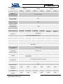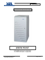
1
GREEN POINT
TECHNICAL SPECIFICATIONS
GREEN POINT
10-15-20kVA single-phase / single-phase
10-15-20kVA three-phase / single-phase
SP121E Rev. 000 Siel S.p.A.
Issued date: 2005-05-06
Pag. 1 of 42
GREEN POINT
Table of contents
..1.. OBJECTIVE
3
..2.. DESCRIPTION OF THE SYSTEM
3
..3.. APPLICATIONS
4
..4.. CHARACTERISTICS
4
..5.. REFERENCE STANDARDS
10
5.1 Main reference standards
10
5.2 Standards relating to systems and installation
12
..6.. INSTALLATION INSTRUCTIONS
6.1 Electrical system requirements
13
13
6.1.1 Protections
13
..7.. SYSTEM BLOCK DIAGRAM
16
7.1.1 Block diagram of the UPS 10÷20kVA
16
17 7.2 Options
17
7.3 Operating modes
19
..8.. INTERFACING
22
8.1 Remote signals and command connectors
22
8.2 EPO (Emergency Power Off command
22
8.3 DB15 Female
22
8.4 DB9 female
23
8.5 DB9 male
23
..9.. OPTIONS
24
9.1 Summary table of the options available
24
9.2 Communication software
25
..10.. CONTROL / DISPLAY PANEL
27
10.1 LED Panel
27
10.2 Liquid Crystal Display ( LCD )
29
10.3 List of the information output on the LCD display
29
10.4 Alarm messages
30
..11.. VIEWS OF THE UPS
11.1 Front and rear view of the UPS
34
34
..12.. TECHNICAL DATA
35
12.1 Models
35
12.2 Back-up expansion modules
36
12.3 Summary data sheets of models 10-20kVA
SP121E Rev. 000 Siel S.p.A.
Issued date: 2005-05-06
3742
Pag. 2 of 42
GREEN POINT
1
- OBJECTIVE
This technical document has been produced to be used by UPS system designers and installers.
The objective of this document is to provide and illustrate:
-
2
the technical information required to enable you to choose the correct UPS to suit your needs
the information required to set up and configure the system
the information concerning the installation and location of the UPS
the information the UPS displays locally to the user or to the monitoring systems it is connected to
(E.g. control centres, etc.)
a list of the possible options available to configure the UPS to the operators specific requirements
- DESCRIPTION OF THE SYSTEM
The GREEN POINT range of UPS has been designed to offer a high level of versatility and reliability.
Utilising the latest On Line double conversion (VFI) technology, meaning that the load is constantly supplied by
the alternating current (AC) from inverter, the UPS first converts the alternating current from the mains supply
into direct current (DC) and then back to AC again to ensure a perfectly sinusoidal, stable and filtered output in
terms of voltage and frequency. The frequency and voltage are constantly monitored using microprocessor
digital control, this control ensures true independence of the input power supply, with input and output filters
that significantly increase the extent to which the load is protected from mains supply borne transients, current
surges and noise. The GREEN POINT range is available in 10-15-20kVA single/single-phase or three/singlephase.
In terms of technology, performance (standard Economy Mode selectable), reliability, diagnostics (LCD display
with 128 alarms as standard), RS232 interface, EPO input and slot for network interface, the GREEN POINT is
the finest solution available for providing uninterruptible power to sensitive and vital “mission critical” loads and
safety systems (electro-medical).
To enable easy installation, the single-phase output version can be connected to either a single or three-phase
mains power supply.
The range
The GREEN POINT range consists of the following models:
MODEL
DESCRIPTION
GP 10000
10kVA three-phase or single-phase input (selectable) / single-phase output
(only parallel configuration)
GP 15000
15kVA three-phase or single-phase input (selectable) / single-phase output
GP 20000
20kVA three-phase or single-phase input (selectable) / single-phase output
SP121E Rev. 000 Siel S.p.A.
Issued date: 2005-05-06
Pag. 3 of 42
GREEN POINT
3
- APPLICATIONS
Personal computers
Small IT networks
Local Area Networks (LAN)
Workstations
Servers
Point of sale (POS) systems
Data centres
Industrial PLC’s
Cash registers
Electro-medical equipment
Emergency devices (lights/alarms)
Telecommunications equipment
E.Business (server Farms, ISP/ASP/POP)
4
- CHARACTERISTICS
High levels of supply stability
The system provides a filtered, stable and reliable voltage (On Line double conversion VFI technology in
accordance with European standard IEC62040-3) with filters for suppressing atmospheric and mains borne
disturbances.
The On Line technology provides the maximum protection for the connected loads. The double conversion
stage filters and stabilises the input voltage, and then reproduces it free of any disturbances such as
overvoltages, variations in frequency and voltage, noise, etc.
The IEC62040-3 standard defines this technology as VFI (Voltage and Frequency Independent), meaning that
the output voltage and frequency are completely independent of any variations or disturbances caused to the
incoming mains supply.
High degree of protection against current surges (6KV in accordance with EN61000-4-5)
The GREEN POINT range has been tested by subjecting them to massive overvoltage and current surges on
the input. The current surge used has a leading edge of 1.2 microseconds and a trailing edge of 50
microseconds, with the maximum energy of 300 Joules. The standard (EN61000-4-5) states that these current
surges can reach up 6kV.
High levels of reliability and redundancy
Modular power supply: parallel connection
Maximum reliability and availability from the power supply, with the possibility to connect up to 8 systems in
parallel, used to provide either redundancy (N+1) or total power. The range has been specifically designed to
enable the user to install them in parallel with other systems of the same type, during the first installation or at a
later date (retrofit).
SP121E Rev. 000 Siel S.p.A.
Issued date: 2005-05-06
Pag. 4 of 42
GREEN POINT
The parallel system modification does not require the UPS to be manually calibrated in any way, the calibration
of the systems is handled automatically by the microprocessor digital control system, this controls the exchange
of information and ensures that the load distribution between the various UPS systems is equal. This method of
control noticeably increases the overall reliability and efficiency of the system (it is common knowledge that
most manually calibrated systems tend to degrade over time due to temperature or vibration).
The GREEN POINT can be connected in parallel to increase the total amount of power available from the
system (known as a total power system) or to improve the level of reliability/redundancy, therefore if a fault
occurs to one of the UPS systems the supply to the load will remain supplied by the operational system (known
as a parallel redundant system).
“Digital” reliability
High level of UPS reliability (total microprocessor control).
The digital control system dramatically improves the overall reliability and efficiency of the UPS; resulting in a
reduction in the number of electronic components required, the microprocessor controls and monitors all of the
functions of the UPS from one common control card. The control card can be used across a number of various
systems, even systems in different ranges, thereby increasing the productivity and reliability of the range.
Suitable for any type of load
The system is suitable for powering both IT or industrial loads, thanks to an output power factor of 0.8.
The UPS can provide an active power output rated at Pn x 0.8, and can therefore support industrial loads (which
typically have a high power factor)
Low Power consumption
With an efficiency level of 92%, thanks to the digital control and IGBT technology. This technology enables the
system to considerably reduce the energy wasted. In particular, thanks to the high switching speeds and low
losses of the IGBT (Isolated Gate Bipolar Transistor) used in the inverter output stage, results in a high level of
efficiency even at low loads (the efficiency is hardly effected with loads from 25 to 100% of the rated value). The
reduced number of components within the system further helps to save energy.
“Economy Mode” and “Smart Active Mode” function (for increasing efficiency up to 98%)
Economy Mode:
Enables the user to select the Line Interactive (VI) technology, this mode provides power to non sensitive
loads from the incoming mains supply for certain applications. In the event of a mains supply failure
occurring the load is automatically switched onto the inverter for continued operation. This function can
be programmed via the software or set manually from the UPS control panel. The voltage tolerance for
this function can be set from ± 5% to ± 25% and the frequency from ± 1% to ± 5%.
Smart Active:
Enables the user to allow the UPS to determine which method of operation (on-line or line interactive) is
suitable dependent on the quality of the incoming mains supply. If the mains supply is not within the
acceptable limits for both voltage and frequency, the UPS will supply power to the load from the inverter
SP121E Rev. 000 Siel S.p.A.
Issued date: 2005-05-06
Pag. 5 of 42
GREEN POINT
(on-line). When the mains supply returns to within the acceptable limits, the system will first ensure that
the supply remains stable, before switching the load back onto the mains supply.
During both of these operating modes, the load is powered directly from the mains supply via the bypass.
However, due to the EMI filters in both the input and output, the mains supply is filtered and therefore free of
any electrical disturbances.
If the incoming mains supply fails, the load is supplied directly by the inverter. This function reduces energy
consumption as when the mains supply is present, the inverter is off.
Flexibility of operation
Daily timer:
Enables the user to configure the UPS operational times on a daily basis, thus optimising the power
consumption with respect to the time of day and importance of the load applied. This is configurable from the
control panel or via software.
Emergency Stand-by function
The GREEN POINT can function as an emergency stand-by device. This particular operating mode is
configurable from the control panel, and enables the supply to emergency lighting. The UPS remains off under
normal operating conditions and only activates the output when the mains power supply fails.
The inverter switches on within 320ms in accordance with the current regulations, which stipulates a maximum
delay time of 500ms, the inverter starts up gradually, thus preventing any sudden current surges.
This operating mode enables considerable energy savings, as the inverter is off under normal conditions and
therefore does not consume any energy. In addition, the system does not need to be over-sized, as the gradual
start up of the inverter prevents any current surge problems that might otherwise occur.
Auto-off function:
This function is programmable from the front control panel, and enables the system to automatically switch the
load onto the by-pass line when the connected load on the UPS falls below a preset value (configurable). This
mode reduces the energy wasted by switching the inverter stage off when the system is powering non-critical
loads. When the load is increased the UPS returns to on-line mode. This function is also useful for avoiding
unnecessary deep battery discharges, where there is no load connected during a mains supply failure.
Frequency auto sensing:
The UPS automatically selects the output frequency based on the input frequency ( 50 – 60 Hz )
Frequency converter function:
The UPS can be configured to function as a frequency converter, therefore when the input frequency is 50Hz the
output frequency can be 60Hz and vice versa. During this mode of operation the automatic by-pass is
deactivated.
Auto-Restart:
SP121E Rev. 000 Siel S.p.A.
Issued date: 2005-05-06
Pag. 6 of 42
GREEN POINT
The UPS can be configured to automatically restart after a mains supply failure or after the batteries have
become fully discharged. The Auto-Restart function may be delayed using the built-in software.
Cold Start (no battery):
Enables the UPS to be switched on during the absence of the mains supply (optional).
Low impact on the mains power supply
Power factor correction (UPS input factor close to 1):
The UPS absorbs power from the incoming mains supply with a power factor close to 1, even if the systems
supplied by the UPS have a power factor inferior to this. For example, if the UPS supplies a piece of IT
equipment with an input power factor of 0.65, the UPS input power factor will still remain close to 1, ensuring
that any mains supply power factor correction banks are not overloaded.
Sinusoidal absorption (option)
The UPS draws a sinusoidal current from the mains supply, meaning that the system has a very low impact on
the mains supply and, as a consequence, on the other pieces of electrical equipment connected to it.
Maximum battery reliability
The system compensates for any variations in temperature whilst recharging the batteries, as temperature
represents the greatest threat to the overall life and performance of the batteries. The recharge voltage is
temperature dependent – the higher the temperature, the lower the recharge voltage will be. This system
ensures that the batteries operate effectively, efficiently and prolongs their life.
High level of battery reliability (automatic battery test).
The UPS carries out battery tests automatically; these tests enable the system to periodically check the
efficiency of the batteries in order to prevent any faults occurring to them. The test does not in any way
compromise the supply to the connected equipment, and given the short duration (seconds), it does not affect
the life or the back-up time of the batteries.
The period between and the duration of the test can be configured via the control panel, or the test can be
completely deactivated.
The batteries are also protected against prolonged slow discharge. An electronic device automatically
disconnects the batteries if the discharge period is too long (for example when the UPS is operating on back-up
either with no load or with very low loads). This protects the batteries from discharging completely, which
inevitably accelerates the ageing process.
Reduced noise:
The use of high speed IGBT switching technology and controlled ventilation in relation to temperature and load
applied, ensures a very low operational noise with very little impact on the surrounding environment .
Complete self diagnostic capability
The internal event log providing 128 signals, status and alarms all via the standard multilingual LCD display.
The information provided enables the user to accurately identify any problem relating to the system or to the
operating environment (variations in the mains, overtemperature, overloads, etc.).
SP121E Rev. 000 Siel S.p.A.
Issued date: 2005-05-06
Pag. 7 of 42
GREEN POINT
Easy to install and maintain
Simplified installation:
The UPS can be connected to either a single-phase or three-phase power supply without any internal
modifications necessary.
Castors to ease installation, movement and maintenance of the system .
Adjustable output voltage via the control panel. This enables the output voltage from the system to be increased
to compensate for the drop of voltage through the cables to the load, guaranteeing the rated voltage to all
users. This is particularly important in systems that require long supply to load cables.
External manual By-Pass:
The UPS can be connected to an external manual by-pass system, therefore the external by-pass can be
integrated and monitored by the UPS.
Compact dimensions and quick maintenance (reduced MTTR):
Simplified access to the electronics and power components.
The internal batteries (models 10-20kVA) can be easily accessed from the front of the system, and therefore can
be easily checked, tested or replaced without the need to access them from the side or rear.
As there is no requirement to provide a space at the side or the rear of the system to perform maintenance
work, a reduction in the overall size of the system is achieved .
Further space saving is achieved due to the front to rear ventilation.
Advanced Communication
Monitoring and shut down software included
Greenshield provides an efficient and intuitive system for controlling and monitoring the UPS, displaying all of
the most important information, such as input voltage, applied load, battery capacity, etc. using a series of bar
charts.
The software is able to provide detailed information even if the UPS has malfunctioned, enabling the user to find
out why the fault has occurred and when.
Greenshield has been developed using a client/server architecture that renders it flexible and easy to use, with
multilingual support and on line help.
The Greenshield software is provided free of charge with an SNMP agent, this version will operate on Windows
95, 98, 2000, Windows 2003 Server, Me, Xp, NT4.0, Novell, Mac OS, Mac Osx, Mac Os 9.x & Linux operating
systems.
SP121E Rev. 000 Siel S.p.A.
Issued date: 2005-05-06
Pag. 8 of 42
GREEN POINT
The software enables the user to programme the automatic start-up and shutdown of the system on a weekly
basis.
The UPS also contains the following hardware interfaces:
-
double RS232 serial port
voltfree contacts interface
slot for the installation of a network adaptor
EPO (Emergency Power Off) contact for UPS emergency power off using
a remote emergency button.
SP121E Rev. 000 Siel S.p.A.
Issued date: 2005-05-06
Pag. 9 of 42
GREEN POINT
5
- REFERENCE STANDARDS
5.1 Main reference standards
The company quality system has been certified as conforming to ISO 9001 (Certificate ITALCERT No.
005/03). This covers all of the procedures, operating methods and controls from the design stage to
production, sales, through to the after sales service support.
This certification guarantees the following aspects to our customers:
-
the use of quality materials
rigorous standards in production and testing
receptiveness and openness to our customers
constant support of all our customers
As well as conforming to this certification, the company also produces “state of the art” products, as
dictated by the requirements of the standards quoted below.
The advances that have taken place in Information Technology systems, means that the power systems
used to power them must be able to provide an absolutely precise, and even more importantly, absolutely
reliable source of power. The standards produced by IEC/CENELEC in the IEC/EN62040 series, cover all
aspects of the product: safety, electromagnetic compatibility and performance.
STANDARDS
EN62040-1:
Uninterruptible power supply systems (UPS): general provisions and safety provisions
EN62040-1-1:
Uninterruptible power supply systems (UPS): general provisions and safety provisions used in areas
accessible to the operator
EN60950 (CEI74-2):
ITE (Information Technology Equipment) safety
EN50091-2:
Uninterruptible power supply systems (UPS): electromagnetic compatibility provisions.
EN50081-2:
Electromagnetic compatibility (immunity)
IEC61000-4-2:
Immunity: Electro Static Discharge (ESD)
SP121E Rev. 000 Siel S.p.A.
Issued date: 2005-05-06
Pag. 10 of 42
GREEN POINT
IEC61000-4-3:
Immunity: electromagnetic fields
IEC61000-4-4:
Immunity: transient overvoltages (BURST)
IEC61000-4-5:
Immunity: current surges (Surge)
IEC61000-4-11:
Low frequency disturbances
EN50141:
Induced radio interference
EN55022:
Radio frequency disturbance
EN62040-3
Uninterruptible power supply systems (UPS): performance provisions and test procedures.
EN50171:
Central supply systems for emergencies (CSS)
IEC146 (CEI22):
Semiconductor electronic converters
IEC529 (CEI70-1):
Degree of protection of casings
European Directives
73/23
Low voltage directive enforcing use of the CE marking from 1/1/97. This directive concerns all issues of
safety associated with the equipment.
89/336
Electromagnetic compatibility directive enforcing use of the CE marking from 1/1/96. This directive
concerns all issues of immunity and emissions relating to the UPS once installed.
SP121E Rev. 000 Siel S.p.A.
Issued date: 2005-05-06
Pag. 11 of 42
GREEN POINT
5.2 Standards relating to systems and installation
The above product regulations refer specifically to uninterruptible power supply systems. It is these
regulations that manufacturers of uninterruptible power supply systems are obliged to adhere to.
However, with regard to the electrical system, the installer must refer to other standards.
− standard CEI 64-8 ( HD384/IEC60364 )
for electrical systems in general
− standard CEI 64-8/7 variant 2:
for installation in hospital environments
− standard CEI 11-20:
for systems with UPS machines connected to category I or II networks
− standard CEI 17-13 ( EN60439-1 )
relating to control equipment
− standard CEI 21-6/3 (EN50272):
for battery installation
− CEI 20:
for electrical cables
SP121E Rev. 000 Siel S.p.A.
Issued date: 2005-05-06
Pag. 12 of 42
GREEN POINT
6
- INSTALLATION INSTRUCTIONS
6.1 Electrical system requirements
6.1.1 Protections
UPS INTERNAL PROTECTION
The size of the circuit breakers and fuses positioned in the UPS input/output lines are shown in the table below
(refer to the block diagram section for an explanation of the abbreviations). Any fuse that requires replacement
must only be replaced with a fuse of the same type and rating, as indicated in the table below.
UPS with SINGLE-PHASE OUTPUT:
Switches and Internal Protections
UPS
Type
[kVA]
10
15
20
Non-automatic switches
Fuses
UPS
Input
UPS Output /
Maintenance
Rectifier
Input Fuse
SWIN
63A (4P)
100A (4P)
100A (4P)
SWOUT/SWMB
63A (2P)
100A (2P)
100A (2P)
20A gR(10x38)
30A gR(10x38)
30A gR(10x38)
Input
Current
[A]
FBAT
FBY
Max
30A gR(10x38) 50A gR(14x51)
51
30A gR(10x38) 63A gG(22x58)
67
30A gR(10x38) 100A gG(22x58)
74
Battery Fuse
Bypass Fuse
Output
Current
[A]
Rated
43
65
87
UPS INPUT PROTECTION
When installing the UPS input protection devices, the maximum current drawn will be dependent on the
operational mode of the system when a fault occurs, therefore the following two operational modes must be
taken into account.:
− During “NORMAL OPERATION”, the power to the load is supplied by the mains input via the
converter, and therefore the maximum input current drawn is that shown in the table above (under
the heading “Input current max) .
− During “BYPASS OPERATION”, the power to the load is supplied directly via the by-pass line,
therefore the maximum input current drawn is limited by the rating of the bypass fuse shown in
table above (under the heading “Bypass fuse FBY).
SP121E Rev. 000 Siel S.p.A.
Issued date: 2005-05-06
Pag. 13 of 42
GREEN POINT
Differential (Residual Current Device (RCD))
In the standard version, where no input isolation transformer exists, the mains supply input neutral is
connected to the UPS output neutral. The UPS does alter the arrangement of the neutral regime within
the system, as a result, the electrical systems both up stream and down stream are identical.
Additional differential (RCD) devices may be installed on the output of the UPS, corresponding to
those installed on the input.
The differential devices installed on the system input must have the following characteristics:
§
§
A differential current of not less than 100mA (to avoid nuisance tripping)
type A or type B with delay equal to or greater than 0.1 s
The UPS rated output current is indicated in the previous table (under the heading “Output current
rated”)
UPS OUTPUT PROTECTION, SHORT CIRCUIT AND DISCRIMINATION
Short circuit
During a fault within the load or a short circuit, the UPS will limit the amount and the duration of the
current supplied (current limited), in order to protect the UPS inverter output(short circuit current).
The amount of current available will depend upon the operating mode of the UPS at the time of the
fault.
UPS in Normal Operation mode: The load is instantly switched onto the by-pass supply, thus
guaranteeing the values indicated in the technical data section, before the FBY fuse(s) intervenes.
UPS in Battery Operation mode: The UPS protects itself by supplying an output current of
approximately 2 times the rated current for 0.5s.
Discrimination
The following table provides an indication as to the maximum rating and type of fuse that can be
discriminated by the UPS, the table contains two values for each size of UPS, the recommended fuses
are dependent on the operational mode of the UPS when the fault or overload occurs, these being
either Normal Operation or Battery Operation.
UPS with single-phase output
kVA Rating
Max output fuse size & type [A]
gG
Discrimination in Battery Operation mode
10
SP121E Rev. 000 Siel S.p.A.
Issued date: 2005-05-06
10
aM
gG
6
16
15
aM
gG
8
20
20
aM
10
Pag. 14 of 42
GREEN POINT
CONNECTING THE SUPPLY AND LOAD
UPS with single-phase output (three-phase + neutral input)
PE
L1
L2
L3
N
L
N
PE
Refer to the table below for the recommended cross sectional area
of the input and output cables. The figures within the brackets are
the maximum sizes that may be connected to the system terminals.
Size. [mm²]
INPUT
L1 L2
L3
N
L
N
PE
PE
INGRESSO
INPUT
USCITA
OUTPUT
kVA
10
15
20
L1
10(50)
16(50)
25(50)
L2/L3
4(50)
6(50)
10(50)
OUTPUT
N
10(50)
16(50)
25(50)
PE
10(50)
16(50)
25(50)
L1/N
10(50)
16(50)
25(50)
UPS with single-phase output (single-phase input)
To operate the UPS with a single-phase input, the jumper (supplied) must be fitted across the three live input
terminals (L1, L2, and L3) as shown below.
Refer to the table below for the recommended cross sectional area of the input and output cables. The figures
within the brackets are the maximum sizes that may be connected to the system terminals.
Size. [mm²]
INPUT
PE
L1
L2
L3
L
N
N
L
N
L
PE
kVA
10
15
20
L1
10(50)
16(50)
25(50)
N
10(50)
16(50)
25(50)
OUTPUT
PE
10(50)
16(50)
16(50)
L1/N
10(50)
16(50)
25(50)
N
PE
PE
INGRESSO
INPUT
USCITA
OUTPUT
SP121E Rev. 000 Siel S.p.A.
Issued date: 2005-05-06
Pag. 15 of 42
SP121E Rev. 000 Siel S.p.A.
Issued date: 2005-05-06
Optional
external battery
Batterie estern e
opzionali
Output 1Ph version
N
Version e con uscita 1Ph
Input/ingresso
230V 1Ph+N
or / o
400V 3Ph+N
-
N
+
FBAT
FB02
FB01
Internal Battery
Batterie interne
SW IN
TL R
+N
-
Converter
TL I
Signallings and comm and panel
Pannello comandi e segnalazioni
Control circuit with processor
Ci rcuiti di controllo con microprocessore
Inverter
T A back- fe ed
pr ote ction
TA o ut
4
1 -9
1 -9
D B9
ma le /ma schi o
8
7
1
2
15
1
11
10
3
14
6
13
5
12
DB9
fema le/femmin a
D B15
fe ma le /fe mmi na
SW OUT
SWM B
Se gna lazi oni
e c oman di re moti
EPO
RS 2 32 -2 l ine ----------- for Mo de m
R S 23 2 -1 li ne ---- ------- fo r PC
S to p in ve rte r
S to p UPS
C ommo n
+12 V a ux.
( 10 0mA ma x.)
B ypa ss
E nd Ba tte ry di scha rge
p rea la rm
Fi ne s car ica batte ria
Re mo te co ntro l
a nd si gna ls
Output 1Ph version
uscita versione 1F
230 1Ph+ N
Output 3Ph version
uscita versione 3F
400V 3Ph+N
Ba tte ry di sch arge
B atteri e i n sca ric a
N
L(* )
> 7.1.1 Block diagram of the UPS 10÷20kVA
L 1,L 2,L 3 In the thre ep has e ve rsi on / ne lla v ers io ne trifa se L 1,L 2,L 3.
Output 3Ph versionn
Version e con uscita 3Ph
Input/ingresso
400V 3Ph+N
L(* )
Bypass
7
Inpu t Filter
Filtro ingresso
FBY
GREEN POINT
- SYSTEM BLOCK DIAGRAM
Pag. 16 of 42
Output Filte r
Fil tro usc ita
GREEN POINT
7.2 Options
Isolating transformer
Back-up extension
Battery rechargerRemote
LED display
Net Adapter
USB Converter
Dual input
Led remote mimic panel
Remote mimic panel with
Parallel
display
Active filter
LEGEND :
1) Automatic By-Pass:
The automatic by-pass is an SCR (static) device that automatically switches the UPS output onto the incoming
mains supply in the event of an overload and/or a fault within the UPS.
Due to the SCR technology used, this operation occurs without any interruption in the supply to the load. The
system is equipped with an auxiliary redundant power supply to receive power even if the primary power supply
malfunctions.
2) Output contactor
The output contactor can automatically disconnect the UPS inverter output from the load in the following
scenarios:
a) During Line interactive mode (economy or Smart Active Mode)
b) During by-pass mode whilst on-line
c) If a fault occurs with the inverter or if the Emergency Power Off (EPO) button is pressed.
3) Battery charger
A typical recharge takes between 6 and 8 hours depending on the initial charge state of the batteries and the
size of the installed battery charger. The battery charger is deactivated when there is no mains supply present.
During the battery recharge cycle by the dedicated battery charger, the voltage and current are perfectly filtered
and stabilised, free from any alternating components (ripple) that may damage the efficiency or the life of the
batteries.
In addition, the battery recharge is temperature compensated. The greater the temperature, the lower the
recharge voltage, as recommended by the battery manufacturers, which considerably prolongs the overall life
and efficiency of the batteries.
4) Interface
The UPS is equipped with two RS232 interfaces, volt free contacts, input signals (by-pass and isolated
SP121E Rev. 000 Siel S.p.A.
Issued date: 2005-05-06
Pag. 17 of 42
GREEN POINT
emergency power off (EPO) as standard (see interface section)
5) Slot for network interface or other communications cards
The expansion slot enables the user to insert additional communications devices such as SNMP interfaces
(network adaptor card) or an auxiliary RS232 interface card/duplexer.
6) Control and display panel
The control and display panel provides the user with all of the visual (LED and LCD) and acoustic (buzzer)
signals regarding the operational status of the UPS. This panel also enables full control, monitoring, diagnosis
and personalisation of the UPS through the easy-to-use menu system accessed on the panel (refer to the
control panel section).
7) Input/output filters
During Normal Operation, the input/output filters eliminate high frequency disturbances and protect both the
UPS and the connected loads from any mains borne disturbances. These filters also ensure that any
disturbances created by the UPS or the connected loads do not affect any other user.
During both “Line interactive” and “By-pass” modes, the filters ensure that the connected loads are constantly
protected against disturbances from the mains power supply.
8) Converter (input stage)
During Normal Operation mode, the converter changes the mains AC voltage into a constant DC voltage,
suitable for both the inverter and the battery charger. When the mains supply is absent, it takes power from the
batteries, to provide the inverter with a constant voltage.
In the single-phase output versions the converter may either be connected to a 230V single-phase supply or
400V three-phase with neutral supply. The option of either a single or three-phase power supply can be made
during the installation.
The converter operates as a PFC (Power Factor Correction) device, providing an input power factor close to 1.
The UPS therefore has a correction element, which directly benefits the electrical system, therefore no
correction capacitors are required.
9) Inverter (output stage)
The inverter converts the direct current into a stable sinusoidal alternating current, which is used to power the
load. The load is always powered by the inverter when the UPS is in “on line” mode.
The inverter is single-phase , based on IGBT (Isolated Gate Bipolar Transistor) technology. The IGBT enables
high switching frequencies (up to 20kHz) thus reducing power consumption and audible noise levels (in
general, noises above a frequency of 16KHz are practically inaudible to the human ear).
10) Static by-pass
This device automatically switches the power supplied to the load between the inverter and the by-pass line and
vice versa. It consists of static (SCR) components that ensure zero switching time.
SP121E Rev. 000 Siel S.p.A.
Issued date: 2005-05-06
Pag. 18 of 42
GREEN POINT
The static bypass can support overloads greater than those supported by the inverter and enables the load to
be powered even if an internal fault within the UPS occurs.
The bypass has one fused at the input to the UPS.
11) Back feed protection
The back feed protection is installed in series with the bypass SCRs. When the mains power supply fails, and in
the event of a fault occurring with the SCRs, the back feed protection device prevents any current that could
cause an electric shock from back feeding to the incoming power supply connections.
Furthermore, when a mains supply failure occurs, an electromagnetic switch positioned at the rectifier input
opens, thus preventing any current back feed onto the electrical system prior to this point.
This device must be installed in electrical systems in accordance with the new CEI 11-20 regulation (I and II
category systems). This enables the user to work on the incoming power supply, after the power supply to the
UPS has been switched off via the supply isolator, and therefore no risk of any current back feed occurring from
the UPS.
12) SWMB (Maintenance by-pass), SWIN, SWOUT
The SWMB maintenance bypass switch directly connects the input to the UPS to the output load, thus
bypassing the internal sections of the UPS, the switch connects all of the incoming conductors (including the
neutral) to the corresponding output conductors without interruption to the load. Whilst the SWMB switch is
closed, the SWOUT, SWIN and FBAT switches can be opened, which enables the user to safely carry out
maintenance work within the UPS, whilst power to the load is maintained.
This method of operation is necessary for UPS systems of a certain size, where maintenance work is often
carried out on site, and therefore supplied as standard within the UPS.
The maintenance by-pass switch enables the load to be continually supplied, without altering the electrical
system. The bypass switch can also be used to re-connect power to the connected load in an event of an
emergency for whatever reason (overloads, high ambient temperature, total failure etc.), and can be left
switched on until such time as the UPS resumes normal operation condition.
The manual by-pass line is sized in accordance with the rated output of the UPS.
The UPS also enables the integration of an external maintenance bypass switch, therefore when the external
bypass is activated the UPS can report the condition and take the appropriate action.
7.3 Operating modes
The UPS can be configured to operate in one of the three general operating modes:
-
ON-LINE;
-
STAND-BY ON (equivalent to line interactive mode).
-
Stand-by
The “Battery Operation mode”, “By-pass Operation mode” and “Maintenance By-pass Operation
mode” are common to all three of these system configured modes.
SP121E Rev. 000 Siel S.p.A.
Issued date: 2005-05-06
Pag. 19 of 42
GREEN POINT
ON - LINE
With the factory default setting, the UPS goes into ON LINE mode when switched on.
Display
Power
message
supply
NORMAL
OPERATION
ok
SWIN
FBY FBAT SWOUT SWMB
on
on
on
on
Led
Led
Led
Led Buzzer
BATT
IN
OUT
BY
off
on
on
off
off
off
MAINS present and load powered.
The load is constantly supplied by the inverter with a stabilised and regulated voltage and frequency. If
a fault with the incoming mains supply occurs the UPS will instantaneously switch over to batteries,
which provide the power to the inverter and therefore maintains the power supply to the load. The
battery is then automatically recharged when the mains supply returns.
During either of these two operational conditions the inverter constantly supplies power to the load with
a stabilised and regulated voltage and frequency, ensuring that the load has a high degree of immunity
to disturbances etc, due to the double conversion. In the event of mains failure, no disruption in the
supply to the load will occur as the transfer is instantaneous.
STAND-BY ON
The STAND-BY ON mode and the by-pass line tolerance range must be set using the control panel.
The standby-on function reduces the energy dissipated by the system
Display message
NORMAL OPERATION
MODE STBY=ON
Power
supply
ok
SWIN FBY FBAT SWOUT SWMB
on
on
on
on
off
Led
Led
Led
Led Buzz
BATT
IN
OUT
BY
er
off
on
on
on
off
The Converter remains active and the batteries are kept charged:
The switching time between the inverter and the by-pass line can be either set to immediately (Economy
Mode), or delayed up to a maximum of 180 minutes (Smart Active Mode). For the system to switch the
load onto the by-pass line, the bypass supply must be within the configured acceptable range for the
pre determined time set.
The system remains on the by-pass line for as long as the voltage and frequency fall within the
acceptable predetermined range. The input “IN” (green), output “OUT” (green), by-pass “BY”(yellow)
LEDs are permanently lit on the display panel.
During this operating mode, energy dissipated is significantly reduced (efficiency = 98%)
If the by-pass line fails or the voltage or frequency exceed the acceptable range, the load is
automatically switched onto the inverter output.
SP121E Rev. 000 Siel S.p.A.
Issued date: 2005-05-06
Pag. 20 of 42
GREEN POINT
STAND-BY FUNCTION:
The UPS can be programmed to operate in stand-by mode. During this mode, the UPS output remains
off whilst the mains supply is present and activates only when the mains supply fails.
The inverter start up is progressive (320 msec), to prevent current surges occurring due to loads such
as lights etc.
SP121E Rev. 000 Siel S.p.A.
Issued date: 2005-05-06
Pag. 21 of 42
GREEN POINT
8
- INTERFACING
8.1 Remote signals and command connectors
The following connectors are situated on the rear. Refer to the “VIEWS OF THE UPS” section for details.
1 x EPO (emergency power off ) connection point;
1 x DB15 female REMOTE;
1 x DB9 male RS232-1;
1 x DB9 female RS232-2;
1 x Aux Slot for SNMP card etc.
8.2 EPO (Emergency Power Off command)
The EPO operates a normally closed system and by opening the link will force the UPS into an
emergency power off command.
Using this input, the UPS can be shut down remotely in the event of an emergency by pressing a single
emergency button. The EPO switches the UPS off which will remain in this state until reset.
8.3 DB15 Female “Remote”
This connector consists of:
1 x 12Vdc 80mA(max) power supply
3 x voltage-free alarm contacts
2 x Inverter and UPS shutdown commands
The pin layout is as follows ( see figure ):
BATTERY LOW = END OF DISCHARGE PRE-ALARM (the low battery
warning time can be configured )
BATTERY DISCHARGING = BATTERY DISCHARGING (mains failure)
BY-PASS / FAULT = BY-PASS/FAULT
The position of the contacts shown is during a non alarm state
(NORMAL OPERATION).
The contact rating is 42V @ 0.5A(max).
REMOTE COMMANDS
2 commands are available:
BYPASS with INVERTER STOP– by connecting pin 8 to pin 15 (for at least 2 seconds) used for external
bypass commands.
TOTAL STOP – by connecting pin 7 to pin 15 (for at least 2 seconds) the system will shut down.
SP121E Rev. 000 Siel S.p.A.
Issued date: 2005-05-06
Pag. 22 of 42
GREEN POINT
8.4 DB9 female “RS 232-1” PC connection
Can be used to connect the UPS to a computer 9 pin DB9 type male connector. The UPS transmission
protocol preset by the factory is as follows: - 9600 baud, - no parity, - 8 bit,- 1 stop bit.
The transmission speed can be configured using the CUSTOMISATION menu on the panel from 1200 to
9600 baud.
Recommended transmission speeds in relation to transmission distance:
9600 baud 50m, 4800 baud 100m, 2400 baud 200m, 1200 baud 300m
To connect the UPS to a PC, use a shielded pin to pin cable (AWG22÷28) and only connect the shielding to
the computer end.
8.5 DB9 male “RS 232-2” MODEM connection
Can be used to connect the UPS to a Modem. 9 pin DB9 type male connector. The transmission protocol
preset by the factory is as follows: - 9600 baud, - no parity, - 8 bit,- 1 stop bit.
The transmission speed can be configured using the CUSTOMISATION menu on the panel from 1200 to
9600 baud.
Recommended transmission speeds in relation to transmission distance:
9600 baud 50m, 4800 baud 100m, 2400 baud 200m, 1200 baud 300m
To connect the UPS to a PC, use a shielded pin to pin cable (AWG22÷28) and only connect the shielding to
the computer end.
SP121E Rev. 000 Siel S.p.A.
Issued date: 2005-05-06
Pag. 23 of 42
GREEN POINT
9
- OPTIONS
9.1 Summary table of the options available
Description
Isolating transformer module 400V two-phase or 230V
single-phase, output 230V single-phase 10 kVA
Isolating transformer module 400V two-phase or 230V
single-phase, output 230V single-phase 15 kVA
Isolating transformer module 400V two-phase or
230Vsingle-phase, output 230V single-phase 20 kVA
Remote LED display
Remote LCD display
Communication software
Dimensions (HWD)
mm
Weight (Kg)
1200x555x750
140
1200x555x750
160
1200x555x750
188
Parallel kit (one per machine)
Active Filter (THDi <4%)
ISOLATING TRANSFORMER MODULE:
Enables the UPS input to be galvanically isolated from the output.
Also enables the change the neutral arrangements (from TT to TN, or from TT to IT, for example) to
increase the continuity of the power supply (IT system), or to increase the level of protection of the
users (TN system).
The transformer may be connected to the UPS input (single-phase/single-phase or three-phase/threephase version) or to the output (three-phase/single-phase version).
REMOTE LED DISPLAY:
Can be connected at a distance of up to 200m from the UPS, enabling the user to view the general
status of the UPS remotely in real time.
The remote display indicates the operation of the system:
§
§
§
green LED: normal operation
yellow LED: non critical alarm
red LED: alarm
The remote display also enables the sending of both the UPS switch on or the shutdown commands
remotely.
REMOTE LCD DISPLAY
The remote LCD display replicates the control and display panel of the UPS, therefore full control and
interaction with the UPS is possible remotely.
SP121E Rev. 000 Siel S.p.A.
Issued date: 2005-05-06
Pag. 24 of 42
GREEN POINT
9.2 - Communication software
MAIN CHARACTERISTICS
1) Sequential and prioritised shutdown:
Greenshield enables the user to shutdown the network without having to individually switch off each PC
or server, and before doing so, Greenshield will save the work that was being done regardless of the
application that was being used. The user may also define their own shutdown procedure and also
prioritise the shutdown of critical components within the system (such as vital and non vital servers).
2) Multiplatform compatibility:
Greenshield provides the user with a standard control and monitoring capability, using TCP/IP
communication protocol.
This enables the user to monitor computers that use different operating systems from a single console.
For example, not only could the user monitor a UNIX server from a PC with Windows 98, the user could
also connect to UPS systems situated in different locations by using either a dedicated network
(intranet) or the Internet.
3) Events scheduling:
Greenshield enables the user to define their own shutdown/switch off and on procedures, for the
systems that are connected to the UPS. Not only does this noticeably increase the degree of security of
the system, it also enables the user to make significant energy savings.
4) Message management:
Greenshield keeps the user constantly informed of the status of the UPS, whether locally or by sending
messages to users connected to the network. It is also possible to create a list of the people who will
receive messages by e-mail, fax and SMS should a fault or sudden blackout occur.
5) Integrated SNMP agent:
Greenshield contains an integrated SNMP agent for managing the UPS via SNMP. This agent is able to
send all of the information regarding the UPS and is capable of generating traps using the RFC 1628
MIB standard.
This enables the user to control the UPS using SNMP compatible workstations such as HP Open View,
Novell Managewise and IBM NetView.
OPERATING SYSTEMS SUPPPORTED
-
Windows 95, 98, Me, NT 4.0, Win 2000, Win 2003 Server, XP.
Novell Netware 3.x, 4.x, 5.x, Intra NetWare
IBM OS/2 Warp and Server,
Mac OS, 9.X, OSX
The most commonly available UNIX systems such as:
IBM AIX, HP UNIX, SUN OS SPARC, SUN Solaris INTEL and SPARC, SCO Unix and UnixWare,
Siemens SINIX, Silicon Graphic IRIX, Compaq True64 UNIX and DEC UNIX, Linux, BSD UNIX and
FreeBSD UNIX
GREENSHIELD SOFTWARE FUNCTIONS
1) Graphical monitoring of the UPS status
SP121E Rev. 000 Siel S.p.A.
Issued date: 2005-05-06
Pag. 25 of 42
GREEN POINT
Greenshield is the easy to use yet powerful program that enables the user to monitor and control the
UPS systems.
There are various graphical versions including Windows, Java, OS/2 and MacOS.
2) MACOS version
The Greenshield software is the only UPS control and shutdown software available for the Macintosh
that has a client-server architecture.
Enabling the user to access the Windows, Novell, IBM OS/2 and the most commonly available UNIX
operating systems, when using a TCP/IP network.
It also enables the user to support the NetMan series network agents to control the UPS via a network,
and furthermore, comes with multilingual support.
3) Detailed display of all the UPS data
Greenshield provides all the data required to make an accurate and swift assessment of the UPS
operation and status.
4) Block diagram and operating diagram of a UPS
Greenshield displays a block diagram of the UPS, thus providing the user with conceptual information
as to the status of the system.
5) Automatic saving of the events log and graphical display
All of the events regarding the operation of the UPS are saved and recorded, thus allowing the user to
monitor such data as the input voltage, applied load or the remaining back-up time available from the
batteries.
6) Alarm notification via E-MAIL and SMS
It is possible to configure Greenshield to automatically notify of an alarm via an e-mail or SMS message.
7) Programming the UPS commands
Enables the user to program all of the commands that would normally be carried out manually, to be
performed automatically, for example: shutting down or switching the servers back on, UPS battery test,
etc.
SP121E Rev. 000 Siel S.p.A.
Issued date: 2005-05-06
Pag. 26 of 42
GREEN POINT
10
- CONTROL / DISPLAY PANEL
10.1. LED Panel
BUTTONS
1. Help/Language selection
2. Measurements
3. Commands / selection / customisation
4. Events log
5. Audible alarm On/Off
6. Time / date
7. Scroll back
8. Scroll forward
Control / Display panel (10-20 kVA models)
Information on the UPS operating status is provided by:
- a Liquid Crystal Display (LCD), with variable contrast and two lines of 40 characters.
- four LEDs
"IN"
"OUT"
"BY"
"BATT"
power supply and by-pass line input
inverter output
by-pass line output
battery input
- an acoustic signal.
SP121E Rev. 000 Siel S.p.A.
Issued date: 2005-05-06
Pag. 27 of 42
GREEN POINT
LEDs
The LEDs can be either lit, flashing or off, thus providing immediate information on the UPS status.
IN LED (green): input supply.
Lit:
The input supply is within a preset range (voltage or Frequency);
Flashing:
The input supply is not within a preset range (voltage or Frequency);
Off:
No input supply present.
OUT LED (green): inverter output line.
Lit:
The UPS output is supplied by the inverter, if the BY (yellow) is also lit, the UPS
is in Stand by mode.
Flashing:
UPS output is supplied by the inverter with a load >100% or the SWMB switch
is closed.
Off:
When the system output has been switched onto the automatic internal bypass line, or the SWOUT switch is open.
BY LED (yellow): automatic by-pass output line.
Lit:
When the system output has been switched onto the automatic internal bypass line.
Flashing:
When the output load is greater than 100%VA, or when the manual by-pass
SWMB switch is closed.
Off:
When the system output has been switched onto the inverter or when the EPO
command is active.
BATT LED (yellow): battery line.
Lit:
When the batteries are supplying power to the inverter.
Flashing:
When either the "BATTERY VOLTAGE LOW PRE-ALARM" or the BATTERIES
DISCHARGED alarm OR SWB OPEN are active.
Off:
When the UPS is on and the batteries are charged or charging.
Acoustic signal
The buzzer can be activated or deactivated, with preferences saved to memory.
The buzzer sounds intermittently at 2 seconds intervals whenever there is an alarm of any kind.
The buzzer sounds continuously when the BATT LED (end discharge pre-alarm) flashes.
SP121E Rev. 000 Siel S.p.A.
Issued date: 2005-05-06
Pag. 28 of 42
GREEN POINT
10.2 Liquid Crystal Display ( LCD )
LCD display: status messages
During Normal Operation mode, where no specific information has been requested and/or no particular
command has been made using either the buttons on the control panel or via the RS232 remote line, the LCD
will display a number of basic messages.
It is possible to obtain further information, or perform commands, by accessing the sub-menus using buttons 1
– 8 of the control panel and following the instructions that appear on the screen.
10.3 List of the information output on the LCD display:
Selections
−
Help
−
Language selection (Italian – English – French – German - Spanish - Dutch - Swedish – Polish)
Measurements:
input voltage
input power
by-pass frequency
output frequency
output peak power
battery peak pulse current
inverter input voltage
inverter operation time
battery operation time
no of complete discharges
input frequency
by-pass voltage
output voltage
output power
battery voltage
battery discharge current
internal temperature (system/converter
/bypass/inverter/magnetic components)
by-pass operation time
no. of battery interventions
date of first activation
Commands
battery test
by-pass off
system off
display contrast
end discharge pre-alarm
Customisation
output voltage
batteries
end discharge pre-alarm
by-pass voltage tolerance
modem
output voltage compensation
line-interactive operating mode
auto off
by-pass frequency tolerance
Event Log
Enables the user to view up to 120 previous events . For each event, the measurements taken and alarms active
when the event occurred can also be seen.
SP121E Rev. 000 Siel S.p.A.
Issued date: 2005-05-06
Pag. 29 of 42
GREEN POINT
10.4 Alarm messages
The alarm messages that appear on the first line of the display panel are listed below. The alarm number in
brackets indicates the level of priority.
[1] DISTURBANCES ON THE BY-PASS LINE
This alarm is present whenever there is a disturbance on the by-pass line (such as a voltage peak or harmonic
distortion, whilst the voltage and frequency are correct).
[2] BY-PASS MANUAL, SWMB - ON or cable fault
The manual by-pass switch, or SWMB, has been switched on, preventing the system from returning to normal
operation. The load is powered by the by-pass line input and is not protected by the UPS.
“Cable fault” only refers to those UPSs that have been connected in parallel. The processor has detected an
error in the communications signals exchanged between the UPS systems connected in parallel and has
therefore switched the entire system on to by-pass mode.
[3] BY-PASS VOLT. FAIL or SWIN, FBY OFF
This alarm is present if :
−
−
−
the voltage on the by-pass line input is incorrect.
or the SWIN input switch is open.
or the fuse on the by-pass line is open or failed.
[4] MAIN LINE VOLTAGE FAIL or SWIN OFF
The incoming mains supply voltage is incorrect and the battery is therefore powering the load.
This alarm is present if one of the following conditions occurs:
−
−
the voltage or frequency of the converter supply line are not within acceptable limits
(see general characteristics).
SWIN switch is open.
[5] PRE-ALARM, LOW VOLTAGE ON BATTERY
This alarm is present if:
−
−
the battery voltage is less than the amount required to provide approximately 5 minutes of back-up (this
time is configurable).
or the residual back-up time is less than the amount that has been set.
[6] BATTERY DISCHARGED or FBAT OPEN
The UPS has performed a battery test while the mains supply is present and the result is negative.
[7] LOW VOLT. SUPPLY or OVERLOAD [W]
SP121E Rev. 000 Siel S.p.A.
Issued date: 2005-05-06
Pag. 30 of 42
GREEN POINT
This alarm is present if one of the following conditions occurs:
−
−
the incoming mains supply voltage is insufficient.
the output load, measured in active power [W], exceeds the rated value.
[8] OUTPUT OVERLOAD
Indicates that the power drawn by the load and provided by the inverter exceeds the permitted value. The value
indicated, expressed in %VA, exceeds 100%.
This alarm is activated whenever the peak current absorbed by the load exceeds the maximum value permitted.
When this alarm occurs the load should be reduced immediately. Otherwise the system will switch the load onto
the by-pass line, with a time delay inversely proportional to the size of the overload.
[9] BY-PASS FOR VA OUTPUT < AUTO-OFF VALUE
This alarm is activated whenever the power measured in %VA drawn by the load is less than the "AUTO-OFF"
value that has been set.
The %VA AUTO-OFF value is set to zero by the manufacturer (thereby disabling this alarm).
[10] INTERNAL FAULT: number
The various faults indicated are:
INTERNAL
INTERNAL
INTERNAL
INTERNAL
INTERNAL
INTERNAL
INTERNAL
INTERNAL
INTERNAL
INTERNAL
INTERNAL
INTERNAL
INTERNAL
INTERNAL
INTERNAL
INTERNAL
INTERNAL
INTERNAL
INTERNAL
INTERNAL
INTERNAL
INTERNAL
INTERNAL
FAULT 1
FAULT 2
FAULT 3
FAULT 4
FAULT 5
FAULT 6
FAULT 7
FAULT 8
FAULT 9
FAULT 10
FAULT 11
FAULT 20
FAULT 21
FAULT 22
FAULT 23
FAULT 24
FAULT 25
FAULT 26
FAULT 27
FAULT 28
FAULT 29
FAULT 30
FAULT 31
- Precharge circuit fault
- Inverter
- Inverter output contactor failure
- Booster output voltage
- SCR on bypass line
- Input contactor failure
- Internal power supply error on the control board
- Battery charger high voltage
- SCR battery
- Fault on parallel signal circuits
- Switching on inverter failure
- DC output voltage failure
- A UPS operating as slave has distorted current flow
- Parallel slave UPS has a different software version
- Parallel UPS with different number of output phases
- Transmission error from parallel master UPS
- UPS previously activated in parallel mode
- Switch over to bypass line failed
- Failure on bypass SCR power supply
- Input circuit with active filter failure
- Active filter communication failure
- Failure on temperature sensor
- Microprocessor failure
[11] TEMPORARY BY-PASS, WAIT
Indicates that the load is powered by the by-pass line and that the system is about to automatically return to
normal operation, where the load is powered by the inverter.
SP121E Rev. 000 Siel S.p.A.
Issued date: 2005-05-06
Pag. 31 of 42
GREEN POINT
This transitory phase occurs, for example, when the machine has just been switched on, or when it is waiting to
return to inverter mode after having been switched to by-pass mode due to an overload.
[12] BY-PASS FOR OUTPUT OVERLOAD (fixed or flashing message)
If the message is flashing then the alarm has been memorised.
Indicates that the by-pass line overload has been memorised.
The overload must persist for a certain amount of time in order for it to be memorised.
[13] BY-PASS COMMAND ACTIVE; 8=COMMAND OFF
This alarm is present when the system has been deactivated and switched on to by-pass mode using the
appropriate command on the keypad. The command is memorised even if the system is shut down due to
insufficient power supply.
When the power supply returns, the system will not return to normal operation until this command has been
removed.
[14] REMOTE BY-PASS COMMAND: ACTIVE
This alarm is present when the system has been deactivated and switched on to by-pass mode using the
appropriate command connected to the “remote command and signal” connector (EPO).
The command is not memorised and the system will return to normal operation when the command is removed,
assuming that there is a stable power supply to the system.
[15] OVERTEMPERATURE OR FAN FAILURE
This alarm is activated when the temperature of the system card, the inverter power modules, the rectifier power
modules or the output filter chokes exceeds the maximum permitted value.
−
This may be caused by the system operating temperature in an environment where the ambient
temperature is too high.
[17] INPUT PHASE SEQUENCE NOT OK
Indicates that the input phase sequence on the by-pass line is incorrect.
[18] OUTPUT OFF, CLOSE SWOUT OR SWMB
This alarm occurs when there is no output voltage as both the SWOUT and SWMB switches are open at the
same time.
[19] SYSTEM OFF COMMAND ACTIVE; 8=DI-ACTIVE.
SP121E Rev. 000 Siel S.p.A.
Issued date: 2005-05-06
Pag. 32 of 42
GREEN POINT
This alarm is present when the total shutdown command has been activated using either the control panel or
the RS232 connection.
The system carries out the command after a delay of several seconds, giving the user time to cancel the
command, if required.
The command is memorised even when the system is shutdown due to insufficient power supply.
[20] REMOTE SYSTEM OFF COMMAND: ACTIVE
As per the alarm above, but with the command activated via the "REMOTE" connector. ( EPO )
[21] MEMORY CHANGED: CODE = number
Code 1 the memory has been changed and the system functional parameters have returned to their default
setting.
NOTE: codes other than 1 may appear temporarily without affecting the normal operation of the system.
[22] AUTO-OFF Timer: Toff= 0: 0', Ton= 0: 0'
This alarm is activated as the machine starts counting down, when it is about to be switched on or off as part of
the on-off cycle set using the daily timer.
The timer is normally deactivated.
SP121E Rev. 000 Siel S.p.A.
Issued date: 2005-05-06
Pag. 33 of 42
GREEN POINT
11
- VIEWS OF THE UPS
11.1 Front and rear view of the UPS
FRONT VIEW (10÷20 kVA)
REAR VIEW (10÷20 kVA)
E
A B C D
+
+
+
+
+
+
+
+
B
A
FUS E
+
FUSE
+
+
+
FRONT
FRONTE
SP121E Rev. 000 Siel S.p.A.
Issued date: 2005-05-06
REAR
RETRO
Pag. 34 of 42
GREEN POINT
12
- TECHNICAL DATA
12.1 Models
MODEL
POWER
GREEN POINT
10kVA/8kW
GREEN POINT
15kVA/12kW
GREEN POINT
20kVA/16kW
35
BACK-UP cosfi 0.8
0
8
11
15
0
8
11
15
0
7
10
BACK-UP cosfi 0.7
0
10
13
17
0
10
13
17
0
9
12
DIMENSIONS (HWD) mm
1200x450x750
1200x450x750
1200x450x750
WEIGHT kg
90
180
200
218
95
230
275
285
110
245
300
GREEN POINT
12.2 Back-up expansion modules
MODEL
GREEN POINT 10 kVA
GREEN POINT 15 kVA
GREEN POINT 20 kVA
SP121E Rev. 000 Siel S.p.A.
Issued date: 2005-05-06
BACK-UP factor 0.8
30
40
BACK-UP factor 0.7
35
46
DIMENSIONS (HWD) mm
1200x450x750
1200x450x750
WEIGHT kg
160
160
65
30
35
75
35
40
1200x555x720
1200x450x750
1200x450x750
563
240
240
40
65
30
46
75
35
1200x450x750
1200x860x720
1200x450x750
240
845
240
40
45
60
46
55
70
1200x450x750
1200x860x720
1200x860x720
240
845
845
Pag. 36 of 42
GREEN POINT
12.3 Summary data sheets of models 10-20kVA
MODEL
INPUT
Input phases
Rated voltage
Maximum input
voltage before
battery intervention
Minimum input
voltage before
battery intervention
(applied load 100%)
Rated frequency
Maximum current
Rated current
In-rush current
Power factor
Current distortion
(THDi)
“Hold up” time
(acceptable mains
supply interruption
before battery
intervention)
10000
15000
20000
Single-phase Three-phase Single-phase Three-phase Single-phase Three-phase
input
input
input
input
input
input
1 (single or
3 (single or
1 (single or
3 (single or
1 (single or
3 (single or
three-phase three-phase three-phase three-phase three-phase three-phase
input
input
input
input
input
input
selectable on selectable on selectable on selectable on selectable on selectable on
site)
site)
site)
site)
site)
site)
220-230380-400220-230380-400220-230380-400240V
415V
240V
415V
240V
415V
276V
480V
276V
480V
276V
480V
184V
320V
184V
320V
184V
320V
51
39
<In
0.99
18
13
74
78
35
26
0.95
0.99
0.95
0.99
0.95
<7%
<27%
<7%
<27%
<7%
<27%
87A
87A
50/60Hz with auto sensing
67
26
59
20
20 ms
BY-PASS
Maximum voltage
acceptable for
switching to mains
Minimum voltage
acceptable for
switching to mains
Voltage tolerance
configuration (from
the control panel)
Rated current
Maximum frequency
tolerance accepted
for switching to
mains
Minimum frequency
tolerance accepted
for switching to
mains
+15%
-15%
From ±5% to ±25% (5% steps)
43A
43A
65A
65A
+5%
-5%
37
GREEN POINT
MODEL
INPUT
10000
15000
20000
Single-phase Three-phase Single-phase Three-phase Single-phase Three-phase
input
input
input
input
input
input
Frequency
tolerance
configuration (from
the control panel)
Switching time
(mains to inverter
synchronised)
Switching time
(mains to inverter
not synchronised)
±5% (1% steps)
Null
Null
Switching time in
the Economy
/Smart Active mode
(by-pass to inverter)
By-pass protection
<1ms
Fuse 50A/g R Fuse 50A/g R Fuse 63A/gG Fuse 63A/gG
Back-feed
protection
1h
10’
1’
1s
10ms
Efficiency
Fuse
100A/gG
Fuse
100A/gG
1.7
1.9
2.9
7.4
28
1.7
1.9
2.9
7.4
28
48
48
STANDARD
1.6
1.8
2.8
5.1
20
BY-PASS OVERLOADS (xIn)
1.6
1.4
1.4
1.8
1.6
1.6
2.8
2.6
2.6
5.1
5.4
5.4
20
20
20
>99%
BATTERY
Back-up in mins
(factor 0.7) (internal
batteries)
Back-up in mins
(factor 0.8)
(internal batteries)
No batteries
Battery rated
voltage
Type of battery
Battery
configuration
Recharge current
Recharge time
Intervention time
(mains absent)
Rated voltage on
expansion
connector
Rated output
supplied
Rapid recharge
voltage
From 0 to 17’
From 0 to 15’
32
32
48
384
384
48
576
Sealed lead, high efficiency, maintenance-free
In series with mid point connection
4A minimum
From 4 to 8 hours depending on back-up
Null
384V
384V
576V
576V
576V
576V
8.9kW
8.9kW
11.7kW
13.3kW
13.3kW
17.8kW
442V
442V
662V
662V
662V
662V
SP121E Rev. 000 Siel S.p.A.
Issued date: 2005-05-06
Pag. 38 of 42
GREEN POINT
MODEL
INPUT
Floating voltage
End discharge
voltage
Battery voltage
compensation for
temperature
Battery ripple
current
Battery voltage
stability (batteries
charged)
Number of phases
Rated voltage
Phase/neutral
voltage variation
range (from control
panel)
Waveform
10000
15000
20000
Single-phase Three-phase Single-phase Three-phase Single-phase Three-phase
input
input
input
input
input
input
434V
434V
650V
650V
650V
650V
320V
320V
480V
480V
480V
480V
1
230V
1
230V
20kVA
12kW
20kVA
16kW
-2,6 mV/°C per element
0.5% C10
<1%
1
230V
1
230V
1
230V
From 200 to 243V
Sinusoidal
Frequency
Frequency
converter function
Stand-by function
(load powered only
when mains absent)
Current peak factor
(from EN50091-3
regulation)
Output power with
input voltage within
tolerance of ±30%
Output power with
input voltage within
tolerance of ±40%
Output power with
input voltage within
tolerance of ±60%
Rated output (VA)
Rated output (W)
Static variation
Dynamic variation
(with load impact
from 0 to 100%)
OUTPUT
1
230V
50/60Hz selectable
YES
YES
3:1
100%
60%
40%
10kVA
8kW
Output frequency
variation with mains
absent
SP121E Rev. 000 Siel S.p.A.
Issued date: 2005-05-06
10kVA
8kW
15kVA
10.5kW
15kVA
12kW
<1%
<5%
0.05%
Pag. 39 of 42
GREEN POINT
MODEL
INPUT
10000
15000
20000
Single-phase Three-phase Single-phase Three-phase Single-phase Three-phase
input
input
input
input
input
input
Output frequency
variation with mains
present
Output frequency
variation (from
display panel)
Frequency variation
velocity (Hz/sec.)
Voltage reset after
dynamic variation
Voltage distortion
(linear load)
Voltage distortion
(non-linear load)
2% (selectable)
From 1 to 5%
2 Hz/sec
<10ms
<2%
<5%
OVERLOAD
100%<Load<110%
5h
110%<Load<125%
10’
125%<Load<150%
Short circuit current
(t<0.5 sec.)
Short circuit current
(phase/neutral)
1’
Inverter efficiency
3In
3In
94%
AC/AC efficiency
(double conversion
function)
AC/AC efficiency
(Line interactive
function)
Maximum
permanent
operating
temperature
Ambient operating
temperature
Recommended
operating
temperature (for the
batteries)
Humidity
Maximum altitude
for installation
Derating for
altitudes above the
rated value
SP121E Rev. 000 Siel S.p.A.
Issued date: 2005-05-06
94%
94%
94%
94%
94%
VARIOUS
92%
98%
40°C
40°C
20/25°C
95% without condensation
1000m
-1%Pn every 100m above 1000m
Pag. 40 of 42
GREEN POINT
MODEL
INPUT
Compliance with
safety regulations
EMC compliance
Immunity to sudden
current surges
10000
15000
20000
Single-phase Three-phase Single-phase Three-phase Single-phase Three-phase
input
input
input
input
input
input
EN62040-1
Directive 73/23/EEC and 93/68/EEC
EN50091-2 cl. A, directive 89/336/EEC
6kV 300J in accordance with IEC61000-4-5
Noise
Height (mm)
Width (mm)
Depth (mm)
Weight in Kg
(without integrated
batteries)
Max weight in Kg
(with integrated
batteries)
Mechanical
characteristics
Level of protection
<56dB(A)
DIMENSIONS
1200
450
750
90
90
95
95
110
110
218
218
285
285
300
300
Shielded metal cabinet with an applied plastic frontal display
IP205
Resistance to
vibrations(G)
<2
Power dissipated
with load (W/Cal)
640/550
640/550
840/826
960/826
960/826
1280/1101
Power dissipated
no-load (W/Cal)
150/129
150/129
200/172
200/172
250/215
250/215
320 mc/h
320 mc/h
480 mc/h
480 mc/h
480 mc/h
480 mc/h
Ventilator range for
removing heat
Colour
Input differential
current
Light grey RAL7035
<100mA
Thermal on system, rectifier, by-pass and inverter.
Protection against profound battery discharge.
Protections
Normal fuses (GI)
Output protection figures (recommended values for selectivity)
In (rated current)/7
Normal circuit
breakers (curve C)
Ultra-rapid fuses
(UR-URG)
Cable input
Input connections
In (rated current)/7
In (rated current)/2
Front from rear
On terminals
Output connections
On terminals
Cooling
Forced variation varying with load and ambient temperature
SP121E Rev. 000 Siel S.p.A.
Issued date: 2005-05-06
Pag. 41 of 42
GREEN POINT
MODEL
INPUT
10000
15000
20000
Single-phase Three-phase Single-phase Three-phase Single-phase Three-phase
input
input
input
input
input
input
Standard remote
signals
Information available
on display
SP121E Rev. 000 Siel S.p.A.
Issued date: 2005-05-06
3 volt free contacts/double serial line/EPO input + by-pass
Pag. 42 of 42