1
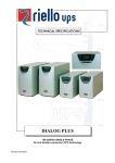
SENTINEL XR TECHNICAL SPECIFICATION SENTINEL XR 3.3- 4- 5- 6 KVA SINGLE PHASE INPUT / SINGLE PHASE OUTPUT On Line Double Conversion (VFI) Technology UPS Series Sentinel XR Date: 14th February 2005 Page 1 of 37 SENTINEL XR Table of contents ..1.. PURPOSE................................................................................................................................................ 3 ..2.. SYSTEM DESCRIPTION.......................................................................................................................... 3 ..3.. APPLICATIONS ...................................................................................................................................... 3 ..4.. FEATURES .............................................................................................................................................. 4 ..5.. REFERENCE STANDARDS ................................................................................................................... 11 > 5.1 Main reference standards........................................................................................................ 11 ..6.. INSTALLATION INSTRUCTIONS ........................................................................................................ 13 > 6.1 Equipment and accessories provided (3300-4000VA)…..……………………………………...13 > 6.2 Equipment and accessories provided (5000-6000VA) ......................................................... 14 > 6.3 Installation and replacement of the battery pack ............................................................... 15 ..7.. BLOCK DIAGRAM OF THE UNIT ....................................................................................................... 17 > 7.1 Operation of the UPS ............................................................................................................... 17 > 7.2 Block diagram of the UPS ........................................................................................................ 17 ..8.. INTERFACING...................................................................................................................................... 19 > 8.1 Expansion slot............................................................................................................................. 20 ..9.. OPTIONS ............................................................................................................................................. 21 > 9.1 Battery box………………………………………………………………………………………………22 > 9.2 Communication cards………………………………………………………………………………..23 > 9.3 Multipass ..................................................................................................................................... 23 > 9.4 Communication software ........................................................................................................ 24 > 9.5 Function of the communication software ……..………….…………………………………….25 ..10.. MIMIC PANEL .................................................................................................................................... 26 > 10.1 Control and signalling panel.................................................................................................. 26 > 10.2 Display panel indications ....................................................................................................... 27 > 10.3 Measurements display area .................................................................................................. 28 > 10.4 Configuration area ................................................................................................................. 29 ..11.. UPS CONFIGURATION ...................................................................................................................... 30 ..12.. VIEWS OF THE UPS ........................................................................................................................... 32 ..13.. TECHNICAL DATA ............................................................................................................................ 34 UPS Series Sentinel XR Date: 14th February 2005 Page 2 of 37 SENTINEL XR 1 - PURPOSE This technical specification describes the SENTINEL XR Uninterruptible Power Supply (UPS) and the relative options. The aim of the specification is to provide: - 2 the technical information for the selection and rating of the uninterruptible power system; the information needed for presettings of the installation premises; the information that the equipment makes available to the user and the connected systems (central monitoring plants, etc.); the list of options available to adapt the equipment to your requirements. - SYSTEM DESCRIPTION SENTINEL XR system is available in models of 3.3-4 -5 – 6 KVA single/single phase and with On Line double conversion (VFI) technology. The load is always powered from the inverter, which supplies a sinusoidal voltage that is filtered and stabilized in voltage, form and frequency; moreover, the input and output filters significantly increase the immunity of the load against mains interference and surges. For its technology, selectable functions (Economy Mode, Smart Active Mode, Back-up unit) and diagnostics (digital display, RS232 and USB interfaces, communication card slot network interface, second serial card, serial duplicator) SENTINEL XR is the best solution for the power supply of sensitive and vital "mission critical" applications and safety devices (electro medical) ensuring maximum reliability. 3 - APPLICATIONS => Personal computers => Small computer networks => Local Area Networks (LAN) => Workstations => Servers => Point Of Sale Systems (POS) => Data centers => Industrial PLCs => Cash registers => Electro medical devices => Emergency devices (lights/alarms) => Telecom devices UPS Series Sentinel XR Date: 14th February 2005 Page 3 of 37 SENTINEL XR 4 - FEATURES Flexibility of installation and use - SENTINEL XR can be installed on the floor (tower version) or in a cabinet (rack version) simply by pulling out and rotating the mimic panel (with the key provided) and adding handles if necessary. - Very low noise (<40dB (A): it is suitable for installation in any environment thanks to PWM digital control ventilation which is dependent on the applied load, the temperature and the use of a high frequency switching inverter (20kHz, value greater than the audibility threshold). Operation Mode The user can select the following functions from the mimic panel: - - - Line Interactive (the Economy Mode): it is used to select Line Interactive (VI) technology to power low-sensitivity loads from the mains in certain periods. The function can be software programmed or manually set from the UPS; Smart Active: if the mains goes out of tolerance, the UPS will power the load from the inverter. When the mains returns within tolerance, the UPS will monitor the mains for some time before switching the load back; Standby OFF (Back-up unit): the UPS can be set to operate only with mains absent (mode suitable for emergency lighting as per EN 50171); Operation from frequency converter (50 or 60Hz); Selectable output voltage (220-230-240V). The software provided allows for a wide range of functions, such as: - Auto restart (automatic restart on return of mains, can be programmed via software); - By-pass on: when the unit is switched off it is automatically set for operation from by-pass and with battery charging; - Shutdown due to minimum load; - Alert end of discharge; - Delay in start up. Maximum reliability for applications - Filtered, stabilized and reliable voltage (On Line double conversion VFI technology in accordance with standard EN 62040-3) with filters to cancel out atmospheric interference: the On Line technology ensures the maximum protection for the connected loads. The double conversion stage filters and stabilizes the input voltage and regenerates it, filtering out mains interference (overvoltages, frequency and voltage variations, etc.). The standard (EN 62040-3) defines this technology as VFI (Voltage and Frequency Independent) because the output voltage and frequency do not depend on the variations and interference on the mains power supply voltage. UPS Series Sentinel XR Date: 14th February 2005 Page 4 of 37 SENTINEL XR High immunity to surges (4KV in accordance with IEC801-5): protections against overvoltages have been provided (VDR). The equipment has been tested by injecting onto the input voltage an overvoltage of the surge type which the standard (IEC 801-5) envisages reaching several kV, with a leading edge of 1.2 microseconds and a duration of approx. 50 microseconds and maximum energy of 300 Joules. High UPS reliability (total microprocessor control) he digital control of the equipment significantly improves the reliability of the system, since it allows significant savings of electronic components (the microprocessor alone performs the functions of a whole electronic control card) and the same card can be used on many devices even of different models, with the subsequent increase in productive volumes and reliability. Low impact on the plant - Load rephasing (UPS input cosfi close to 1) The UPS absorbs from the mains with a power factor close to 1, even if the devices powered have a lower power factor. For example, if the UPS powers a computer device, which typically absorbs current with a power factor of 0.65, the UPS power factor in input will still be close to 1. This allows a significant saving on the mains rephasing banks. - Sinusoidal absorption The UPS absorbs sinusoidal current from the mains. This translates into very low impact of the equipment on the mains power supply and consequently on the other electrical devices powered from the mains. High reliability and availability of the batteries Hot swapping the batteries SENTINEL XR Series allows for the hot swapping of the batteries, that is their replacement while the UPS is on and the load powered. A dedicated battery pack with an integrated protected connection system on the test probe has been implemented for this purpose. When the battery pack needs to be replaced, the lower front panel has to be released to access the battery pack. Pressing the switch located above the pack sends the UPS onto the bypass so that the battery cannot be activated while the pack is being changed. The user can then release the pack and replace it by removing and then plug again the internal battery connector. The operation is carried out in safety thanks to the protected connection system on the test probe and without interrupting the power supply to the load and the UPS. UPS Series Sentinel XR Date: 14th February 2005 Page 5 of 37 SENTINEL XR Automatic battery test A battery test carried out automatically by the UPS provides a periodic check of the efficiency of the batteries, to power supply shutdown. The test is performed in full safety for the critical load and, since it is of short duration, it does not affect the life of the batteries or the back up time. The battery test can also be activated manually from the mimic panel by pressing the “ON” key for some time. - Active control (LRCD: Low Ripple Current Discharge) of the battery current even during the discharge phase, to limit the a/c components on the batteries (ripple at 50 and 100Hz), which are harmful to the life of the batteries. Figure 1. ripple current without and with LRCD High Hold Up Time (>40msec) The batteries are not activated for mains interruptions of less than 40msec. This means that the inverter continues to power the load without needing to absorb energy from the batteries for micro interruptions, which are the most common type of mains interference. Since the life of the batteries depends very much on the number of discharges, this feature really provides optimization of the batteries and consequently reliability of the unit. Protection against deep discharge The end battery discharge voltage increases with low loads. This ensures that deep discharges of the batteries are avoided, as these can affect the average life of the batteries. The test can be programmed: the day and time of the test can be defined from the mimic panel. The test can also be disabled. UPS Series Sentinel XR Date: 14th February 2005 Page 6 of 37 SENTINEL XR Recharge compensated for by temperature Temperature is the main hazard for batteries. The recharge voltage depends on the temperature: the higher the temperature, the lower the recharge voltage will be. This system ensures that the batteries have a high efficiency and reduces ageing. Unlimited expandability of back up time By means of an external battery module which can be supplied with or without battery charger. - Sinusoidal absorption from the mains The UPS absorbs sinusoidal current from the mains. This translates into very low impact of the equipment on the mains power supply and consequently on the other electrical devices powered from the mains. Advanced diagnostics States, measurements and alarms are shown on the digital display. Some commands can also be sent from the front panel. Low consumption Low consumption thanks to the “Economy Mode” and “Smart Active Mode” functions which increase efficiency up to 98%. - Operating modes to reduce consumption In addition to ON LINE operation, other four operating modes are provided. These can be programmed according to the requirements of the user and of the load to be powered: Line Interactive Mode/Smart Active Mode/Standby OFF Mode /Stand-by pass. - Line Interactive (or Economy Mode) Line Interactive (VI) mode allows to power low-sensitivity loads from the mains if it will remain within the tolerance. The mains tolerance can be programmed (3 levels of sensitivity are envisaged: minimum/medium/maximum). The function can be programmed via software or manually set from the UPS. UPS Series Sentinel XR Date: 14th February 2005 Page 7 of 37 SENTINEL XR - Smart Active Mode In Smart Active operation, it is the UPS that automatically selects On Line or Line Interactive operation according to the quality of the mains, by monitoring the number and the frequency of disturbances that occur. The UPS is selected in Line Interactive mode, if the mains goes out of tolerance, the UPS will power the load from the inverter. When the mains returns within tolerance, the UPS will monitor the mains for some time before switching the load back. The UPS is also able to recognize the type of load; in fact, it will not switch to the inverter for mains distortions caused by the insertion of severely distorting loads. - Standby OFF mode (operation as back-up unit) Operation as a back-up unit can be non permanent (Stand By-Off) for the power supply of loads only when the mains fails (emergency lighting). The inverter is normally off, the batteries charging and the UPS actively monitors the input mains. Consumption is obviously greatly reduced in this mode. When the mains fails, the inverter starts up in less than 320 msec (intervention time less than the 500 msec. laid down by the standard) with progressive start up to avoid inrush currents. When the line voltage returns after operation from the battery, the loads are unpowered after a delay (3 sec. to ensure that the mains supply has effectively returned within tolerance): this delay can be programmed via software, from 3 sec. to several hours, to enable the delayed and programmed start up of certain applications (such as main lighting). - Stand by-pass operation The unit is set for operation from by-pass, with the load powered from the mains once the unit is switched off (selectable via software). The battery charger remains on in this operating mode. Flexibility of use - Automatic restart Auto restart (programmable automatic restart on mains return): It is possible to program the automatic restart of the equipment when the mains returns, after it has been switched off for end of back up time following an extended mains failure. This can be programmed via the software supplied with the equipment. - The auto restart can be activated in the following cases: a) On mains return after the UPS has shut down due to full discharge of the batteries; b) On mains return after the UPS has shut down due to automatic shutdown from remote computer system; c) Programmed auto shutdown of the UPS (due to Auto Power Off with low loads). UPS Series Sentinel XR Date: 14th February 2005 Page 8 of 37 SENTINEL XR - Start up from battery (cold start) The UPS can be started up even when there is no mains supply. - Stand by Stand-by operation can be selected: in this mode (useful in periods of inactivity, for example), the inverter is off and the batteries are charging. The stand-by function is automatically activated when the UPS is shut down. - Operation as frequency converter The UPS can be programmed to operate as a frequency converter with batteries, with 50Hz of input and 60 of output or vice versa. This can be selected from the mimic panel. - Frequency autosensing The UPS can be programmed to select the output frequency (50 or 60Hz) automatically, taking the input frequency (50 or 60Hz) as reference. - Compact size The following features make the UPS one of the smallest on the market: . microprocessor control; . IGBT technology; . internal batteries; . ventilation (input at front, output at back: this eliminates the need for space at the sides so the unit can be placed alongside optional devices or other equipment on the premises). - Low noise (<40db(A) It is achieved by: - use of high frequency IGBT technology; - electronically controlled ventilation with PWM technology (Pulse Width Modulation, for improved reliability of the fans) and variable according to the load and the internal temperature; - special design of the magnetic components. Advanced communication Monitoring software including shut down Watch&Save ensures the efficient and intuitive management of the UPS and displays in the form of bar graphs the most important information such as input voltage, applied load, battery capacity, etc. The software is able to give detailed information also in the event of a UPS failure, in support of troubleshooting. UPS Series Sentinel XR Date: 14th February 2005 Page 9 of 37 SENTINEL XR It has been developed with a client/server architecture that makes it flexible and easy to manage, with multilingual support and on-line help. Watch & Save is provided free of charge with the UPSs of the SENTINEL XR range, with SNMP agent included, for the following operating systems: Windows 95, 98, 2000, 2003 Server, Me, Xp, NT4.0, Novell, Mac OS, Mac Osx, Mac Os 9.x, Linux. The software can also be used to program the automatic start up and shutdown of the UPS weekly. The UPS comes with the following hardware interfaces: - RS232 serial port; USB port; isolated contacts interface; slot for the installation of communication card. UPS Series Sentinel XR Date: 14th February 2005 Page 10 of 37 SENTINEL XR 5 - REFERENCE STANDARDS > 5.1 Main reference standards The corporate quality system is certified ISO 9001 (Certificate No CERT-04116-99-AQ-MILSINCERT) which covers all the procedures, operating methods and controls from planning to production activities and sale. This certification is the customer’s guarantee of the following aspects: use of quality materials; accuracy in the production and testing phases; constant attention to the customer’s needs; constant support to the customer. In addition to the corporate certification, the company offers products that are “state of the art” as laid down by observance of the standards listed below. The development of computer technologies obviously requires power supply systems that are able to provide energy that is not only completely accurate but also completely reliable. The standards of the EN50091 series produced by CENELEC cover all aspects of the product: safety, electromagnetic compatibility and performance. To be more precise, the series is subdivided as follows: STANDARDS EN62040-1: Uninterruptible power systems (UPS): general and safety regulations; EN62040-1-1: Uninterruptible power systems (UPS): general and safety regulations for use in areas accessible to the operator; EN60950 : ITE (Information Technology Equipment) safety; EN62040-2: Uninterruptible power systems (UPS): electromagnetic compatibility regulations; EN50081-2: Electromagnetic compatibility (immunity); IEC1000-4-2: Immunity: Electro Static Discharge (ESD); IEC1000-4-3: Immunity: electromagnetic fields; IEC1000-4-4: Immunity: transitory overvoltages (BURST); IEC1000-4-5: Immunity: lightning overvoltage (Surge); UPS Series Sentinel XR Date: 14th February 2005 Page 11 of 37 SENTINEL XR IEC61000-4-11: Low frequency interference; EN50141: Conducted radio interference; EN55022: Radiofrequency interference. EN62040-3 Uninterruptible power systems ( UPS ): regulations for performance and testing methods; EN50171: Centralized power supply for emergencies (CSS); IEC146 (CEI22): Semiconductor electronic converters; IEC529 (CEI70-1): Degree of protection of casing. European Directives 73/23 Low voltage directive requiring obligatory CE marking as from 1/1/97. This directive safeguards aspects with regard to equipment safety. 89/336 Electromagnetic compatibility directive with obligatory CE marking as from 1/1/96. This directive safeguards aspects with regard to immunity to UPS emissions in its environment of use. UPS Series Sentinel XR Date: 14th February 2005 Page 12 of 37 SENTINEL XR 6 - INSTALLATION INSTRUCTIONS > 6.1 Equipment and accessories provided (3300-4000VA) The system is supplied with the following material: UPS Power supply cable (Schuko plug –IEC 16° socket) 2 IEC 10A connection cables IEC 16° loose plug 2 plastic covers (top panels) 2 plastic keys to release display RS232 serial cable User manual + CD-ROM software User's m an u al UPS Series Sentinel XR Date: 14th February 2005 Page 13 of 37 SENTINEL XR ¾ 6.2 Equipment and accessories provided (5000-6000VA) ¾ ¾ ¾ ¾ UPS ¾ 2 plastic keys to release display 2 cable guides ¾ Probes for cables –terminal board connection ¾ ¾ 3 plastic covers (top panels) RS232 serial cable User manual + CD-ROM software Handles Kit User's manual UPS Series Sentinel XR Date: 14th February 2005 Page 14 of 37 SENTINEL XR > 6.3 Installation and replacement of the battery pack TOWER VERSION Once removed from the packaging, the UPS is ready for installation in a tower configuration. All that is needed to complete this configuration is to mount the two plastic covers provided on the upper part of the UPS. The 2 covers have an interlocking system: locate the specific cover mounting holes in the upper part of the UPS and, taking the utmost care, engage the covers by exerting gentle pressure, as shown in the figure at the side. Note: as the covers are exactly the same, either can be mounted indiscriminately on either side (front / back) of the top part of the UPS. RACK VERSION The sequence of operations required to convert the UPS into the rack version is described below. 1 - First remove the 4 feet at the base of the UPS. Put the UPS into a horizontal position and with a small slotted screwdriver carefully lift the pin at the centre of the foot. Once it has been lifted, remove the foot from the base of the UPS. Repeat the same operations for the remaining feet. The exact sequence to follow is shown at the side: 1 2 2 - Once all the feet have been removed, the display mask must then be rotated. Insert the keys provided in the release slots located at the sides of the display mask and exert enough gentle pressure to release the mask from the UPS, as shown in the figure at the side. 3 - Rotate the mask 90° anticlockwise and carefully reengage it in the UPS by inserting it in the housing until a slight click is heard with the mask remaining in position. 4 - Rotate the UPS 90° clockwise. 5 - At this point, with the UPS in a horizontal position, fasten the handles to the sides of the UPS with the specific screws as shown in the figure at the side. (handles and screws are included in the optional handles kit) NOTE: The UPS is compatible for mounting in standard rack cabinets of 600mm x 800mm or more (in width). Support brackets (guides with L-shaped support), available as options, must be used in the rack installation due to the weight of the batteries. It is recommended to install the UPS in the lower part of the rack cabinet for the same reason. UPS Series Sentinel XR Date: 14th February 2005 Page 15 of 37 SENTINEL XR REPLACING THE BATTERY PACK As mentioned in the introduction, the UPS comes with a dedicated battery pack for the easy hot swap replacement of the batteries in full safety thanks to the protected connection system. Below are the basic instruction just for reference, refer to the user manual for detailed instructions 1 - The battery pack is located behind the front panel of the UPS. Hold the panel centrally from the sides and gently pull it outwards as shown in the figure at the side. RNING ! WA RNING ! WA RNING ! WA RNING ! WA 2 - Press the circuit breaker located under the front panel putting it to position “II” as shown in the figure at the side. See the instruction manual before disconnecting the battery connector Press the switch in the position ‘II’ before changing the battery pack 3 - The battery pack is connected to the rest of the UPS via a cable with terminal. Referring to the figure at the side: A A B B 4 - Holding the position described in the previous step, remove the battery pack by pulling it outwards, as shown in the figure at the side. C 5 - Insert the new battery pack in the compartment and slide it until it engages with the UPS. Reconnect the cable with terminal to the connector, put the circuit breaker back to position “I” and close the front panel. Check that the display has returned to normal display mode. UPS Series Sentinel XR Date: 14th February 2005 Page 16 of 37 SENTINEL XR 7 - BLOCK DIAGRAM OF THE UNIT > 7.1 Operation of the UPS Description of the UPS The purpose of a UPS is to ensure a perfect power supply voltage to the equipment connected to it, whether the mains is present or not. Once connected and powered, the UPS generates a sinusoidal alternating voltage with stable amplitude and frequency, regardless of the surges and/or variations present on the mains power supply. While the UPS draws energy from the mains, the batteries are kept charged under the control of the microprocessor. The microprocessor also continuously monitors the amplitude and frequency of the mains voltage, the amplitude and frequency of the voltage generated by the inverter, the applied load, the internal temperature and the state of efficiency of the batteries. The block diagram of the UPS is shown below (see Fig. 5) with a description of its individual components. > 7.2 Block diagram of the UPS Fig. 5 Block diagram UPS Series Sentinel XR Date: 14th February 2005 Page 17 of 37 SENTINEL XR 1) Back-feed protection Back-feed protection (back-feed relay): this is activated if the mains fails, by isolating the UPS from the input socket to prevent voltage returns on the power supply plug. 2) Input fuse This fuse is selective with respect to the input fuse (1): any fault on the rectifier/booster causes this protection device to open, even before the input fuse is triggered. This ensures that the power supply to the application is not interrupted, since the by-pass line remains powered. 3) AC/DC input stage (PFC) With mains present this has the function of converting the alternating mains voltage into direct voltage and monitoring the power factor. If the mains should fail, it raises the battery voltage to a suitable value to power the inverter stage. 4) DC/AC Inverter stage This converts the direct voltage supplied by the rectifier/Booster into alternating voltage. 5) Automatic by-pass The automatic by-pass is a device that automatically switches the UPS output onto the input mains in the event of an overload and/or inverter fault. 6) Inverter switch Provided to switch the load to the by-pass. 7) Battery pack Maintenance-free, lead sealed batteries: they enable installation of the UPS in public environments and ensure the power supply to the load if the mains fails. 8) Battery charger This is a DC-DC converter that converts the output voltage of the rectifier/booster to a suitable level for the bank of batteries to be charged. It is deactivated when the mains fails. 9) Battery protection Protection is by means of fuses. 10) Interface card An RS232 interface, a USB (Universal Serial Bus) interface and a port with isolated contacts are supplied as standard. The RS232 or USB connect automatically when the computer peripheral cable is connected. UPS Series Sentinel XR Date: 14th February 2005 Page 18 of 37 SENTINEL XR 11) Slot for serial card or network card This is an expansion slot that can be used to insert an additional interface: a second RS232 serial card, an SNMP interface for communication on the computer network or an RS232 serial interface duplexer. 12) Display This card provides the user with visual signals (luminous icons and digital display) and acoustic signals (by a buzzer) on the status of the UPS, as well as providing monitoring and control and the personalization of the UPS through easy access to the display menus. 13) Output sockets 1 IEC standard 16 A socket + 2 10 A IEC sockets are available at the back of the unit for connection of the loads 8 - INTERFACING Communication ports The UPS comes with an RS232 and USB serial interface. The serial interface can also be equipped with +/- 12V isolated power supply. The serial interface has a female sub-D 9-pole connector that carries the signals for the interface (fixed baud rate =1200) and three auxiliary optoisolated contacts with the following pin configuration: Pin 7 2 3 8 9 1 5 Name +12V TX RX BL Function Serial transmission line Serial reception line Auxiliary optoisolated contact BW Auxiliary optoisolated contact ALARM Auxiliary optoisolated contact GND Notes Signals end of discharge Signals operation from battery Signals operation from by-pass In addition to the USB and serial port, the UPS also has an expansion slot located at the back, where various types of interfaces can be inserted according to requirements, for example a second serial/USB, mains adaptor, serial multiplier. The signals sent to the slot are shown in the table below. UPS Series Sentinel XR Date: 14th February 2005 Page 19 of 37 SENTINEL XR PIN NAME TYPE 1 2 3 4 5 6 7 8 9 ALARM INIT REMOTE ON REMOTE OFF INVOFF UD UD ID ID ID 10 11 12 13 14 15 16 17 18 19 20 21 22 23 24 25 26 BL BW BY-PASS DCD2 DTR2 +5V +12V RX2 TX2 GND - UD UD UD ID UD PWR PWR ID UD PWR - FUNCTION NOTES Not used Not used Signals UPS fault System initialization Remote UPS start up Not used Not used Remote UPS shutdown Inverter shutdown and passage onto by-pass Signals end of discharge Signals operation from battery Signals operation from by-pass DCD secondary serial line DTR secondary serial line Not used Not used Not used Not used Not used RX secondary serial line TX secondary serial line Not used Not used where UD = digital output, ID = digital input, PWR = power signal. The communication protocol used for the remote control of the UPS via serial port is: PSGPSER. > 8.1 Expansion slot The UPS has an expansion slot enabling the use of various types of interface cards supplied as options according to customer requirements. Various cards can be inserted in the slot, such as a second serial card, a serial multiplier card or a network card for communication between the UPS and the computer network. UPS Series Sentinel XR Date: 14th February 2005 Page 20 of 37 SENTINEL XR 9 - OPTIONS > 9.1 Battery box This is used to extend the UPS back up time. It is contained in a metal box, with the same lines as the UPS and is available without or with battery charger (the latter version enables reduced recharge times). UPS (VA) BATTERY BOX (p/n) Autonomy (min) Battery Dimension (WxDxH) Weight (kg) 3300 6ABA007P09A 6ABA014C09A 6ABA038C09A (ONLY TOWER) 6ABA007P09A 6ABA014C09A 6ABA038C09A (ONLY TOWER) 6ABA007P16A 6ABA012C16A 6ABA007P16A 6ABA012C16A 15 30 70 9 x12V/7Ah 2x(9x12V/7Ah) 9 x12V/38Ah 175x540x455 175x540x455 215x655x630 30 50 145 15 30 60 9 x12V/7Ah 2x(9x12V/7Ah) 9 x12V/38Ah 175x540x455 175x540x455 215x655x630 30 50 145 25 35 20 30 16 x12V/7Ah 16 x12V/12Ah 16 x12V/7Ah 16 x12V/12Ah 175x660x455 175x660x455 175x660x455 175x660x455 65 88 65 88 4000 5000 6000 The battery boxes are designed to be connected in parallel to reach the autonomy required as shown in the following figures UPS BATTERY BOX BATTERY BOX BATTERY BOX BATTERY EXPANSION CABLE UPS Series Sentinel XR BATTERY EXPANSION CABLE Date: 14th February 2005 Page 21 of 37 SENTINEL XR > 9.2 Communication Cards The following communication cards are designed to befitted in the slot located on the rear of the UPS, these can be connected at any time also as retrofit. o Interface Card Netman 102 (SNMP) NETMAN network agent allows the UPS management across a LAN using any of the main network communication protocols TCP/IP, HTTP and network interface (SNMP). o Interface Card MultiCom 302 (MODBUS/JBUS) MultiCom 302 protocol converter may be used to monitor the UPS using the MODBUS/JBUS protocol. It also manages the a second independent RS232 Serial line that can be used to other devices such as NETMAN 101 (box verion). o Interface Card MultiCom 352 (Serial Duplexer) Multicom 352 is a serial duplexer that allows two devices to be connected to a single serial port on a UPS. It can be used where numerous serial connection and multiple polling of UPS are required. o Interface Card Multicom 362 (RS232/USB) Multicom 362 make available a RS232 and USB ports. o Interface Card Multicom 372 (RS232/EPO/Remote Shut Down) Multicom 372 allows to add another RS232 communication port and thought a terminal board Emergency Power OFF (EPO) and the Remote Shut Down (RSD). o Interface Card Multicom 382 (Remote contacts /ESD) Multicom 382 make available through the terminal board the Emergency Power OFF (EPO) , the Remote Shut Down (RSD) and the Alarms (Common alarm, Bypass, Battery working and Battery low. The alarms terminals are suitable to support up to 250 Vac, 3 A. UPS Series Sentinel XR Date: 14th February 2005 Page 22 of 37 SENTINEL XR > 9.3 Multipass The Multipass device has two inputs one from mains and one from UPS, in normal condition the priority supply is the UPS. In case of maintenance the load can be transferred manually on bypass without any solution of continuity. In this condition the UPS can be also removed, if necessary. Multipass it is available for wall mounted or rack version. > 9.4 Communication software MAIN FEATURES 1) Sequential shut-down with defined priority Watch & Save can perform the unmanned shut-down of all the PCs in the network, saving the active work of the most common applications. The user can define individual shut-down procedures and also establish the priority for shutting down critical computers (such as servers). 2) Multiplatform compatibility Watch & Save ensures standard management and monitoring capabilities, using TCP/IP as the communication protocol. This makes it possible to monitor computers with different operating systems from a single console. Thus a UNIX server can be monitored from a PC with Windows 98 and also connect to UPSs located in different geographical areas, by using dedicated networks ( intranet ) or the Internet. 3) Events scheduling Watch & Save can be used to define individual shutdown and restart processes for the powered systems, considerably increasing the safety of the system as well as producing significant energy saving. 4) Management of messages Watch & Save keeps the user constantly informed on the status of the UPS, both locally and by sending messages to the users of the networks; a list of users can also be defined who will receive messages via e-mail, fax and SMS in the event of failures or sudden black outs. 5) Integrated SNMP agent Watch & Save has an integrated SNMP agent for the management of the UPS via SNMP. This agent can send all the information concerning the UPS and generate traps using the standard RFC 1628 MIB. This allows management of the UPS in SNMP-compatible management stations such as HP Open View, Novell Managewise and IBM NetView. UPS Series Sentinel XR Date: 14th February 2005 Page 23 of 37 SENTINEL XR OPERATING SYSTEMS SUPPORTED (WATCH & SAVE professional version) • • • • • Windows 95,98, Me, NT 4.0, Win 2000, Win 2003 Server, XP, Novell Netware 3.x, 4.x, 5.x, IntraNetWare, IBM OS/2 Warp and Server, Mac OS, 9.x, OSX., the most common UNIX operating systems such as: IBM AIX, HP UNIX, SUN OS SPARC, SUN Solaris INTEL and SPARC, SCO Unix and UnixWare, Siemens SINIX, Silicon Graphic IRIX, Compaq True64 UNIX and DEC UNIX, Linux, BSD UNIX and FreeBSD UNIX. > 9.5 Function of the communication software 1) Graphic monitoring of UPS status Watch & Save is a simple but powerful tool for the display and monitoring of the UPSs manufactured by AROS UPS. There are various graphic versions, including Windows, Java, OS/2 and MacOS. 2) Version for MACOS Watch & Save software is the only software for UPS monitoring and shutdown in Macintosh environment with client-server architecture. It allows integration in TCP/IP networks with Windows, Novell, IBM OS/2 and the most common UNIX operating systems. It can support the network agents of the NetMan series for the management of UPSs via network. Multilingual support. 3) Detailed display with all UPS values It provides all the information required for top level diagnostics. 4) UPS block and operating diagrams Watch & Save also displays the UPS in block form, giving the user conceptual information on the operating status. 5) Saving the event history log and graphic display of the main values All events regarding the operating status of the UPS are recorded, so the user can also monitor the state of the input voltage, the load applied to the UPS and the battery back up time. UPS Series Sentinel XR Date: 14th February 2005 Page 24 of 37 SENTINEL XR 6) Alarm notification via e-mail and SMS Watch & Save can be configured to send alarm messages automatically via e-mail or SMS. 7) Programming UPS controls This is used to automate all the actions that are normally carried out by the user: server shutdown and restart, UPS battery test, etc. UPS Series Sentinel XR Date: 14th February 2005 Page 25 of 37 SENTINEL XR 10 - MIMIC PANEL > 10.1 Control and signalling panel View of display 11 9 10 8 1 2 Display LCD 3 4 5 6 7 1 Normal operation 7 Configuration area 2 Operation from mains 8 Service intervention 3 Operation from battery 9 Timer 4 Load on bypass 10 Measurements display 11 Stand-by / fault area 5 Battery level indicator 6 Load level indicator The upper part of the front panel houses a display with yellow/green negative backlighting. The layout of the display, designed to our specifications, can be divided into 3 basic zones: the first, consisting of icons on the left and a red triangle, is dedicated to the UPS status (from the mains, from the battery, from the bypass, normal operation and alarm). The second zone comprises two bar diagrams and numerical indications and the upper part of the middle zone is reserved for measurements. The two bar diagrams show the load and percentage of battery charge, while the numerical indications show the input frequency and voltage, output frequency and voltage, estimated residual back up time (min), estimated battery charge level (%), battery voltage, load UPS Series Sentinel XR Date: 14th February 2005 Page 26 of 37 SENTINEL XR in percentage and the current and temperature of the internal heatsink. Each of these indications has a name and unit of measurement; press the middle key under the display to scroll from one to the other. The same figures can also be used to indicate alarm or locking codes. The last zone on the right consists of the setting area which is entered by pressing down the middle key for some time. The output voltage and frequency and the operating mode can be changed directly from the front panel (without needing to set dip switches). The visual signals can be accompanied by a buzzer which provides an acoustic signal, such as in the following cases: - on start up / shutdown, when the output is synchronized with the input, passage from inverter/bypass and vice versa, in operation from the battery, in overload, in fault / lock. > 10.2 Display panel indications This section describes in detail all the information that can be shown on the LCD display. In order to make it clearer, all the information displayed can be divided into three main groups: ¾ UPS status indicators, ¾ Measurements display area, ¾ Configuration area. UPS status indicators ICON UPS Series Sentinel XR STATUS DESCRIPTION Constant Indicates a fault Flashing The UPS is in stand-by state Constant Indicates regular operation Constant The UPS is operating from the mains Flashing The UPS is operating from the mains, but the output voltage is not synchronized with the mains voltage Constant The UPS is operating from the battery. When it is in this state the UPS emits an acoustic signal (beep) at regular intervals of 4 sec. Flashing End of discharge prealarm. Indicates that the battery back up time is coming to an end. In this condition the UPS emits a beep at regular intervals of 1 sec. Date: 14th February 2005 Page 27 of 37 SENTINEL XR Constant Indicates that the loads connected to the UPS are powered from the by-pass Dynamic If the UPS is operating from the mains, it indicates the battery charge status (%). If the UPS is operating from the battery, it indicates the battery back up time (%) Dynamic Indicates the % of load applied to the UPS with respect to the nominal value Flashing A Service intervention is required (service centre). Contact the Service centre on no. xxxxxxxxx Constant Indicates that the timer is activated (UPS auto-start up and/or auto-shutdown). The timer can be activated/deactivated via the software provided > 10.3 Measurements display area The most important measurements relating to the UPS can be shown in sequence on the display. When the UPS is started up, the display shows the value of the mains voltage. To go on to a different display press the “SEL / SET” button repeatedly until the required measurement is displayed. If a fault / alarm (FAULT) or a lock (LOCK) should occur, the type and corresponding alarm code is automatically shown on the display. Some examples are shown below: GRAPHIC EXAMPLE (1) UPS Series Sentinel XR DESCRIPTION GRAPHIC EXAMPLE (1) DESCRIPTION Mains voltage Total battery voltage Mains frequency Percentage of the applied load Voltage output from the UPS Current absorbed by the load Frequency of the output voltage Temperature of the cooling system for the UPS internal electronics Residual battery back up time Fault / Alarm (2): the corresponding code is displayed Percentage of battery charge Lock (2): the corresponding code is displayed Date: 14th February 2005 Page 28 of 37 SENTINEL XR > 10.4 Configuration area The configuration area groups together the main UPS operating parameters and displays its current status. The parameters contained in this area can be changed directly from the display panel. SETTABLE PARAMETERS: Frequency: Output voltage frequency Frequency Voltage: Mode: Output voltage Voltage UPS operating mode Mode The image at the side is the display zone for the settings (configuration area) showing the three settable parameters. POSSIBLE SETTINGS Frequency: Ù 50 Hz Ù 60 Hz Ù Off (frequency auto-sensing) Voltage: Ù 220 V Ù 230 V Ù 240 V Mode: Ù ON LINE Ù ECO Ù SMART UPS Series Sentinel XR Ù STBYOFF Date: 14th February 2005 Page 29 of 37 SENTINEL XR 11 - UPS CONFIGURATION The following table shows all the possible configurations available to adapt the UPS to the user’s requirements. KEY: Indicates that the configuration can be changed from the display panel as well as by the configuration software provided. = Indicates that the configuration can only be changed via the configuration software provided. = FUNCTION DESCRIPTION Output frequency To select the nominal output frequency Output voltage To select the nominal output voltage Operating mode To select one of the 4 different operating modes Delay before automatic restart Start up delay after the mains returns Automatic shutdown of the Shutdown due UPS in operation to minimum from the battery if load the load is less than 5% Maximum time of Back up time operation from the limit battery Estimated End of remaining back up discharge alert time for the end of discharge alert UPS Series Sentinel XR PREDEFINED POSSIBLE CONFIGURATIONS Auto x x x 50 Hz 60 Hz Auto: automatic sensing from the input frequency 230V x x x x 220V 230V 240V 220 ÷ 240 in 1V steps (only via software) ON LINE x x x x ON LINE ECO SMART ACTIVE STAND-BY OFF 5 sec. x x Disabled 1 ÷ 255 in 1 sec. steps Disabled x x Enabled Disabled x Disabled (full battery discharge) 1 ÷ 65000 in 1 sec. steps Disabled x 3 min. MODE 1 ÷ 255 in 1 min. steps Date: 14th February 2005 Page 30 of 37 SENTINEL XR FUNCTION DESCRIPTION PREDEFINED Battery test Time interval for the automatic battery test 40 hours x x Disabled 1 ÷ 1000 1 hour steps Alarm threshold for maximum load Selects the user overload limit Disabled x x Disabled 0 ÷ 103 in 1% steps Display brightness Acoustic alarm Selects the level of brightness of the LCD display Selects the operating mode of the acoustic alarm POSSIBLE CONFIGURATIONS Maximum Low MODE Minimum ÷ Maximum in 20 steps Normal Low: does not sound for momentary bypass intervention x x ADVANCED FUNCTIONS Selects the allowed input frequency range Input frequency for the passage tolerance onto bypass and for synchronization of the output Selects the allowed voltage Bypass voltage range for the thresholds passage onto bypass Selects the Bypass voltage allowed voltage range for thresholds for ECO operation in ECO mode Selects the Sensitivity of sensitivity of intervention for intervention during ECO operation in ECO mode Power supply of Power supply of the load on the load in bypass with UPS stand-by switched off (stand-by state) Bypass operation Selects the mode of use of the bypass line UPS Series Sentinel XR ± 5% ± 0.25% ± 0.5% ± 0.75% ± 1 ÷ ±10 in 1% steps x x x x Low: 180V High: 264V Low: High: 180 ÷ 200 in 1V steps 250 ÷ 264 in 1V steps Low: 200V High: 253V Low: High: 180 ÷ 220 in 1V steps 240 ÷ 264 in 1V steps Normal x x x Low Normal High Disabled (load NOT powered) x x Disabled (not powered) Enabled (powered) x x Normal Disabled with input / output synchronization Disabled without input / output synchronization Normal x Date: 14th February 2005 Page 31 of 37 SENTINEL XR 12 - VIEWS OF THE UPS UPS 3300 - 4000 VA Release slots Extractable/rotatable display mask Manual bypass switch General switch Cable with terminal Removable front panel Battery pack Front view (front panel off) USB communication port (front panel on) RS232 communication port COMMUNICATION SLOT Expansion slot Cooling fans Input thermal protection IEC 16A Inlet Battery expansion connector IEC 10A outlets IEC 16A outlet Rear view UPS Series Sentinel XR Date: 14th February 2005 Page 32 of 37 SENTINEL XR UPS 5000 - 6000 VA Release slots Rotatable display mask Manual by-pass switch Main switch Battery pack Removable front panel Cable with terminal Cable with terminal Battery pack Front view (front panel off) Fan RS232 communication port (front panel on) Battery expansion connector COMMUNICATION SLOT (expansion) IEC 10A Power share sockets USB communication port Power share sockets heat protection IN / OUT connections box Remote Emergency Power Off. UPS Series Sentinel XR Rear view Date: 14th February 2005 Page 33 of 37 SENTINEL XR 13 - TECHNICAL DATA Environmental condition * Ambient temperature: * Humidity: 0 to 40° C < 90 % Mechanical Data x Dimensions (LxDxH) o o x UPS 3300 - 4000 VA: 175x520x455 mm UPS 5000 - 6000 VA : 175x660x455 mm Weight : 38 Kg (UPS 3300 and 4000 VA), 64 kg (5000 and 6000 VA) UPS Series Sentinel XR Date: 14th February 2005 Page 34 of 37 SENTINEL XR Electrical Characteristics SENTINEL XR 3300 MODELS INPUT Nominal voltage Nominal frequency Accepted range Voltage and frequency variation without with the battery contribution Maximum current (1) Nominal current (2) Power factor Current distortion @ maximum load Recharge time OUTPUT Nominal voltage (8) Frequency (6) Nominal power (3) Nominal power Static variation (4) Dynamic variation (5) Waveform Voltage distortion @ linear load Voltage distortion @ distorting load (3) Inverter Overload Bypass overload Current crest factor UPS Series Sentinel XR SENTINEL XR 5000 SENTINEL XR 6000 [Vac] 220 / 230 / 240 [Hz] 50 - 60 [Vac] 0 ÷ 276 [Vac] Maximum: 276 [Vac] Minimum:164 ÷ 84 (from 100% to 50% of linear load) [Vac] Return to mains-powered operation: 180 [Hz Frequency: 40 to 72 [A] 15 16 [A] 11 12 t 0.98 d 7% d 6% BYPASS Accepted voltage range for switching [Vac] Accepted frequency range for switching Switching time [msec] BATTERY Back-up time at full load No. batteries / V / Ah SENTINEL XR 4000 180 ÷ 264 Frequency selected ±5 % Typical: 2 - Maximum: 4 [min / W] 9 / 12 / 7 high rate discharge [h] [Vac] [VA] [W] 16 / 12 / 7 high rate discharge 4÷6 220 / 230 / 240 ±1.5% 50 or 60 Hz selectable 3300 4000 5000 6000 2300 2400 3500 4200 1.5% d 5% in 20 msec Sinusoidal d 3% d 6% 110 % for 1 min, 150 % for 4 sec. > 150 % for 0,5 sec. 110 % for 2 min, 150 % for 4 sec. > 150 % for 1 sec. t3:1 Date: 14th February 2005 Page 35 of 37 SENTINEL XR SENTINEL XR 3300 MODELS Leakage current to earth AC/AC efficiency Protections Hold-up time Noise level [mA] [msec] SENTINEL XR 4000 SENTINEL XR 5000 SENTINEL XR 6000 d1 90% Excessive battery discharge – Overcurrent – short-circuit – Overvoltage – undervoltage thermal t 40 < 40 dB(A) at 1 mt. (1) @ nominal load, minimum voltage of 164 Vac, battery charging (2) @ nominal load, nominal voltage of 230 Vac, battery charging (3) According to appendix M5 of standard EN50091-1-1 (4) Mains/Battery @ load 0% -100% (5) @ Mains/battery/mains @ resistive load 0% / 100% / 0% (6) If the mains frequency is within ± 5% of the value selected, the UPS is synchronized with the mains. If the frequency is outside the tolerances or operation is battery-powered, the frequency is the selected frequency +0.1% (7) 20 - 25 °C for longer battery life (8) To maintain the output voltage inside the precision range indicated, a recalibration may be necessary after a long period in operation UPS Series Sentinel XR Date: 14th February 2005 Page 36 of 37 SENTINEL XR UPS Series Sentinel XR AROS S.r.l. Via Somalia 20, 20032 Cormano (MI) – Italy Ph. +39 02 66327.1 – Fax +39 02 66327.231 E-mail: th [email protected] Date: 14 February 2005 www.aros.it Page 37 of 37