1
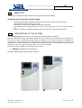
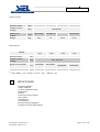
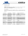
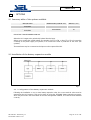
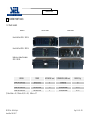
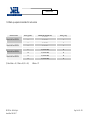
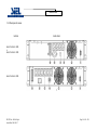
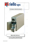
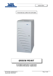
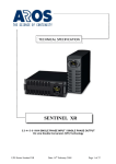
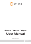
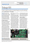
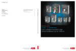
TECHNICAL SPECIFICATIONS
GREEN POINT
1000 - 3000VA SINGLE-PHASE
On line double conversion (VFI) technology
SP122E Rev. 000 Siel S.p.A.
Issued Date: 2005-05-27
Page 1 of 36 + FR
Table of contents
..1.. OBJECTIVE
4
..2.. DESCRIPTION OF THE SYSTEM
4
..3.. APPLICATIONS
5
..4.. CHARACTERISTICS
6
..5.. NORMATIVE REFERENCES
9
5.1 Main reference standards
5.2 Standards relating to systems and installation
..6.. SUPPLIED EQUIPMENTS AND ACCESSORIES
9
10
11
6.1 Tower version
11
6.2 Rack version
12
..7.. BLOCK DIAGRAM OF THE MACHINE
13
7.1 Block diagram of the UPS
13
7.2 Options
13
..8.. INTERFACING
17
8.1 Serial communication port
17
8.2 Communication software
18
8.3 Configuration software
20
..9.. OPTIONS
21
9.1 Summary table of the options available
21
9.2 Installation of the battery expansion module
9.2.1 Configuration of the battery expansion module
21
21
..10.. MIMIC PANEL
22
10.1 LED panel
22
10.2 Description of the mimic panel dial
22
10.3 UPS front views
25
..11.. REAR VIEWS
11.1 Rear panel 1000 - 2000VA Mod.
11.2 Rear panel 3000VA Mod
..12.. TECHNICAL DATA
26
26
27
28
12.1 Tower models
28
12.2 Back-up expansion modules for tower version
28
12.3 Summary data sheets
29
SP122E Rev. 000 Siel S.p.A.
Issued Date: 2005-05-27
Page 2 of 36 + FR
..13.. GREEN POINT RACK
34
13.1 Rack models
34
13.2 Back-up expansion modules for rack version
35
13.3 Rear panels views
36
SP122E Rev. 000 Siel S.p.A.
Issued Date: 2005-05-27
Page 3 of 36 + FR
1
- OBJECTIVE
This technical document is designed to be used by UPS designers and installers.
The objective of this document is to provide or illustrate:
. the technical information required to enable you to choose the correct UPS for your needs
. the information required to set up the system
. information concerning the installation and location of the UPS
. the information the machine displays to the user or to the systems it is connected to (control centres,
etc.)
. the list of the options available to adapt the machine to the user’s particular requirements
2
- DESCRIPTION OF THE SYSTEM
The new Green Point family of UPS has been designed to offer versatility and reliability.
They use ON LINE technology, which means that the AC power for the load is converted to DC and then back to
AC again to ensure a perfectly sinusoidal output, the frequency and voltage of which are established by
microprocessor digital control and are independent of the input power source. This family of UPS has an
automatic by-pass device that switches the load to mains power in the event of overvoltages or any other power
problems to guarantee continuous power supply even in critical conditions.
This family of UPS is available in two versions, rack or tower:
q
Standard: with batteries inside of the UPS
The figures below show the various product versions:
SP122E Rev. 000 Siel S.p.A.
Issued Date: 2005-05-27
Page 4 of 36 + FR
Tower version
MODEL
Nominal power
Output nominal
voltage
Dimensions
HxWxD
Weight
[VA]
Green Point
1000
Green Point
1500
Green Point
2000
Green Point
3000
220/230/240
[Vac]
[mm]
231x158x400
231x158x500
[Kg]
14/8
19
340x192x460
34/14
340x192x460
35/14
Rack version
MODEL
Nominal power
Output nominal
voltage
Dimensions HxWxD
(1)
Weight
(1)
[VA]
Green Point
Green Point
Green Point
Green Point
rack
1000
rack
1500
rack
2200
rack
3000
220 / 230 / 240
[Vac]
[mm]
483x390x88
483x480x88
483x480x176 /
483x480x88
483x480x176 /
483x480x88
[Kg]
16 / 9
21
38 / 13
39 / 14
Nota: 88mm = 2U; 176mm = 4U (2U + 2U);
3
483mm = 19”
- APPLICATIONS
Personal computers
Small IT networks
Local Area Networks (LAN)
Workstations
Servers
Point of sale (POS) systems
Data centres
Industrial PLCs
Cash registers
Electrical medical equipment
Emergency devices (lights/alarms)
SP122E Rev. 000 Siel S.p.A.
Issued Date: 2005-05-27
Page 5 of 36 + FR
4
- CHARACTERISTICS
Filtered, stable and reliable voltage (On Line double conversion VFI technology in accordance with regulation
IEC62040-3) with filters for suppressing atmospheric disturbances.
The on line technology provides the maximum protection for the loads the system is connected to. The double
conversion stage filters and stabilises the input voltage, and reproduces it free of any mains disturbance
(overvoltages, variations in frequency and voltage, etc.).
The IEC62040-3 standard defines this technology as VFI (Voltage and Frequency Independent) because the
output voltage and frequency are completely independent of any variation or disturbance to the voltage of the
mains power supply.
High level of reliability, versatile and easy to maintain
− High level of reliability of the UPS (total microprocessor control):
The digital control of the system dramatically improves its overall reliability, because it means that a
reduced number of electronic components are required (the microprocessor alone handles all the
functions of an entire electronic control board). This electronic control board can be used on a whole
number of different machines, even those belonging to different ranges, thereby increasing the
productivity and reliability of the system.
−
High overloads: the UPS can feed loads up to 150% also in absence of the main.
− Programmed shutdown timer (programmable via software):
This function (programmable via software) allows you to program the timer to switch the system on and
off in a completely automatic fashion.
-
Stand by:
The Stand-by function may also be selected. In this mode (useful, for example, when the system is
being stored), the inverter is switched off and the batteries are fully charged. When the UPS is switched
off, the stand-by function is automatically activated.
-
Frequency converter function:
The UPS can be programmed to function as a frequency converter using batteries, from an input
frequency of 50Hz to an output frequency of 60Hz, or vice versa.
Selectable via softwarel.
-
Frequency auto-selecting
The UPS can be programmed to automatically select the output frequency (50 or 60Hz), using the input
frequency as its reference (50 or 60Hz).
-
Battery start-up (cold start)
The UPS can be switched on even if there is no mains power supply.
SP122E Rev. 000 Siel S.p.A.
Issued Date: 2005-05-27
Page 6 of 36 + FR
-
Autorestart (programmable automatic restart when the mains power supply returns): In the event of a
prolonged absence in the mains power supply, the system will automatically restart when the mains
power supply returns after it has shutdown on reaching the end of its back-up time. This can be
programmed using the software provided with the machine.
-
Net Phone and computer protections avoid overvoltage, on RJ11 and RJ45 connectors.
-
Restore input protection:
The UPS mounts one input standard protection ( restorable ), against overloads or short circuits.
Low consumption
− Low impact on the mains power supply (sinusoidal absorption):
The UPS absorbs a sinusoidal current from the mains power supply. This means that the system has a
very low impact on the mains power supply network and, as a consequence, on the other electrical
devices that are connected to it.
−
Load power factor correction (UPS input factor close to 1):
The UPS absorbs power from the mains power supply with a power factor close to 1, even if the systems
supplied by the UPS have a power factor inferior to this. For example, if the UPS supplies a piece of IT
equipment with a power factor of 0.65, the UPS input power factor will nevertheless still be close to 1,
ensuring that the mains power supply power factor correction banks are not overtaxed.
Battery optimisation:
− High level of battery reliability (automatic battery test):
The UPS automatically carries out a battery test allowing the system to periodically check the efficiency of
the batteries, in order to prevent faults occurring to them. The test does not in any way compromise the
power supply to the users connected to the UPS and, given the short duration (seconds), does not affect
the life or the back-up time of the batteries either.
− Wide Input Voltage tollerances (from 110V to 300V) without battery participations.
-
Unlimited back-up expandability:
through external battery modules supplied with a UPS which includes an improved and upgraded
battery charger.
SP122E Rev. 000 Siel S.p.A.
Issued Date: 2005-05-27
Page 7 of 36 + FR
Compact dimensions
Thanks to the following characteristics, the UPS is one of the smallest on the market:
. microprocessor control
. IGBT technology
. internal batteries
. ventilation (frontal input, rear output: this eliminates the need to keep a lateral space free and allows
the machine to be placed next to other options or systems )
Reduced noise (<40db(A))
due to:
- use of high frequency IGBT technology
- innovations in the design of the magnetic parts
Advanced Communication
-
Selection via software of the operating parameters
Through the supplied software is possible to personalize the UPS operating parameters depending on
own necessities (see page 19).
-
Monitoring and shutdown software included
GreenShield provides an efficient and intuitive system for controlling the UPS, displaying all the most
important information, such as input voltage, applied load, battery capacity, etc. with a series of bar
charts.
The software is able to provide detailed information even if the machine has malfunctioned, enabling
you to find out why the fault has occurred.
It has been developed using a client/server architecture that renders it flexible and easy to use, with
multilingual support and on line help.
With UPSs in the GREEN POINT range, GreenShield is provided free of charge with an SNMP agent, for
Windows 95, 98, 2000, Windows 2003 Server, Me, Xp, NT4.0, Novell, Mac OS, Mac Osx, Mac Os 9.x,
Linux operating systems.
The software also allows you to programme the automatic start-up and shutdown of your system on a
weekly basis.
The UPS also contains the following hardware interfaces:
-
RS232 serial port
signals interface
slot for the installation of a mains adapter
SP122E Rev. 000 Siel S.p.A.
Issued Date: 2005-05-27
Page 8 of 36 + FR
5
- STANDARDS
5.1 Main standards
The company quality system has been certified as conforming to ISO 9001 (Certificate ITALCERT No.
005/03). This covers all of the procedures, operating methods, and controls from the design stage right up
to the production and sale of the machine.
This certification guarantees the following aspects for our customers:
. the use of quality materials
. rigorous standards in production and testing
. receptiveness and openness to our customers
. constant support of all our customers
As well as being covered by this company certification, the company produces “state of the art” products,
as dictated by the requirements of the standards quoted below.
The advances that have taken place in Information Technology systems mean that the power supply
systems used to power them must be able to provide an absolutely precise, and even more importantly,
absolutely reliable source of power. The standards produced by IEC/CENELEC in the IEC/EN62040
series cover all aspects of the product: safety, electromagnetic compatibility and performance.
EN62040-1:
Uninterruptible power supply systems (UPS): general provisions and safety provisions
EN62040-1-1:
Uninterruptible power supply systems (UPS): general provisions and safety provisions used in
areas accessible to the operator
EN60950 (CEI74-2):
ITE (Information Technology Equipment) safety
EN62040-2:
Uninterruptible power supply systems (UPS): electromagnetic compatibility provisions.
EN50081-2:
Electromagnetic compatibility (immunity)
IEC1000-4-2:
Immunity: Electro Static Discharge (ESD)
IEC1000-4-3:
Immunity: electromagnetic fields
IEC1000-4-4:
Immunity: transient overvoltages (BURST)
IEC1000-4-5:
Immunity: current surges (Surge)
IEC61000-4-11:
Low frequency disturbances
EN50141:
EN55022:
Induced radio interference
Radio frequency disturbance
ENV62040-3
Uninterruptible power supply systems (UPS): performance provisions and test procedures.
SP122E Rev. 000 Siel S.p.A.
Issued Date: 2005-05-27
Page 9 of 36 + FR
IEC146 (CEI22):
Semiconductor electronic converters
IEC529 (CEI70-1):
Degree of protection of casings
European Directives
73/23
Low voltage directive enforcing the obligatory CE marking from 1/1/97. This directive concerns all safety
issues associated with the equipment.
89/336
Electromagnetic compatibility directive enforcing the obligatory CE marking from 1/1/96. This directive
concerns all issues of immunity and emissions relating to the UPS at its place of installation.
WEEE/ROHS: environments directives that supply indications and norms about elimination of the
electronic and electrical material (Waste of Electronic and Electric Equipments) and limitations of use of
injurious substances (Restriction on use Of Hazardous Substances).
5.2 Standards relating to systems and installation
The above product regulations refer specifically to uninterruptible power supply systems. It is these
regulations that manufacturers of uninterruptible power supply systems are obliged to adhere to.
However, with regard to the electrical system, the installer must refer to other standards.
These standards are:
− Standard CEI 64-8 (HD384/IEC60364)
for electrical systems in general
− Standard CEI 64-8 variant 2:
for installation in hospital environments
− Standard CEI 11-20:
for systems with UPS machines connected to category I or II networks
− Standard CEI 17-13 (EN60439-1)
concerning control equipment
− Standard EN50272-2
for battery installation (shortly to be replaced by the European Standard EN50272-2).
− Standard CEI 20:
for electrical cables
SP122E Rev. 000 Siel S.p.A.
Issued Date: 2005-05-27
Page 10 of 36 + FR
6
- SUPPLIED EQUIPMENTS AND ACCESSORIES
6.1 Tower version
The tower-version UPS is supplied together the following equipments:
q
q
q
UPS
q
RS232 serial cable
IEC 10A (o 16A) Power cord
q
IEC 16A Power cord set (only for model
3000VA)
2 IEC 10A connection cables
q
User manual + CD-ROM with software
User's
manual
SP122E Rev. 000 Siel S.p.A.
Issued Date: 2005-05-27
Page 11 of 36 + FR
GREEN POINT
6.2 Rack version
The rack-version UPS is supplied together the following equipments:
q
UPS
IEC 10A (or 16A) power supply cable
q
q
2 IEC-IEC 10A connection cables
IEC 16A loose plug
(only for 300)
q
ONLY FOR GREEN POINT RACK 220 / 300:
q
RS232 serial cable
q
q
q
Battery expansion cable
handles
q
q
BATTERY BOX
Fuse (25A GL)
CD-ROM software + User manual
User's
manual
SP122E Rev. 000 Siel S.p.A.
Issued Date: 2005-05-27
Page 12 of 36 + FR
GREEN POINT
7
- BLOCK DIAGRAM
7.1 Block diagram of the UPS
The block diagram of the UPS is as follows.
Fig.2 Block diagram
7.2 Options
Isolating transformer
Back-up extension
Net Adapter
USB Converter
LEGEND:
1) Restore Input protection
2) Input EMI filter + back-feed protection:
Input and output filters for electromagnetic disturbances.
Back-feed protection: intervenes if the mains power supply fails, isolating the UPS from the input socket
to prevent the mains power supply from returning. This protection is required to prevent voltage from
returning to the line, which could put the operator at risk when carrying out maintenance work.
SP122E Rev. 000 Siel S.p.A.
Issued Date: 2005-05-27
Page 13 of 36 + FR
GREEN POINT
3) Rectifier/booster block protection fuse.
This fuse is dependent on the status of the input fuse (1): a fault occurring to the rectifier/booster will
open this protection before the input fuse intervenes, ensuring that the power supply to the user is not
interrupted, as the by-pass line remains powered.
4) Rectifier/Booster:
When the mains power supply is present, this converts the mains alternating current into a direct
current, controlling the power factor. If the mains power supply fails, it elevates the battery voltage to an
appropriate level to power the inverter stage.
5) Inverter:
Converts the direct current into alternating current
6) Automatic by-pass:
Device for switching from the inverter to the mains, and vice versa, without interrupting the power
supply. Intervenes if overloads or faults occur.
7) Output switch:
To isolate the UPS when carrying out maintenance work.
8) Output EMI filter:
Output filter for protecting the load against electromagnetic disturbances.
9) Maintenance-free sealed lead batteries:
Allow the UPS to be installed in public places and to power the load when the mains power supply fails.
10) Battery expansion (from 1000 to 3000VA models):
Allows you to prolong the back-up time.
11) Battery charger:
This is a DC-DC converter that converts the rectifier/booster output voltage to the level required to
recharge the batteries. It is deactivated when the mains power supply fails.
12) Battery protection:
Fuse
13) Intelligent slot for the auxiliary communication boards connectivity (accessory cards).
14) Net – Tel protection (on RJ11 and RJ45) to protectt phone and computer nets from
overvoltage.
15) RS232 interface for supervision and shut down software
SP122E Rev. 000 Siel S.p.A.
Issued Date: 2005-05-27
Page 14 of 36 + FR
GREEN POINT
16) Mimic panel:
This is the board that provides the user with all the visual (LED, LCD) and acoustic (buzzer) signals
pertaining to the status of the UPS. This board also allows you to control and send commands to the
UPS.
Operating modes
"NORMAL" mode
This is the operating mode of the UPS where the power is drawn from the mains power supply. The
UPS output is switched onto the inverter (refer to block diagram) and the batteries are kept fully
charged.
Automatic "BY PASS" mode
The UPS enters to this operating mode in the following situations:
a) Immediately after the UPS is switched on, when the mains power supply is present, the UPS output is
switched onto the by-pass line and the load is powered by the mains power supply.
This allows you to exceed the applied load in-rush current without tripping the fuses to the inverter.
During this stage, the microprocessor ensures that the inverter output is brought in phase with the
mains power supply.
b) When the inverter is permanently overloaded.
The inverter continues to power the load even when there is a temporary overload. If this condition
persists, the inverter protection is tripped and the UPS is switched onto the by-pass.
c) When the voltage produced by the inverter exceeds allowed tolerance limits
d) When the inverter malfunctions.
"BATTERY" mode
The UPS operates in this mode when the mains power supply fails (micro-interruptions or black-outs).
During this mode, the buzzer emits an intermittent beep:
a) during the autonomy functioning mode
b) when the back-up time limit has been reached
Approximately 2 mins from the end of the back-up time the yellow "battery discharged" LED will light up
(if the management software has been installed, the programmed shutdown of the I. T. applications will
begin at this point).
“Error conditions”
The UPS is designed to function reliably and to automatically guarantee the protection of the applied
load. However, particular operating conditions may exist which the operator should be aware of to
ensure that the UPS provides the highest level of performance.
SP122E Rev. 000 Siel S.p.A.
Issued Date: 2005-05-27
Page 15 of 36 + FR
GREEN POINT
“Overload”
An overload occurs where the applied load requires a level of power higher than that for which the UPS
has been designed.
This situation is indicated by the (red) overload LED on the load LED bar and by the sound of the
buzzer.
To rectify this situation, you need to turn the UPS off (OFF button), reduce the applied load, and switch
the UPS back on again (ON button).
“Mains out of tolerance”
The UPS is designed to function with a wide range of input voltages. This ensures that the batteries do
not intervene too often, thus increasing the back-up time should a real blackout occur.
The microprocessor continuously checks the input voltage and frequency to guarantee functioning and
switches the load onto the by-pass within a wide tolerance range
“Overtemperature”
If the internal temperature exceeds acceptable limits, the UPS will protect itself by shutting down. This
situation is indicated by the "Stop/Stand-by" LED and the continuous sound of the buzzer.
“Batteries depleted”
The microprocessor carries out a periodic battery efficiency test. If the batteries fail the test, the red
"Batteries need substituting" (efficiency < 60%) LED is lit.
In this case, the UPS batteries should be replaced.
SP122E Rev. 000 Siel S.p.A.
Issued Date: 2005-05-27
Page 16 of 36 + FR
GREEN POINT
8
- INTERFACING
8.1 Serial communication port
The UPS has the following communication ports (see UPS views):
RS232 serial port
-
COMMUNICATION SLOTS: expansion slots for additional interface cards
RS232 serial port
The RS232 serial port allows the connection of a PC (COM port) by means of a pin-to-pin serial cable
(provided(1)).
RS232 CONNECTOR
6 7 8 9
1 2 3 4 5
PIN
No.
1
2
3
4
5
6
7
8
9
(1)
SIGNAL
Contact closed: UPS failure/Bypass/Alarm (2)
TXD
RXD/SD (remote shutdown) (3)
GND
+12Vdc interface power input
PNP Signal
Contact closed: battery low pre-alarm (2)
Contact closed: battery mode (2)
If a different cable is used, it should be of the pin-to-pin type with a max. length of 3
metres.
(2)
(3)
Optoisolated contact max. +35Vdc / 15mA.
SD: With UPS in operation from battery, the UPS will perform a complete shutdown when
+5~15Vdc is applied (between PIN 3 and PIN 5) for at least 20 seconds.
Communication Slot
All UPS come with an expansion slot for optional communication boards so that the unit is compatible with the
main communication options.
Some examples:
•
Serial port duplexer
•
Ethernet network agent with TCP/IP, HTTP and SNMP protocols
•
RS232 + RS485 port with JBUS / MODBUS protocol
•
For more details on the options available, visit the manufacturer’s web site.
SP122E Rev. 000 Siel S.p.A.
Issued Date: 2005-05-27
Page 17 of 36 + FR
GREEN POINT
8.2 Communication software
MAIN CHARACTERISTICS
1) Sequential and prioritised shutdown:
GreenShield allows you to shutdown the network without having to switch off each PC individually,
and saves the work that was being done regardless of the application that was being used. The
user may define his or her own shutdown procedure and may also prioritise the shutdown of critical
components within the system (such as servers).
2) Multiplatform compatibility:
GreenShield provides you with a standard control and monitoring capability, as it uses the TCP/IP
communication protocol.
This allows you to monitor computers that use different operating systems from a single console.
For example, not only could you monitor a UNIX server from a PC with Windows 98, you could also
connect yourself to UPS systems situated in different locations by using either a dedicated network
(intranet) or the Internet.
3) Events scheduling:
GreenShield allows you to define your own shutdown/switch off and on again procedures for the
systems that are connected to the UPS. Not only does this noticeably increase the degree of
security of the system it also allows you to make significant energy savings.
4) Message management:
GreenShield keeps the user constantly informed on the status of the UPS, whether locally or by
sending messages to users connected to the network. It is also possible to create a list of the
people who will receive messages by e-mail, fax and SMS should a fault or a sudden blackout
occur.
5) Integrated SNMP agent:
GreenShield contains an integrated SNMP agent for managing the UPS via SNMP.
This agent is able to send all the information pertaining to the UPS and is capable of generating
traps using the RFC 1628 MIB standard.
This allows you to control the UPS using SNMP compatible workstations such as HP Open View,
Novell Managewise and IBM NetView.
OPERATING SYSTEMS SUPPPORTED
•
•
•
•
•
Windows 95,98, Me, NT 4.0, Win 2000, Win 2003 Server, XP.
Novell Netware 3.x, 4.x, 5.x, IntraNetWare
IBM OS/2 Warp and Server,
Mac OS, 9.X, OSX
The most commonly available UNIX systems such as:
IBM AIX, HP UNIX, SUN OS SPARC, SUN Solaris INTEL and SPARC, SCO Unix and UnixWare,
Siemens SINIX, Silicon Graphic IRIX, Compaq True64 UNIX and DEC UNIX, Linux, BSD UNIX and
FreeBSD UNIX
SP122E Rev. 000 Siel S.p.A.
Issued Date: 2005-05-27
Page 18 of 36 + FR
GREEN POINT
GREENSHIELD SOFTWARE FUNCTIONS
1)
Graphical monitoring of the UPS status
GreenShield is the easy to use yet powerful program that allows you to monitor and control the UPS
systems.
There are various graphical versions including Windows, Java, OS/2 and MacOS.
2)
MACOS version
The GreenShield software is the only UPS control and shutdown software available for the Macintosh
that has a client-server architecture.
Allows you to access the Windows, Novell, IBM OS/2 and the most commonly available UNIX operating
systems when using a TCP/IP network.
It also allows you to support NetMan series network agents to control the UPS via a network and,
furthermore, comes with multilingual support.
3)
Detailed display of all the ups data
GreenShield provides all the data required to make an accurate and speedy diagnosis of UPS
operation.
4)
Block diagram and operating diagram of a UPS
GreenShield also displays a block diagram of the UPS, thus providing the user with conceptual
information as to the status of the system.
5)
Automatic saving of the events log and graphical display of the most important
values
All of the events pertaining to operation of the UPS are saved and recorded, thus allowing the user to
also control the input voltage, the applied load and the remaining back-up time of the batteries.
6)
Alarm notification via e-mail and SMS
It is possible to configure GreenShield to automatically notify of an alarm via an e-mail or SMS
message.
7)
Programming the UPS commands
Also allows you to program all the commands that are normally carried out by the user so that these are
performed automatically, for example: shutting down and switching the server back on, UPS battery
test, etc.
SP122E Rev. 000 Siel S.p.A.
Issued Date: 2005-05-27
Page 19 of 36 + FR
GREEN POINT
8.3 Configuration software
Configuration Software
UPSTools software allows the user to configure the UPS and provides a full view of the system
parameters and status through the RS232 serial port.
Refer to the paragraph UPS Configuration for a list of the possible configurations available.
UPS Configuration
The following table lists all the possible configurations available so as to best adapt the UPS to user
requirements. The configuration may be modified only by using the configuration software provided
(UPSTools).
FUNCTION
DESCRIPTION
PREDEFINED
POSSIBLE CONFIGURATIONS
•
•
Disabled
Enabled
Automatic Restart
Automatic restart when
mains power returns
Enabled.
Battery low alarm
Remaining battery
charge level setting for
the battery low alarm
3 min.
1 - 99 in steps of 1 minute
•
•
•
50Hz
60Hz
Auto (depending on the UPS input
frequency it will operate at 50 or 60
Hz)
220 Vac
230 Vac
240 Vac
Output frequency
Allows the user to select
the output frequency.
50Hz
Output voltage
Allows the user to select
the output voltage
230 Vac
Bypass voltage
threshold
Selects the voltage
range accepted for
switching over to bypass
Low: 180V
High: 264V
Low:180 ÷ 200 in steps of 1V
High: 250 ÷ 264 in steps of 1V
Battery capacity
Allow the user to set the
capacity of battery
Standard:
7.2Ah
ER:
65Ah
The user must set the capacity of battery if
the actual capacity is different from the
default value.
SP122E Rev. 000 Siel S.p.A.
Issued Date: 2005-05-27
•
•
•
Page 20 of 36 + FR
GREEN POINT
9
- OPTIONS
9.1 Summary table of the options available
DESCRIPTION
Isolating transformer module for
1000/1500
Isolating transformer module for
2000/3000
DIMENSIONS (HxWxD mm)
WEIGHT ( KG )
480x158x340
22
480x158x340
30
ISOLATING TRANSFORMER MODULE:
Allows the UPS output to be galvanically isolated from the input.
Allows you to modify the neutral regime (for example, from TT to TN, or from TT to IT) to increase the
continuity of the power supply (IT systems) or to increase the level of protection of the users (TN
systems).
The transformer may be connected to the input or to the output of the UPS.
9.2 Installation of the battery expansion module
Fig.5
9.2.1. Configuration of the battery expansion module
Following the installation or one or more battery expansion units, the correct total Ah value must be
entered into the UPS memory. This may be done by using the “EXPAND” battery expansion program,
which may be found in the same folder as the UPS management software, once this has been installed
correctly.
SP122E Rev. 000 Siel S.p.A.
Issued Date: 2005-05-27
Page 21 of 36 + FR
GREEN POINT
10 . MIMIC PANEL
10.1. LED panel
The LED panel enables the user to check the UPS status and operating mode. It indicates in which mode the
UPS is working (on mains, on by-pass, on battery); it shows the load applied; the battery charge level and
warns about error conditions.
Vista pannello indicazioni led versione tower e rack
!
7
100
6
1
<= TOWER VERSION
75
5
50
2
RACK VERSION =>
3
4
5
6
4
25
LOAD
BAT
1
2
3
7
1
Load level indicator
5
Battery failure indicator
2
Battery level indicator
6
Load powered by bypass indicator
3
Mains mode indicator
7
“Fault/Stand-by” indicator
4
Battery mode indicator / Battery low indicator
10.2 Description of the mimic panel dial
Led indicator panel
This chapter gives a detailed description of all LED indicator panel.
ICON
SP122E Rev. 000 Siel S.p.A.
Issued Date: 2005-05-27
STATUS
DESCRIPTION
Red / Steady
Indicates an fault
Red /
Flashing
The UPS is in stand-by mode
Green / Steady
The UPS is operating on mains power
Page 22 of 36 + FR
GREEN POINT
Green /
Flashing
The UPS is operating off the bypass
The voltage input is out of the accepted range
§
§
Green / Steady
The UPS is operating in battery mode and will beep at regular
intervals.
Green /
Flashing
When operating off battery power, the UPS signals that it is about
to switch off due to end of discharge. In this state, it beeps at
regular intervals of 1 sec. (see Tab. 1)
Red / Steady
Indicates battery failure
Yellow / Steady
The loads connected to the UPS are powered by the bypass
Green / Active
Represents the estimated percentage of battery charge by 5
LEDs
(see table 2)
Hold the ON button down for at least 10 seconds to show the
input voltage value (see table 3)
Green – Red /
Active
Indicates the % of load applied to the UPS in relation to the
nominal value. the last icon indicates overload (see table 4)
Tab. 1: battery status
Battery status
LED - battery working -
Normal
?
Low
??
?
??
LED with steady light on
LED with flashing light on (1 flash per second)
Tab. 2: battery level
Battery level
Battery LED bar
1
2
3
4
0%~20%
?
20%~40%
?
?
40%~60%
?
?
?
60%~80%
?
?
?
?
80%~100%
?
?
?
?
SP122E Rev. 000 Siel S.p.A.
Issued Date: 2005-05-27
5
?
Page 23 of 36 + FR
GREEN POINT
Tab. 3: input voltage
Input Voltage
190V~200V
200V~230V
230V~250V
250V~260V
>260V
Battery LED bar
1
2
3
4
5
?
?
?
?
?
?
?
?
?
?
?
?
?
?
?
100
!
Tab. 4: load level
Load level
Load LED bar
25
50
75
0~5%
?
??
5~25%
?
25%~50%
?
?
50%~75%
?
?
?
75%~102%
?
?
?
?
>102%
?
?
?
?
?
LED on with steady light
LED with flashing light on (1 flash per second)
Overloads on the UPS
The following table shows how the UPS reacts when mains and battery overloads occur and indicates the time
that the UPS will remain powered.
LOAD POWER TIMES
LOAD POWER TIME
(off mains)
(off battery)
102% < Load ≤ 109%
Switches to bypass after 30 min
Shutdown after 30 min (if battery
back up time allows)
110% <= Load ≤ 130%
Switches to bypass after 30 sec
Shutdown after 30 sec
130% < Load ≤ 150%
Switches to bypass after 10 sec
Shutdown after 10 sec
Load > 150%
Switches to bypass after 0.5 sec
Shutdown after 0.5 sec
OVERLOAD LEVEL
SP122E Rev. 000 Siel S.p.A.
Issued Date: 2005-05-27
Page 24 of 36 + FR
GREEN POINT
10.3 UPS front views
Models: 1000-1500VA
1
2
3
Models: 2000-3000VA
1
2
3
1.
2.
3.
LED mimic panel
ON button
OFF button
SP122E Rev. 000 Siel S.p.A.
Issued Date: 2005-05-27
Page 25 of 36 + FR
GREEN POINT
11 . REAR VIEWS
11.1 Rear Panel Mod. 1000 ÷2000 VA
Green Point 1000 / 1500
1
7
1
7
8
2
2
3
3
6
6
4
4
5
5
Green Point 2000
1
7
8
2
6
4
3
5
1.
2.
3.
4.
RS232 serial communication port
Cooling fans
Telephone/modem protection/net or intranet
Input thermal protection
SP122E Rev. 000 Siel S.p.A.
Issued Date: 2005-05-27
5.
6.
7.
8.
IEC mains input plug
IEC output sockets (max 10A)
Communication expansion slot
Battery expansion connector
Page 26 of 36 + FR
GREEN POINT
11.2 Rear panel Mod. 3000 VA
Green Point 3000
7
1
7
8
8
9
2
2
6
10
6
3
3
4
5
5
1.
2.
3.
4.
5.
RS232 serial communication port
Cooling fans
Telephone/modem protection/net or intranet
Input thermal protection
IEC mains input plug
SP122E Rev. 000 Siel S.p.A.
Issued Date: 2005-05-27
6. IEC output sockets (max 10A)
7. Communication expansion slot
8. Battery expansion connector
9. IEC 16A output socket
10 Output socket fuse boxes
Page 27 of 36 + FR
GREEN POINT
12 TECHNICAL DATA
12.1 Tower models
MODEL
GP1000
GP1500
GP2000
GP3000
POWER
1000VA/700W
1500VA/1050W
2000VA/1400W
3000VA/2100W
BACK-UP ( min )
8’ (internal batteries)
8’ (internal batteries)
13’ (internal batteries)
8’ (internal batteries)
DIMENSIONS
WEIGHT
(HxWxD mm)
231x158x400
231x158x500
340x192x460
340x192x460
(Kg)
14
19
34
35
12.2 Back-up expansion modules for tower version
MODEL to bind
GP 1000VA
GP 1500VA
GP 2000VA
GP 3000VA
SP122E Rev. 000 Siel S.p.A.
Issued Date: 2005-05-27
BACK-UP (min)
17
DIMENSIONS (HxWxD mm)
231x158x455
WEIGHT (Kg)
13
28
231x158x455
17
15
231x158x455
15
23
231x158x455
21
30
340x158x485
28
42
340x158x485
40
15
340x158x485
28
23
340x158x485
40
Page 28 of 36 + FR
GREEN POINT
12.3 Summary data sheets
MODELS
1000VA
1500VA
2000VA
3000VA
INPUT
Input phases
1
Rated Voltage
220 / 230 / 240 V singlephase
Maximum input voltage
before battery intervenes
Minimum input voltage
before battery intervenes
(applied load 100%)
300 V singlephase
(110 ± 5) V singlephase (load 0% ÷ 60%)
(160±5) V singlephase (load 80% ÷ 100 %)
Standard 50Hz
(settable through software to 50Hz, 60Hz or self-teaching)
Rated frequency
Input frequency tolerance
Maximum current
± 5Hz
5A
7.2 A
10 A
14.4 A
Thermal switch
12 A
Thermal switch
16 A
In-rush current
<In
Power factor
>0.97
Current distorsion (THDi)
<3%
Input protection
Thermal switch
7A
Thermal switch
10 A
“Hold up” time (interr. To
mains power supplies
before batteries
intervenes)
<40ms
BY-PASS
Maximum voltage
acceptable for switching
to mains power
Minimum voltage
acceptable for switching
to mains power supply
264V singlephase
180V singlephase
BATTERIES
Back-up in min
8’
8’
13’
8’
N° Batteries
3
4
8
8
Battery rated voltage
36 V
48 V
96 V
96 V
SP122E Rev. 000 Siel S.p.A.
Issued Date: 2005-05-27
Page 29 of 36 + FR
GREEN POINT
Type of batteries
7Ah Sealed lead maintenance-free
Battery configuration
In series
Type of recharge
At two voltage levels
Recharge current
0,9A
Recharge time
4h
Intervention time (loss of
mains power supply)
Zero
Battery ripple current
< 0,01C
Battery voltage stability
(batteries fully charged)
< 0.7 %
Battery protection
Fuse
OUTPUT
Rated voltage
220/230/240 V selectable
Wave form
Sinewave
Frequency
(50/60 ±0,2) Hz selectable
Frequency converter
function
Current peak factor (from
EN62040-3 regulation)
Yes (with batteries)
3:1
Rated output (VA)
1000 VA
1500 VA
2000 VA
3000 VA
Rated output (W)
700 W
1050 W
1400 W
2100 W
Static variation
Dinamic variation (with
load impact from 0 to
100%)
Output frequency
variation with mains
absent
± 1.5 %
=5%
Same as the mains, for variations between ± 5 %
Frequency variation
velocity (Hz/sec.)
1 Hz/s
Voltage reset after
dynamic variation
< 20 ms
Voltage distortion (linear
load)
<2%
Voltage distortion (nonlinear load)
<6%
OVERLOAD TIMES
SP122E Rev. 000 Siel S.p.A.
Issued Date: 2005-05-27
Page 30 of 36 + FR
GREEN POINT
INVERTER OVERLOAD WITH MAINS ON LINE
100%<Load<110%
30 ‘
110%<Load<130%
Load 150%
30 ‘’
10 ‘’
VARIOUS
AC/AC efficiency (double
conversion operation)
Maximum permanent
operating temperature
Ambient operating
temperature
Recommended operating
temperature (for
batteries)
90 %
40°C
40°C
20/25°C
Humidity
<95 % without condensation
Protections
Excessive battery discharge – overcurrent – short circuit –
overvoltage – undervoltage - heat
Compliance with safety
regulations
EN62040 -1-1
Directives 73/23/EEC and 93/68/EEC
EMC compliance
EN62040 -2 cl. B, directive 89/336/EEC
Immunity to sudden
current surges
Noise
6kV 300J following IEC61000-4-5
<40 dB (A) at 1 mt
DIMENSIONS
Height (mm)
Width (mm)
231
158
231
158
340
192
340
192
Depth (mm)
400
500
460
460
14
19
34
35
Weight in Kg (with
standard back-up
integrated batteries)
Mechanical
characteristics
Shielded metal cabinet with an applied plastic frontal display
Level of protection
Resistance to vibrations
(G)
Power dissipated with
load present (W)
IP215
<2G
77
115
140
Colour
RAL 7035
Input differential current
1 mA
210
OUTPUT PROTECTION FIGURES (RECOMMENDED VALUES FOR SELECTIVITY)
Normal fuses (GI)
Normal circuit-breakers
(curve C)
Ultra-rapid fuses
(UR-URG)
Cable input
SP122E Rev. 000 Siel S.p.A.
Issued Date: 2005-05-27
In (Rated current)/7
In (Rated current)/7
In (Rated current)/2
Rear
Page 31 of 36 + FR
GREEN POINT
Input connection
Output connection
IEC socket
4 IEC sockets + 1 Rs 232 + 1
protezione Net Tel + slot
6 prese IEC + 1 Rs 232 + 1
protezione Net Tel + slot
Cooling
Forced ventilation
Maximum installation
altitude
1000m
Power derating
10% every 1000m above 1000m above seal level
SP122E Rev. 000 Siel S.p.A.
Issued Date: 2005-05-27
Page 32 of 36 + FR
GREEN POINT
13 . GREEN POINT RACK
13.1 Rack models
MODELS
FRONT VIEWS
REAR VIEWS
Green Point Rack 1000 ÷ 1500 VA
Green Point Rack 2200 ÷ 3000 VA
Battery box included for models
2200 ÷ 3000 VA
MODELS
Green Point Rack 1000
Green Point Rack 1500
Green Point Rack 2200
Green Point Rack 3000
(*) Note: 88mm = 2U; 176mm = 4U (2U + 2U);
SP122E Rev. 000 Siel S.p.A.
Issued Date: 2005-05-27
POWER
1000 VA/700 W
1500 VA/1050 W
2200 VA/1540 W
3000 VA/2100 W
483mm = 19”
AUTONOMY (min)
(*)DIMENSIONS (HWD mm)
WEIGHT (Kg)
8
8
12
8
88x483x390
88x483x480
(88+88)x483x480
(88+88)x483x480
16
21
11 + 27
12 +27
Page 33 of 36 + FR
GREEN POINT
13.2 Back-up expansion modules for rack version
MODEL to bind
Green Point Rack 1000VA
Green Point Rack 1500VA
Green Point Rack 2200VA
Green Point Rack 3000VA
BACK-UP (min)
17
30
15
27
27
38
15
30
(*) Note: 88mm = 2U; 176mm = 4U (2U + 2U);
SP122E Rev. 000 Siel S.p.A.
Issued Date: 2005-05-27
DIMENSIONS (HxWxD mm)
2Ux19’’x390
2Ux19’’x390
2Ux19’’x480
2Ux19’’x480
2 x (2Ux19’’x480)
3 x (2Ux19’’x480)
2 x (2Ux19’’x480)
3 x (2Ux19’’x480)
WEIGHT (Kg)
12
19
15
25
54
81
54
81
483mm = 19”
Page 34 of 36 + FR
GREEN POINT
13.3 Rear panels views
MODELS
REAR VIEWS
Green Point rack 1000
e
Green Point rack 1500
Green Point rack 2200
SP122E Rev. 000 Siel S.p.A.
Issued Date: 2005-05-27
Page 35 of 36 + FR
GREEN POINT
Green Point rack 3000
Battery Box
1 - RS232 serial communication port
2 - Cooling fans
SP122E Rev. 000 Siel S.p.A.
Issued Date: 2005-05-27
3 - IEC output sockets (max 10A)
4 - Input thermal protection
5 - IEC mains input plug
6 - Battery expansion connector
7 - IEC output sockets 16A
Page 36 of 36 + FR