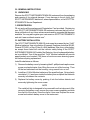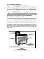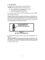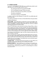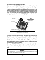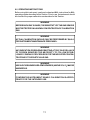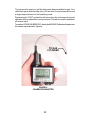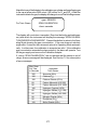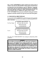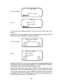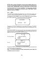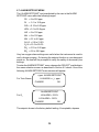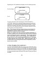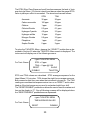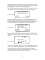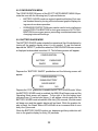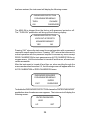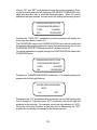
1
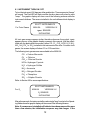
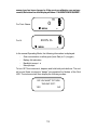
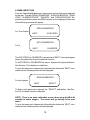
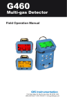
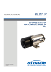
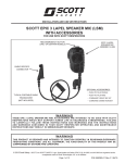
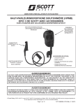
MINI-SA PORTABLE
GAS DETECTION
INSTRUMENT
1
INTRINSICALLY SAFE GAS
LEVEL DETECTOR
C
R
39NO
US
CERTIFIED BY UNDERWRITERS LABORATORIES INC.
ONLY AS TO INTRINSIC SAFETY
FOR USE IN HAZARDOUS LOCATIONS
CLASS I, DIV, 1, GROUPS A, B, C, & D.
CERTIFIED TO CANADIAN CSA STANDARD C22.2 NO. 157-92
WARNING:
SUBSTITUTION OF COMPONENTS MAY IMPAIR INTRINSIC SAFETY.
USE ONLY WITH APPROVED BATTERIES.
TEMPERATURE CODE T3C.
CAUTION:
FOR SAFETY REASONS, THIS EQUIPMENT MUST BE
OPERATED AND SERVICED BY QUALIFIED PERSONNEL ONLY.
READ AND UNDERSTAND MANUAL BEFORE OPERATING AND SERVICING
CHANGE BATTERIES IN NON-HAZARDOUS AREA
SCOTT INSTRUMENTS
EXTON, PA 19341
2
SCOTT INSTRUMENTS
MINI-SA PORTABLE GAS
DETECTION INSTRUMENT
Contents
1.0 INTRODUCTION ................................................................. 4
2.0 OPERATIONAL ENVIRONMENT ........................................ 4
3.0 GENERAL INSTRUCTIONS ............................................... 5
3.1
UNPACKING .......................................................... 5
3.2
REGISTRATION ..................................................... 5
3.3
BATTERY INSTALLATION ..................................... 5
4.0 INSTRUMENT DESCRIPTION ............................................ 6
4.1
ALARM LEGENDS ................................................. 7
4.2
AUDIBLE ALARMS ................................................ 8
4.3
VIBRATION ALARM ............................................... 9
4.4
ALARM LED LIGHTS ............................................. 9
4.5
STATUS LIGHT ...................................................... 9
5.0 SWITCH FUNCTIONS AND DISPLAYS ........................... 10
6.0 OPERATING INSTRUCTIONS ........................................... 11
6.1
INSTRUMENT TURN ON / OFF ............................ 12
6.2
MENU SELECTION .............................................. 14
6.3
ZERO CALIBRATION MENU ................................ 17
6.4
SPAN CALIBRATION MENU ................................ 18
6.5
SENSOR REPLACEMENT MESSAGE ................. 22
6.6
PEAK / HOLD MENU ............................................ 23
6.6.1 PEAK ............................................................. 23
6.6.2 HOLD ............................................................. 25
6.7
ALARM SETPOINT MENU ................................... 26
6.8
TWA / STEL MENU .............................................. 29
6.9
CONFIGURATION MENU ..................................... 32
6.9.1 BATTERY SAVER MODE ............................... 32
6.9.2 PASSWORD PROTECTION .......................... 33
7.0 ERROR MESSAGES ........................................................ 37
8.0 CALIBRATION GASES .................................................... 38
9.0 SPECIFICATIONS ............................................................ 39
3
SCOTT INSTRUMENTS MINI-SA PORTABLE GAS DETECTOR
1.0 INTRODUCTION
The SCOTT INSTRUMENTS MINI-SA Portable Gas Detector is a self contained
instrument designed to detect and provide audible, visual, and tactile indication
of the presence of oxygen or toxic gas in the air. The toxic gas concentration is
monitored and shown in the graphic display in parts per million (ppm) of the
atmosphere. The oxygen concentration is shown in the graphic display as a
percent (%). When the gas level exceeds the preset level, alarms actuate
including a pulsing audible alarm tone, flashing LED, and a vibration alarm.
The alarm functions for toxic gases include a Time Weighted Average (TWA)
Alarm and a Short Term Exposure Level (STEL) Alarm.
Other features include AUTO CALIBRATION and self diagnostic capabilities, a HOLD function that displays the lowest level detected, and user
adjustable high and low ALARM SETPOINTS. A battery life indicator constantly monitors remaining battery capacity and a backlight provides visibility in low light situations.
Additional features include a PASSWORD PROTECT menu and a BATTERY SAVER mode.
2.0 OPERATIONAL ENVIRONMENT
The SCOTT INSTRUMENTS MINI-SA Portable Gas Detector is designed to
be “INTRINSICALLY SAFE” suitable for operation in Class I, Division 1, Groups
A, B, C & D Hazardous Locations.
4
3.0 GENERAL INSTRUCTIONS
3.1 UNPACKING
Remove the SCOTT INSTRUMENTS MINI-SA instrument from its packaging
and examine it for external damage. If any damage is found, notify your
SCOTT INSTRUMENTS distributor, sales representative, or the SCOTT INSTRUMENTS Service Department.
3.2 REGISTRATION
Fill out and mail the postage paid Registration Card provided. Registering
your SCOTT INSTRUMENTS MINI-SA instrument assures that you will receive notification of any future enhancements and/or upgrades that become
available. You may also register your instrument on SCOTT INSTRUMENTS
web site “www.scottinstruments.com”.
3.3 BATTERY INSTALLATION
The SCOTT INSTRUMENTS MINI-SA instrument is powered by two “AAA”
Alkaline batteries. Use only alkaline (Eveready Energizer Industrial EN 92,
Duracell PC2400, or Ray-O-Vac AL-AAA) batteries. Use of any other batteries except those listed will void the intrinsic safety listing of the SCOTT
INSTRUMENTS MINI-SA Portable Gas Detector. Use of rechargeable batteries is prohibited. Two of the specified “AAA” Alkaline batteries will provide
approximately one hundred (100) hours of continuous non-alarming operation before requiring replacement.
Install the batteries as follows:
1) Remove the battery cover by loosening the #1-phillips-head captive cover
screw counterclockwise, then lifting the cover out of the housing. Then
lift the two batteries from the housing, using a small coin or tool.
2) Install two (2) AAA Alkaline batteries of the specified type. Note polarity
orientation (+/-) as shown inside the battery box and push the batteries
securely in between the contacts.
3) Replace the battery cover by pushing it into the bottom detents and
secure by tightening the cover screw.
NOTE
The metal belt clip is designed to be removed from the instrument. After
removing the battery cover, remove the cover screw completely and slide
the clip out of the cover. Store the clip for future use. Replace the cover
screw and reattach battery cover to the instrument.
5
4.0 INSTRUMENT DESCRIPTION
THE SCOTT INSTRUMENTS MINI-SA INSTRUMENT is designed for use as
a personal monitor. The MINI-SA is equipped with a snap mounting clip for
ease of use. A break-away neck strap and rubber boot are also available.
All operations of the instrument are controlled by two push-button actuators
which are large enough to accommodate use with gloved hands. In each
menu screen, “PROMPTS” over each push-button define their use.
The SCOTT INSTRUMENTS MINI-SA INSTRUMENT case is constructed of
high impact resistant, flame retardant plastic. The push-button actuators
and the graphic display overlay are UV and chemical resistant.
The Graphic Liquid Crystal Display (LCD) provides continuous readings of
gas concentration as well as battery life remaining and other information.
Alarm conditions are signaled by an alarm legend on the graphic display, an
audible tone, a flashing light, and an internal vibration. Audible tones for
certain alarms can be suspended for thirty (30) second intervals while others will continue until the unit is reset in an atmosphere that corresponds to
the preset safe values. Alarms can also be configured to be latching or
nonlatching. Latching alarms operate until acknowledged. Nonlatching
alarms clear automatically when the detected gas is on the safe side of the
alarm setting.
SENSOR
BATTERY
MENU
GRAPHIC
LED
(GREEN OR RED
DEPENDING
PUSHBUTTONS
FIGURE 1
MINI-SA INSTRUMENT
(w/ H2S Sensor shown for reference)
6
4.1 ALARM LEGENDS
The following alarm legends appear in the graphic display:
“ALARM” flashing legend indicates one of the following:
a) Gas concentration which exceeds the preset level
b) A Time Weighted Average (TWA) Alarm
c) A Short Term Exposure Level (STEL) Alarm.
For toxic gas, the ppm, TWA, or STEL level detected and the “ALARM”
legend will flash alternately.
A graphic battery level indicator appears continuously on the display screen.
The indicator shows battery capacity as ten (10) lines inside a picture of a
battery. Each line represents approximately 10% of battery time remaining.
The battery level indicator flashes when the batteries are low. This will occur
when approximately 10% of battery life remains.
EACH LINE REPRESENTS
APPROXIMATELY 10%
OF BATTERY TIME REMAINING
FIGURE 2
BATTERY LEVEL INDICATOR
An exhausted battery alarm will occur after the last bar disappears. See
Figure 2.
“HOLD ACTIVATED” flashing legend indicates that the HOLD feature has
been selected. The instrument will display the highest reading of a toxic gas
or the lowest oxygen reading. This reading will continue to be displayed until
the HOLD function is reset.
7
4.2 AUDIBLE ALARMS
The SCOTT INSTRUMENTS MINI-SA has an audible alarm which is activated when any of the following conditions occurs:
-
The preset gas alarm level is exceeded (ALARM)
-
The Time Weighted Average (TWA) is exceeded
-
The Short Term Exposure Limit (STEL) is exceeded
-
The battery is exhausted
-
The sensor is missing or incompatible
In addition, each time the instrument is turned ON, the audible alarm will
pulse three times.
The following describes the function of the Audible Alarm during the alarm
conditions listed above:
GAS ALARM – The Audible Alarm sounds when a gas concentration is detected that exceeds the chosen alarm level, or when a TWA or STEL alarm
value is exceeded. A repetitive pulsing tone will occur at one (1) second
intervals while the alarm condition exists.
In the LATCHING alarm mode, selected in the Alarm Setpoint Menu, after an
alarm condition has cleared, the alarm indication will continue until the alarm
is acknowledged by depressing a pushbutton. In the NON-LATCHING alarm
mode, all alarm indications clear when the alarm condition clears. In either
mode, the instrument gives an “all clear” signal with three audible beeps,
three flashes of the Red Alarm Light, and three vibration pulses when the
alarm indication is cleared.
When an Audible Alarm sounds, depressing either pushbutton on the instrument will silence the Audible Alarm for thirty (30) seconds. If the original
alarm condition still exists after the thirty (30) second silence period, the
Audible Alarm will sound again. The Audible Alarm can be silenced repeatedly by depressing a pushbutton.
LOW BATTERY – An Audible Alarm tone will pulse once every fifteen (15)
seconds to indicate when less than 10% of battery life remains.
MISSING SENSOR – The Audible Alarm for a missing or incompatible sensor is identical to the pulsing one (1) second tone that occurs during an
ALARM condition. Depressing a pushbutton to acknowledge the condition
turns the unit OFF.
8
4.3 VIBRATION ALARM
An internal vibrating motor activates whenever the Audible Alarm sounds. The
Vibration Alarm operates as a secondary alarm feature in high noise environments where the audible alarm may be difficult to hear.
The Vibration Alarm is reset the same as the Audible Alarm as described in
Section 4.2.
The Vibration Alarm will also pulse briefly whenever the MINI-SA instrument
is turned ON or OFF.
WARNING
THE VIBRATION ALARM DOES NOT FUNCTION FOR THE LOW BATTERY INDICATION.
4.4 ALARM LIGHT
The SCOTT INSTRUMENTS MINI-SA instrument contains a Red Light Alarm
LED (Light Emitting Diode) which flashes whenever any Alarm Condition occurs. It will continue to flash when the Audible Alarm is silenced and will flash
as long as the alarm condition is present. In the LATCHING alarm mode,
selected in the Alarm Setpoint Menu, after an alarm condition has cleared,
the alarm indication will continue until the alarm is acknowledged by depressing a pushbutton. In the NON-LATCHING alarm mode, all alarm indications clear when the alarm condition clears. In either mode, the instrument
gives an “all clear” signal with three audible beeps, three flashes of the Red
Alarm Light, and three vibration pulses when the alarm indication is cleared.
4.5 STATUS LIGHT
The instrument also has a Green Status LED that flashes periodically, indicating continuing instrument operation.
9
5.0 SWITCH FUNCTIONS AND DISPLAYS
All operations on the MINI-SA Portable Detector are controlled by two pushbuttons located on the bottom of the unit. The operations vary depending on
the operating mode and the graphic display appearing above the two switches.
The unit sounds a brief audible “beep” whenever either pushbutton is depressed while the instrument is on. Whenever the instrument is turned ON or
OFF, three successive audible tones will sound and the Red Alarm LED will
flash. The Green Status LED will flash once every fifteen (15) seconds during
instrument operation. When in the BATTERY SAVER mode, the Green Status LED flash rate increases to once every five (5) seconds.
LED
(GREEN OR RED
DEPENDING
SENSOR
GRAPHIC
PUSHBUTTONS (2)
FIGURE 3
COMPONENT LOCATIONS
When the unit is in the operating mode, depressing the Display Backlight
Pushbutton will illuminate the graphic display for fifteen (15) seconds. A light
bulb icon for the Backlight is located above the pushbutton on the operating mode screen. Depressing the button again extinguishes the Backlight.
The Backlight is sustained ON or OFF while the MENU operations are in
progress, except for calibration. In an alarm condition, the Backlight flashes
for the duration of the alarm indication.
When in the BATTERY SAVER mode, the instrument graphic display will be
blank. Depressing either pushbutton will turn on the graphic display. The
display remains on for thirty (30) seconds after the last pushbutton operation.
WARNING
USE OF THE DISPLAY BACKLIGHT FOR EXTENDED PERIODS OF TIME
WILL REDUCE BATTERY SERVICE LIFE.
10
6.0 OPERATING INSTRUCTIONS
Before using this instrument, read and understand ALL instructions for ALL
operating modes described in this Section. Prior to use, the instrument should
be checked for proper calibration as described in this Section.
WARNING
BEFORE EACH DAY’S USAGE, THE SENSITIVITY OF THE GAS SENSOR
MUST BE TESTED ON A KNOWN CONCENTRATION OF CALIBRATION
GAS.
WARNING
ACTUAL CALIBRATION SHOULD ONLY BE PERFORMED BY QUALIFIED INSTRUMENT MAINTENANCE PERSONNEL.
WARNING
ANY INDICATION OR READING DENOTING A TOXIC GAS OR A LACK
OF OXYGEN SIGNIFIES THE NECESSITY TO FOLLOW ESTABLISHED COMPANY PROCEDURES FOR THE INDICATED CONCENTRATIONS OF THE PARTICULAR GAS.
WARNING
USE IN OXYGEN ENRICHED ATMOSPHERES (ABOVE 25% O2) MAY BE
HAZARDOUS.
WARNING
CONFIRM THE INSTRUMENT’S BASIC CALIBRATION IS APPROPRIATE FOR THE INTENDED USE.
11
6.1 INSTRUMENT TURN ON / OFF
To turn the instrument ON, depress either pushbutton. Three successive “beeps”
will sound. The Red LED will flash and the vibration alarm will pulse for each
“beep.” The graphic display will show one of the following screens while the
instrument initializes. The sensor installed in the unit defines which display is
shown:
SCOTT INSTRUMENTS
For Toxic Gases
MINI-SA
VERSION X.X
<gas> SENSOR
INITIALIZING
All toxic gas screens appear similar, therefore wherever the symbol <gas>
appears on any of the graphic display screens in this manual, it will be substituted with the applicable toxic sensor (either CO, Cl2, ClO2, HCN, H2S, NH3,
NO2, NH3, PH3 or SO2) installed in the instrument at the time. For some toxic
gases, the screen display will show 0.0 or 0.00 resolution.
The following toxic gas sensors are available in the MINI-SA:
CO = Carbon Monoxide
Cl2
= Chlorine
ClO2 = Chlorine Dioxide
HCN = Hydrogen Cyanide
H2S = Hydrogen Sulfide
NH3 = Ammonia
NO2 = Nitrogen Dioxide
PH3 = Phosphine
SO2 = Sulphur Dioxide
Refer to Section 9.0 for sensor specifications.
SCOTT INSTRUMENTS
For O2
MINI-SA
VERSION X.X
O2 SENSOR
INITIALIZING
After a few seconds, the instrument will sound a single “beep” and go to the Operating Mode where the graphic display will show one of the following screens:
Note: If a new sensor is installed or if batteries have been removed for more
than a few minutes, the initialization sequence may take longer. If the
12
sensor type has been changed or if the previous calibration was not successful, the bottom line of the display will show “CALIBRATION REQUIRED”.
ppm
0
For Toxic Gases
<gas>
MENU
20.9% O2
For O2
MENU
In the normal Operating Mode, the following information is displayed:
-
Gas concentration in either ppm (toxic Gas) or % (oxygen)
-
Battery life indication
-
Backlight prompt
-
Menu prompt
To turn OFF the instrument, depress and hold both push-buttons. The unit
will sound three successive “beeps” accompanied by flashes of the Red
LED. The instrument will then display the following screen:
DO YOU WANT TO TURN
THE UNIT OFF?
YES
NO
13
6.2 MENU SELECTION
From the Operating Mode screen, there are six menus that can be selected
by the user. They are “ZERO CALIBRATION,” “SPAN CALIBRATION,” “PEAK/
HOLD,” “ALARM SETPOINT,” “TWA/STEL,” and “CONFIGURATION.” Depress the pushbutton below the MENU prompt on the display and then one
of the following screens will appear:
ZERO CALIBRATION
For Toxic Gases
NEXT
AUTO ZERO
AUTO CALIBRATION
For O2
NEXT
CALIBRATE
The AUTO ZERO or CALIBRATE command and “NEXT” command appear
above the pushbutton that activates that function.
To AUTO ZERO or CALIBRATE the sensor, depress the right pushbutton.
See Section 6.3 for details on calibration.
To go to the next menu, depress the left pushbutton below the “NEXT” command and the following screen will be displayed:
SPAN CALIBRATION
For toxic gases
NEXT
SELECT
To Span a toxic gas sensor, depress the “SELECT” pushbutton. See Section 6.4 for details on span calibration.
NOTE: There is no span calibration screen when using the Mini-Sa
portable to detect oxygen. The screen will go directly to the next
menu.
To go to the next menu, depress the left pushbutton below the “NEXT” command and the following screen will be displayed:
14
PEAK / HOLD
NEXT
SELECT
To go to the PEAK/HOLD menu, depress the “SELECT” pushbutton.
To go to the next menu, depress the left pushbutton below the “NEXT” command and one of the following screens will be displayed:
<gas> ALARM SETPOINT
For Toxic Gases
NEXT
SELECT
O2 ALARM SETPOINT
For O2
NEXT
SELECT
To go to the ALARM SETPOINT menu, depress the “SELECT” pushbutton.
To go to the next menu, depress the left pushbutton below the “NEXT” command and one of the following screens will be displayed:
<gas> TWA/STEL
For Toxic Gases
NEXT
SELECT
NOTE: There is no TWA/STEL menu displayed when an instrument is
used for oxygen detection.
To go to the TWA/STEL menu, depress the “SELECT” pushbutton. See
Section 6.8 for details.
To go to the next menu, depress the left pushbutton below the “NEXT” command and the following screen will be displayed:
15
CONFIGURATION
NEXT
SELECT
To go to the CONFIGURATION menu, press the “SELECT” pushbutton.
To go to the next menu, depress the left pushbutton below the “NEXT” command and the ZERO CALIBRATION for toxic gas or AUTO CALIBRATION for
oxygen screen will again be displayed.
The MINI-SA will scroll repeatedly through these Menus each time the “NEXT”
pushbutton is depressed. Each time either pushbutton is depressed, the unit
will sound a single “beep”.
If no menu action is taken for fifteen (15) seconds while one of the menus is
displayed, the instrument will automatically return to the operating mode,
signified by a single “beep”.
16
6.3 ZERO CALIBRATION MENU
The MINI-SA instrument can be Auto Zeroed at any time. An Auto Zero should
only be performed in an area known to be free of toxic gas or any known
cross sensitive materials. See Section 8.0 for SCOTT INSTRUMENTS supplied calibration gas cylinders. When performing an auto-zero with an oxygen unit, be sure the area contains 20.9% oxygen.
To perform Zero Calibration of the sensor as described in Section 6.2, depress the “AUTO ZERO” pushbutton when the ZERO CALIBRATION menu
screen is displayed.
The instrument will display one of the following screens while it calibrates the
appropriate sensor.
<gas> SENSOR
For Toxic Gases
ZERO CALIBRATION
2
O2 SENSOR
For O2
ZERO CALIBRATION
2
The instrument display will count down 2 seconds while the sensor is zeroed. After a successful “ZERO CALIBRATION”, the instrument will sound a
“beep” and automatically go back into the Operating Mode.
If, during the “ZERO CALIBRATION”, the unit detects that the sensor is out of
range, an error message will be displayed. See Section 7.0 for a description
of error messages.
17
6.4 SPAN CALIBRATION MENU FOR TOXIC GAS ONLY
Note: The MINI-SA software requires that an “AUTO ZERO” be performed as
described in Section 6.3 before the instrument will allow a “SPAN CALIBRATION”. Failure to do so will display the following screen when attempting a
“SPAN CALIBRATION” of the instrument:
AUTO ZERO REQUIRED
BEFORE
SPAN CALIBRATION
ACKNOWLEDGE
Depress both pushbuttons simultaneously to acknowledge this message
and “AUTO ZERO” the instrument per Section 6.3 to procede.
The MINI-SA instrument can be calibrated with span gas supplied by SCOTT
INSTRUMENTS or with a calibration gas supply certified to a concentration
within the following ranges:
CO = 25 to 120 ppm
Cl2
= 5 ppm only Cl2
ClO2 = 5 ppm only Cl2
HCN = 2.0 to 25.0
H2S = 10 to 110 ppm
NH3 = 10 to 40 ppm
NO2 = 2.0 to 15.0 ppm
PH3 = 0.5 to 4.5 ppm
SO2 = 2.0 to 18.0 ppm
See Section 8.0 for SCOTT INSTRUMENTS supplied calibration gas
cylinders.
To perform “SPAN CALIBRATION” of the sensor, depress the “SELECT”
pushbutton when the “SPAN CALIBRATION” screen is displayed as described in Section 6.2. The instrument will display the one of the following
screens:
<gas> SENSOR
For Toxic Gases
SPAN CALIBRATION
USING <_> ppm <CALGAS>
CHANGE
OK
18
Calibration cylinders supplied by SCOTT INSTRUMENTS contain 25 PPM
H2S or 50 PPM CO. To use another certified concentration, depress the left
pushbutton below the “CHANGE” command. The one of the following screens
will be displayed:
<gas> SENSOR
For Toxic Gases
SPAN CALIBRATION
GAS = <_> ppm <CALGAS>
UP
DOWN
Factory preset span calibration gas values:
CO = 50 ppm
Cl2
= 5.0 ppm
ClO2 = 5.0 ppm Cl2
HCN = 10.0 ppm
H2S = 25 ppm
NH3 = 25 ppm
NO2 = 5.0 ppm
PH3 = 1.0 ppm
SO2 = 10 ppm
If you select the “UP” pushbutton, for example, one of the following screens
will display with the number value flashing:
<gas> SENSOR
For Toxic Gases
SPAN CALIBRATION
GAS = <_> ppm <CALGAS>
UP
SET
When the desired value has been reached depress the “SET” pushbutton
and the “CHANGE/OK” screen will appear again. Select the “OK” pushbutton
and one of the following screens will display:
<gas> SENSOR
For Toxic Gases
SPAN CALIBRATION
INJECT <_> ppm <CALGAS>
EXIT
19
This screen will remain on until the instrument detects calibration gas. If no
calibration gas is detected after thirty (30) seconds, the instrument will sound
a single beep and return to the operating mode.
Depressing the “EXIT” pushbutton will also return the instrument to normal
operation with no calibration having occurred. The last successful calibration
will remain valid.
To continue “SPAN CALIBRATION”, attach the 40014936 Calibration Adapter over
the sensor cap as shown in Figure 4.
TO GAS
CYLINDER
FIGURE 4
CALIBRATION ADAPTER
20
Attach the hose of the Adapter to the calibration gas cylinder and begin flowing gas
to the cap at a flow rate of 500 cc/min. (300 cc/min. for Cl2 and ClO2). When the
instrument detects the gas, the display will change to one of the following screens:
<gas> SENSOR
For Toxic Gases
SPAN CALIBRATION
<time> seconds
The display will count down <seconds> (See chart below for applicable sensor) after which the instrument will display the message “SPAN CALIBRATION PASSED ACKNOWLEDGE”. Press either button to return to the Operating Mode showing the gas concentration. If the user does not acknowledge within 2 minutes, the instrument returns to Operating Mode automatically. In either case, the calibration is accepted as valid. If the calibration
gas concentration exceeds the alarm setpoint, the alarm will operate. Turn
off the gas supply and remove the Calibration Adapter.
If, during “SPAN CALIBRATION”, the unit detects that the sensor is out of
range, an error message will be displayed. See Section 7.0 for a description
of error messages.
Max. Span
Cal Time
in Seconds
300
180
180
60
90
180
60
60
90
90
120
Applicable
Toxic Sensor
Ammonia (NH 3 )
Chlorine(Cl 2 )
Chlorine Dioxide (ClO 2 )
Carbon Monoxide (CO 500)
Carbon Monoxide (CO 1000)
Hydrogen Cyanide (HCN)
Hydrogen Sulfide (H 2 S 100)
Hydrogen Sulfide (H 2 S 500)
Nitrogen Dioxide (NO 2 )
Phosphine (PH 3 )
Sulfur Dioxide (SO2 )
21
Note: SCOTT INSTRUMENTS supplies Teflon®-lined tubing with all
chlorine and ammonia calibration kits. Sticky gases such as chlorine
and ammonia require this tubing be used for calibration. Using tubing of another type may inhibit the automatic calibration of a MINI-SA
and lead to improper readings or a false failed sensor message. All
other calibration kits are supplied with Tygon (R-3603) Tubing.
SCOTT INSTRUMENTS also recommends that the tubing and cylinder
regulator used with a specific toxic gas not be used with other gases.
6.5 SENSOR REPLACEMENT MESSAGE
If a successful “AUTO CALIBRATION” reveals that the gas sensor is near the
end of its service life, the MINI-SA will display one of the following REPLACEMENT MESSAGE:
WARNING <gas> SENSOR
For Toxic Gases
APPROACHING FAILURE
REPLACE SOON!
ACKNOWLEDGE
WARNING OXYGEN SENSOR
For O2
APPROACHING FAILURE
REPLACE SOON!
ACKNOWLEDGE
The user must “ACKNOWLEDGE” this message by depressing either
pushbutton.
WARNING
THIS SCREEN IS FOR INFORMATION ONLY AND IS NOT INTENDED TO
BE AN EXACT DETERMINATION OF WHEN A SENSOR WILL FAIL AND
REQUIRE REPLACEMENT. THE TIME REMAINING UNTIL A SENSOR
FAILS AFTER A REPLACEMENT MESSAGE IS DISPLAYED IS BASED
ON MANY FACTORS SUCH AS FREQUENCY OF CALIBRATION, LAST
CALIBRATION, FREQUENCY OF USE AND LEVEL OF GAS TO WHICH
SENSOR IS EXPOSED. A SENSOR MAY FAIL PRIOR TO DISPLAY OF
THE REPLACEMENT MESSAGE.
22
6.6 PEAK / HOLD MENU
The MINI-SA can be set to display either the lowest and highest gas reading
(PEAK) or just the highest toxic gas or lowest oxygen reading (HOLD) during
use. To enter the PEAK/HOLD menu, depress the “SELECT” pushbutton
when the PEAK/HOLD menu is displayed as described in Section 6.2. The
following screen will appear:
SELECT MODE
PEAK
HOLD
If neither pushbutton is depressed for fifteen (15) seconds after the above display appears, the unit will automatically return to the Operating Mode accompanied by a single “beep”.
6.6.1 PEAK
The PEAK feature allows the user to display both the lowest and highest
readings that were detected since the instrument was last turned on, or
since the readings were last reset.
In the SELECT MODE menu, depress the “PEAK” pushbutton. Then one of
the following screens will appear for fifteen (15) seconds displaying the highest reading since instrument turn on:
PEAK <gas> LEVEL
For Toxic Gases
MAX = <_> ppm
RESET
PEAK
SHOW
PEAK
PEAK O2 LEVEL
For O2
MAX = 20.9%
MIN = 20.2%
RESET
PEAK
SHOW
PEAK
If neither the “RESET PEAK” or “SHOW PEAK” pushbutton is depressed,
the unit will return to the Operating Mode accompanied by a single “beep”.
If the “SHOW PEAK” pushbutton is depressed, the instrument will return to the
Operating Mode and display the peak values as follows on the appropriate screen:
23
4
For Toxic Gases
ppm
<gas>
MAX = <_> ppm
MENU
20
For O2
%
O2
MAX = 21.5 %
MIN = 20.9 %
MENU
Current and peak readings update continuously while this screen is displayed.
If the PEAK menu is accessed from a peak reading display, the option “SHOW
PEAK” will read “HIDE PEAK” instead, as follows:
PEAK <gas> LEVEL
For Toxic Gases
MAX =<_> ppm
RESET
HIDE
PEAK
PEAK
PEAK O2 LEVEL
For O2
MAX =20.9 %
MIN = 20.2%
RESET
HIDE
PEAK
PEAK
Selecting “HIDE PEAK” will return the display to the standard Operating Mode
screen with only the current reading displayed. The “SHOW PEAK” function is
latching and will not change by turning the instrument OFF.
To reset the peak value, depress the “RESET PEAK” pushbutton in the
PEAK menu. This will reset the MAX value to the current ambient reading.
Turning the instrument OFF will also RESET the PEAK value the next time
the unit is turned ON. The PEAK value will continue to be displayed until
“HIDE PEAK” is selected in the PEAK menu.
24
NOTE: After an Alarm Condition occurs and the Audible Alarm is silenced as instructed in Section 4.0, the instrument will automatically
change to the “SHOW PEAK” display to inform the user of the actual
level responsible for the alarm condition. To return to the standard
operating screen, depress the pushbutton under “HIDE PEAK,” which
appears in place of “MENU.”
6.6.2
HOLD
The HOLD feature displays the highest toxic gas or the lowest oxygen concentration detected while the MINI-SA instrument is in the “HOLD MODE”.
To activate the “HOLD MODE”, return to the “PEAK/HOLD” menu and select
the “HOLD” pushbutton. The following screen will be displayed:
HOLD MODE
ACTIVATE
EXIT
Depress the “ACTIVATE” pushbutton to turn on the HOLD feature. The “EXIT”
pushbutton will return to the Operating Mode without activating the HOLD
feature.
In the “HOLD MODE”, the instrument will continually update and display the
highest toxic gas or lowest oxygen reading. One of the following screens will
appear with the words “HOLD ACTIVATED” flashing:
0
For Toxic Gases
ppm
<gas>
HOLD ACTIVATED
RESET
20.9
For O2
%
O2
HOLD ACTIVATED
RESET
Depress the “RESET” pushbutton to turn off the HOLD feature and return the
unit to the standard Operating Mode.
Note: The HOLD and PEAK function automatically reset when the
calibration menu is entered.
25
6.7 ALARM SETPOINT MENU
The “ALARM SETPOINT” can be adjusted by the user in the ALARM
SETPOINT menu within the following ranges:
CO = 5 to 250 ppm
Cl2
= 0.1 to 10.0 ppm
ClO2 = 0.10 to 2.00 ppm
HCN = 0.1 to 50.0 ppm
H2S = 5 to 100 ppm
NH3 = 5 to 100 ppm
NO2 = 0.2 to 5.0 ppm
O2 LO = 0.0 to 21.0%
O2 HI = 21.0 to 25.0%
PH3 = 0.10 to 5.00 ppm
SO2 = 0.5 to 20.0 ppm
Very low oxygen alarm settings are useful when the instrument is used to
verify nitrogen purging. On leaving the setpoint function or on subsequent
power on, the user will be prompted to verify the safety of abnormally low
settings
To enter the ALARM SETPOINT menu, depress the “SELECT” pushbutton in
the menu selection screen as described in Section 6.2 above. One of the
following ALARM SETPOINT menu screens will appear:
<gas> ALARM SETPOINT
For Toxic Gases
HI ALARM = <_> ppm
CHANGE
OK
ALARM SETPOINT
For O2
HI ALARM = 23.5%
LO ALARM = 19.5%
CHANGE
OK
The setpoint shown is the factory default setting. If acceptable, depress
26
the “OK” pushbutton to return to the Operating Mode.
To change the setpoint, depress the “CHANGE” pushbutton. One of the
following screens will be displayed:
<gas> ALARM SETPOINT
For Toxic Gases
HI ALARM = <_ >ppm
UP
DOWN
CHANGE O2 ALARM
For O2
HI ALARM = 23.5%
LO ALARM = 19.5%
LO
HI
For toxic gases, choose “UP” or “DOWN” to change the corresponding
“ALARM SETPOINT”. For example, choose “UP” and one of the following
screens will appear:
<gas> ALARM SETPOINT
For Toxic Gases
HI ALARM = <_ >ppm
UP
SET
Choose “DOWN” and one of the following screens will appear:
<gas> ALARM SETPOINT
For Toxic Gases
HI ALARM = <_ >ppm
DOWN
SET
The ppm value will flash while either of these screens is displayed. Each
time the “UP” or “DOWN” pushbutton is depressed, the setpoint will be
changed by 1 ppm. Holding the pushbutton automatically repeats the action.
For oxygen, choose “LO” or “HI” to change the corresponding “ALARM
SETPOINT”. For example, choose “LO” and the following screen will appear:
27
CHANGE O2 ALARM
For O2
LO ALARM = 19.5 %
UP
DOWN
To raise or lower this setpoint, select the “UP” or “DOWN” command. For
example, choose “DOWN” and the following screen will appear:
CHANGE O2 ALARM
For O2
LO ALARM = 19.5 %
DOWN
SET
The % value will flash while this screen is displayed. Each time the “DOWN”
pushbutton is depressed, the setpoint will be decreased by 0.1%. If the
“UP” pushbutton had been chosen, the value would be increased by 0.1%
each time the pushbutton was depressed.
The operation of the “HI” setpoint is exactly the same as for the “LO”. Remember the “Oxygen LOW ALARM SETPOINT” is adjustable in increments
of 0.1% from 0% to 21.0%, and the “Oxygen HIGH ALARM SETPOINT” is
adjustable in increments of 0.1% from 21.0% to 25.0%.
For all sensors, when the desired setpoint is reached, depress the “SET”
pushbutton. If the “SET” pushbutton is not depressed while in this screen,
after fifteen (15) seconds the unit will automatically revert back to the previous setpoint.
If the “SET” pushbutton is depressed, the “ALARM SETPOINT” screen will
reappear and display the new setpoints in one of the following screens:
<gas> ALARM SETPOINT
For Toxic Gases
HI ALARM = <_> ppm
CHANGE
OK
O2 ALARM SETPOINT
For O2
HI ALARM = 22.0%
LO ALARM = 18.5%
CHANGE
OK
28
Depressing the “OK” pushbutton will display one of the following screens:
<gas> ALARM
For Toxic Gases
NON-LATCHING
LATCH
OK
O2 ALARM
For O2
NON-LATCHING
LATCH
OK
The status of the alarms will be displayed as “NON-LATCHING” or
“LATCHING”. Status can be changed by depressing the left pushbutton.
Depress the “OK” pushbutton to leave the status as indicated. If neither
pushbutton is selected, after fifteen (15) seconds the unit will automatically return to the Operating Mode with the new alarm setpoints in effect
and the alarms at the status indicated.
Note: The instrument will not operate using any new setpoint for
determining an alarm condition until it returns to the operating
mode after a setpoint has been changed.
While in the setpoint menu the instrument remains operational. If
an alarm condition occurs, the instrument will override the setpoint
menu and display the alarm as appropriate. The changed setpoint
will not take effect and the previous settings will be reestablished.
No user menu’s can be accessed when a instrument is in an alarm
condition until the unit is turned “OFF”. When turned back “ON”, if
an alarm state occurs during the first minute of operation, all user
menu’s are accessible.
6.8 TWA / STEL MENU (TOXIC GASES ONLY)
The SCOTT INSTRUMENTS MINI-SA has factory preset “TWA/STEL” alarms.
When the values for these alarms are exceeded, the instrument alarm will
activate as described in Section 4.0. The TWA (Time Weighted Average)
function of the instrument averages the level of toxic gas over an eight (8)
hour period and alarms when the preset TWA value of in parts per million is
exceeded.
29
The STEL (Short Term Exposure Level) function measures the level of toxic
gas during a fifteen (15) minute interval and alarms when the preset STEL
value in parts per million is exceeded. The alarm levels are as follows:
STEL
TWA
Ammonia
35 ppm
25 ppm
Carbon monoxide
100 ppm
25 ppm
Chlorine
1 ppm
0.5 ppm
Chlorine Dioxide
0.3 ppm
0.1 ppm
Hydrogen Cyanide
4.0 ppm
2.0 ppm
Hydrogen sulfide
15 ppm
10 ppm
Nitrogen Dioxide
5.0 ppm
3.0 ppm
Phosphine
1 ppm
0.3 ppm
Suphur Dioxide
5 ppm
2 ppm
To enter the TWA/STEL Menu, depress the “SELECT” pushbutton as described in Section 6.2 when the TWA/STEL Menu screen is displayed. The
instrument will display one of the following screens:
<gas> TWA/STEL MENU
For Toxic Gases
STEL = 0 ppm
TWA = 0 ppm @ 0:05
RESET
SHOW
DISABLE
TWA/STEL
STEL and TWA values are calculated. STEL averages exposure for the
latest fifteen (15) minutes. TWA shows the eight-hour average exposure.
Both measures start from zero when the instrument is turned on. The TWA
reading accumulates total exposure since turn-on or “RESET” and is calculated as if the total exposure occurred in a standard eight-hour shift.
The “RESET/DISABLE” pushbuttons allows the user to reset the values and
time on the display to “0”. One of following screens will be displayed when
the “RESET/DISABLE” pushbuttons are depressed:
<gas> TWA/STEL MENU
TIME AVERAGE VALUES
For Toxic Gases
RESET
DISABLE
30
Depressing the “RESET” pushbutton will reset the TWA value, the STEL
value, and time all to “0”. The instrument will automatically go back into the
Operating Mode and begin collecting measurement data.
The “DISABLE” pushbutton turns off the TWA/STEL functions. If the TWA/
STEL functions are off, one of the following screens will be displayed:
<gas> TWA/STEL MENU
TIME AVERAGE VALUES
For Toxic Gases
RESET
ENABLE
Depress the “RESET” pushbutton to go back to the Operating Mode. Depress the “ENABLE” pushbutton to turn on the TWA/STEL functions.
When the TWA/STEL functions are enabled, selecting the TWA/STEL Menu
as described in Section 6.2 will display one of the following screens:
For Toxic Gas
<gas> TWA/STEL MENU
STEL = 0 ppm
TWA = 0 ppm @ 0:05
RESET
SHOW
ON/OFF
TWA/STEL
Depress the “SHOW TWA/STEL” pushbutton to display the STEL and TWA
values on the Operating Mode screen in real time in one of the following
screens:
0
ppm
<gas>
STEL = 1 ppm
For Toxic Gases
TWA = 0 ppm @ 0:03
MENU
To turn off the TWA/STEL display, go back to the TWA/STEL MENU. The
screen will now show “HIDE TWA/STEL” over the right pushbutton. Select
this pushbutton and the standard Operating Mode screen will appear.
The TWA/STEL data measurement functions will be reset by turning off the
instrument whether the function is enabled or disabled.
31
6.9 CONFIGURATION MENU
The CONFIGURATION menu of the SCOTT INSTRUMENTS MINI-SA provides the user with the following two (2) optional features:
•
BATTERY SAVER mode can extend operational battery life to several hundred hours by turning off the instrument graphic display during normal non-alarm operation.
•
PASSWORD PROTECTION menu can be used to lock out all menus
except ZERO CALIBRATION for toxic gas sensors or AUTO CALIBRATION for an oxygen sensor, preventing unauthorized users from
changing instrument settings.
6.9.1 BATTERY SAVER MODE
The BATTERY SAVER mode extends the operational life of the batteries by
turning off the graphic display when it is not needed. To use this feature,
depress the “SELECT” pushbutton when the CONFIGURATION menu screen
is displayed as described in section 6.2. The following screen will appear:
CONFIGURATION
BATTERY
PASSWORD
SAVER
MENU
Depress the “BATTERY SAVER” pushbutton and the following screen will
appear:
CONFIGURATION
ENABLE BATTERY
SAVER MODE?
YES
NO
Depress the “YES” pushbutton to enable the BATTERY SAVER mode. When
the BATTERY SAVER mode is enabled, the MINI-SA will beep once and the
Operating Mode screen will appear. To the right of the the battery level
indicator three (3) vertical plus signs (+) will appear, which signify that the
BATTERY SAVER mode is enabled. After thirty (30) seconds, the instrument
will beep once and the graphic display will go blank. While the graphic display is blank, the Green Status LED will flash at an increased rate of once
every five (5) seconds.
While the BATTERY SAVER mode is on, depressing either pushbutton will
turn on the graphic display for thirty (30) seconds.
32
If an alarm condition occurs while in the BATTERY SAVER mode, the graphic
display will come on automatically and remain on until the alarm is reset.
After the alarm indication clears, the graphic display will remain on for
thirty (30) seconds and then the display will go blank as described above.
If the BATTERY SAVER mode had already been enabled , the graphic display
will show the following:
DISABLE BATTERY
SAVER MODE?
YES
NO
Depressing the “YES” pushbutton will turn off the BATTERY SAVER mode.
6.9.2 PASSWORD PROTECTION
The PASSWORD PROTECTION menu is intended to be used by authorized personnel for the purpose of locking out the menus to prevent changes to the instrument
settings. A four digit numeric password can be set up to restrict access to all menus
except AUTO CALIBRATION or ZERO CALIBRATION. To use this feature, depress the “SELECT” pushbutton when the CONFIGURATION MENU screen is displayed as described in section 6.2. The following screen will appear:
CONFIGURATION
BATTERY
PASSWORD
SAVER
MENU
Depress the “PASSWORD MENU” pushbutton and the following screen will
appear:
ENTER PASSWORD
0000
UP
SET
Use the “UP” and “SET” push-buttons to enter the correct password. (The
MINI-SA comes from the factory with the default password: 1234.) Entering
an incorrect password will display an INCORRECT PASSWORD message
and allow the user to enter the password again. When the correct password
33
has been entered, the instrument will display the following screen:
PASSWORD PROTECTION
FOR ADVANCED MENUS
TURN
CHANGE
ON
PASSWORD
The MINI-SA is shipped from the factory with password protection off.
The “TURN ON” pushbutton will bring up the following display:
PASSWORD PROTECTION
LOCK OUT ACCESS TO
ADVANCED MENUS?
YES
NO
Pressing “NO” returns the instrument to normal operation with no password
required to use all menu functions. Pressing “YES” returns the instrument to
normal operation with the password required to access any menu except
ZERO CALIBRATION for toxic gas sensors or AUTO CALIBRATION for an
oxygen sensor. Until the instrument is turned off and then on, all menus will
remain accessible.
After the instrument is turned off and then on, when scrolling through the
menus as described in section 6.2, the following screen will appear after the
AUTO CALIBRATION or ZERO CALIBRATION menu:
PASSWORD REQUIRED
FOR ADVANCED MENUS
ENTER
EXIT
PASSWORD
To disable the PASSWORD PROTECTION choose the “ENTER PASSWORD”
pushbutton when the above screen appears. The instrument will display the
following screen:
ENTER PASSWORD
0000
UP
SET
34
Use the “UP” and “SET” push-buttons to enter the correct password. Entering the incorrect password will display an INCORRECT PASSWORD message and allow the user to enter the password again. When the correct
password has been entered, the instrument will display the following screen:
PASSWORD PROTECTION
FOR ADVANCED MENUS
TURN
OFF
CHANGE
PASSWORD
Depress the “TURN OFF” pushbutton and the instrument will display the
menus as described in section 6.2.
The PASSWORD menu in the CONFIGURATION menu will still require that
the password be properly entered to change the password and/or turn on the
PASSWORD PROTECTION feature after it has been turned off.
To change a password, navigate through the CONFIGURATION menu to the
PASSWORD menu:
PASSWORD PROTECTION
FOR ADVANCED MENUS
TURN
CHANGE
ON
PASSWORD
Depress the “CHANGE PASSWORD” pushbutton. The following display will
appear with the first digit flashing:
ENTER NEW PASSWORD
0000
UP
SET
Depressing the “UP” pushbutton will increase the value of the flashing digit
from 0 through 9. Depressing the “SET” pushbutton will set the digit and
advance to the next digit. For example, we will set the password to “5678”.
When the fourth digit (number 8) has been set by depressing the “SET”
pushbutton, the display will change to the following screen:
35
VERIFY NEW PASSWORD
5678
UP
SET
Note: If the pushbutton is not depressed within fifteen (15) seconds,
the instrument will beep once and automatically go back to the operating mode and the password will be unchanged.
If you wish to change the password shown in the VERIFY NEW PASSWORD screen, depress the “CHANGE” pushbutton. The previous ENTER
NEW PASSWORD screen will appear and changes can be made. Be sure
to record the password in a safe pace for future use.
NOTES:
1. The MINI-SA comes from the factory with the default password
“1234”.
2. To insure the integrity of the PASSWORD PROTECTION feature
of the MINI-SA, only SCOTT INSTRUMENTS Sales Representatives
and Service Departments will be authorized to enter a master password to access the MINI-SA menus in the event the password entered by the user is lost. If assistance is required, contact your
SCOTT INSTRUMENTS Sales Representative or Service Department
with the serial number of the instrument in question.
36
7.0 ERROR MESSAGES
WARNING
A SCOTT INSTRUMENTS MINI-SA INSTRUMENT THAT DISPLAYS
ANY ERROR MESSAGE MUST BE REMOVED FROM SERVICE IMMEDIATELY AND THE FAILURE DIAGNOSED AND REPAIRED BY
AUTHORIZED PERSONNEL. DO NOT ASSUME THAT A PROBLEM
HAS CORRECTED ITSELF IF A PREVIOUSLY DISPLAYED ERROR
MESSAGE DOES NOT APPEAR A SECOND TIME.
During calibration, if the SCOTT INSTRUMENTS MINI-SA detects a sensor
with insufficient output to be calibrated, the following screen will appear:
For Toxic Gases
For O2
<gas> SENSOR
SPAN CALIBRATION
FAILURE
TURN OFF
RECAL
OXYGEN SENSOR
SPAN CALIBRATION
FAILURE
TURN OFF
RECAL
If one of these screens appears, verify that the proper gas is flowing to the
instrument and all fittings are properly connected. Then press “RECAL” to
attempt the calibration again. If calibration is not successful, press “TURN
OFF” and service the instrument as needed.
On subsequent power on, the INITIALIZING line on the first screen
displayed (SCOTT INSTRUMENTS MINI-SA...) will be replaced with
CALIBRATION REQUIRED, until the instrument is successfully
recalibrated. This may require replacing the sensor.
37
8.0 CALIBRATION GASES
Contact your SSCOTT INSTRUMENTS distributor, sales representative, or
the SCOTT INSTRUMENTS Service Center for information regarding availability of Calibration Gases and accessories for the SCOTT INSTRUMENTS
MINI-SA Portable Gas Detection Instrument.
Calibration eguipment from SCOTT INSTRUMENTS:
Calibration Kits ( Including gas cylinder, regulator, cal adapter and tubing)
P/N 096-2389 25 ppm H2S
P/N 096-2390 50 ppm CO
P/N 096-2391 18.5% O2
P/N 096-2656
5 ppm Cl2
P/N 096-2658
1 ppm PH3
P/N 096-2660 25 ppm NH3
P/N 096-2662 10 ppm SO2
P/N 096-2893 10 ppm HCN
P/N 096-2894
5 ppm NO2
Replacement Cylinders
P/N 077-0272 25 ppm H2S
P/N 077-0273 50 ppm CO
P/N 077-0274 18.5% O2
P/N 077-0276 10 ppm SO2
P/N 077-0277 25 ppm NH3
P/N 077-0278 10 ppm HCN
P/N 077-0279
5 ppm Cl2
P/N 077-0280 5 ppm NO2
P/N 077-1239
1 ppm PH3
38
9.0 SPECIFICATIONS
HYDROGEN SULFIDE SPECIFICATIONS
Range:
0 to 100 ppm (for H2S 100)
0 to 500 ppm (for H2S 500)
Response Time:
T90 < 30 seconds
Operating Temperature Range:
o
-40 to +50 C
o
(-40 to +122 F)
Graphic Display Temperature Range:
o
-10 to +60 C
o
(+14 to +140 F)
Operating Humidity:
15 to 90% RH, Non-Condensing
Recommended Storage Temperature:
o
0 to 20 C
o
(32 to 68 F)
Sensor Accuracy:
±3% of Applied Gas
Linearity:
±3% of Full Scale
Battery Life:
About 100 Hours - Non-Alarming
About 800 Hours in Battery Save Mode
Sensor Cross Sensitivity:
Carbon Monoxide at 300 ppm: < 2 ppm
Sulfur Dioxide, 5 ppm: ≈ - 1 ppm
Nitric Oxide, 35 ppm: < 0.7 ppm
Hydrogen, 10000 ppm: < 10 ppm
Nitrogen Dioxide, 5 ppm: ≈ - 1 ppm
Consult Factory for additional information.
39
CARBON MONOXIDE SPECIFICATIONS
Range:
0 to 500 ppm (for CO 500)
0 to 999 ppm (for CO 999)
Response Time:
T90 < 25 seconds
Operating Temperature Range:
o
-20 to +50 C
o
(-4 to +122 F)
Graphic Display Temperature Range:
o
-10 to +60 C
o
(+14 to +140 F)
Operating Humidity:
15 to 90% RH, Non-Condensing
Recommended Storage Temperature:
o
0 to 20 C
o
(32 to 68 F)
Sensor Accuracy:
±3% of Applied Gas
Linearity:
±3% of Full Scale
Battery Life:
About 100 Hours - Non-Alarming
About 800 Hours in Battery Save Mode
Sensor Cross Sensitivity:
Filtered against H2S, 15 ppm: < 0.5 ppm
Filtered against SO2, 5 ppm ≈ 0 ppm
Nitric Oxide, 35 ppm: < 3 ppm
Nitrogen Dioxide, 5 ppm: ≈ - 1 ppm
Chlorine, 1 ppm ≈ 0 ppm
Hydrogen, 100 ppm: < 40 ppm
Ethylene, 100 ppm: < 50 ppm
Ethanol, 200 ppm: ≈ 0 ppm
Consult Factory for additional information.
40
SULPHUR DIOXIDE SPECIFICATION
Range:
0.0 to 99.9 ppm
Response Time:
T90 < 35 seconds
Operating Temperature Range:
o
-20 to +50 C
o
(-4 to +122 F)
Graphic Display Temperature Range:
o
-10 to +60 C
o
(+14 to +140 F)
Operating Humidity:
15 to 90% RH, Non-Condensing
Recommended Storage Temperature:
o
0 to 20 C
o
(32 to 68 F)
Sensor Accuracy:
±3% of Applied Gas
Linearity:
±3% of Full Scale
Battery Life:
About 100 Hours - Non-Alarming
About 800 Hours in Battery Save Mode
Sensor Cross Sensitivity:
Carbon Monoxide at 300 ppm: < 3 ppm
Hydrogen Sulfide, 15 ppm: 0 ppm
Nitric Oxide, 35 ppm: 0 ppm
Nitrogen Dioxide, 5 ppm: ≈ - 5 ppm
Consult Factory for additional information.
41
PHOSPHINE SPECIFICATIONS
Range:
0.00 to 9.99 ppm
Response Time:
T90 < 30 seconds
Operating Temperature Range:
o
-20 to +50 C
o
(-4 to +122 F)
Graphic Display Temperature Range:
o
-10 to +60 C
o
(+14 to +140 F)
Operating Humidity:
15 to 90% RH, Non-Condensing
Recommended Storage Temperature:
o
0 to 20 C
o
(32 to 68 F)
Sensor Accuracy:
±3% of Applied Gas
Linearity:
±3% of Full Scale
Battery Life:
About 100 Hours - Non-Alarming
About 800 Hours in Battery Save Mode
Sensor Cross Sensitivity:
Arsine at 150 ppb: 100 ppb
Silane, 1000 ppb: 900 ppb
Diborane, 300 ppb: 105 ppb
Germane Dioxide, 600 ppb: 550 ppb
Sulphur Dioxide, 5 ppm: 1 ppm
Hydrogen, 1000 ppm: 1 ppm
Ethylene, 100 ppm: 1 ppm
Carbon Monoxide, 1000 ppm: 5 ppm
Consult Factory for additional information.
42
CHLORINE SPECIFICATION
Range:
0.0 to 99.9 ppm
Response Time:
T80 < 60 seconds
Operating Temperature Range:
o
-20 to +50 C
o
(-4 to +122 F)
Graphic Display Temperature Range:
o
-10 to +60 C
o
(+14 to +140 F)
Operating Humidity:
15 to 90% RH, Non-Condensing
Recommended Storage Temperature:
o
0 to 20 C
o
(32 to 68 F)
Sensor Accuracy:
±3% of Applied Gas
Linearity:
±3% of Full Scale
Battery Life:
About 100 Hours - Non-Alarming
About 800 Hours in Battery Save Mode
Sensor Cross Sensitivity:
Carbon Monoxide at 300 ppm: 0 ppm
Hydrogen Sulfide, 15 ppm: -3 to 0 ppm
Sulphur Dioxide, 5 ppm: 0 ppm
Nitric Oxide, 35 ppm: 0 ppm
Consult Factory for additional information.
43
AMMONIA SPECIFICATIONS
Range:
0 to 200 ppm
Response Time:
T90 < 150 seconds
Operating Temperature Range:
o
-25 to +30 C
o
(-13 to +86 F)
Graphic Display Temperature Range:
o
-10 to +60 C
o
(+14 to +140 F)
Operating Humidity:
15 to 90% RH, Non-Condensing
Recommended Storage Temperature:
o
0 to 20 C
o
(32 to 68 F)
Sensor Accuracy:
±3% of Applied Gas
Linearity:
±3% of Full Scale
Battery Life:
About 100 Hours - Non-Alarming
About 800 Hours in Battery Save Mode
Sensor Cross Sensitivity:
Carbon Monoxide at 300 ppm: 0 ppm
Hydrogen Sulfide, 15 ppm: ≈ 15 ppm
Sulpher Dioxide, 5 ppm: ≈ 4 ppm
Nitric Oxide, 35 ppm: ≈ 7 ppm
Nitrogen Dioxide, 5 ppm: 0 ppm
Chlorine, 1 ppm ≈ -0.5 ppm
Hydrogen, 200 ppm: 0 ppm
Hydrogen Cyanide, 10 ppm: ≈ 0.5 ppm
Hydrogen Chloride, 5 ppm: 0 ppm
Ethylene, 100 ppm: 0 ppm
Consult Factory for additional information.
44
CHLORINE DIOXIDE SPECIFICATION
Range:
0.00 to 2.00 ppm
Response Time:
T80 < 60 seconds
Operating Temperature Range:
o
o
-20 to +50 C
o
o
(-4 to +122 F)
Graphic Display Temperature Range:
o
-10 to +60 C
o
(+14 to +140 F)
Operating Humidity:
15 to 90% RH, Non-Condensing
Recommended Storage Temperature:
o
0 to 20 C
o
(32 to 68 F)
Sensor Accuracy:
±3% of Applied Gas
Linearity:
±3% of Full Scale
Battery Life:
About 100 Hours - Non-Alarming
About 800 Hours in Battery Save Mode
Sensor Cross Sensitivity:
Chlorine at 3 ppm: 1 ppm
Carbon Monoxide at 300 ppm: 0 ppm
Hydrogen Sulfide, 15 ppm: -3 to 0 ppm
Sulphur Dioxide, 5 ppm: 0 ppm
Nitric Oxide, 35 ppm: 0 ppm
Consult Factory for additional information.
45
OXYGEN SPECIFICATIONS
Range:
0.0 to 25.0%
Response Time:
T95 = 15 seconds
Operating Temperature Range:
o
-20 to +50 C
o
(-4 to +122 F)
Graphic Display Temperature Range:
o
-10 to +60 C
o
(+14 to +140 F)
Operating Humidity:
0 to 99% RH, Non-Condensing
Recommended Storage Temperature:
o
0 to 20 C
o
(32 to 68 F)
Sensor Accuracy:
±3% of Applied Gas
Linearity:
±2% of Full Scale
Battery Life:
About 100 Hours - Non-Alarming
About 800 Hours in Battery Save Mode
Consult Factory for additional information.
46
HYDROGEN CYANIDE SPECIFICATION
Range:
100 ppm
Response Time:
T90 < 200 seconds
Operating Temperature Range:
o
o
-20 to +50 C
o
o
(-4 to +122 F)
Graphic Display Temperature Range:
o
-10 to +60 C
o
(+14 to +140 F)
Operating Humidity:
15 to 90% RH, Non-Condensing
Recommended Storage Temperature:
o
0 to 20 C
o
(32 to 68 F)
Sensor Accuracy:
±3% of Applied Gas
Linearity:
±3% of Full Scale
Battery Life:
About 100 Hours - Non-Alarming
About 800 Hours in Battery Save Mode
Sensor Cross Sensitivity:
Carbon Monoxide at 300 ppm: <15 ppm
Hydrogen Sulfide, 15 ppm: ≈ 90 ppm
Sulpher Dioxide, 20 ppm: <75 ppm
Nitric Oxide, 35 ppm: <0 ppm
Nitrogen Dioxide, 5 ppm: < -10 ppm
Ethylene, 100 ppm: <25 ppm
Consult Factory for additional information.
47
NITROGEN DIOXIDE SPECIFICATIONS
Range:
150 ppm
Response Time:
T90 < 25 seconds
Operating Temperature Range:
o
-20 to +50 C
o
(-4 to +122 F)
Graphic Display Temperature Range:
o
-10 to +60 C
o
(+14 to +140 F)
Operating Humidity:
0 to 90% RH, Non-Condensing
Recommended Storage Temperature:
o
0 to 20 C
o
(32 to 68 F)
Sensor Accuracy:
±3% of Applied Gas
Linearity:
±3% of Full Scale
Battery Life:
About 100 Hours - Non-Alarming
About 800 Hours in Battery Save Mode
Sensor Cross Sensitivity:
Carbon Monoxide at 300 ppm: <15 ppm
Hydrogen Sulfide, ≈ -1.2 ppm
Sulpher Dioxide, 5 ppm: 0 ppm
Nitric Oxide, 35 ppm: 0 ppm
Nitrogen Dioxide, 5 ppm: 0 ppm
Chlorine, 1 ppm: ≈ -1 ppm
Consult Factory for additional information.
48
NOTES
49
®
251 Welsh Pool Road
EXTON, PA 19341
Telephone: (610)363-5450 • Fax: (610)363-0167
40014802 Rev. D 08/21/03
CN #3181
50