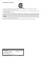
1
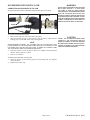
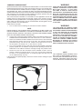
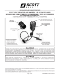
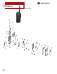
INSTALLATION AND USE INSTRUCTIONS
SCOTT EPIC 3 lapel Speaker mic (LSM)
with Accessories
FOR USE WITH SCOTT RESPIRATORS
RED EMERGENCY BUTTON
(ONLY ON CERTAIN MODELS)
EPIC 3 Lapel
Speaker Mic
ASSEMBLY (LSM)
RADIO SPECIFIC
CONNECTOR
Optional Accessories:
• Push-to-talk Paddle
TYPICAL PORTABLE RADIO
TRANSCEIVER
(NOT INCLUDED)
• Push-to-Talk Ring
• Command Throat Mic Kit
• Command comms headset
WARNING
THESE EPIC 3 LAPEL SPEAKER MIC AND ACCESSORIES ARE INTENDED TO BE USED WITH SCOTT
RESPIRATORS WHICH MAY SUPPORT HUMAN LIFE IN HAZARDOUS ATMOSPHERES. FAILURE
TO CAREFULLY FOLLOW THESE INSTRUCTIONS AND WARNINGS AND THE INSTRUCTIONS
AND WARNINGS CONTAINED IN YOUR SCOTT RESPIRATOR OPERATING AND MAINTENANCE
INSTRUCTIONS MAY RESULT IN SERIOUS INJURY OR DEATH.
WARNING
This product is designed and intended to function properly in reasonable/ordinary
firefighting conditions. Like all equipment, the functionality of this product may be
compromised by extreme fire conditions
© 2015 Scott Safety. SCOTT, the SCOTT SAFETY Logo, Scott Health and Safety, EPIC 3 RI, AV-2000, and AV-3000 are registered and/or
unregistered marks of Scott Technologies, Inc. or its affiliates.
Page 1 of 12
P/N 595293-01 Rev C 06/15
Conditions of safe use
This equipment is listed as intrinsically safe by CSA Group to UL Std. UL-913 for use in the following hazardous locations:
• Class I/II, Division I Groups C, D, E, F and G T4
This equipment is listed as intrinsically safe by CSA Group to CSA C22.2 No. 60079-11 for use in the following hazardous locations:
• Ex ia IIB T4 (Canada)
• Class I Zone 0 AEx ia IIB T4 (USA)
To maintain the Intrinsic Safety Listing, inspect equipment regularly per the Regular Operational Inspection procedures in this instruction. Do not tamper with or substitute components in any manner. Use only batteries of the type indicated in the Battery Installation
section of these instructions. Do not mix old batteries with unused batteries, or from different manufacturers Open the battery compartments only in an area known to be free of flammable or explosive hazards. Due to the potential for electrostatic discharge, clean with
dampened cloth only. Do not use dry cloth to clean the surface. Do not clean and maintenance device in an explosive environment.
When connected to a portable Two-way radio, the use of the assembly/radio combination in flammable atmospheres is limited to
the most restrictive listing applicable to the two devices
This product is Intrinsically safe when used in accordance with control drawing 31003129.
Approved Batteries
Alkaline Batteries:
– Eveready Energizer1 Max E92
– Eveready Energizer Industrial EN92
– Duracell2 Copper Top MN2400
– Duracell Pro-Cell PC2400
– Rayovac3 824
Rechargeable Batteries:
– Duracell Rechargeable (NiMH) DC2400
P/N 595293-01 Rev C 06/15
Page 2 of 12
Contents
Conditions of safe use..........................................................................................................................2
GENERAL DESCRIPTION..............................................................................................................................4
QUESTIONS OR CONCERNS........................................................................................................................4
Connecting lsm to A PORTABLE TWO-WAY RADIO............................................................................5
RADIO CABLES AVAILABLE FOR THE lsm............................................................................................................5
USE OF THE lsm WITH A TWO-WAY PORTABLE RADIO..........................................................................6
ACCESSORIES FOR THE EPIC 3 lsm..........................................................................................................7
Connecting accessories to the LSM .........................................................................................................7
PUSH-TO-TALK Ring................................................................................................................................................8
PUSH-TO-TALK Paddle ..........................................................................................................................................8
Command comms Headset................................................................................................................................9
Command Throat mic Kit.................................................................................................................................10
CLEANING, INSPECTION, AND MAINTENANCE....................................................................................... 11
CLEANING............................................................................................................................................................... 11
INSPECTION............................................................................................................................................................ 11
MAINTENANCE........................................................................................................................................................ 11
WARRANTY...................................................................................................................................................12
Page 3 of 12
P/N 595293-01 Rev C 06/15
GENERAL DESCRIPTION
The SCOTT EPIC 3 Lapel Speaker Mic (LSM) is designed for use with a SCOTT
approved portable two-way radio (supplied by the user). Training is required before
use. These assemblies are not intended for use under water or for any purpose not
specifically authorized by the organized program that applies to the specific user.
The system consists of an lsm fitted with a cord/connector specific to a particular
brand and model of portable two-way radio, and these instructions.
When connected to a portable two-way portable radio, pressing the large push-to-talk
button on the LSM will activate the push-to-talk function of the two-way portable radio.
The user may then speak into the LSM to transmit over the portable two-way radio.
Certain lsm models are equipped with a RED Emergency Button operate the corresponding emergency alert feature on compatible portable radios. Refer to the user
manual for your portable two-way radio for details of use. If the RED Emergency Button
is not installed on your unit, that feature is not available.
When the lsm assembly is connected to a portable two-way radio, the use of the
assembly/radio combination in flammable atmospheres is limited to the most restrictive hazardous location listing applicable to the two devices. If the LSM assembly is
connected to a non-intrinsically safe radio, the combination may not be used in flammable or explosive atmospheres.
The lsm assembly is available in a variety of cord/connector configurations to fit
popular brands and models of portable two-way radios. Each configuration has a
unique part number representing the radio specific connector used to attach it to the
portable two-way radio for which it was designed. Do not attempt to attach an lsm
assembly to a portable two-way radio for which it was not designed.
Optional Push-To-Talk Paddle and Push-To-Talk Ring accessories can be actuated
when worn under an encapsulating protective garment. Also available are a command comms headset with microphone and a throat mic KIT that includes a
throat mic, ear buds and push-to-talk ring. If these accessories are being used with
a two-way portable radio in a fire fighting application, the two-way portable radio, all
cables, and the accessory must be contained within the fire fighter’s turnout gear for
protection from heat and flame.
EMERGENCY
BUTTON
MICROPHONE
WARNING
Training IS REQUIRED BEFORE USE,
ESPECIALLY IN AN EMERGENCY SITUATION.
USE OF THIS EQUIPMENT WITHOUT PROPER
TRAINING COULD LEAD TO SERIOUS INJURY
OR DEATH.
WARNING
THE USE OF AN INTRINSICALLY SAFE DEVICE
IN AN ATMOSPHERE FOR WHICH IT IS NOT
LISTED OR THE USE OF A NON-INTRINSICALLY
SAFE DEVICE IN A FLAMMABLE OR EXPLOSIVE
AT M O S P H E R E M AY L E A D TO F I R E O R
EXPLOSION RESULTING IN SERIOUS INJURY
OR DEATH.
WARNING
When the SCOTT EPIC 3 Lapel Speaker Mic
assembly is connected to a portable
two way radio, the use of the assembly/
radio combination in flammable OR
EXPLOSIVE atmospheres is limited to
the most restrictive INTRINSIC SAFETY
listing applicable to the two devices.
IF THE EPIC 3 Lapel Speaker Mic assembly
IS CONNECTED TO A NON-INTRINSICALLY
SAFE RADIO, THE COMBINATION MUST NOT
BE USED IN FLAMMABLE OR EXPLOSIVE
ATMOSPHERES.
THE USE OF A NON-INTRINSICALLY SAFE
DEVICE IN A FLAMMABLE OR EXPLOSIVE
AT M O S P H E R E M AY L E A D TO F I R E O R
EXPLOSION RESULTING IN SERIOUS INJURY
OR DEATH.
CAUTION
PUSH-TO
TALK BUTTON
SPEAKER
Accessory
CONNECTION
With cap
Each configuration of the EPIC 3 Lapel
Speaker Mic assembly is designed to fit
a specific brand and model portable
two-way radio. Do not attempt to
connect the EPIC 3 Lapel Speaker Mic
assembly to a different brand or model
portable two-way radio. Attempting to
connect the EPIC 3 Lapel Speaker Mic
to a different brand or model radio
may cause damage to the EPIC 3 Lapel
Speaker Mic assembly, the radio, or
both.
RADIO
CABLE
WARNING
EPIC 3 LAPEL SPEAKER MIC (LSM)
QUESTIONS OR CONCERNS
If you have any questions or concerns regarding use of this equipment, contact your
authorized SCOTT distributor, or contact SCOTT at 1-800-247-7257 (or 704-291-8300
outside the continental United States).
P/N 595293-01 Rev C 06/15
Page 4 of 12
DO NOT USE accessories IN APPLICATIONS
which MAY EXPOSE IT TO HIGH HEAT
OR FLAME. If used in a fire fighting
application, All accessories and cables
must be contained within the fire
fighter’s turnout gear for protection
from heat and flame. EXPOSURE TO HIGH
HEAT OR FLAME MAY CAUSE THE accessory
TO MELT OR BURN WHICH COULD RESULT IN
SERIOUS INJURY or DEATH TO THE USER.
Connecting lsm to A PORTABLE TWO-WAY RADIO
The following instructions apply to the use of a lsm with a portable two-way radio.
All cords must be positioned such that they do not interfere with the function of the
respirator or present a safety hazard to the user.
1. Attach the radio connector from the lsm to the portable two-way radio
according to the instructions provided with the two-way portable radio.
2. The user must place the radio on his person so that the radio is protected
and securely attached. There must not be excessive slack in the cord
from the LSM to the radio which could present a hazard of snagging.
3. Position lsm where it will be readily accessible. Secure the cord to the
two-way portable radio.
4. If the lsm is being used with a two-way portable radio in a fire fighting
application, two-way portable radio and radio cable must be contained
within the fire fighter’s turnout gear for protection from heat and flame.
WARNING
DO NOT expose portable two-way radio
or cable to HIGH HEAT OR FLAME. If used
in a fire fighting application, radio and
cables must be contained within the fire
fighter’s turnout gear for protection
from heat and flame. EXPOSURE TO HIGH
HEAT OR FLAME MAY CAUSE THE radio or
cable TO MELT OR BURN WHICH COULD
RESULT IN SERIOUS INJURY or DEATH TO
THE USER.
WARNING
DO NOT POSITION THE PORTABLE TWO-WAY
RADIO CONNECTED TO THE EPIC 3 Lapel
Speaker Mic assembly SO THAT THE
CONNECTING CORD IS EITHER EXCESSIVELY
LOOSE OR EXCESSIVELY TIGHT. POSITION THE
CORD SO THAT IT WILL NOT POSE A SNAGGING
HAZARD WHICH MAY RESULT IN SERIOUS
INJURY OR DEATH.
FOR FIRE FIGHTING APPLICATIONS,
THE TWO-WAY PORTABLE RADIO AND
THE RADIO CABLE MUST BE PROTECTED
UP TO THE POINT SHOWN.
(CABLE ILLUSTRATED IS TYPICALRADIO APPEARANCE MAY VARY)
PROTECTION OF TWO-WAY PORTABLE RADIO AND RADIO CABLE
RADIO CABLES AVAILABLE FOR THE lsm
HARRIS models
P7300 SERIES / XG SERIES.............P/N 201244-22
KENWOOD Models TK 280/5220/5320, NX 210/410..........P/N 201244-07
MOTOROLA ModelsAPX 6000/7000 Series Radios......P/N 201244-06
MOTOROLA ModelsHT750, HT1250...................................P/N 201244-04
MOTOROLA Models XTS 1500, XTS 2500,
XTS 3000, XTS 3000R,
XTS 3500, XTS 5000 V3-10711..........P/N 201244-02
Page 5 of 12
P/N 595293-01 Rev C 06/15
USE OF THE lsm WITH A TWO-WAY PORTABLE RADIO
Before use, the user must understand the limitations of the portable two-way radio,
especially any limitations for use in an explosive or flammable atmosphere. The user
must also inspect and test the portable two-way radio in accordance with the radio
manufacturer’s operating manual for the radio being utilized.
To use the lsm attached to a portable two-way radio proceed as follows:
1. Verify that the LSM has been properly connected to the radio as instructed
in the Connecting lsm to A PORTABLE TWO-WAY RADIO section
of this instruction.
2. Turn ON the portable two-way radio according to the instructions provided with the two-way portable radio. The LSM will only operate when
the radio is ON.
3. Test the operation of the assembly pressing the Push-To-Talk button on
the lsm to activate the send function of the portable radio.
a. Talking into the LSM assembly should result in voice communications through
the portable radio.
b. The radio should indicate that it is transmitting (see radio manufacturer’s
operating manual).
If the unit does not operate properly, remove the unit from service and
tag for repair or replacement.
4. Adjust the speaker volume of the LSM using the volume control on the
portable two-way radio.
5. To transmit a message over the portable
two-way radio, press the Push-To-Talk button on the side of the lsm housing. When
connected to a portable radio, pressing this
button will activate the Push-To-Talk function of the radio.
6. The Belt Clip on the back of the lsm rotates for attachment. There are eight (8)
detents to hold the selected position.
7. Certain lsm models are equipped with a
RED Emergency Button operate the corresponding emergency alert feature on compatible portable radios. Refer to the user
manual for your portable two-way radio
for details of use. If the RED Emergency
Button is not installed on your unit, that
feature is not available.
P/N 595293-01 Rev C 06/15
Page 6 of 12
WARNING
U nderstand and follow the
instructions and limitations provided
by the manufacturer of the portable
two-way radio used with the EPIC 3
Lapel Speaker Mic assembly. Failure
to use the portable two-way radio in
accordance with the manufacturer’s
instructions may result in failure of
the radio AND LOSS OF COMMUNICATIONS
WHICH COULD RESULT IN serious injury
or death.
CAUTION
Attempting to connect an EPIC 3 Lapel
Speaker Mic assembly to a radio other
THAN the specific model the EPIC 3 Lapel
Speaker Mic assembly is designated
for use with may cause damage to the
assembly, the radio, or both.
CAUTION
THE TWO-WAY PORTABLE RADIO MUST BE
ON and properly connected to the EPIC
3 Lapel Speaker Mic assembly FOR THE
SYSTEM TO OPERATE.
ACCESSORIES FOR THE EPIC 3 lsm
WARNING
Connecting accessories to the LSM
All accessories attach to the LSM Cable using the same type of connector.
Locking groove
Locking post
Twist sleeve to lock
post in place
DO NOT USE accessories IN APPLICATIONS
which MAY EXPOSE IT TO HIGH HEAT
OR FLAME. If used in a fire fighting
application, All accessories and cables
must be contained within the fire
fighter’s turnout gear for protection
from heat and flame. EXPOSURE TO HIGH
HEAT OR FLAME MAY CAUSE THE accessory
TO MELT OR BURN WHICH COULD RESULT IN
SERIOUS INJURY or DEATH TO THE USER.
Sleeve
Cap
To connect accessories to the LSM:
1. Remove the cap from the end of the LSM cable.
CAUTION
2. Align the locking groove on the sleeve of the accessory cable with the
INSTALL THE ACCESSORY CONNECTIONS
locking post on the LSM cable and push together.
Note
When properly aligned, the locking post will slide easily into
locking groove. The accessory cable is keyed to connect to the
LSM cable only one way. DO NOT FORCE. If unable to connect turn
the accessory cable 180 degrees and retry.
CAREFULLY. The accessory cable is
keyed to connect to the lapel speaker
mic cable only one way. DO NOT FORCE. If
unable to connect turn the accessory
cable 180 degrees and retry.
3. Twist the sleeve to lock the post in place. An audible click will indicate
that the locking post is in place.
4. Test the connection.
To disconnect accessories from the LSM:
1. Twist the sleeve so the locking groove and locking post are aligned;
then pull apart.
2. Replace the cable cap.
Page 7 of 12
P/N 595293-01 Rev C 06/15
PUSH-TO-TALK Ring
Optional Push-To-Talk Ring and strap accessory SCOTT P/N 201226-01. This
Push-To-Talk Ring includes a hook and loop backing that can be attached to an accompanying hook and loop finger strap.
The Push-To-Talk Ring can be actuated when worn on finger under an encapsulating
protective glove. When installed, the Push-To-Talk Ring operates the same as the
Push-To-Talk Button on the side of the LSM assembly.
The Push-to-Talk Ring accessory is not intended for use in applications which may
cause exposure to high heat or flame. If the accessory is being used with a two-way
portable radio in a fire fighting application, the two-way portable radio, cables, and
the accessory must be contained within the fire fighter’s turnout gear for protection
from heat and flame.
Install and use as follows:
1. Connect the Push-To-Talk Ring cable to the LSM according to the CONNECTING ACCESSORIES TO THE LSM section of this instruction.
2. Turn on the portable two-way radio
and verify that the Push-To-Talk
Ring is operating properly. When
connected properly, pressing this
ring will activate the Push-To-Talk
function of the radio.
3. Position the Push-To-Talk Ring
where it can be easily actuated
with the other safety equipment
worn.
4. Secure Push-To-Talk Ring in place
using the Velcro straps
PUSH-TO-TALK RING
5. After donning, secure the cord
from the Push-To-Talk Ring so that it will not present a hazard of snagging while in use. The cord must be positioned so that it is not excessively
loose or excessively tight and does not pull on the LSM assembly any way.
If the unit does not operate properly, remove the unit from service and tag for repair
or replacement.
PUSH-TO-TALK Paddle
Optional Push-To-Talk Paddle accessory SCOTT P/N 201227-01. This Push-To-Talk
Paddle can be actuated when worn under an encapsulating protective garment. When
installed, the Push-To-Talk Paddle operates the same as the button on the side of
the LSM assembly.
The Push-to-Talk Paddle accessory is not intended for use in applications which may
cause exposure to high heat or flame. If the accessory is being used with a two-way
portable radio in a fire fighting application, the two-way portable radio, cables, and
the accessory must be contained within the fire fighter’s turnout gear for protection
from heat and flame.
Install and use as follows:
1. Connect the Push-To-Talk Paddle cable to the LSM according to the
CONNECTING ACCESSORIES TO THE LSM section of this instruction.
2. Turn on the portable two-way radio and verify that the Push-To-Talk Paddle
is operating properly. When connected
properly, pressing this button will activate the Push-To-Talk function of
the radio.
3. Position the Push-To-Talk Paddle
where it can be easily actuated with
the other safety equipment worn.
4. After donning, secure the cord from
the Push-To-Talk Paddle so that it will
not present a hazard of snagging while
in use. The cord must be positioned
PUSH-TO-TALK PADDLE
so that it is not excessively loose or
excessively tight and does not pull on the LSM.
If the unit does not operate properly, remove the unit from service and tag for repair
or replacement.
P/N 595293-01 Rev C 06/15
Page 8 of 12
WARNING
DO NOT USE THE OPTIONAL PUSH-TOTALK ring or Push-to-talk paddle IN
APPLICATIONS which MAY EXPOSE IT TO HIGH
HEAT OR FLAME. If used in a fire fighting
application, All accessories and cables
must be contained within the fire
fighter’s turnout gear for protection
from heat and flame. EXPOSURE TO HIGH
HEAT OR FLAME MAY CAUSE THE PUSH-TOTALK ring or Push-to-talk paddle TO
MELT OR BURN WHICH COULD RESULT IN
SERIOUS INJURY or DEATH TO THE USER.
WARNING
The cord from the PUSH-TO-TALK ring or
Push-to-talk paddle MUST BE SECURED
so that it will not present a hazard of
snagging while in use. The cord must be
positioned so that it is not excessively
loose or excessively tight and does
not pull on the EPIC 3 LAPEL SPEAKER MIC
ASSEMBLY. FAILURE TO PROPERLY MANAGE
THE CORD FROM THE PUSH-TO-TALK ring
or Push-to-talk paddle MAY RESULT IN
SNAGGING THE CORD IN AN EMERGENCY
SITUATION WHICH COULD RESULT IN SERIOUS
INJURY OR DEATH.
NOTE
The Push-To-Talk button on the
Lapel Speaker Mic housing will
continue to operate when other
push-to-talk accessories are
plugged into the Lapel Speaker Mic.
Command comms Headset
Optional Command Comms Headset SCOTT P/N 201229-01. The Command Comms
Headset is designed for two-way radio communication with a two-way portable radio.
This Command Comms Headset includes an earpiece speaker and a microphone
with adjustable arm. When connected to the radio, the headset will disable the radio
speaker and microphone and route all communication directly into the headset speaker
and microphone. The Command Comms Headset microphone operates using the
Push-To-Talk Button on the side of the LSM assembly.
The Command Comms Headset is not intended for use in applications such as fire
fighting which may cause exposure to high heat or flame. If the accessory is being
used with a two-way portable radio in a fire fighting application, the two-way portable
radio, cables, and the accessory must be contained within the fire fighter’s turnout
gear for protection from heat and flame.
Install and use as follows:
1. Turn off radio before installing the Command Comms Headset
NOTE
Installation of the headset while the radio is on may cause the
radio to transmit constantly, locking up your radio system. If this
should happen, turn off the radio. The radio can then be turned
back on, restoring normal operations.
2. Connect the Command Comms Headset cable to the LSM according to the
CONNECTING ACCESSORIES TO THE LSM section of this instruction.
3. Place the Command Comms Headset around the back of the head with
both earpieces resting over the top of the ears. The speaker should be
positioned directly over the left ear. Adjust the microphone arm so that
the microphone is situated 1/2” or less from the mouth.
4. Turn on the portable two-way radio and verify that the headset is operating
properly. Speak into the headset microphone while pressing the Push-ToTalk button on the LSM to transmit a message through the portable radio.
5. Secure the cord from the Command Comms Headset so that it will not
present a hazard of snagging while in use. The cord must be positioned
so that it is not excessively loose or excessively tight and does not pull
on the LSM assembly any way.
If the unit does not operate properly, remove the unit from service and tag for repair
or replacement.
WARNING
DO NOT USE THE OPTIONAL command comms
headset ACCESSORY IN APPLICATIONS
WHICH MAY EXPOSE IT TO HIGH HEAT
OR FLAME. If used in a fire fighting
application, All accessories and cables
must be contained within the fire
fighter’s turnout gear for protection
from heat and flame. EXPOSURE TO HIGH
HEAT OR FLAME MAY CAUSE THE command
comms headset TO MELT OR BURN WHICH
COULD RESULT IN SERIOUS INJURY or DEATH
TO THE USER.
WARNING
The cord from the command comms
headset MUST BE SECURED so that it will
not present a hazard of snagging while
in use. The cord must be positioned
so that it is not excessively loose or
excessively tight and does not pull
on the LAPEL SPEAKER MIC ASSEMBLY.
FAILURE TO PROPERLY MANAGE THE CORD
FROM THE command comms headset
MAY RESULT IN SNAGGING THE CORD IN
AN EMERGENCY SITUATION WHICH COULD
RESULT IN SERIOUS INJURY OR DEATH.
NOTE
The Command comms headset does
not have an independent push-totalk button. The microphone on the
headset operates using the pushto-talk button located on the LSM.
Earpiece
Speaker
Earpiece
Microphone
COMMAND COMMS HEADSET
Page 9 of 12
P/N 595293-01 Rev C 06/15
Command Throat mic Kit
Optional Command Throat Mic Kit SCOTT P/N 201228-01 is designed for two-way
radio communication with a two-way portable radio. This kit includes an adjustable
Command Throat Mic with magnetic fastener, an Ear Bud, and a Push-To-Talk Ring.
When worn around the neck the Command Throat Mic is designed to pick up and
transmit the vibration directly from your vocal cords. This assembly will disable the radio
speaker and microphone and route all outgoing communication directly from the Throat
Mic to the radio and all incoming communication back from the radio into the earbud.
The Command Throat Mic Kit accessory is not intended for use in applications which
may cause exposure to high heat or flame. If the accessory is being used with a twoway portable radio in a fire fighting application, the two-way portable radio, cables, and
the accessory must be contained within the fire fighter’s turnout gear for protection
from heat and flame.
Install as follows:
1. Turn off radio before installing the Command Throat Mic Kit.
2. Assemble the Command Throat Mic Kit.
a Plug the cable from the Connector to the LSM according to the CONNECTING THE ACCESSORIES TO THE EPIC 3 LSM section of this
instruction.
b Plug the cable from the Push-To-Talk Ring into the Connector.
c Plug the Lapel Clip into the Throat Mic.
d Plug the Earbud into the Lapel Clip and turn counterclockwise to lock.
WARNING
DO NOT USE THE OPTIONAL command throat
mic ACCESSORY IN APPLICATIONS WHICH
MAY EXPOSE IT TO HIGH HEAT OR FLAME.
If used in a fire fighting application,
All accessories and cables must be
contained within the fire fighter’s
turnout gear for protection from heat
and flame. EXPOSURE TO HIGH HEAT OR
FLAME MAY CAUSE THE command throat
mic TO MELT OR BURN WHICH COULD RESULT
IN SERIOUS INJURY or DEATH TO THE USER.
NOTE
I n sta l l ati o n o f t h e C o m m a n d
throat mic kit while the radio is on
may cause the radio to transmit
constantly, locking up your radio
system. If this should happen, turn
off the radio. The radio can then be
turned back on, restoring normal
operations.
WARNING
3. Place Throat Mic around neck with the microphone disc centered in
front. Adjust the straps to hold the Throat Mic securely in place without The cord from the command throat
mic MUST BE SECURED so that it will not
obstructing normal breathing. Secure with the magnetic fastener.
4. Place Earbud comfortably in ear and attach Lapel Clip to keep in place.
5. Turn on the portable two-way radio and verify that the Throat Mic is operating
properly. Speak in a normal voice while pressing the Push-To-Talk button on
the Push-To-Talk Ring to transmit a message through the portable radio.
6. Secure the cord from the Command Throat Mic so that it will not present
a hazard of snagging while in use. The cord must be positioned so that
it is not excessively loose or excessively tight and does not pull on the
LSM assembly any way.
If the unit does not operate properly, remove the unit from service and tag for repair
or replacement.
Lapel clip
d
Earbud
c
Throat mic
Connector
a
b
Push to
Talk Ring
To LSM
Command Throat Mic Kit
P/N 595293-01 Rev C 06/15
Page 10 of 12
present a hazard of snagging while
in use. The cord must be positioned
so that it is not excessively loose or
excessively tight and does not pull
on the LAPEL SPEAKER MIC ASSEMBLY.
FAILURE TO PROPERLY MANAGE THE CORD
FROM THE command comms headset
MAY RESULT IN SNAGGING THE CORD IN
AN EMERGENCY SITUATION WHICH COULD
RESULT IN SERIOUS INJURY OR DEATH.
CLEANING, INSPECTION, AND MAINTENANCE
CLEANING
1. After use, the LSM may be cleaned with a damp sponge. A solution of
water and mild dish detergent may be used if necessary.
2. Take care prevent excessive amounts of water from entering the holes
for the speaker or the microphone. DO NOT IMMERSE ASSEMBLY IN
LIQUID.
INSPECTION
After each use, inspect the LSM assembly for damage. If any damage is found, remove
the equipment from service and tag for repair by authorized personnel. No attempt to
disassemble or repair the LSM assembly shall be made.
1. Inspect the housing for cracks or other damage that could interfere with
the usability of the equipment.
2. Check for missing components.
3. Inspect the cables for cuts in the flexible wire, etc). If any damage to the
cable is found, remove the unit from service and tag for replacement. DO
NOT USE A UNIT WITH A DAMAGED CABLE.
4. Unused connectors must be capped when not in use.
WARNING
MAINTAIN THE EPIC 3 lapel Speaker mic
Assembly ONLY AS DIRECTED IN THIS
INSTRUCTION. DO NOT ATTEMPT DISASSEMBLY
OR REPAIR BEYOND THAT WHICH IS SPECIFIED
IN THIS INSTRUCTION OR IN THE INSTRUCTIONS
PROVIDED WITH SERVICE PARTS. IMPROPER
MAINTENANCE OR TAMPERING WITH THE
EPIC 3 Lapel Speaker Mic MAY RESULT IN
FAILURE OF THE COMMUNICATION SYSTEM
AND MAY LEAD TO SERIOUS INJURY OR DEATH.
MAINTENANCE
Except for cleaning and replacing the belt clip, no attempt shall be made to do maintenance or repairs beyond the scope of this instruction manual without proper training.
LSM BELT CLIP REPLACEMENT parts
Two Belt Clip styles are available for the LSM assembly. Replacement screws can
be ordered separately.
– Clothes Pin Belt Clip – P/N 31003083 (standard)
– Alligator Belt Clip - P/N 31003082
– Screw #4-40 X 3/16 - P/N 31002867
If the Belt Clip is damaged or missing, replace as follows:
1. Remove the four (4) screws holding the belt clip on battery door. Put aside
for installation of new belt clip.
2. If necessary, remove any dirt or debris from back of battery door.
3. Install new belt clip using the four (4) screws removed in Step 1. Tighten
until snug. DO NOT OVERTIGHTEN.
4. Verify that new belt clip rotates properly and clips into position.
5.Inspect the LSM assembly to verify that the battery door closes properly with the
belt clip installed. If any problems are observed, remove the unit from service
and tag for return to SCOTT or your SCOTT distributor.
Four (4)
belt clip
screws
Page 11 of 12
P/N 595293-01 Rev C 06/15
WARRANTY
Scott Safety
Limited Warranty on EPIC 3 Communication Products
and Accessories
SCOTT warrants all EPIC 3 communications devices, associated accessories,
unused consumable supplies, and carrying cases supplied with the products to be
free from defects in workmanship and materials under normal use and service for
one (1) year from the date of original manufacture by SCOTT. SCOTT’s obligation
under this warranty is limited to replacing or repairing (at scott’s option) the
products or components shown to be defective in either workmanship or materials.
Only personnel of SCOTT or, when directed by SCOTT, authorized SCOTT agents
are authorized to perform warranty obligations. This warranty does not apply to
defects or damage caused by any repairs of or alterations to the products made by
owner or any third party unless expressly permitted by SCOTT product manuals or
by written authorization from SCOTT. To obtain performance under this warranty,
and as a condition precedent to any duty of SCOTT, the purchaser must return such
products to SCOTT, a SCOTT authorized distributor or a SCOTT authorized service
center. Any product returned to SCOTT shall be sent to “SCOTT safety” (Attn:
Warranty Claim Dept.), P.O. Box 569, Monroe, NC 28111.
This warranty does not apply to any malfunction of or damage to the products
resulting from accident, alteration, misuse or abuse.
THIS WARRANTY IS MADE IN LIEU OF ALL OTHER WARRANTIES, EXPRESSED
OR IMPLIED INCLUDING, BUT NOT LIMITED TO, ANY IMPLIED WARRANTY OF
MERCHANTABILITY OR FITNESS FOR A PARTICULAR PURPOSE. IN ADDITION,
SCOTT EXPRESSLY DISCLAIMS ANY LIABILITY FOR SPECIAL, INCIDENTAL
OR CONSEQUENTIAL DAMAGES IN ANY WAY CONNECTED WITH THE SALE
OR USE OF SCOTT SAFETY PRODUCTS, AND NO OTHER FIRM OR PERSON
IS AUTHORIZED TO ASSUME ANY SUCH LIABILITY.
SCOTT SAFETY
Monroe Corporate Center
PO Box 569
Monroe, NC 28111
Telephone 1-800-247-7257
Fax (704) 291-8330
www.scottsafety.com
Printed in USA
P/N 595293-01 Rev C 06/15
Page 12 of 12