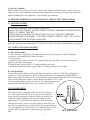
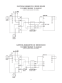
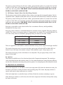
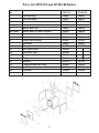
1
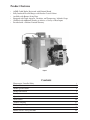
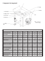
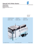
LV Series
Low Volume Boiler
LV Boiler
LVD, Direct Vent Boiler
Installation
Operation
Maintenance
Manual
COLUMBIA
COLUMBIA
®
COLUMBIA BOILER CO. OF POTTSTOWN
POTTSTOWN, PENNSYLVANIA 19464
Homeowner / Installer Policy
We at Columbia Boiler Company would like to “Thank You” for choosing our top of the line
LV Series Boiler. At Columbia Boiler we take pride in the serviceability and the quality
construction of our products. We have built trusting relationships that date back through our
company’s history to 1936. We believe that personal service is the best service and our
customers agree.
We would like to offer you a few helpful service points to insure your family years of trouble
free comfort. In order to maintain peak performance of your boiler, it is recommended that
your boiler be maintained annually. Servicing of your appliance must be performed by a
qualified oil heating technician. A properly trained oil technician will be prepared to set your
boiler/burner combination with the proper tools necessary to achieve your maximum comfort
and efficiency.
As a family owned business, we are happy to have you as one of our many satisfied
homeowners who have been choosing Columbia boilers for over 70 years. We look forward to
a long and continued relationship.
Rosemarie Bartchak
Sales and Marketing Manager
Columbia Boiler Residential Sales
i
Product Features
•
•
•
•
•
•
ASME Coded Boiler Registered with National Board
Fully Insulated Heat Exchanger with Powder-Coated Cabinet
Available with Burner Swing Door
Equipped with Triple Aquastat, Circulator, and Temperature / Altitude Gauge
Outfitted with Additional Nozzles to Achieve a Variety of Heat Inputs
Provided with a Lifetime Limited Warranty
Figure 1
Contents
Homeowner / Installer Policy
Product Features
Model Specifications
Model Dimensions
Installation
Operation
Maintenance
Trouble Shooting
Preliminary Settings
Parts List
Burner Service Set-Up Records
i
1
2
2
3
13
16
17
23
27
28
Component Arrangement
A*
SPECIFICATIONS
LV-75
LV-100
LV-110
LV-125
LV-135
LV-150
HEATING CAPACITY BTU/HR
89,355
118,300
128,600
150,000
160,000
174,000
IBR NET RATING BTU/HR
77,700
102,900
118,000
130,500
139,100
151,300
INPUT BTU/HR
105,000
140,000
154,000
175,000
189,000
210,000
0.75
1.00
1.10
1.25
1.35
1.50
8 X 8 X 15
8 X 8 X 15
8 X 8 X 15
8 X 8 X 15
8 X 8 X 15
8 X 8 X 15
+.05
+.08
+.10
0 - +.05
0 - +.065
0 - +.08
5.5 GAL.
5.5 GAL.
5.5 GAL.
8 GAL.
8 GAL.
8 GAL.
25"
25"
25"
25"
25”
25"
JACKET WIDTH
19-1/8"
19-1/8"
19-1/8”
19-1/8"
19-1/8"
19-1/8"
HYDRONIC SUPPLY HEIGHT
20-1/2"
20-1/2"
20-1/2"
20-1/2"
20-1/2"
20-1/2"
BURNER HEIGHT TO
9-3/8"
9-3/8"
9-3/8"
9-3/8"
9-3/8"
9-3/8"
HYDRONIC RETURN HEIGHT
5"
5"
5"
5"
5"
5"
FLUE OUTLET DIAMETER
5"
5"
5"
5"
5"
5"
25-1/2"
25-1/2"
25-1/2"
35"
35"
35"
5"
5"
5"
5"
5"
5"
HYDRONIC SUPPLY SIZE
1-1/4"
1-1/4"
1-1/4"
1-1/4"
1-1/4"
1-1/4"
HYDRONC RETURN SIZE
1-1/4"
1-1/4"
1-1/4"
1-1/4"
1-1/4"
1-1/4"
85.2
84.0
83.0
85.0
83.1
82.0
INPUT #2 OIL GPH
CHIMNEY SIZE
BOILER DRAFT LOSS INCHES
WATER CONTENT
BOILER HEIGHT w/AQUASTAT
*A = JACKET DEPTH
RETURN HEIGHT
DOE AFUE RATING
2
Installation
I GENERAL
This Series hot water steel boilers are high quality oil fired heating units. The installation of the unit
shall be in accordance with state and local regulations. Refer to local Installation Codes for Oil
Burning Equipment, for recommended installation practice.
II FREIGHT CLAIMS
All units should be inspected for damage upon arrival. Concealed damage claims should be filed
immediately against the carrier by the consignor. The carrier is responsible for taking prompt action on
all claims.
III SIZING
Replacement boilers should not be sized from the firing rate of the old boiler; a DOE sponsored study
indicated 65% of the heating units in U.S. homes are substantially oversized. A complete heat loss
calculation of the structure is necessary to choose the proper size unit to install. The boiler should be
sized to within 25% of the actual calculated heat loss of the structure. Over sizing will result in short
cycling and inefficient operation.
IV BOILER LOCATION
A) Boiler to be installed in a level position with clearances in accordance with NFPA 31 Table 10.6.1.
STANDARD CLEARANCES
Model
LV 75/100/110
LV125/135/150
Front
12"
24"
Sides
12"
6"
Rear
2"
6"
Chimney Connector
2"
18"
Floor
Approved for installation on
combustible flooring.
B) Reduced clearance installations shall comply with NFPA 31 Table 10.6.2.
C) To move the unit, push against the flue box or skids. Pushing or pulling the jacket or burner will
result in damage.
D) Be sure to level the unit by inserting shims under the elevated base.
E) TANK STAND ASSEMBLY. This series of boilers can be installed on the optional tank stand in
order to minimize floor space requirements when using the boiler in conjunction with an indirect
fired water heater.
The following procedure is required for the proper assembly of the tank stand:
a) Place the stand top upside down on a level floor.
b) Assemble the small cross braces by bolting them together through the center hole. Do not
at this time completely tighten the bolts.
3
c) Stand two of the legs up along the short side the top on the outside of the top. Fasten the
cross braces through the legs and tighten all bolts. Repeat for the other side.
d) Assemble the long side braces to the legs and themselves.
Place the tank stand on a level floor in its proper location before setting the boiler on top. If the
floor is not level be sure to level the stand by inserting metal shims under the tank stand legs.
Once the boiler is positioned on the stand do not attempt to move the stand.
F) Pipe and Flange Leg Mounting. The boiler base is suplied with two holes at each corner.
Circulator flanges may be installed at each corner under the base using the holes in the base and
the flange bolts. Use four sections of pipe of the same length, thread at each end and screwed into
the flanges at the four corners to create legs. Finish the stand by installing flanges at the ends of
the threaded pipes and securing the flanges to the floor usng fasteners appropriate for the floor.
The boiler may be leveled by screwing the pipes into or out of the flanges prior to securing the
flanges to the floor.
Item
Quantity
Description
1
1
Top
2
4
Legs
3
4
Large Cross Brace
4
4
Small Cross Brace
20
3/8-16 Bolts
20
3/8-16 Nuts
20
3/8-16 Washers
V. AIR FOR COMBUSTION AND VENTILATION - CHIMNEY VENT APPLICATIONS
The unit must be installed where provisions exist for combustion and ventilation air. Ordinarily,
provisions may be furnished by the following methods.
A) Utility Room or Closet
In buildings of tight construction, including most modern homes, you should provide an opening,
connecting to a well ventilated attic, crawl space or directly with the outdoors. The opening should
have a minimum free area of 1 square inch per 1,000 Btu per hour of total input for all appliances in
the enclosure and should terminate below the burner level. Boilers installed in confined areas or closets
must have two ventilation openings in the closet door. Each opening should have a free area of not less
than 1 square inch per 1000 Btu (140 square inch per US gph) of the total input for all appliances in
the enclosure. One opening located near the top of enclosure and one near the bottom.
B) Basement
1. When a boiler is installed in a full basement, infiltration is normally adequate to provide air for
combustion.
2. In buildings of tight construction when the basement windows are weather stripped, one opening to
a well ventilated attic or with the outdoors should be provided. (See part A for opening requirements)
4
C) Special Conditions
When a boiler is located in an area where exhaust fans, kitchen ventilation systems, clothes dryers, or
fireplaces may create conditions of unsatisfactory combustion or venting, special provisions should be
made for additional air for combustion, as specified by local authority.
VI. AIR FOR COMBUSTION AND VENTILATION - DIRECT VENT APPLICATIONS
A) VENTING SYSTEM
CAUTION: EXTERNAL VENT SURFACES ARE HOT.
NOTE: USE ONLY THE ETL LISTED VENTING SYSTEM COMPONENTS SUPPLIED WITH
THE TV-175 DIRECT VENT KIT.
SURFACE DISCOLORATION OF THE BUILDING MAY OCCUR DUE TO IMPROPER
BOILER/BURNER ADJUSTMENT. COLUMBIA BOILER COMPANY WILL NOT ACCEPT
ANY LIABILITY FOR SUCH DISCOLORATION.
Follow the instructions provided with the TV175 Direct Vent Kit for locating and installing the vent system.
VII JACKET AND TRIM ASSEMBLY
A) Knock Down Boiler
1. Jacket Assembly - Unpack the jacket parts being careful not to damage the finish. Piping and
accessories are installed after the jacket is in place.
2. Trim Assembly
a. Install the safety relief valve in the 3/4" tapping in the top of the boiler. The relief valve must be
piped to a safe place of discharge.
b. Install the limit control in the 3/4" fitting provided in the boiler.
c. Install the altitude/temperature gauge in the 1/4" fitting provided in the coil plate.
B) Packaged Boiler
Controls are installed and pre-wired at the factory. Burners on models 75, 100, 110 are shipped in a
separate box. To install the burner follow the burner manufacturer’s instructions included with the
burner, then connect the burner to the control using the quick connect fittings that are factory installed
on the control and burner harness sections. Burners on models 125, 135 and
150 are installed and pre-wired at the factory. See wiring diagram in this
manual for details. Install the relief valve as noted in Section 2a.
VIII BOILER PIPING
This style of boiler is equipped with a built in “Air Scoop system.” This feature allows quiet air free operation of your hot
water system by assuring the removal of noisy air pockets. The
supply line or Riser tapping in the top of the boiler extends
approximately 1" below the top or waterline of the boiler, thus
allowing only air free water to enter the supply to the heating system. The air trapped in the top of the boiler is then purged through a
3/4" vent tapping to be released with an (1) automatic float vent (2) a
manual vent or (3) piped into a conventional type expansion
tank.
5
BUILT IN AIR SCOOP
Relief valve discharges and drain valve piping must be piped to a safe place of discharge. All plugs and
water connections should be checked for leaks upon installation and annually.
This series of boilers virtually eliminates all standby losses with its low water content. Because this
boiler is also extremely efficient a bypass loop should be installed between the supply and return of the
boiler to maintain boiler water temperature during a call for heat. Consult the piping diagram in this
manual for typical bypass piping.
Regulation of the bypass is accomplished by use of a gate valve installed in the loop or a thermostatic
bypass valve. If a gate valve is used, it should be set to the full open position initially. Final adjustment of
the gate valve should be done as the system stabilizes. The valves should only be closed down enough to
ensure adequate heat to all system loops. If a thermostatic bypass is used, follow the manufacturers recommendations for installation.
Failure to install a bypass loop may cause excessive condensation causing premature failure of the boiler due to corrosion.
IX. STORAGE TANK PIPING
The recommended locations of circulators, expansion tanks, etc. are illustrated in the piping diagrams
included in this manual.
It is recommended that the indirect fired water heater be wired to give preference to the domestic water so
that when the tank thermostat calls for heat the flow of heat to the rest of the house is turned off.
Always consult the tank water heaters installation and operation manual for proper supply piping sizes,
location of T & P relief valve and any other information relating to the proper installation of the tank.
A thermal expansion tank may be required on those tanks which are equipped with check valves or
back flow preventers on the cold water supply.
X BURNER AND CONTROLS
A) Burner Installations
1. Remove the burner parts and instructions from the carton.
2. Referring to specifications at the back of the manual, check to see that the burner model and size
match the boiler model.
3. Make sure the correct nozzle is in place and is tightly sealed.
4. Check the electrode position and set the air intake as indicated in the burner manual.
5. The burner is installed with a mounting flange. The end of the burner air tube should be 1/4" from
the inside surface of the front wall of the combustion chamber.
6. Make the electrical connections as illustrated in the wiring schematics (provided by the burner and
controls manufacturer). All wiring must be done in accordance with the local electrical code.
7. For units installed in Maine, New Jersey and New York, a low-water cutoff is required on all hot
water boilers. Make the electrical connections as illustrated in the wiring schematics provided by the
low water cutoff manufacturer.
B) Oil Primary Control - Chimney Vent (Non Post Purge Control)
The oil primary control with the solid state flame sensing circuit provides automatic, non-recycling
control of oil burners. When used with the cadmium sulfide flame detector, the control will
automatically control the oil heating system.
6
FIGURE 2 - PIPING LAYOUT PREFERRED AND ALTERNATE METHODS
CIRCULATOR
AIR VENT OR
EXPANSION TANK
SUPPLYl
m
FLOW CONTROL
VALVE
AQUASTAT
SUPPLYl
FLOW CONTROL
VALVE
k
n
RELIEF
VALVE
n
AIR VENT OR
EXPANSION TANK
T & A GAUGE
n
k
THERMOSTATIC OR
MANUAL BYPASS
m
AQUASTAT
k
RETURN
n
n
ALTERNATE 1
STOP
VALVE
CIRCULATOR
n
n
n
n
DRAIN
VALVE
FILL
VALVE
BURNER
DOOR
n
THERMOSTATIC OR
MANUAL BYPASS
RELIEF
VALVE
n
n
T & A GAUGE
n
k
RETURN
STOP
VALVE
CIRCULATOR
ALTERNATE 2
AIR VENT OR
EXPANSION TANK
RETURN
n
l
AQUASTAT
k
n
k
T & A GAUGE
RELIEF
VALVE
m
n
SUPPLY
n
FILL
VALVE
DRAIN
VALVE
n
n
FILL
VALVE
STOP
VALVE
n
FLOW CONTROL
VALVE
THERMOSTATIC OR
MANUAL BYPASS
DRAIN
VALVE
BURNER
DOOR
PREFERRED
NOTES:
1. RELIEF VALVE MUST BE PIPED TO A SAFE PLACE OF DISCHARGE.
2. AIR VENT MAY BE PIPED TO NON BLADDER TYPE EXPANSION TANK.
3. A THERMOSTATIC BYPASS VALVE OR MANUAL VALVE MUST BE USED FOR A BALANCING VALVE.
4. THE FLOW CONTROL VALVE MAY BE REPLACED BY ZONE VALVES.
5. ALL PIPING MUST COMPLY WITH ALL STATE AND LOCAL CODES.
6. CONSULT HOT WATER TANK MANUFACTURERS LITERATURE FOR TANK PIPING.
7
BURNER
DOOR
ELECTRICAL DIAGRAM FOR LV SERIES BOILERS
TO CONNECT BURNER TO AQUASTAT
(APPLIES TO BECKETT CHIMNEY VENT BURNERS)
ELECTRICAL DIAGRAM FOR LV SERIES BOILERS
TO CONNECT BURNER TO AQUASTAT
(APPLIES TO RIELLO CHIMNEY VENT BURNERS)
8
ELECTRICAL DIAGRAM FOR LV SERIES BOILERS
TO CONNECT BURNER TO AQUASTAT
(APPLIES TO CARLIN CHIMNEY VENT BURNERS)
ELECTRICAL DIAGRAM FOR LVD SERIES BOILERS
TO CONNECT BURNER TO AQUASTAT
(APPLIES TO BECKETT DIRECT VENT BURNERS)
9
ELECTRICAL DIAGRAM FOR LVD SERIES BOILERS
TO CONNECT BURNER TO AQUASTAT
(APPLIES TO RIELLO DIRECT VENT BURNERS)
ELECTRICAL DIAGRAM FOR LVD SERIES BOILERS
TO CONNECT BURNER TO AQUASTAT
(APPLIES TO CARLIN DIRECT VENT BURNERS)
10
The primary control will stop the oil burner within a predetermined number of seconds if the fuel fails
to ignite or if the flame goes out during operation. The oil burner will remain off until the reset button
on the relay has been pushed. THE RESET MUST NEVER BE PRESSED MORE THAN ONCE
DURING A SINGLE FLAME FAILURE.
C) Oil Primary Control - Direct Vent (Post Purge Control)
The oil primary control with the solid state flame sensing circuit provides interrupted ignition. Used in
conjunction with a cadmium sulfide flame detector, the control will automatically control the oil burner.
The primary control will stop the oil burner within a predetermined number of seconds if the fuel fails
to ignite or if the flame goes out during operation. The oil burner will remain off until the reset button
on the relay has been pushed. THE RESET MUST NEVER BE PRESSED MORE THAN ONCE
DURING A SINGLE FLAME FAILURE.
Post-purge is provided to ensure that the boiler fires at maximum efficiency and dependability
throughout the heating season.
Post-purge of the oil burner is controlled through the electronic circuitry supplied. Post-purge timing is
variable. The factory set post-purge timing is at approximately one minute. It is recommended that it be
left at this setting. In no case should the post purge timing be reduced to less than 1 minute.
Length of Vent Kit
0 - 10 Feet
10.1 - 15 Feet
15.1 - 20 Feet
Minimum Post Purge Time
1 Minute
1 Minute
2 Minutes
Times are approximate and should be considered minimum settings for the length of intake pipe installed.
The length of post-purge may be increased on those units using the Beckett AFII or Riello BF-5 oil
burners to any value up to its maximum setting if field conditions require a longer purge cycle.
The length of post-purge on the Carlin burner is not adjustable. The post purge timing on the Carlin
burner is 90 seconds.
D) Aquastat
This control is installed in one of two locations shown in the Component Arrangement. The control provides a high limit function and circulator control. See the control manufacturers wiring diagrams and literature for more information concerning wiring and use options. See wiring diagram in this manual for details.
XI. SEQUENCE OF OPERATION
When room temperature or the indirect water heater temperature falls below the thermostat setting, the
thermostat calls for heat starting the burner and circulating pump. The burner and pump continue to
operate until room heating requirements are satisfied.
If the boiler high limit is reached the burner will shut off with the circulator continuing to operate.
If the thermostat continues to call for heat after the boiler temperature falls below the high limit setting
the burner will restart.
11
It is recommended that the indirect water heater be wired so that when its thermostat calls for heat the
flow of heat to the rest of the house is turned off. Consult the wiring diagrams from the indirect hot
water heater manufacturer for wiring details.
XII FUEL SYSTEM
A) Fuel Units
NOTE: Pump pressure 140 PSI for Beckett and Carlin, and 150 PSI for Riello.
1. Burners are commonly fitted with a single stage fuel unit. A single stage unit may be connected with
a supply line only, when the fuel supply is level with or above the burner. When the burner is above the
oil level, a return line should be provided between the fuel unit and the tank. A “by-pass” plug in the fuel
unit is then required. The return line automatically purges air from fuel units and returns it to the tank.
2. Two stage fuel unit. If the height difference between the burner and the fuel supply level exceeds
10 ft., a two stage unit should be used, and a return line should be installed.
B) Tubing
Use continuous heavy walled copper tubing with flare fittings only. Locate fittings in accessible
locations. If possible, tubing should be installed under the floor. Running tubing against boiler casings
or across ceiling or floor joints should be avoided.
C) In-Line Oil Filter
The oil filter should be of a generous capacity. It should be located inside the building between the
tank shut off valve and the burner. A shut off valve and the oil filter should be located as close to the
burner as possible for ease of servicing.
D) Oil Shut Off Valve
Install manual oil shut off valves at the burner and near the tank on the supply line. Both valves should
be easily accessible.
XIII FLUE SYSTEM - CHIMNEY VENT APPLICATIONS
A) General
AN OIL FIRED UNIT SHALL BE CONNECTED TO A FLUE HAVING SUFFICIENT DRAFT AT
ALL TIMES TO ASSURE PROPER OPERATION.
B) Draft
The draft regulator should be installed in accordance with the manufacturers instructions. Set the draft
to negative .02 to .04 inches W.C. in the stack.
C) Roof Clearances
The flue gas exit of the venting system should be at least 3 feet above the highest point where it passes
through the roof and at least 2 feet higher than any portion of a building with 10 feet of the venting system.
D) Chimney Connectors
The horizontal length of a chimney connector should not exceed 10 feet unless a draft booster is used.
The connector should be pitched upward at least 1/4 inch to the foot. Use only high quality lock seam
smoke pipe. Each joint should be securely fastened with sheet metal screws. Chimney connectors
should be positioned to the shortest possible run of smoke pipe to the chimney.
12
E) Vent Cap
Install a U.L. listed vent cap where the possibility of down drafts exist.
F) Boiler Venting
This boiler must be vented into a properly sized chimney, or into an Underwriters Laboratories Inc. listed venting device which is capable of maintaining the specified draft requirements.
As indicated in this manual, chimney sizes, draft requirements and other additional service and
installation requirements are essential for safe and proper operation of the boiler.
Only a trained experienced serviceman should attempt the installation or service of any boiler and or
venting device.
All venting installations must comply with the recommendations of the venting manufacturer and
with all state and local codes.
XIV WIRING
All external wiring must conform with the National Electric Code and local codes. Refer to burner and
controls manufacturer’s wiring diagrams for field wiring.
A) Field connections should be protected with a 15 amp fuse.
B) Install the room thermostat on an inside wall away from cold drafts, windows, or heat from
fireplaces, appliances, or sunlight. Connect the thermostat leads to the “TT” terminals on the circulator
control.
XV WARRANTY
The limited warranty is not applicable unless these installation instructions are followed.
Operation
I START UP
DO NOT START UNLESS CLEAN OUT DOORS ARE IN PLACE.
A. Make sure service switch to boiler is off.
B. Make sure boiler has been filled with enough water until the entire system has been purged and
desired pressure is obtained.
C. Check to make sure the oil storage tank is filled with No. 2 heating oil.
D. Make sure all manual shut off valves in the fuel system are open.
E. Set limit switch at 200°F.
F. Install a pressure gauge in the 1/8" gauge port, or bleed valve port of the fuel pump. The
pressure should be set per Installer/Serviceman Label.
G. Adjust the burner air band and air shutter in accordance with Installer/serviceman Label.
H. Push the safety reset button on the primary control and release. Adjust the thermostat to call for
heat. Turn the service switch to the on position. Bleed the fuel unit. If burner fails to start, refer to the
trouble shooting guide in this manual.
I. With the burner running, bleed the fuel unit again until all air is eliminated from lines. Close
and tighten the bleed port.
J. Check all lines and plugs for oil leaks and eliminate.
13
II START UP ADJUSTMENTS
A)
1.
2.
3.
4.
5.
Equipment Required
CO2 analyzer
Draft gauge.
Fuel pressure gauge.
Stack thermometer.
Smoke tester.
B) Burner Adjustments
Allow the burner to operate steadily for at least 15 minutes. Check the burner settings according to the
installer/serviceman label for your model, printed at the end of this manual, and make the following
adjustments:
1. Sampling Hole - punch 1/4" hole in the flue between the flue box and the draft regulator. All test
readings should be taken from this point.
2. In The Stack Draft - Take a draft reading from the flue pipe sampling hole. Adjust the barometric
draft regulator to -.02" in the stack. In tall chimneys a second draft regulator may be required in the
flue pipe to regulate draft under high draft conditions.
3. Overfire Draft - Take a draft reading from the draft port located to the left of the burner. Compare
the readings with those according to the installer/serviceman labels for Series I and II boilers starting
on page 30. Reinstall the draft port plug after all readings have been taken.
4. Pump Pressure - Adjust the pump discharge pressure per value on serviceman label.
5. Combustion Air - Reduce the air supply to allow just sufficient air for clean combustion. This is
accomplished by loosening the lock screws on the air shutter, and closing the air shutter until a trace of
smoke is recorded. Take a CO2 sample. Open the air shutter lowering CO2 about 1-1/2% to 2%. A zero
smoke reading should result. If this adjustment cannot be obtained, refer to the trouble shooting section
in this manual.
C) Instructing the Homeowner
The care and operation of the boiler should be explained to the homeowner, including care of the
burner, how to adjust the thermostat, necessity of air supply to the burner, and the simple checks to
make before calling the serviceman if the burner fails to operate automatically.
III BURNER SERVICING
A) Burner Components
If a replacement part is necessary, use only the part specified on the burner parts list in this manual.
Specify the part number and description when ordering. (See included burner literature).
B) Nozzles
Use only the correct nozzle specified on the “Installer/Serviceman” decal located on front boiler jacket.
Be extremely careful not to touch the nozzle orifice to avoid scratches or dirt which may cause leaks or
affect the oil spray pattern.
C) Electrode Settings
The electrode setting is critical for proper ignition of the fuel. Check to be sure electrode settings
comply with the specifications.
14
D) Fan and Blower Housing
The fan and blower housing should be kept clean from lint and dirt. If the boiler is located near an
unvented dryer, special care must be taken so that lint does not block air passages in the burner and
proper combustion air is provided.
IV HOMEOWNER INFORMATION
Your Serviceman/Service Company is:
Address:
Phone No.:
A) General
Never burn garbage or refuse in your heating unit. Never try to ignite oil by tossing burning papers or
other material into your boiler and never leave combustible material around it. Do not allow the fuel
tank to run out of oil. The fuel tank should be kept full during the summer or periods of non-use, to
prevent condensation of moisture on the inside of the tank.
B) Combustion Air Supply
Your burner requires an ample amount of clean combustion air in order to completely and efficiently
burn fuel. If an ample supply is not available erratic operation, noisy combustion, and fuel odors in the
air may result. Remember that venting fans or a vented dryer will greatly increase the need for outside
air.
C) Filter
Replace the cartridge filter in the line every year to avoid fuel unit and nozzle contamination.
D) Area Around Boiler
The area around the boiler should be kept clean and free of any combustible materials, particularly oily
rags or papers. The boiler should be accessible for ease of service. If the burner is shut down for an
extended period of time, shut off the manual fuel supply valve. Follow starting procedures to restart.
V SERVICE INFORMATION
To avoid unnecessary expense and inconvenience, the boiler and burner should be inspected at least
once a year by a qualified serviceman. If difficulty occurs, the following should be observed before
calling the serviceman.
A)
B)
C)
D)
Check to be sure there is fuel in the tank.
Check to see if the thermostat setting is above room temperature.
Check to see if the service switch is in the on position.
Do not tamper with the unit or its controls.
15
Maintenance
I VENT SYSTEM
ESCAPING GASES ARE DANGEROUS. THE ENTIRE FLUE AND VENTING SYSTEM SHOULD
BE INSPECTED AT LEAST ONCE A YEAR BY A QUALIFIED SERVICEMAN.
II OIL FILTER
The oil filter cartridge should be replaced annually.
III CLEANING
At the beginning of each heating season, boiler flue passages and the oil burner should be checked for
cleanliness and if necessary they should be cleaned. The boiler may be cleaned from either the front or
rear by removing the jacket panel and the front or rear door. The following procedure is required for
inspection and cleaning of the boiler flue passages.
A) Turn off all electrical power to the boiler before inspecting and cleaning.
B) Remove either the boiler front or rear jacket panel.
C) Remove the 8 brass nuts which hold on the door. The front door swings open for access. The rear
door must be completely removed.
D) Remove the fire tube baffles.
E) If required remove scale and any soot deposits with a flexible 2” flue brush. Be careful not to
damage the front or rear insulation.
F) Replace the fire tube baffles.
G) Reinstall the door and tighten with the 8 brass nuts.
H) Reinstall the jacket panel.
I) Turn on all electrical power to the boiler.
DO NOT REMOVE THE REAR COVER AND REAR REFRACTORY FOR NORMAL
MAINTENANCE. SOOT OR SCALE MUST BE REMOVED FROM THE FRONT BURNER
OPENING ONLY.
IV OIL BURNER
A) Thoroughly brush clean the burner fan blades. Only with clean fan blades is proper combustion air
delivery possible.
B) Clean nozzle assembly and all air handling parts.
C) Check spacing and condition of the ignition electrodes.
D) Nozzles should be inspected every year for plugged distributor slots or plugged orifices. If it is
necessary to replace the nozzle, use only the specified nozzle to be sure that the replacement meets the
spray pattern specifications of the burner.
V GASKETS
Tighten the nuts on the water coil annually to prevent any gasket leaks. Deterioration due to coil gasket
leaks shall void the warranty.
VI WIRING
Check the electrical wiring for damage or frayed insulation.
16
Troubleshooting Guide
TROUBLE: BURNER DOES NOT START
SOURCE
PROCEDURE
CAUSES
REMEDY
Thermostat
Check Thermostat
Thermostat set too low.
Turn thermostat up.
Thermostat on “off ”or “cool.”
Switch to heat.
Open thermostat wires.
Repair or replace wires.
Loose thermostat connectors.
Tighten connection.
Faulty thermostat.
Replace thermostat.
Thermostat not level.
Level thermostat.
Check burner motor overload
switch. (If equipped)
Burner motor tripped on
overload.
Push reset button.
Check primary control safety
switch.
Primary tripped on safety.
Reset safety switch.
Check boiler disconnect switch
and main disconnect switch.
Switch open.
Close switch.
Tripped breaker or blown fuse.
Reset breaker or replace fuse.
Jump the FF terminals on
primary control, if the burner
starts, fault is in detector circuit.
Open cad cell wires.
Repair or replace wire.
Dirty cell face.
Clean or replace face.
Faulty cad cell.
Replace cad cell.
Check resistance across cad cell.
If 400-600 ohms cell is bad.
Replace cad cell.
Check for line voltage between
the black and white leads. No
voltage indicates no power to the
control.
Limit control switch open
Check limit setting.
Circuit
Overloads
Power
Cad Cell
Primary
Control
Burner
Jump terminals - if burner
starts replace control.
Open circuit between limit
control and disconnect switch.
Repair circuit.
Low line voltage or power
failure
Call utility company.
Check for line voltage between
orange and white leads. No
voltage indicates a faulty control.
Defective control.
Replace control.
Check for voltage at the black
and white leads to the burner
motor. Voltage indicates power
to motor and a fault in the
burner.
Pump seized.
Turn off power to burner.
Rotate blower by hand, check
for excessive drag. Replace
fuel unit or blower wheel.
Blower wheel binding.
Burner motor defective.
When checking burner adjustments always use instruments.
17
Replace burner motor.
TROUBLE: BURNER STARTS BUT DOES NOT ESTABLISH FLAME
SOURCE
PROCEDURE
CAUSES
REMEDY
Oil Supply
Check tank for oil.
Empty tank.
Fill tank.
Check for water in oil tank using
a dip stick coated with litmus
paste.
Water in oil tank.
Strip tank of water exceeding
2" in depth.
Listen for pump whine.
Fuel supply valve closed.
Open valve.
Open pump bleed port and start
burner. Milky oil or no oil
indicates loss of prime.
Air leak in fuel system.
Repair leak, using only flared
fittings. Do not use Teflon
tape on oil fittings.
Listen for pump whine.
Oil filter plugged.
Replace filter cartridge.
Plugged pump strainer.
Clean Strainer.
Restriction in oil line.
Repair oil line.
Pump worn - low pressure.
Motor overloads.
Replace pump.
Coupling worn or broken.
Replace coupling.
Pump discharge pressure set
too low.
Set pressure according to the
installer/serviceman labels for
Series I & II boilers located at the
end of this manual.
Oil Line
and Filter
Oil Pump
Install pressure gauge in port of
fuel pump. Pressure should be
according to the installer/
serviceman labels for Series I & II
boilers located at the end of this
manual.
No spark or weak spark.
Ignition
Transformer
Ignition
Electrodes
Nozzle
Connect transformer leads to line
voltage. Listen for spark. Check
that transformer terminals are not
arcing with buss bars. Check that
transformer is properly grounded.
Line voltage below 102V.
Remove and inspect drawer
assembly.
Carboned and shorted
electrodes.
Clean electrodes.
Eroded electrode tips.
Incorrect electrode settings.
Replace and reset
electrodes.
Cracked porcelain insulators.
Replace and reset electrodes.
Plugged orifice or distributor.
Replace nozzle with nozzle
according to the installer/
serviceman labels for Series I & II
boiler located at the end of this
manual.
Check for faulty nozzle.
Call utility company.
Plugged nozzle strainer.
Poor spray pattern.
Combustion
Air
Adjustments
Replace transformer.
Inspect nozzle for correct size
and specifications.
Incorrect nozzle installed.
Install correct nozzle.
See “Burner Adjustment
Instructions” in this manual.
Air shutter open too far.
Decrease air shutter setting.
Air band open too far.
Decrease air band opening.
When checking burner adjustments always use instruments.
18
TROUBLE: BURNER FIRES, BUT THEN FAILS ON SAFETY
SOURCE
PROCEDURE
CAUSES
REMEDY
Cad Cell
Check cad cell with ohmmeter. If
more than 2000 ohms, cad cell is
defective or dirty.
Faulty or dirty cad cell
Clean or replace cad cell.
Primary
Control
After burner fires, open cad cell
circuit if flame looks OK. If
burner continues to operate, fault
is in primary control.
Faulty primary control
Replace primary control.
Heat
Exchanger
Restriction
Inspect heat exchanger.
Plugged heat exchanger.
Clean out heat exchanger.
Burner
Motor
Burner motor trips on overload.
Turn off power and rotate blower
by hand to check for excessive
drag.
Line voltage below 102V
Call utility company.
Faulty motor.
Replace motor.
Pump or blower overloading
motor.
Replace blower or pump.
TROUBLE: TOO MUCH HEAT
SOURCE
PROCEDURE
CAUSES
REMEDY
Circulator
Check to see if operating control
is working properly.
Circulator does not stop
running.
Repair operating control.
Thermostat
Check thermostat settings and
calibration.
Thermostat set too high.
Reset thermostat.
Thermostat defective
Replace thermostat.
Thermostat out of calibration.
Recalibrate. Check level.
Flow valve dirty and stuck.
Clean flow valve.
Flow valve defective.
Replace flow valve.
Flow Valve
Check to see if flow valve is
operating properly.
When checking burner adjustments always use instruments.
TROUBLE: HIGH NET STACK TEMPERATURES
SOURCE
PROCEDURE
CAUSES
REMEDY
Nozzle
Check pump pressure with pump
gauge.
Nozzle overfiring due to high
pump pressure.
Reduce pump pressure according
to installer/serviceman labels for
Series I & II boilers located at the
end of this manual.
Heat
Exchanger
Check heat exchanger surfaces
for soot or scale fouling.
Heat exchanger fouled.
Clean heat exchanger.
Baffles
Check baffles installed.
Baffles not installed.
Install baffles.
19
TROUBLE: BURNER FIRES, BUT THEN LOSES FLAME
SOURCE
PROCEDURE
CAUSES
REMEDY
Poor Fire
Inspect flame for stability.
Unbalanced fire.
Replace nozzle with specified
nozzle.
Excessive draft.
Reduce draft setting.
Insufficient draft.
Increase draft.
Insufficient combustion air sources.
Increase combustion air sources.
Air leak in fuel system.
Repair leak - use only flare
fittings.
Water in oil tank.
Strip tank of water exceeding
2" in depth.
Fuel supply valve closed.
Open valve.
Restriction in oil line.
Clear oil line restriction.
Plugged fuel filter.
Replace filter cartridge.
Plugged pump strainer.
Clean Strainer.
Cold oil.
Use #1 heating oil.
Oil Supply
If burner loses flame prior to the
primary control locking out, fault
is in fuel system.
Combustion
Air
Reduce combustion air supply.
Too much combustion air.
Close air band and air to raise
CO2. Check with instruments.
Pump
Install pressure gauge in gauge
port of fuel pump. Pressure
should be according to installer/
serviceman labels for Series I & II
boilers located at the end of this
manual.
Pump discharge pressure
incorrectly set.
Set pressure according to
installer/serviceman labels for
Series I & II boilers located at
the end of this manual.
Coupling worn or broken.
Replace coupling.
Pump worn - low pressure
motor overloads.
Replace pump.
Excessive
Draft
Take a draft reading. Draft should
be according to installer/serviceman labels for Series I & II boilers
located at the end of this manual.
Incorrect draft setting.
Reduce setting. Install second
draft regulator if necessary.
Poor Flue
Gas Sample
Insert CO2 probe into heat
exchanger tube. If reading is
greater by 1/2% or more, sample
was being diluted near flue box.
Leak in flue system.
Sample CO2 in heat exchanger.
Testing
Method
Using a chemical absorption type
device, let instrument set after a
test before venting. If CO2
reading increases 1/2% fluid is
weak.
Weak fluid.
Replace fluid in testing device.
Nozzle
Check for faulty nozzle.
Plugged orifice or distributor.
Replace nozzle with specified
nozzle.
Seal flue system leak.
Plugged nozzle strainer.
Poor spray pattern.
When checking burner adjustments always use instruments.
20
TROUBLE: BURNER FIRES, BUT PULSATES
SOURCE
PROCEDURE
CAUSES
REMEDY
Draft
Take a draft reading. Draft should
be according to installer/
serviceman labels for Series I & II
boiler located at the end of this
manual, in the stack.
Down drafts.
Install vent cap.
Insufficient draft.
Increase draft setting.
Excessive draft.
Reduce draft settings, install
second draft regulator if
necessary.
Draft
Regulator
Inspect draft regulator for correct
location on flue system.
Improper installation.
Move draft regulator to
correct location.
Combustion
Air
See Table 1.
Inspect installation for
combustion air provisions.
Improper installation.
Provide sufficient sources of air
for combustion.
Open air band wide and take
CO2 reading.
Improper adjustment.
Adjust CO2 level - start with air
band wide open. Use instrument.
Bleed pump; inspect for air leaks
or water contamination.
Air leak in fuel system.
Compression fittings.
Repair leak - use only flare
joints.
Water in oil tank.
Strip tank of water exceed 2"
in depth.
Install pressure gauge in gauge
port of fuel pump. Pressure
should be according to installer/
serviceman labels for Series I & II
boiler located at the end of this
manual.
Pump discharge pressure
incorrectly set.
Set pressure according to
installer/serviceman labels for
Series I & II boiler located at the
end of this manual.
Coupling worn or broken.
Replace coupling.
Pump worn - low pressure
motor overloads.
Replace pump.
Check for faulty nozzle.
Plugged orifice or distributor.
Replace nozzle with nozzle
specified on burner housing.
Oil Supply
Pump
Pressure
Nozzle
Plugged nozzle strainer.
Poor spray pattern.
Heat
Exchanger
Restrictions
Inspect heat exchanger.
Plugged heat exchanger.
When checking burner adjustments always use instruments.
21
Clean out heat exchanger.
TROUBLE: INSUFFICIENT HEAT
SOURCE
PROCEDURE
CAUSES
REMEDY
Circulator
Check if circulator is operational.
Coupling worn or broken.
Replace coupling.
Pump binding.
Replace pump.
Circulator motor burned out.
Replace circulator motor.
Wiring from operating control
defective.
Repair wiring.
Operating control defective.
Repair or replace operating
control.
Check if circulator is correct
size.
Circulator too small.
Replace with proper circulator.
Check if circulator is up to
speed; check if voltage to
circulator is sufficient.
Circulator defective.
Repair circulator.
Insufficient voltage.
Call utility company.
Check thermostat settings.
Settings too low.
Increase setting.
Check thermostat location.
Bad location due to heat build
up.
Move thermostat to a better
location.
Check thermostat calibration.
Out of calibration.
Recalibrate. Level thermostat.
Flow Valve
Check flow valve for sticking in
partially closed position.
Flow valve not opening fully.
Clean or replace flow valve.
Radiation
Check for air in radiators.
Radiators airbound.
Bleed radiators.
Check to see if radiators are
sized properly.
Radiators inadequate.
Install adequate radiation.
Boiler
Determine structure heat load.
Boiler too small.
Additional heating capacity.
Piping
Check to see if piping is sized
properly.
Piping inadequate.
Install adequate piping.
Heat
Exchanger
Check heat exchanger for soot or
scale accumulation.
Insufficient heat transfer.
Clean heat exchanger.
Burner
Check pump pressure with
pressure gauge.
Insufficient pump pressure.
Increase pressure according to
installer/serviceman labels for
Series I & II boilers located at
the end of this manual.
Nozzle
Check nozzle for size and spray
angle.
Wrong nozzle installed.
Install specified nozzle.
Check for faulty nozzle.
Nozzle underfiring due to
defective nozzle.
Replace nozzle.
Thermostat
22
Preliminary Settings
INSTALLER/SERVICEMAN
INSTALLER/SERVICEMAN
Model Number
Burner Type
Model Number
LV-75
LV-100
LV-110
________________________
Riello
Riello
Burner Type
Riello
ZERO
Beckett
Beckett
AFII
AFII
AFII
________________________
Nozzle Type
.65 70B
.85 70B
.90 70B
________________________
Pump Pressure PSI ________________________
140
140
140
Head/Pin Position ________________________
0
0
3
Air Band
2.0
3.75
4.5
________________________
Air Shutter
N/A
N/A
N/A
________________________
Draft Over Fire
0 to +.1"
0 to +.1" 0 to +.1"
________________________
Draft In Stack
-0.02"
-0.02"
-0.02"
________________________
CO2 Reading
10-11.5% 10-11.5% 10-11.5%
________________________
F5
F5
F5
________________________
Nozzle Type
.65 60W
.85 60w
.90 60W
________________________
Pump Pressure PSI ________________________
150
150
150
Head/Pin Position ________________________
2.0
2.0
2.0
Air Band
N/A
N/A
N/A
________________________
Air Shutter
1.75
3.0
3.25
________________________
Draft Over Fire
+0.02"
+0.03"
+0.06"
________________________
Draft In Stack
-0.02"
-0.02"
-0.02"
________________________
CO2 Reading
10-11.5% 10-11.5% 10-11.5%
________________________
ZERO
Beckett
Burner Model
Burner Model
Smoke Reading
LV-75
LV-100
LV-110
________________________
Smoke Reading
ZERO
ZERO
ZERO
ZERO
NOTICE
Above settings are approximate. Final adjustments to be made
with proper test equipment. Be sure all oil lines are air free and
the use of flare fittings is recommended. See installation/service manual for detailed information.
NOTICE
Above settings are approximate. Final adjustments to be made
with proper test equipment. Be sure all oil lines are air free and
the use of flare fittings is recommended. See installation/service manual for detailed information.
INSTALLER/SERVICEMAN
INSTALLER/SERVICEMAN
Model Number
Burner Type
LV-75
LV-100
LV-110
________________________
Carlin
Carlin
Model Number
Carlin
Burner Type
Burner Model
EZ-1
EZ-1
EZ-1
________________________
Nozzle Type
.65 60°A
.85 60°A .90 60°A
________________________
Pump Pressure PSI ________________________
140
140
140
Head/Pin Position ________________________
0.75
0.85-1.00 1.10-1.25
Air Band
0.60
0.85
0.75
________________________
Air Shutter
N/A
N/A
N/A
________________________
Draft Over Fire
0 to +.1"
0 to +.1" 0 to +.1"
________________________
Draft In Stack
-0.02"
-0.02"
-0.02"
________________________
CO2 Reading
10-11.5% 10-11.5% 10-11.5%
________________________
Burner Model
Smoke Reading
Smoke Reading
ZERO
ZERO
LV-75
LV-100
LV-110
________________________
Beckett
Beckett
Beckett
AFG
AFG
AFG
________________________
Nozzle Type
.65 80A
.85 80A
.90 80A
________________________
Pump Pressure PSI ________________________
140
140
140
Head/Pin Position ________________________
F-3*
F-4
F-6
Air Band
1
1
1.5
________________________
Air Shutter
10 OPEN
10 OPEN 10 OPEN
________________________
Draft Over Fire
0 to +.1"
0 to +.1" 0 to +.1"
________________________
Draft In Stack
-0.02"
-0.02"
-0.02"
________________________
CO2 Reading
10-11.5% 10-11.5% 10-11.5%
________________________
ZERO
ZERO
ZERO
ZERO
*Equipped with low firing rate baffle.
AFG burners standard with delay oil valve.
NOTICE
Above settings are approximate. Final adjustments to be made
with proper test equipment. Be sure all oil lines are air free and
the use of flare fittings is recommended. See installation/service manual for detailed information.
NOTICE
Above settings are approximate. Final adjustments to be made
with proper test equipment. Be sure all oil lines are air free and
the use of flare fittings is recommended. See installation/service manual for detailed information.
23
INSTALLER/SERVICEMAN
Model Number
Burner Type
INSTALLER/SERVICEMAN
LV-75
LV-100
LV-110
________________________
Beckett
Beckett
Model Number
Beckett
Burner Type
Burner Model
Riello
NX
NX
NX
________________________
Nozzle Type
.60 60°B
.75 60°B .85 60°B
________________________
Pump Pressure PSI ________________________
175
175
175
Head/Pin Position ________________________
2.5
3.5
4.0
Air Band
N/A
N/A
N/A
________________________
Air Shutter
N/A
N/A
N/A
________________________
Draft Over Fire
+0.000"
+0.050"
+0.080"
________________________
Draft In Stack
-0.020"
-0.020"
-0.020"
________________________
CO2 Reading
10-11.5% 10-11.5% 10-11.5%
________________________
Burner Model
Smoke Reading
Smoke Reading
ZERO
ZERO
LVD-75
LVD-100
LVD-110
________________________
Riello
Riello
BF5
BF5
BF5
________________________
Nozzle Type
.65 60W
.85 60W
.90 60W
________________________
Pump Pressure PSI ________________________
150
150
150
Head/Pin Position ________________________
2.0
2.0
2.0
Air Band
N/A
N/A
N/A
________________________
Air Shutter
3.25
4.25
4.5
________________________
Draft Over Fire
0 to +.10" 0 to +.10" 0 to +.10"
________________________
Draft In Stack
-0.02"
-0.02"
-0.02"
________________________
CO2 Reading
10-11.5% 10-11.5% 10-11.5%
________________________
ZERO
ZERO
ZERO
ZERO
NOTICE
Above settings are approximate. Final adjustments to be made
with proper test equipment. Be sure all oil lines are air free and
the use of flare fittings is recommended. See installation/service manual for detailed information.
NOTICE
Above settings are approximate. Final adjustments to be made
with proper test equipment. Be sure all oil lines are air free and
the use of flare fittings is recommended. See installation/service manual for detailed information.
INSTALLER/SERVICEMAN
INSTALLER/SERVICEMAN
Model Number
Burner Type
LVD-75
LVD-100
LVD-110
________________________
Beckett
Beckett
Model Number
Beckett
Burner Type
Burner Model
Carlin*
AFII
AFII
AFII
________________________
Nozzle Type
.65 70B
.85 70B
.90 70B
________________________
Pump Pressure PSI ________________________
140
140
140
Head/Pin Position ________________________
0
0
3
Air Band
2.0
3.75
4.5
________________________
Air Shutter
N/A
N/A
N/A
________________________
Draft Over Fire
0 to +.1"
0 to +.1" 0 to +.1"
________________________
Draft In Stack
-0.02"
-0.02"
-0.02"
________________________
CO2 Reading
10-11.5% 10-11.5% 10-11.5%
________________________
Burner Model
Smoke Reading
Smoke Reading
ZERO
ZERO
LVD-75
LVD-100
LVD-110
________________________
Carlin*
Carlin*
EZ-1
EZ-1
EZ-1
________________________
Nozzle Type
.65 60°A
.85 60°A .90 60°A
________________________
Pump Pressure PSI ________________________
140
140
140
Head/Pin Position ________________________
0.75
0.85-1.00 1.10-1.25
Air Band
0.50
0.85
0.75
________________________
Air Shutter
N/A
N/A
N/A
________________________
Draft Over Fire
0 to +.1"
0 to +.1" 0 to +.1"
________________________
Draft In Stack
-0.02"
-0.02"
-0.02"
________________________
CO2 Reading
10-11.5% 10-11.5% 10-11.5%
________________________
ZERO
ZERO
ZERO
ZERO
*Requires Carlin Air Intake Adapter
NOTICE
Above settings are approximate. Final adjustments to be made
with proper test equipment. Be sure all oil lines are air free and
the use of flare fittings is recommended. See installation/service manual for detailed information.
NOTICE
Above settings are approximate. Final adjustments to be made
with proper test equipment. Be sure all oil lines are air free and
the use of flare fittings is recommended. See installation/service manual for detailed information.
24
INSTALLER/SERVICEMAN
INSTALLER/SERVICEMAN
Model Number
Burner Type
Model Number
LVD-75
LVD-100
LVD-110
________________________
Beckett
Beckett
Burner Type
Beckett
ZERO
Riello
Riello
F5
F5
F5
________________________
Nozzle Type
1.00 60A 1.10 60A 1.25 60A
________________________
Pump Pressure PSI ________________________
150
150
150
Head/Pin Position ________________________
2.0
3.0
4.0
Air Band
N/A
N/A
N/A
________________________
Air Shutter
3.5
3.75
6.25
________________________
Draft Over Fire
+0.05"
+0.07"
+0.09"
________________________
Draft In Stack
-0.02"
-0.02"
-0.02"
________________________
CO2 Reading
10-11.5% 10-11.5% 10-11.5%
_______________________
NX
NX
NX
________________________
Nozzle Type
.60 60°B
.75 60°B .85 60°B
________________________
Pump Pressure PSI ________________________
175
175
175
Head/Pin Position ________________________
2.0
3.5
4.0
Air Band
N/A
N/A
N/A
________________________
Air Shutter
N/A
N/A
N/A
________________________
Draft Over Fire
+0.045"
+0.100"
+0.125"
________________________
Draft In Stack
-0.025"
-0.030"
-0.075"
________________________
CO2 Reading
10-11.5% 10-11.5% 10-11.5%
________________________
ZERO
Riello
Burner Model
Burner Model
Smoke Reading
LV-125
LV-135
LV-150
________________________
Smoke Reading
ZERO
ZERO
ZERO
ZERO
NOTICE
Above settings are approximate. Final adjustments to be made
with proper test equipment. Be sure all oil lines are air free and
the use of flare fittings is recommended. See installation/service manual for detailed information.
NOTICE
Above settings are approximate. Final adjustments to be made
with proper test equipment. Be sure all oil lines are air free and
the use of flare fittings is recommended. See installation/service manual for detailed information.
INSTALLER/SERVICEMAN
INSTALLER/SERVICEMAN
Model Number
Burner Type
LV-125
LV-135
LV-150
________________________
Carlin
Carlin
Model Number
Carlin
Burner Type
Burner Model
EZ-1
EZ-1
EZ-1
________________________
Nozzle Type
1.00 60B 1.10 60B 1.25 60B
________________________
Pump Pressure PSI ________________________
140
140
140
Head/Pin Position ________________________
1.1/1.25
1.35/1.5
1.35/1.5
Air Band
1.25
1.35
1.50
________________________
Air Shutter
N/A
N/A
N/A
________________________
Draft Over Fire
0 to +.1"
0 to +.1" 0 to +.1"
________________________
Draft In Stack
-0.02"
-0.02"
-0.02"
________________________
CO2 Reading
10-11.5% 10-11.5% 10-11.5%
________________________
Burner Model
Smoke Reading
Smoke Reading
ZERO
ZERO
LV-125
LV-135
LV-150
________________________
Beckett
Beckett
Beckett
AFG
AFG
AFG
________________________
Nozzle Type
1.00 45B 1.10 45B 1.25 45B
________________________
Pump Pressure PSI ________________________
140
140
140
Head/Pin Position ________________________
V-1
V-1
V-1
Air Band
CLOSED
1.5
2
________________________
Air Shutter
10 OPEN
10 OPEN 10 OPEN
________________________
Draft Over Fire
0 to +.1"
0 to +.1" 0 to +.1"
________________________
Draft In Stack
-0.02"
-0.02"
-0.02"
________________________
CO2 Reading
10-11.5% 10-11.5% 10-11.5%
________________________
ZERO
NOTICE
Above settings are approximate. Final adjustments to be made
with proper test equipment. Be sure all oil lines are air free and
the use of flare fittings is recommended. See installation/service manual for detailed information.
ZERO
ZERO
ZERO
NOTICE
Above settings are approximate. Final adjustments to be made
with proper test equipment. Be sure all oil lines are air free and
the use of flare fittings is recommended. See installation/service manual for detailed information.
25
INSTALLER/SERVICEMAN
INSTALLER/SERVICEMAN
Model Number
Burner Type
Model Number
LV-125
LV-135
LV-150
________________________
Beckett
Beckett
Burner Type
Beckett
ZERO
Smoke Reading
ZERO
INSTALLER/SERVICEMAN
Burner Type
LVD-125
________________________
Beckett
Burner Model
NX
________________________
Nozzle Type
0.90 45°B
________________________
Pump Pressure PSI ________________________
175
Head/Pin Position ________________________
20.
Air Band
N/A
________________________
Air Shutter
N/A
________________________
Draft Over Fire
+0.170"
________________________
Draft In Stack
+0.000"
________________________
CO2 Reading
10-11.5%
________________________
Smoke Reading
Riello
ZERO
ZERO
ZERO
*Requires Carlin Air Intake Adapter
NOTICE
Above settings are approximate. Final adjustments to be made
with proper test equipment. Be sure all oil lines are air free and
the use of flare fittings is recommended. See installation/service manual for detailed information.
NOTICE
Above settings are approximate. Final adjustments to be made
with proper test equipment. Be sure all oil lines are air free and
the use of flare fittings is recommended. See installation/service manual for detailed information.
Model Number
Carlin*
AFII
EZ-1
BF5
________________________
Nozzle Type
1.00 60°B 1.00 60°B 1.00 60°B
________________________
Pump Pressure PSI ________________________
140
140
150
Head/Pin Position ________________________
8
110-125
1.0
Air Band
N/A
N/A
N/A
________________________
Air Shutter
5.0
1.25
6.00
________________________
Draft Over Fire
0 to +0.2" 0 to +0.2" 0 to +0.2"
________________________
Draft In Stack
0 to +0.1" 0 to +0.1" 0 to +0.1"
________________________
CO2 Reading
10-11.5% 10-11.5% 10-11.5%
_______________________
NX
NX
NX
________________________
Nozzle Type
0.90 45°B 1.00 45°B 1.10 45°B
________________________
Pump Pressure PSI ________________________
175
175
175
Head/Pin Position ________________________
2.0
2.5
3.0
Air Band
N/A
N/A
N/A
________________________
Air Shutter
N/A
N/A
N/A
________________________
Draft Over Fire
+0.070"
+0.120"
+0.200"
________________________
Draft In Stack
-0.020"
-0.020"
-0.020"
________________________
CO2 Reading
10-11.5% 10-11.5% 10-11.5%
________________________
ZERO
Beckett
Burner Model
Burner Model
Smoke Reading
LVD-125
LVD-125
LVD-125
________________________
ZERO
NOTICE
Above settings are approximate. Final adjustments to be made
with proper test equipment. Be sure all oil lines are air free and
the use of flare fittings is recommended. See installation/service manual for detailed information.
26
Parts List LV75/110 and LV125/150 Boilers
Item
No.
1
2
3
4
5
Not Shown
Not Shown
Not Shown
6
7
Description
Heat Exchanger
Fire Tuber Baffle
Combustion Liner
Insulation for Steel Burner Door
Burner Door Steel
Burner Door, Cast Door Complete
Insulation for Cast Burner Door
Cast Frame Gasket
Target Wall Insulation
Rear Door
Part Number
LV75/110
280000
280275
337804
337803
280264
280260
337810
337811
337816
280269
Part Number
LV125/150
280002
280274
337804
337803
280264
280260
337810
337811
337816
280269
8
9
10
11
12
13
14
15
22
Front Jacket Panel
Rear Jacket Panel
Left Jacket Panel
Right Jacket Panel
Top Jacket Panel
Aquastat
Temperature/Altitude Gauge
Relief Valve
Circulator
501070
501080
501100
501090
501065
552110
559560
570180
535030
Kit 502280
27
552110
559560
570180
535030
BURNER SERVICE SET-UP RECORDS
Initial Set Up
1
2
3
4
5
1. Date
2. Model Number
3. Firing Rate
4. Pump Pressure*
5. CO2
6. “0” Smoke
7. Gross Stack°F
8. Draft Over Fire
9. Replaced Filter Yes/No
10. Replaced Nozzle Yes/No
11. Clean Pump Filter Yes/No
12. Inspect Coil Gasket
13. Check for Leaks @ plugs/fittings
14. Brush Clean Flue Tube Passages
15. Vacuum Chamber/Flue Tubes
16. Clean Blower Wheel
17. Check/Set Electrodes
*See pump pressure according to the installer/serviceman labels for Series I and II boilers located at the end of
this manual
28
BURNER SERVICE SET-UP RECORDS
6
7
8
9
10
1. Date
2. Model Number
3. Firing Rate
4. Pump Pressure*
5. CO2
6. “0” Smoke
7. Gross Stack°F
8. Draft Over Fire
9. Replaced Filter Yes/No
10. Replaced Nozzle Yes/No
11. Clean Pump Filter Yes/No
12. Inspect Coil Gasket
13. Check for Leaks @ plugs/fittings
14. Brush Clean Flue Tube Passages
15. Vacuum Chamber/Flue Tubes
16. Clean Blower Wheel
17. Check/Set Electrodes
*See pump pressure according to the installer/serviceman labels for Series I and II boilers located at the end of
this manual
29
BURNER SERVICE SET-UP RECORDS
11
12
13
14
15
1. Date
2. Model Number
3. Firing Rate
4. Pump Pressure*
5. CO2
6. “0” Smoke
7. Gross Stack°F
8. Draft Over Fire
9. Replaced Filter Yes/No
10. Replaced Nozzle Yes/No
11. Clean Pump Filter Yes/No
12. Inspect Coil Gasket
13. Check for Leaks @ plugs/fittings
14. Brush Clean Flue Tube Passages
15. Vacuum Chamber/Flue Tubes
16. Clean Blower Wheel
17. Check/Set Electrodes
*See pump pressure according to the installer/serviceman labels for Series I and II boilers located at the end of
this manual
CC-5106
01/08 - 250