1
SEAR8
OWNERS
MANUAL
MODEL NOS.
30 GALLON
449.310310
449.310311
449.320310
449.320311
40GALLON
449.310410
449.310411
449.320410
449.320411
449.314410 SHORT
52 GALLON
449.310510
449.310530
449.310531
449.320510
449.320511
CAUTION
Read All Safety Guides
Before You Start to
Install Your Water Heater
KENMORE
SURVIVOR
ELECTRIC
WATER HEATER
SAFETY INSTRUCTIONS m
... See Page 2
INSTALLATION
AVOID UNNEEDED
SERVICE CALLS ...
Read the HELPFUL HINTS
CHECKLIST
on Page 13.
OPERATION
CARE AND MAINTENANCE
TROUBLESHOOTING
-- PARTS LIST w
SAVE THIS MANUAL
PRINTED IN U,S.A.
WARRANTY m
TM
INTRODUCTION
Thank you for buying your Kenmore Survivor electric water heater from Sears. The water heater is made of the lat'est in
non-metallic materials that will not rust or corrode. It will give you many years of hot water service when installed, operated-and
maintained following the guides in this manual.
Your water heater is completely assembled and ready to install. When installing,you must use a new temperature and pressure
relief valve (included with the water heater*). Please read Pages 4, 6 and 9 prior to installing a temperature and pressure relief
valve. Other tools and supplies you will need to install the water heater are listed on Page 3.
If you want your water heater professionally installed, talk to your Sears salesperson who will arrange a prompt, quality, warranted
installation by authorized installers. Please read your warranty on Page 16.
Almost all new products (automobiles, boats, clothing, plastic and wood items, etc.) have an odor or smell to them for a time. Your
Survivor water heater may also have a "new" smell or odor to it, due to the non-metallic materials used in the manufacturing
process. This "new" smell is not harmful to you and will disappear in a short time.
* NOTE: All Model Numbers listed in this Manual are sold and shipped with a factory instalted Temperature and Pressure Relief
Valve. This valve will open at 150 psi and/or 210°F (see Pages 4, 6 and 9).
TABLE OF CONTENTS
Page No.
Tools and Materials Needed ................................................. 3
Page No.
Where to Locate the Heater ......................................................3
Controls and Temperature Settings .....................................8-10
Care of Your Water Heater .................................................10-12
Removing the Old Water Heater ....................................... 3-4
Helpful Hints Checklist ............................................................13
Steps to Install ..................................................................... 4-10
Repair Parts........................................................................14-15
Temperature & Pressure Relief Valve.....................4, 6 & 9
Warranty ...................................................................................16
Electrical Wiring ............................................................7-8
GUIDES TO SAFELY INSTALL AND USE YOUR WATER HEATER
READ THIS BOOK CAREFULLY FOR ALL STEPS, GUIDES
AND RULES TO SAFELY INSTALL AND USE YOUR
WATER HEATER CORRECTLY. FOLLOW ALL STEPS
EXACTLY OR BODILY INJURY, PROPERTY DAMAGE, OR
DAMAGE TO THE WATER HEATERCOULD RESULT.
IF WATER SYSTEM PRESSURE IS OVER 80 PSI, BUY
AND INSTALL A PRESSURE REDUCING VALVE (WATER
PRESSURE REGULATOR) ON THE INLET PIPE TO THE
WATER HEATER. HIGH INLET PRESSURE SHORTENS
THE LIFE OF THE WATER HEATER AND OTHER WATER
USING APPLIANCES.
CHECKWITH YOUR LOCAL PUBLIC WORKS DEPARTMENT
FOR PLUMBING, ELECTRIC AND SANITATION CODES.
BE SURE TO FOLLOW THEIR CODES AS YOU INSTALL
THE WATER HEATER. IF YOU DO NOT KNOW HOW TO
MAKE SAFE ELECTRICAL WIRING AND PLUMBING
CONNECTIONS,
GET HELP FROM A LICENSED
ELECTRICIAN OR PLUMBER.
NOTE: To protect other equipment in the water system,
install the pressure reducing valve on the main water pipe
where water enters the house.
I
THIS WATER HEATERWORKS ON 240 VOLTS. SEE THE
SPECIFICATIONS ON PAGE 3, AND WIRING GUIDES ON
PAGE 7.
THE KENMORE SURVIVOR WATER HEATER HAS A
FACTORY INSTALLED TEMPERATURE AND PRESSURE
RELIEF VALVE (SEE PAGE 4). DO NOT REMOVE THIS
VALVE UNLESS THERE IS APPARENT DAMAGE TO IT.
SEARS AND THE MANUFACTURER ARE NOT LIABLE
FOR ANY DAMAGE THAT MAY OCCUR FROM TOO HIGH
OF A TEMPERATURE OR PRESSURE IN THE WATER
HEATERIF THIS RELIEFVALVE IS REMOVED. (SEE NOTE
ON TOP OF PAGE).
THE WATER HEATER TANK IS INSULATED WITH 2
INCHES OF FOAM TO HELP STOP HEAT LOSS. MORE
INSULATION IS NOT NEEDED. DO NOT INSTALL AN
INSULATING JACKET.
I
BE SURE YOU HAVE ALL THE TOOLS AND MATERIALS
YOU WILL NEED BEFORE STARTINGTHE INSTALLATION,
PAGE 3.
AFTERINSTALLJNG,DO NOT TURN ON AND OPERATETHE
WATER HEATER UNLESS... THE TEMPERATURE AND
PRESSURE RELIEF VALVE IS IN PLACE AND OPERATING
PROPERLY, YOU HAVE PROPERLY INSTALLED THE
DRAIN PiPE ON THE TEMPERATURE AND PRESSURE
RELIEF VALVE (SEE STEP 5 ON PAGE 6), THE VACUUM
RELIEFVALVE HAS BEEN INSTALLED (SEE PAGE 4), AND
YOU HAVE COMPLETELY FILLED THE WATER HEATER
WITH WATER(SEE STEP 7 ON PAGE6).
SPECIFICATIONS TABLE
MODEL
NUMBER
449.310310
449.310311
449.320310
449.320311
449,310410
449.310411
449.320410
449.320411
449.314410
449.310510
449.310530
449.310531
449.320510
449.320511
NOMINAL
TANK
CAPACITY
(Gallons)
ELEMENTS
(@240Volt_
Qt_
Waffage
30
3O
30
3O
40
40
4O
4O
40 Short
52
52
52
2
2
2
2
2
2
2
2
1
2
2
2
3800
3800
5500
5500
3800
3800
5500
5500
3800
3800
3800
3800
52
52
2
2
5500
5500
RECOVERY
RATE(_
(Gallons
Per Hour)
MAX FUSE OR
CIRCUIT
BREAKER SIZE
(Arnps)
2O
20
3O
3O
2O
2O
3O
3O
2O
20
2O
20
3O
3O
17.3
17.3
25,0
25.0
17.3
17.3
25.0
25.0
17.3
17.3
17.3
17.3
25.0
25.0
MINIMUM
WIRE SIZE
®
(Gauge No.)
12
12
10
10
12
12
10
10
12
12
12
12
10
10
DIMENSIONS
(Inches)
®
®
Diam.
Height
211/4
211/4
211/4
211/4
533/8
533/8
533/8
533/8
211/4
657/8
211/4
211/4
211/4
231/8
231/8
231/8
231/8
231/8
657/8
657/8
657/8
553/8
663/4
663/4
663/4
66,1/4
231/8
66_/4
- MAXIMUM
WORKING
PRESSURE
(PSI)
REC-OMMENDED
WORKING
PRESSURE
150
150
150
150
150
150
150
150
150
150
150
150
150
150
(PSi)
80
80
80
8o
80
80
80
80
80
80
80
80
80
80
(D At 90 ° F rise
@ Standard 60° C copper wire (local codes may specify other gauge if fuse or circuit breaker box is more than 90 ft. from water heater).
® Actual outside configuration is 16 equal sides. The front panel protrudes 1" to 11,_-beyond above nominal diameter.
® Includes factory installed temperature and pressure relief valve.
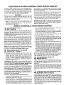
PLAN HOW YOU WILL INSTALL YOUR WATER HEATER
TOOLS AND MATERIALS
NEEDED
• Copper or galvanized pipe and fittings (3/4" minimum size)
as needed to make the plumbing connections (see FIG. 1,
Page 5 and FIG. 2, Page 6). GPVC plastic pipe and fittings
are permitted in some areas.
• You can buy water heater installation kits
from Sears. The kits include flexible connectors with 3/4" fittings to help make
installing the water heater easier.
I I
m
• Pipe thread seal compound.
• Electrical wiring materials as needed
(see Step 8 and Page 7).
t=!
ki
I
• Pipe wrenches (2), hacksaw or pipe cutter, wire stripper or
knife, a wire cutter, and a Phillips screwdriver. If installing
copper pipe and solder fittings, you will need a propane
torch, lead free solidcore solder (see following Note (_),
paste flux, emery cloth, sand paper or steel wool. If
installing CPVC plastic, solvent cement is needed.
O NOTE; For copper pipe installations, to help guard
against the adding of lead to water supplies, Federal law
prohibits the use of solder containing more than 0.2
percent of lead.
WHERE
TO LOCATE
THE WATER
HEATER
If you are replacingan old water heater, you willprobably want
to use the same location. If you want to change the location,
or if this is a new installation,considerthe following:
• Locate closeto where you will use the most hot water. Less
heat islost when the hot water has a shortdistanceto flow.
• Locate close to a floor drain, laundrytub or sink. A proper
(check local codes) drain is needed for the temperature
and pressurerelief drain pipe (see Page 6), and for monthly
drainingof the water heater (see Page 10).
• Do not install where water could freeze in the water heater.
Freezedamage voids your warranty from Seats (seePage 12).
• Do not install next to a wood-burning stove or other
appliance where high temperature could warp or otherwise
damage the water heater outer jacket.
~ .
• Put the water heater in a place water damage is least likely
if it should start to leak. If needed (see following note ® ),
make or buy a suitable drain pan and place it under the
water heater. The drain pan must have a free flowing drain
line to carry away water that may leak into it.
@ NOTE" Recommended by American National Standards
Institute (ANSI) Z21-10.1- (latest issue) under instruction
section, if water heater is located in or above an area that
could be damaged by water leaks.
• For ease of service, be sure you are able to get to the drain
valve, temperature and pressure relief valve, and access
panels to the controls.
• Be sure the floor is level so the water heater will stand
straight.
REMOVE THE OLD WATER HEATER
(if it applies)
1. TURN OFF ELECTRIC POWER TO THE WATER HEATERat
the fuse or circuit breaker panel.
If removing a gas water heater,TURN OFF THE GAS SUPPLY
TO THE HOUSE, disconnect and cap, or remove,the gas line
to the water heater (check local codes) and the vent pipe.
WARNING
I
I
FLAME DURING CAPPING OR REMOVING GAS LINE AS
I DO
NOT SMOKE,
CREATE
SPARKS OR USE OPEN I
AN EXPLOSION
MIGHT
RESULT.
2. Turnoff the water supply to the water heater.
PLAN HOW YOU WILL INSTALL YOUR WATER HEATER
4. DO STEP 1, if not already done. Then remove the water
heater junction box access cover. Disconnect electrical supply
wires to the water heater.
3. Fasten a length of garden hose to the water heater drain
valve. Place the other end of the hose at a suitable drain
point, lower than the drain valve (nearby floor drain, sink, tub,
or outside), open ,the drain valve and let all water drain from
the water heater. READ THE FOLLOWING WARNING.
WARNING
I
I
SURE NO ONE IS NEAR THE DRAIN HOSE OR THEY
J WATER
THE DRAIN
HOSE MAY BE VERY HOT. BE J
COULD FROM
GET BURNED
SEVERELY.
NOTE: For faster draining, open a hot water faucet, or the
temperature and pressure relief valve, so air can enter the
water heater plumbing system.
5. When all water has drained from the water heater, remove
the garden hose from the drain valve and close the valve.
6. Disconnect (or cut) the inlet and outlet water supply pipes
close to the water heater. Be careful not to damage the pipes
if you want to reuse them for installing your new water heater.
7. Remove and properly dispose of the old water heater.
CAUTION: Mineral buildup or sediment may have accumulated in your old water heater. This causes the water heater to be
much heavier than normal. The remaining water and residue, if
spilled out, could cause staining.
STEPS TO INSTALL YOUR WATER HEATER
union will be done later, this is to help aid in measuring the
amount of pipe or tube that may need to be cut.
RELIEF
• VACUUM
(FIG. 1, PAGE
5). VALVE
Your new water heater is designed to give you many years of trouble
free service. To help safeguard your water heater investment, a
VACUUM RELIEF VALVE has been included with the parts kit. It must
be installed according to the note below and the instructions on Page
5 to assure warranty coverage.
Certain conditions such as breakage in the main supply line, pump
failure on a well system or other plumbing system malfunctions may
cause a temporary pressure loss. The installation of the vacuum relief
valve on the cold water supply line to the water heater will allow air to
enter the tank and prevent damage in the event such conditions occur.
NOTE: The vacuum relief valve MUST be installed vertically at or
above the highest point of the tank. Do not install the shut-off valve
between the vacuum relief valve and the tank (see FIG. 1, Page 5).
NOTE: If your water pressure is over 80 PSI, be sure to install a pressure
reducing
valve (water pressure
regulator)
in the inlet
supply pipe to the water heater (seethe Safety Guides on Page 2).
WATER
SUPPLY
TO WATER
• COLD
HEATER
(FIG. 1,
PAGE 5).
•
Heat traps have been installed on your water heater to help
achieve the best operating
efficiency.
Heat traps help
prevent heat from flowing
from the inlet and out[et
plumbing connections during periods when the heater is not heating water. To replace a plugged or damaged heat trap due to
scale build-up, be sure to follow the "CAUTIONS" on Page 4 and
illustrations on Pages 5 and 13.
CAUTIONS: BE SURE TO INSTALL HEAT TRAPS AT THE CORRECT
WATER HEATER CONNECTION. OBSERVE FLOW ARROWS ON
THE HEAT TRAPS. IF INSTALLED WRONG, WATER FLOW
THROUGH THE WATER HEATER IS GREATLY REDUCED.
Use pipe joint compound or Teflon tape on the heat trap threads. The
last connection to the water heater must use the factory supplied
seal ring washers only. DO NOT use sealants with seal ring washers.
DO NOTREMOVECOLOREDPLASTICiNSERTSFROMTHE HEATTRAPS.
DO NOT SWEAT SOLDER DIRECTLY TO THE HEAT TRAPS. DO
ALL SOLDERING FIRST. THEN CONNECT HEAT TRAPS TO THE
PIPES AND TO THE WATER HEATER.
FOLLOWALL INSTALLATIONINSTRUCTIONSINTHIS MANUAL.
•
Thread the cold side heat trap into the 1" x 3/4" reducer bushing
using pipe joint compound or teflon tape.
•
Loosely assemble the 1" x 3/4" reducer bushing with the cold
side heat trap attached to the INLET (COLD) hex union. Be sure
the seal dng is in place in the hex union. (Use factory supplied seal
ring washers only. DO NOT use sealants with seal ring washer.)
DO NOT TIGHTEN THE HEX UNION. Tightening of the hex
•
Run a cold water supply line to the cold side heat trap using Sears
water heater installation kit (Page 3), threaded galvanized,
soldered copper or CPVC plastic pipe and fittings.
•
Be sure to include a shut-off valve and fittings
vacuum relief valve as shown in FiG. 1, Page 5.
•
Use pipe thread seal compound
or teflon tape on all
outside threads. The last connection to the water heater
must use the factory supplied seal ring washers only, DO
NOT use sealants with seal ring washers,
•
Read the following caution notes before tightening fittings,
soldering or cementing.
CAUTION: TO PREVENTHEATTRANSFER AND DAMAGE TO THE
iNLET FITTING AND HEATTRAR, DISCONNECT THE HEX UNION
NUT FROM THE REDUCERBUSHING AND THE HEATTRAP FROM '
THE SWEATTO FEMALE PIPE ADAPTOR BEFORE SOLDERING.
ALWAYSTIGHTEN THE HEX UNION LAST, AFTER PLUMBING IS
iN PLACE, ALIGNED, SOLDERED, ETC. DO NOT A'I7"EMPT TO
TURN PIPE OR FITTINGS AFTER HEX UNIONS ARE TIGHT OR
YOUWILL DAMAGETHE WATERHEATERBEYONDREPAIR.
for the
NOTE: If yourwater heater is installed using a check valve in the water
line or a water meter wwith a check valve, contact the Sears Service
Center or localwater authoriity on how to control-this situation.
= WATER
HOT WATER
PIPE FROM THE
HEATER.
Install the hot side heat trap to the outlet (HOT) hex union nut. Be
sure a seat ring is in the hex union (USE FACTORY SUPPUED SEAL
RING WASHERS ONLY.DO NOT USE SEALANTS WITH SEAL RING
WASHERS.)
Make all pipe to fitting connections the same way as you did in Step
2, observing the hex union and heat trap sweat to pipe adaptor fitting, caution and tightening procedures listed on Page 4. Refer to the
instructions on Page'4, Step 2, and FIG. A, Page 13 to replace a heat
trap.
• TEMPERATURE
VALVE (See * NoteAND
on PRESSURE
Page 2).
RELIEF
Your Survivor water heater was shipped with a temperature and
pressure relief valve factory installed. Do not operate the water heater
unless the temperature and pressure relief valve is in place and
working properly. A relief valve is essential for safety and to protect
the water heater. Too high of a temperature and/or pressure inside the
water heater could cause it to burst. The relief valve automatically
opens if temperature or pressure gets too high to relieve hot water
and/or pressure to the drain. READ AND COMPLY WITH THE
WARNING ON PAGE6.
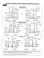
STEPS TO INSTALL YOUR WATER HEATER (Continued)
COLD WATER
WATER HEATER
INSTALLATION KIT
HOT WATER
Shut-off
Valve
Vacuum Relief
Valve (Included)
_-/
Flexible
3/4"
Installation
...m
Nipple
kd
Tube
3/4.
• Hot Side "---_!_
Heat Trap
I-1
L.J
tl
Female
Tee
_'
( "_
/_[ree_ _loow
I_Jl_
L_
HeatTrap
Cold Side
COLD
WATER
S_hut-off
Flexible
_j,.q
Installation-'---!
Tube
\
,
Hot Side
Heat Trap _
"_
_1
Seal Ring
(Included)
"_" Seal Ring
] (Included)
)_
[/
Inlet (COLD) Hex
Union Nut
.
Cold Side
Heat Trap
//
"_1
1" x 3/4" Reducer
xx
Relief
Valve
BushI,oduded)
og
"_
_r-_
WATER _
90° Elbow ,/_ I
OR
.
Seal Ring
(Included) /
/'-"
t / /
Outlet (HOT) Hex
Union Nut
_
r_,1_
jV_.L_.p
_=_
L2
_ 3/4" 90.,
3/4"
Female Tee
HOT
o
_1
Vacuum
Valve (Included)
LJ
"--.._ea
-'_--
_
_
_
{_p./"_._
--
--._,,'_(Inclu
Outlet (HOT) Hex
Union Nut
l" x 3/4" Reducer
Bushing (included)
,_
_eal Hing
dad)
Inlet (COLD) Hex
Union Nat
Vacuum Relief
Valve (Included)
_[_
COLD
WATER
/
Shut-off
Valve
*Gold Side
Heat Trap
{_-,_"
I" x 3/4" (Included)
Reducer
Bushing
Seal Ring
(Inc]uded)
Outlet (HOT) Hex
Union Nut
Inlet (COLD) Hex
Union Nut
Outlet (HOT) Hex
Union Nut
COLD WATER
THREADED
PIPE
vacuum
Inlet (COLD) Hex
Union Nut
Relief
Valve (Included)
HOT WATER
_
1
/
-
/
Union (2) --t:-:_
3/4" Female
_"-'=
Coupling
_]
_
Fe3/L:le
Tee
.
*Hot Side
Heat Trap
HOT WATER
_,
_
'FI_'
r_
Vacuum
_',_
Seal Ring . _
_
is _
Relief
I_--"
Valve (Inc uded)
'_
o
_"_
_--_. 3/4[ "gO'
,ree, ,oow
_.,,._,
tl
t_ _
!_
(Includ_
_
/-
'"UP
_r_
\k,..J
*Cold
Side Heat Trap
_.&
Union
v[: '
(2) l''''''
"""
3/4" Female.
OR
Coupling
Outlet (HOT) Hex
Union Nut
_
COLD
F_rnale
_
Tee
U
Shut-off
_
/
_/"_
_
WATER
Valve
(2)"',r_
•
"_.
*Hot Side "_=_
.eat.rap
Seal Rin
_
1" x 3/4" Reducer
Bushing (Included)
^,,f
I_
90 ° Elbow
_
(3
"Cold
Side
Heat Trap
_
_
_"
.,.
N
1" x 3/4" Reducer
Bushing (Included)
Seal _;_
Seal Ring
(,ncluded)K_--
_/F
_
Shut-off
,_
v
_-_/_
(Included)
k_ (Included)
Inlet (COLD) Hex
Union Nut
Outlet (HOT) Hex
Union Nut
Inlet (COLD) Hex
Union Nut
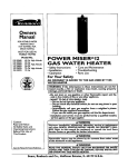
NOTE: The inlet fitting on electric water heaters is a 1-inch inside threaded hex union. Unions (dotted lines) are not needed if
the inlet and outlet pipes move enough to allow connection Dr if flexible supply lines are used:
* SEE PAGE 13 FOR HOTAND COLD HEAT TRAP INSTALLATION DETAILS.
5
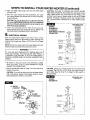
STEPS TO INSTALL YOUR WATER HEATER (Continued)
WARNING
I,i [__PJ
If the temperature and pressure relief valve ever needs replacing,
use onty a valve specified by local codes, but not less than a
combination temperature and pressure relief valve certified by a
nationally recognized testing laboratory that maintains periodic
inspection of production of listed equipment or materials meeting
the requirements for Relief Valves and Automatic Gas Shutoff
Devices for Hot Water Supply Systems, as specified in the latest
edition of ANSI Z21.22. This valve must be marked with a
maximum set pressure not to exceed the marked maximum
working pressure of the water heater. (The relief valve provided
with this heater meets these.requirements.)
Install the
replacement valve into the opening provided and marked for this
purpose on the water heater. Do not place any valve between the
temperature and pressure relief valve and the tank. Orient it or
provide tubing so that any discharge from the valve witll exit only
within 6 in. above (or any distance) below the structural floor and
cannot contact any live electrical part. The discharge opening
must not be blocked or reduced in size under any circumstances.
For maintenance and replacement of the temperature and
pressure relief valve see pages 10 and 11.
IMPORTANT; TO HELP PREVENT POSSIBLE DAMAGE TO
THE WATER HEATER, WE SUGGEST YOU READ STEP 5
CAREFULLY.
DRAIN PIPE RELIEF
FROM TEMPERATURE
• PRESSURE
VALVE.
AND
WARNING
The temperature and pressure relief valve is designed to
automatically open to vent dangerously high temperature or
pressure from the water heater. To vent the temperature or
pressure,the drain pipe must allow a free flow of water to a floor drain
or other suitable drain point (CHECK LOCAL CODES). If it cannot
vent properly, and fast enough, the heater could burst and damage
property, or cause severe personal injury. BE SURETO FOLLOW ALL
GUIDES BELOW WHEN INSTALLINGTHIS DRAIN PIPE. (Also read
the safety guides on page 2, and "WARNING" above.)
DO NOToperate the water heater unless the temperature and pressure relief valve is in place, correctly piped and working properly.
CAUTION: Do not apply heat to the fitting when making sweat
connections to the temperature and pressure relief valve. Sweat
an adaptor to the copper line before connecting to the valve. It is
imperative that no heat be applied to the water heater connections as they are joinedto the non-metalic structure of the heater.
• If the temperature
and pressure relief valve needs
repositioning, removing or replacing, two wrenches must
be used -- one to turn the valve and one to hold the union
hex nut. Never use only one wrench.
= Use 3/4" pipe and fittings the same size as the outlet of the
temperature and pressure relief valve. DO NOT USE A
SMALLER SIZE PIPE.
-e----.
_.
Temperature and
Pressure
Valve
Metal Strap or
Wire
Fastened
to
Overhead Point
•Seal Ring
_
for Support
I I\ The addition of
Hex Union _'
Nut
(Relief Valve
I I \a Union at this
II
point willhelp
[I
in the
II
replacement
of
[_
the
tri
Temperature
II
and Pressure
I]
Relief Valve
II
should the need
i;
Drain arise.
Pipe
I I
I I
IL_
I
....._--- ---- _
_--....L_-r-DqlIi_lt---T_
_
_-._
No Threads
./
Permitted
on End of Pipe
!_r
_-6"
Approximate
,_ _/_-"_"_DIs t an ce for
_
End of Drain
Pipe From Floor
Drain Valve
or Drain
__
• The end of the drain pipe must be no more than 6 in,
(maximum air gap) above the floor drain as FIG. 2 shows.
• The drain run must not have any dips, bends or low spots
that will trap water. ALL water must drain from the pipe and
relief valve.
• Be sure freezing temperatures will not affect the flow of '
water from the drain pipe.
• Support the drain pipe in some manner to prevent stress
on the water heater fitting. For example, use metal
strapping or wire to an overhead point as shown in FIG. 2.
Following ALL of the above RULES, install the drain pipe. Use
pipe thread seal compound on male pipe threads and tighten
all connections.
Solder all sweat connections.
(READ
CAUTION IN STEP 5,) REMEMBER DO NOT RESTRICT THE
DRAIN PIPE IN ANY WAY.
,, DRAIN VALVE (FIG. 2).
The drain valve is factory installed. To face the drain valve
outlet in the opposite direction, toward the drain point, FIRST
LOOSEN THE UNION HEX NUT. DO NOT ATTEMPT TO
TURN THE DRAIN VALVE WITHOUT LOOSENING THE HEX
NUT OR YOU WILL DAMAGE THE WATER HEATERBEYOND
REPAIR. POSITION DRAIN VALVE TO THE OPPOSITE
DIRECTION AND RETIGHTEN HEX NUT.
• Use material that will withstand hot water (210°F), and will
not distort, deform, melt, collapse, etc. Copper or CPVC
plastic pipe and fittings are best to use, to keep weight
stress on the center hex union at a minimum.
A. Be sure the water heater drain valve is closed by turning
the handle clockwise ( _
).
• DO NOT install valves or fittings in the drain pipe that will
restrict drain flow.
B. Open nearby HOT water faucets to allow air to vent from
the water heater and pipes.
• The end of the drain pipe must not have threads, so a
fitting or cap could be turned onto it by mistake.
C. Open the water heater cold water supply shut-off valve you
installed in Step 2.
WATER
WATER
• FILL
CHECK
FOR HEATER
PLUMBINGWITH
LEAKS.
AND
STEPS TO INSTALL YOUR WATER HEATER (Continued)
D. Open the MAIN water supply valve and the water heater
will begin to fill.
E. When the water heater has filled completely, and water
from nearby faucets runs smooth with no more air bubbles,
close the faucets.
CAUTION: Be sure to allow all air to vent from the tank.
The upper heatina element will burn out if air is trapped at
the top of the tank and the element is not covered with
water when power is turned on.
E Check your plumbing work for leaks. If any are found,
repair before doing the electrical wiring. READ THE
CAUTION NOTE FOLLOWING STEP 2 ON PAGE 4.
, ELECTRICAL
CAUTION: BE SURE TO GROUND THE WATER HEATER.
Rigid metal conduit (FIG. 3A), between the main pane( and the
water heater junction box, with approved end fittings, is the
preferred way to ground (check codes on the use of flexible
conduit). If making a separate ground wire connection (FIG.
3B), a ground screw is provided in the water heater junction
box.
WIRING
SCHEMATIC
STANDARD
NON-SIMULTANEOUS
OPERATION
From
240V Power
Source
WIRING.
t
Wire the water heater (240V) to the main fuse or circuit
breaker panel. Read all of the following notes, warnings and
cautions before beginning. Refer to FIG. 3A thru 3F on Pages
7 and 8.
i
Water
Heater
Junction
NOTE: Remove the water heater front panel (grasp with both
hands and pull outward) and the junction box cover.
Box
FOR MODEL NOS.
449.310310
449.310311
449.320310
449.320311
449.310410
449.310411
449.320410
449.320411
449.310510
449.310530
449.310531
449.320510
449.320511
Upper
Temperature
Control
Thermostat
(5PDT)
WARNING
IF YOU ARE NOT FAMILIAR WITH WIRING AND YOU
HAVE ANY DOUBTS, YOU SHOULD GET HELP FROM A
LICENSED ELECTRICIAN. IF YOU DO SOMETHING
WRONG, SEVERE BURN OR SHOCK HAZARDS CAN
RESULT.
Lower
Control
Thermostat
• BE SURE TO FOLLOW LOCAL AND NATIONAL CODES
AND ELECTRIC UTILITY REQUIREMENTS
WHEN
MAKING THE CONNECTIONS.
• See the specification table on Page 3 for wire and circuit
breaker or fuse size.
CAUTION: If you will use wiring from the old water heater,
and it is'aluminum, replace it with copper wiring or have a
licensed electrician make the connections.
Lower
I
CAUTION: Check your model number for the correct wiring
schematic. See FIG. 3C or FIG. 3D for the proper wiring of
each model. See FIG. 3E or 3F on Page 8 for time switch or
off-peak wiring.
FOR MODEL NOS.
449,314410
WIRING
SCHEMATIC
l.l[ .=:_]
A. METAL
CONDUIT
From
240V Power
Source
t
black
_red
Circuit Breaker
i
t
L
/Wi HGROUND
Junction
Limit
(l_ P
Box
Switch
_
-
1
Wa_er Heater
Junction
Box _H
w_re/H _/,_FI:_
red
co.t,oJ
Thermostat
black
_
green
Ground
Wire
(bare or
green)
r--_"_(
._"
!
'_
STEPS TO INSTALL YOUR WATER HEATER (Continued) _.
TIME SWITCH
OR OFF PEAK WIRING
I _ [_al_]_
• For TIME SWITCH or "OFF-PEAK" operation of the lower
element see either FIG.3E or 3F wiringschematic.
CAUTION: If you are going to wire the unit for either a
TIME SWITCH or "OFF-PEAK" operation, the black wire
from TerminalNo. 4 ofthe limit switch must be disconnected
and replaced totally or disconnected and joined with a new
section of wire using a proper connector. BE SURE TO
FOLLOW ALL LOCAL AND NATIONAL CODES AND
ELECTRIC UTILITY REQUIREMENTSWHEN MAKING THE
CONNECTIONS.
FOR MODEL
WIRING
SCHEMATIC
NON-SIMULTANEOUS
OPERATION
BOTTOM ELEMENT
ON SEPARATE
"OFF-PEAK"
METER
From
From
2,_v Power"Off-Peak'
Source
_
Meter
_=
€
Water Heater
Junction
Box
Dual element water heaters are designed to allow only one
element to heat at a time. This method is called
non-simultaneous operation and is necessary to avoid
overloading wiring in the house per the National Electric
Code. Off-Peak wiring methods must ensure proper use of
the high limit control in at least one line to each element
and use the non-simultaneous feature.
CAUTION:
Thermostat
(EPDT)
•
_
The
Upper Etemant
Lower
r
.j_._
_
FOR MODEL NOS.
449.310310
449.310311
449.320310
449.320311
449.310410
F,om
From
24OV Power
Time Clock
449.310411
Source
Switch
449.320410
_
,_
449.320411
_ = =
.=
449.310510
449.310530
tp,'
449.310531
449.320510
449.320511
NON-SIMULTANEOUS
OPERATION
BOTTOM ELEMENT
ON SEPARATE
SWITCH
Water
TIME
Healsr
Junction
kimil
Box
SWitCh
CAUTION:
_
Wpper
Element
t
_
_
_I
-
The black wire from
terminal No. 4 on the
Limit Switch must be
disconnected
and
reolaced totally or
disconnected and
joined with a new
section of wire. Be
sure
to follow
all
local and national
codes when maklnQ
this ccnnnecttan.
Lower
t_
disconnected
and
section
*'
.....
==
sure
of wire. Be
to follow
all local
and
national
realaced
totallycodes
or
_
_,
Eiemenl
and
ioined with a new
Thermostat
Lower
disconnected
when
makinc
this
"------J
- WATER HEATER START-UP.
To comply with safety regulations, the Kenmore Survivor
water heater is factory set to heat water to 120 degrees F. At
this •temperature, water is hot enough for most household : '
needs. A setting of 120° F, or lower if local codes require, is
recommended as a starting point.
Safety and energy conservation are factors to be considered
when selecting the water temperature setting of water heater's
thermostat. The lower the setting the greater the safety and
savings in energy and operating cost.
TIME/TEMPERATURE
Temperature
120° R
RELATIONSHIPSIN SCALDS
Time to Produce Serious Burn
More than 5 minutes
125 ° E
11/2to 2 minutes
130 ° F.
About 30 seconds
135 ° R
About 10 seconds
140 ° E
Less than 5 seconds
_
Temperalure"-'_-'_
Control
Thermostat
(SPOT)
Upper
wire from
',
Conlrol
IF YOU ARE NOT FAMILIAR WITH WIRING AND YOU
HAVE ANY DOUBTS, YOU SHOULD GET HELP FROM A
LICENSED ELECTRICIAN. IF YOU DO SOMETHING
WRONG, SEVERE BURN OR SHOCK HAZARDS CAN
RESULT.
WIRING
SCHEMATIC
I
Temperature
CAUTION: DO STEP 7, PAGE 6 BEFORE TURNING ON
ELECTRICAL POWER TO THE WATER HEATER.
black
terminal No. 4 on the
Limit Switch must be
WARNING
REPLACE THE JUNCTION BOX COVER after you have
made the wiring connections.
NOS.
449.310310
449.310311
449.320310
449.320311
449,310410
449.310411
449.320410
449.320411
449.310510
449.310530
449.310531
449.320510
449.320511
145 ° R
Less than 3 seconds
150 ° R
About 11/2seconds
155 ° R
About 1 second
Tat_ cour_sy of Sh_
Bum h_st#ute
STEPS TO INSTALL YOUR WATER HEATER (Continued)_
If the factory setting is satisfactory for your needs, replace the
front panel and turn on the electric supply to the water heater.
CAUTION: BE SURE THE WATER HEATER IS COMPLETELY
FULL OF WATER BEFORE TURNING ON THE ELECTRICITY
(SEE STEP 7 ON PAGE&) Be sure the cold water supply to
the water heater is fully on.
If you want to set the water heater to a higher temperature,
DO NOT TURN ON THE ELECTRIC POWER. FIRST READ
THE TEMPERATURE CONTROLS SECTION AND ALL
WARNINGS.
WARNING
WATER TEMPERATURE
OVER 125 DEGREES
FAHRENHEIT CAN CAUSE BURNS OR DEATH FROM
SCALDS. CHILDREN, DISABLED AND ELDERLY ARE
AT HIGHER RISK OF BEING SCALDED. ALWAYS FEEL
WATER BEFORE BATHING
OR SHOWERING.
TEMPERATURE LIMITING VALVESWITH INSTRUCTIONS
ARE AVAILABLE FROM PLUMBING SUPPLY AND
HARDWARE STORES.
THERMAL
EXPANSION
Water supply systems may, because of high line pressure,
frequent cut-offs, the effects of water hammer and others,
have installed devices such as pressure-reducing valves,
check valves, back flow preventors, etc.., to control these
types of problems. When these devices are not equipped with
an internal by-pass, and no other measures are taken, the
devices cause the water system to be closed. As water is
heated, it expands (thermal expansion) and closed systems
do not allow for the expansion of heated water.
The water within the water heater tank expands as it is heated
and increases the pressure of the water system. If the relieving
point of the water heater's temperature and pressure relief
valve is reached, the temperature and pressure relief valve will
relieve the excess pressure. The temperature and pressure
relief valve is not intended for the constant relief of thermal
expansion. This is an unacceptable condition and must be
corrected. Do not plug the temperature and pressure relief
valve.
If the system has any devices installed which could create a
closed system, install a by-pass and/or an expansion tank to
relieve the pressure built by thermal expansion in the water
system. Expansion tanks are available for ordering through
the Sears Service Center. Contact the local water supplier
and/or Sears Service Center for assistance in controlling these
situations.
TEMPERATURE
RELIEF VALVE
TEMPERATURE
CONTROLS
The upper, and lower heating elements have the same kind of
temperature
control thermostats.
MODEL NUMBER
449.314410 HAS ONLY A LOWER HEATING ELEMENT AND
CONTROL THERMOSTAT.The thermostat(s) are factory set to
keep the water at approximately 120 degrees Fahrenheit. At
120 degrees Fahrenheit, water is hot enough for most
household needs.
Safety and energy conservation are factors to be considered
when selecting the water temperature setting of water heater's
thermostat. Water temperatures above 120 ° E can cause
severe burns or death from scalding. Be sure to read and
follow the warnings outlined below.
Maximum water temperatures occur just after the elements
have shut off. To find hot water temperature being delivered,
turn on a hot water faucet and place a thermometer in the hot
water stream and read the thermometer.
The following chart may be used as a guide in determining the
proper water temperature for your home.
TIME/TEMPERATURE RELATIONSHIPSIN SCALDS
Temperature
120 ° E
Time to Produce Serious Burn
More than 5 minutes
125 ° F.
11/2to 2 minutes
130 ° E
About 30 seconds
135 ° F.
About 10 seconds
140 ° E
Less than 5 seconds
145 ° E
Less than 3 seconds
150 ° F.
About
155 = F.
About 1 second
11/2
seconds
Tat_e c'c_Jrtesyof Shdner_ Burn Inst#ute
If a different setting is desired, do the following.
l_l[_|
Temperature
Control
Thermostat
Temperature
Control
Adjustment
Screw
AND PRESSURE
The relief valve, located on top of the water heater, protects
against dangerously excessive temperature and/or pressure
buildup inside the water heater. The relief valve automatically
opens, if temperature or pressure gets too high, to relieve
hot water and/or pressure to the drain. SEE VALVE
REQUIREMENTS ON PAGE 4, AND YEARLY CARE FOR
THE VALVE ON PAGE 10 AND 11.
I READ THE WARNING NOTES IN STEP 9, PAGE 8
I
I
NOTE: SOME DISHWASHERS AND/OR AUTOMATIC
CLOTHES WASHERS MAY REQUIRE A TEMPERATURE
SETTING HIGHER THAN 120 DEGREES FAHRENHEIT FOR
SATISFACTORYOPERATION.REFERTO YOUR DISHWASHER
AND/OR AUTOMATIC CLOTHES WASHER OWNERS
MANUAL FOR THE REQUIREDTEMPERATURESETTING.
STEPS TO INSTALL YOUR WATER HEATER (Continued)
to cut off power to the heating element(s). The high limit switch protects the heater tank and elements from-damage due to overheating.
The switch is located above the upper element temperature control
thermostat. FOR MODEL NUMBER 449.314410 THE SWITCH IS
LOCATED ABOVE THE ELEMENT TEMPERATURE CONTROL
THERMOSTAT.
Mixing valves for reducing point of use water temperature by
mixing hot and cold water in branch water lines are available.
Contact a licensed plumber or the local plumbing authority for
further information.
WARNING
If the limit switch "opens", it must be reset. Use the following Steps.
1. TURN OFF THE ELECTRIC SUPPLY TO THE WATER HEATER.
SWITCH OFF THE CIRCUIT BREAKER OR TURN OUT THE
FUSE.
TO GUARD AGAINST SEVERE BURNS OR POSSIBLE
FATAL ELECTRICAL SHOCK, BE SURE TO TURN OFF
ELECTRICAL
POWER TO THE WATER HEATER
BEFORE REMOVING ANY PANELS.
2. Remove the front panel cover (grasp with both hands and pull
outward).
TO ADJUST
WATER TEMPERATURE
3. Remove the upper control box cover or lower control box cover
for model number 449.314410.
1. TURN OFF THE ELECTRIC SUPPLY TO THE WATER HEATER.
SWITCH OFF THE CIRCUIT BREAKER OR TURN OUT THE FUSE.
4. Push the reset button, on the limit switch, inward.
5. Replace the covers and tum on the electric supply. IFTHE RESET
BUTTON WILL NOT STAY IN, CALL SEARS FOR SERVICE.
2. Remove the front panel cover (grasp with both hands and pull
outward).
3. Turn-out screws to remove the element control box cover(s). DO
NOT REMOVETHE CONTROL PROTECTOR(S).
4. Use a common blade screwdriver to adjust the element control(s)
to the desired temperature setting. (FIG. 4)
High
Limit
Switch
WARNING
Reset
Button
WATER TEMPERATURE OVER 125 DEGREES FAHRENHEIT
CAN CAUSE BURNS OR DEATH FROM SCALDS. CHILDREN,
DISABLED AND ELDERLY ARE AT HIGHER RISK OF BEING
SCALDED. ALWAYS FEEL WATER BEFORE BATHING OR
SHOWERING.TEMPERATURE
LIMITING VALVES WITH
INSTRUCTIONS ARE AVAILABLE FROM PLUMBING SUPPLY
AND HARDWARE STORES.
Tern
5. Replace the control box cover(s).
Thermostat
(Upper}
6. Replace the front panel cover.
7. Turn on the electric power supply.
HIGH LIMIT SWITCH
If water should reach 190 degrees Fahrenheit in the water heater, the
high limit switch (FIG. 5, Page 10) will automatically "open" the circuit
CARE OF YOUR WATER HEATER
3. Close the drain valve and remove the drain hose.
DRAIN WATER FROM WATER HEATER
Sand, silt, dirt, scale caused by hard water, and other sediments
in the cold water supply, collect in the water heater and settle
to the bottom. ONCE EACH MONTH, you should clean the
sediments and scale from the water heater so it will continue
to work efficiently. To clean out, do the following.
DRAIN VALVE
/
1. Fasten a length of garden hose to the drain valve. Put the
other end of the hose at the floor drain (FIG. 6).
_}
I,
WARNING
WATER FROM THE DRAIN HOSE MAY BE VERY HOT. BE
SURE NO ONE IS NEAR THE DRAIN HOSE OR THEY
COULD GET BURNED SEVERELY.
GARDEN HOSE
2. Open the drain valve and allow to run until water from the
hose is clear, with no more sediments.
10
\
RAIN
CARE OF YOUR WATER HEATER
WORK THE TEMPERATURE
PRESSURE RELIEF VALVE
AND
The relief valve, located on top of the water heater, protects
against dangerously excessivetemperatureand/or pressure buildup inside the water heatm The relief valve automatically opens if
the temperature or pressure gets too high to relieve hot water
and/or pressure to the drain. To avoid serious safety hazards or
damage to the water heater,it is very important to keep the valve
in good working ord_ ONCE EACH YEAR, do the following:
NOTE; If you do not keep the relief valve in good working
order, THE WARRANTY IS VOID if the water heater fails
because of high temperature and/or pressure.
1. Be sure no one is standing near the relief valve drain pipe as
hot water could splash on them. Also be sure water will flow
to the drain point and not damage the surrounding area.
WARNING
WATER FROM THE RELIEF VALVE DRAIN PiPE MAY BE
VERY HOT. MAKE SURE NO ONE IS NEAR THE PIPE OR
THEY COULD GET BURNED SEVERELY.
2. With your hand on the relief valve handle, open and close
the valve 2 or 3 times (FIG. 7, Page 11). The valve should
reset and close, stopping water flow from the drain pipe.
If you don't get any water from the drain pipe, or if water flow
does not stop, the valve is bad and a new one is needed.
WARNING
If the temperature and pressure relief valve ever needs replacing,
use only a valvespecMedby local codes, but r_t lessthan combination
temperature and pressure relief valve certified by a nationally
recognized testing laboratory that maintains periodic inspection of
listed equipment or materials meeting the requirements for Relief
Valves and Automatic Gas Shutoff Devices for Hot Water Supply
Systems, as specified in the latest edition of ANSI Z21.22. The
replacement valve must be marked with a maximum set pressure
not to exceed the maximum working pressure of the water heater
as indicated on the rating plate. (The relief valve provided with the
water heater meets these requirements.)
WARNING
I
WATER FROM THE DRAIN HOSE MAY BE VERY HOT. BE I
SURE NO ONE IS NEAR THE DRAIN HOSE OR THEY
COULD GET BURNED SEVERELY.
r
5. Remove the drain pipe from the temperature and pressure
relief valve, then remove the old temperature and pressure
relief valve (see FIG. 2, Page 6). Use two wrenches, one to
hold the hex nut and one to remove the temperature and
pressure relief valve. Never use just one wrench.
6. Put pipe thread seal compound on the new replacement
valve male threads. Be sure a seat ring is inside the center
(RELIEF VALVE) hex union nut. Use factory supplied seal
ring washers only. DO NOT use sealants with seal ring
washers. Then turn the valve into the he× union. DO NOT
place any valve between the temperature and pressure
relief valve and the tank. Face the relief valve outlet in the
direction you will run the drain pipe. Hold the valve in place
while you tighten the hex union nut. READ THE "CAUTION"
NOTE FOLLOWING STEP 2 ON PAGE4.
7. Install the drain pipe to the new temperature and pressure
relief valve (see Step 5 and FIG. 2 on Page 6).
8. Open the cold water supply valve. When water from the hot
faucet runs smooth, with no more air bubbles, close the
faucet (see Step 7, Page 6).
CAUTION: Be sure the water heater is completely full of
water before turning on electric power.
9. Turn on the electric power.
il='i[_lyi
'
(j_r
Temperature
and Pressure --...
Relief Valve
Union (see Figure 2,
,/.°°6)
' '
LI•
WARNING
If the temperature and pressure relief valve on the appliance
weeps or discharges periodically, this may be due to thermal
expansion. (See page 9.) Your water heater may have a check
valve installed in the water line or a water meter with a check
valve. Consult your local Sears Service Center for further
information. Never plug the temperature and pressure relief valve.
TO REPLACETHE TEMPERATURE AND
PRESSURE RELIEF VALVE...
1. Turn off electric power to the water heater.
2. Close the cold water supply pipe shut-off valve to the water
heater.
3. Open a nearby hot water faucet and KEEP OPEN.
4. Open the water heater drain valve for about 60 seconds or
until the water level is below the temperature and pressure
relief valve shaft (fasten a drain hose to the drain valve if
needed to direct the water to a suitable drain). Then close
the drain valve.
HEATING ELEMENTS
Most water supplies will cause scale or mineral deposits to
form on the heating elements. As the scale forms, it gets harder
for the elements to heat water. If you hear a rumbling noise
coming from the water heater, it's probably caused by scale
build-up on the elements. Element life can be lengthened with
a water softener (and possibly other water treating equipment
._ check with Sears) which removes most of or all the minerals
that cause the scale.
To REPLACE A BURNED OUT ELEMENT, do the following.
You can buy new elements from Sears (see FIG. 8 and Pages
14-15). REPLACEMENT ELEMENTS, SOLD IN MOST
HARDWARE STORES, WILL NOT FIT TillS WATER HEATER.
AN ELEMENT WRENCH ITEM NUMBER 42-31923 IS ALSO
AVAILABLEAT SEARS.
CARE OF YOUR WATER HEATER (Continued)
1. TURN OFF ELECTRICPOWER TO THE WATER HEATER.
11. Close the water heater drain valve and com[_letely fill the
water heater with water (see_Step 7, Page 6). CHECK
YOUR WORK FOR LEAKS.
2. Close the cold water supply pipe shut-off valve to the water
heater.
12. Reconnect wiring to the element. Make sure to tighten
element screws securely.
3. Open a nearby hot water faucet and KEEP OPEN.
CAUTION" BE SURE TO KEEP THE HOT WATER FAUCET
OPEN WHILE DRAINING THE WATER HEATERTO LETAIR
ENTERAND PREVENTDAMAGE TO THE TANK.
13. Replace the control box cover and front panel.
14. THEN turn on the electric power.
4. Connect a garden hose to the drain valve at the bottom of
the water heater. Put the other end of the hose over a
suitable drain, lower than the drain valve.
DRAINING THE WATER HEATER TO PROTECT
FROM FREEZING
If the water heater is installed where it could freeze (summer
cabin, lake home, etc.) you must drain all water from it. If the
tank is full of water and it freezes, the tank will break. Freeze
damage is not covered by the warranty. To drain the tank, do
the following.
1. TURN OFF ELECTRIC POWER TO THE WATER HEATER.
WARNING
WATER FROM THE DRAIN HOSE MAY BE VERY HOT. BE
SURE NO ONE IS NEAR THE DRAIN HOSE OR THEY
COULD GET BURNED SEVERELY.
5. Open the drain valve on the water heater and allow it to
drain to below the bad element.
2, Close the cold water supply pipe shut-off valve to the
water heater.
3. Open a nearby hot water faucet and KEEP OPEN.
CAUTION: BE SURE TO KEEP THE HOT WATER FAUCET
OPEN WHILE DRAINING THE WATER HEATER TO LET
AIR ENTER AND PREVENT DAMAGE TO THE TANK.
WARNING
TO GUARD AGAINST SEVERE BURNS OR POSSIBLE
FATAL ELECTRICAL SHOCK, BE SURE TO TURN OFF
ELECTRICAL POWER TO THE WATER HEATER
BEFORE REMOVING ANY PANELS,
4. Connect a garden hose to the drain valve at the bottom of
the water heater. Put the other end of the hose over a suitable
drain, lower than the drain valve (see FIG. 6, Page 10).
6. Remove the front panel cover from the water heater (grasp
with both hands and pull outward).
7. Turn out 4 screws and remove the element control box
cover.
WARNING
SURE NO ONE IS NEAR THE DRAIN HOSE OR THEY
WATER
THE DRAIN
HOSE MAY BE VERY HOT. BE
COULD FROM
GET BURNED
SEVERELY.
8. Disconnect 2 wires from the element terminals (FIG.8).
5. Open the drain valve on the water heater and allow it to
empty.
6. When water flow from the drain hose stops, close the drain
valve but leave the hot water faucet open.
o
Heating
Element
{1-7/8" hex)
9. Turn out the element(s) ( _
to fit the 17/8inch hex.
When you are ready to return the water heater to service, do
Step 7 on Page 6. AFTER THE WATER HEATER IS FULL OF
WATER, turn on the electdc supply and close the hot water
faucet.
ii
It may be helpful to place a sign near the electric switch, fuse
box or circuit breaker as a reminder to first fill the water heater
with water before turning on the power.
CAUTION: 00 NOT turn on electric power unless the water
heater is completely full of water. Check by opening a hot
water faucet. Failure to heed this warning may cause
immediate element burnout.
), using a wrench or socket
10. With a NEW gasket in place, install and tighten the new
element ( _
).
NOTE: Be sure the gasket sealing surface is clean. Wet
the gasket with water to lubricete and make a good seal.
12
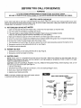
BEFORE YOU CALL FOR SERVICE
WARNING
-
/
TO GUARD AGAINST SEVERE BURNS OR POSSIBLE FATALELECTRICAL SHOCK,
BE SURE TO TURN OFF ELECTRICAL POWER TO THE WATER HEATER BEFORE REMOVING ANY PANELS,
HELPFUL
/
J
HINTS CHECKLIST
If your water heater fails to work right, make the following easy checks. Often, you will find what's wrong yourself and you won't
have to call and wait for service and hot water. If you do not find what's wrong when making the checks, then call for service.
PLEASE READ THE WARRANTY NOTES ON PAGE 16.
A. NOT ENOUGH
OR NO HOT WATER
1. Used more hot water than the water heater holds, or faster than the water heater can heat the water.
2. Hot water wasted through leaking or partially open faucet.
3. If the water heater is newly installed, check the Installation Steps to be sure it's installed correctly
(THIS IS A 240V WATER HEATERAND MUST BE WIRED TO A 240V SUPPLY).
4. Make sure the electrical supply is turned on and that the cold water supply valve is fully open.
5. Check for a blown fuse or popped circuit breaker (circuit breakers weaken with age and may not handle the rated load).
6. During winter months, the colder supply water takes longer to heat.
7. The temperature limitswitch (Page 10) may have opened the circuit ff water temperature reached the maximum limit.
8. Temperature controls for the heating elements set too low (Page 9).
9. Possible burned out element(s).
B. WATER TOO HOT
1. Temperaturecontrolsfor the heatingelements set too high (Page9).
2. Temperaturecontrolthermostat not working.
C. WATER LEAKS
NOTE: Always checkfor condensation first as the source of the "leak". Wipe all wet surfaces dry and check again. Also, the ..,
temperature and pressure relief valve may have opened to vent high pressure or temperature. Points to check on the water '
heater for possibleleaksare as follows.
CAUTION: TURN OFF ELECTRICALPOWER IF YOU WILL REMOVE THE ACCESS PANELS. Before repairinga leak, turn off
the water supply and drain the tank (see Page 10).
1. Inlet and outletfittings.
2. Temperatureand pressure relief valveconnection, or the valve itself(see Pages 4 and 6).
3. Drain valve, or drain valvethreads to tank.
4. Gaskets around heating element(s).
NOTE: Improperly installed heat traps could cause reduCed
or restricted water flow (see Pages 4 and 5).
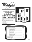
lair] _
HEAT TRAP INSTALLATION
Install on V_ater Heater
inlet (COLD) Side
As Shown
Install on Water Heater
Outlet (HOT} Side
AS Shown
Inse_
Pink In=ert
Water
)irection
Hot Side Trap
Water Flow OirectiQn
1 _ x 3/4" Reducer
(included)
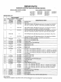
REPAIR PARTS
KENMORE
SINGLE ELEMENT
MODEL NUMBER
SURVIVOR
ELECTRIC
WATER HEATERS
DUAL ELEMENT
MODEL NUMBERS
449.314410
449.310310
449.310311
449.310410
449.310411
449.310510
449.310530
449.310531
449.320310
449.320311
449.320410
449.320411
449.320510
449.320511
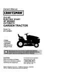
17.
1
NOTE" The above listed Kenmore Survivor water heaters are
shipped with a factory installed Temperature and Pressure Relief
Valve, Key No. 19, and factory installed heat traps, Key No. 20.
\
8
14
13
10
11
\
5
12
J
e"
HEX UNION
NUT
1
2
5
NOTE: TO REMOVE THE DRAIN VALVE OR TO FACE IN A DIFFERENT DIRECTION,
HOLD THE HEX UNION NUT WITH A WRENCH WHILE TURNING THE DRAIN
VALVE. DO NOT TURN THE DRAIN VALVE WITHOUT HOLDING THE HEX UNION
NUT OR YOU WILL DAMAGE THE WATER HEATER BEYOND REPAIR.
14
REPAIR PARTS
KENMORE
SURVIVOR
ELECTRIC
SINGLE ELEMENT MODEL NUMBER
449.314410
DUAL ELEMENT MODEL NUMBERS
449.310310
449.310311
449.310410
449.310411
REPAIR PARTS LIST
WATER HEATERS
449.310510
449.310530
449.310531
449.320310
449.320311
449.320410
449.320411
449.320510
449.320511
PART NUMBERS
KEY
NO.
1
2
3
SINGLE ELEMENT
MODELS
SP 230090
SP 330130
DUAL ELEMENT
MODELS
SP 610140
Upper Heating Element, 5500Wa_ (includes Key No. 9)for ModeI Nos. 449.320310,
449.320311, 449.320410,449.320411,449.320510and
449.320511
Lower He_ing Element, 3800Watt _ncludes Key No. 9)for Medel Nos. 449.310310,
449.310311, 449.310410, 449.310411, 449.310510, 449.310530 and 449.310531
SP 610130
SP 330020
SP 330020
SP 310040
SP 310050
SP 230100
9
SP 310060
10
SP 410842
SP 310010
SP 310020
SP 230100
SP 310060
SP 410843
SP 410844
SP 410845
11
12
13
!4
15
16
17
18
SP 410260
SP 410120
SP 230110
SP 330030
SP 230022
SP
SP
SP
SP
SP
SP
SP
410040
410260
310040
31O030
410120
230110
330030
SP 230023
SP 230024
SP 230025
19
20
&
&
&
42-33075"
42-33094*
SP 212410
42-31923"
SP 330140
Upper Heating Element, 3800 Watt (includes Key No. 9) for Model Nos. 449.310310,
449.310311,449.310410, 449.310411,449.310510, 449.310530 and 449.310531
Lower Heating Element, 3800 Watt (includes Key No. 9) for Model No. 449.314410
SP 610740
6
7
8
OF PART
Seal Ring (3 req.)
Drain Valve
SP 61O67O
5
DESCRIPTION
SP 230090
SP 330130
SP 61013O
42-33075"
42-33094*
SP 212410
42-31923*
SP 330140
Lower Heating Element, 5500 Watt (includes Key No. 9) for Model Nos. 449.320310,
449.320311,449.320410, 449.320411,449.320510 and 449.320511
Screw, #10-16 x 5/8 Tapping (6 req.)
Screw, #10-16 x 5/8 Tapping (10 req.)
Protector (lower)
Temperature Control Thermostat (lower)
Retaining Spring (1 req.)
Retaining Spring (2 req.)
Gasket (1 req.)
Gasket (2 req.)
Front Panel - use on Model No. 449.314410
Front Panel - use on Model Nos. 449.310310, 449.310311,449.320310 and 449.320311
Front Panel - use on Model Nos. 449.310410, 449.310411,449.320410 and 449.320411
Front Panel - use on Model Nos. 449.310510, 449.310530, 449.310531, 449.320510
and 449.320511
Control Box Cover Upper
Control Box Cover Lower
Protector (upper)
Temperature and Control Thermostat (upper)
Junction Box Cover
Seal Ring
Reducer Bushing,
Dip Tube - use on
Dip Tube - use on
Dip Tube - use on
Dip Tube - use on
and 449.320511
1 in. x 3/4 in.
Model No. 449.314410
Model Nos. 449.310310, 449.310311,449.320310 and 449.320311
Model Nos. 449.310410, 449.310411,449.320410 and 449.320411
Model Nos. 449.310510, 449.310530, 449.310531,449.320510
Temperature and Pressure Relief Valve
Hot and Cold Heat Traps
Owners Manual
Element Wrench
VacuumReliefValve(seePages4 and 5 for installationinstructions.)
z_Not illustrated.
* These parts are available in many Sears stores plumbing
departments
15
or can be ordered from Sears Service Centers.
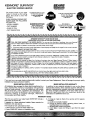
KENMORE ®SURVIVOR
SE=ARS
TM
ELECTRIC WATER HEATER
Ar_w_a's Repair _szs
The model number of your water
heater is found on the rating
decal. This decal is under the
front panel.
WHEN ORDERING REPAIR.PART,
ALWAYS GIVE THE FOLLOWING
INFORMATION:
_-MODEL NUMBER
- PART NUMBER
- NAME OF ITEM
- PART DESCRIPTION
_
For in-home major brand repair service
For the repair or replacement parts you need
Cell24hoursaday,7daysa week
1-800-4-REPAIR
Call7am-7 pm7 daysaweek
1-800-366-PART
(1-g00-473-7247)
(1 -goo-366-727g)
For information oo purchasing a Sears
Maintenance Agreement or to inquire
about an existing Agreement
..,,ram.=
For the location of a
Sears Repair Service Center in your area
Call 24 hours a day, ? days e week
call9 am- 5 prn.M0nday-Saturday
t -800-827-6655
1-800-488-122.2
!
t
KENMORIP SURVIVOR TM WATER HEATER TANK
WARRANTED FOR AS LONG AS YOU OWN YOUR HOME.
FULL ONE YEAR WARRANTY ON WATER HEATER. For one year from the date of purchase, when your Kenmore ®
Survivor TM Water Heater is installed and operated in accordance with the instructions in the Owner's Manual, Sears will:
1. Repair defects in material or workmanship
in this water heater, free of charge.
2. Furnish and install a new current model water heater of equal capacity and quality, free of charge, if a leak occurs in the tank.
LIMITED WARRANTY
ON TANKS THAT LEAK:
For as long as the original purchaser owns the home in which the Kenmore ® Survivor TM Water Heater has been installed, if a
leak occurs in the tank, Sears will furnish a new current model water heater of equal capacity and quality. You will be charged
for installation and labor.
If the home is subsequently sold or the water heater is subject to commercial, institutional, industrial, rental or other non-residential use, the above warranty c_verage for tanks that leak is effective for 15 years from the date of installation.
LIMITED WARRANTY
ON PARTS:
After one year and through five years from the date of purchase, when your Sears Kenmore ® Survivor TM Water Heater is
installed and operated in accordance with the information in this Manual, if a part fails due to a defect in materials or workmanship; Sears will furnish a replacement part free of charge. You will be charged for installation and labor, if the water heater is
subjected to commercial, institutional, industrial, rental, or other non-residential use, the above parts warranty is effective for
one year from date of installation.
TO OBTAIN WARRANTY SERVICE, SIMPLY CONTACT THE NEAREST SEARS STORE OR SEARS SERVICE CENTER [N THE
UNITED STATES.
This warranty gives you specific legal rights and you may also have other rights which vary from state to state.
Sears, Roebuck and Co., D/817 WA, Hoffman Estates, IL 60179
(
If you want your new water heater professionally installed,contact your Sears Salesperson. Sears will arrange for prompt, quality
installationby Sears authorized installers.
SEARS INSTALLATION POLICY
SEARS INSTALLATION WARRANTY
All installation labor arranged by Sears shall be performed in a
In addition to any warranty extended to you on the Sears
neat, workmanlike manner in accordance with generally
merchandise involved, which warranty becomes effective the
accepted trade practices. Further, all installations shall comply
date the merchandise is installed,should the workmanship of
with all local laws, codes, regulations and ordinances. The
any Sears arranged installationprove faulty within one year,
customer shall also be protected, during installation, by
Sears will, upon notice from you, cause such faults to be
insurance
relating to property
damage, Workmen's
corrected at no additional cost to you.
Compensation and Public Liability.
WARRANTY NOTES
The price you paid for your water heater DOES NOT include a
free check-up service call.
If installed by a Sears authorized installer, Sears warrants the
installation work (see above).
If the installer is NOT authorized by Sears ...
1. Sears warranty covers the water heater only.
2. Sears DOES NOT warrant the installation work.
3. A charge is made by Sears for a service call for reasons
including:
a. poorly or incorrectly installed
b. turning on electric power, replacing blown fuses, or
resetting tripped circuit breakers
c. adusting water heater thermostats
d. water leaks in pipe and fittings to and from the water
heater
16