1
Cisco Intrusion Prevention System
Appliance and Module Installation Guide
for IPS 7.1
Americas Headquarters
Cisco Systems, Inc.
170 West Tasman Drive
San Jose, CA 95134-1706
USA
http://www.cisco.com
Tel: 408 526-4000
800 553-NETS (6387)
Fax: 408 527-0883
Text Part Number: OL-24002-01
THE SPECIFICATIONS AND INFORMATION REGARDING THE PRODUCTS IN THIS MANUAL ARE SUBJECT TO CHANGE WITHOUT NOTICE. ALL
STATEMENTS, INFORMATION, AND RECOMMENDATIONS IN THIS MANUAL ARE BELIEVED TO BE ACCURATE BUT ARE PRESENTED WITHOUT
WARRANTY OF ANY KIND, EXPRESS OR IMPLIED. USERS MUST TAKE FULL RESPONSIBILITY FOR THEIR APPLICATION OF ANY PRODUCTS.
THE SOFTWARE LICENSE AND LIMITED WARRANTY FOR THE ACCOMPANYING PRODUCT ARE SET FORTH IN THE INFORMATION PACKET THAT
SHIPPED WITH THE PRODUCT AND ARE INCORPORATED HEREIN BY THIS REFERENCE. IF YOU ARE UNABLE TO LOCATE THE SOFTWARE LICENSE
OR LIMITED WARRANTY, CONTACT YOUR CISCO REPRESENTATIVE FOR A COPY.
The following information is for FCC compliance of Class A devices: This equipment has been tested and found to comply with the limits for a Class A digital device, pursuant
to part 15 of the FCC rules. These limits are designed to provide reasonable protection against harmful interference when the equipment is operated in a commercial
environment. This equipment generates, uses, and can radiate radio-frequency energy and, if not installed and used in accordance with the instruction manual, may cause
harmful interference to radio communications. Operation of this equipment in a residential area is likely to cause harmful interference, in which case users will be required
to correct the interference at their own expense.
The following information is for FCC compliance of Class B devices: This equipment has been tested and found to comply with the limits for a Class B digital device, pursuant
to part 15 of the FCC rules. These limits are designed to provide reasonable protection against harmful interference in a residential installation. This equipment generates,
uses and can radiate radio frequency energy and, if not installed and used in accordance with the instructions, may cause harmful interference to radio communications.
However, there is no guarantee that interference will not occur in a particular installation. If the equipment causes interference to radio or television reception, which can be
determined by turning the equipment off and on, users are encouraged to try to correct the interference by using one or more of the following measures:
•
•
•
•
Reorient or relocate the receiving antenna.
Increase the separation between the equipment and receiver.
Connect the equipment into an outlet on a circuit different from that to which the receiver is connected.
Consult the dealer or an experienced radio/TV technician for help.
Modifications to this product not authorized by Cisco could void the FCC approval and negate your authority to operate the product.
The Cisco implementation of TCP header compression is an adaptation of a program developed by the University of California, Berkeley (UCB) as part of UCB’s public
domain version of the UNIX operating system. All rights reserved. Copyright © 1981, Regents of the University of California.
NOTWITHSTANDING ANY OTHER WARRANTY HEREIN, ALL DOCUMENT FILES AND SOFTWARE OF THESE SUPPLIERS ARE PROVIDED “AS IS” WITH
ALL FAULTS. CISCO AND THE ABOVE-NAMED SUPPLIERS DISCLAIM ALL WARRANTIES, EXPRESSED OR IMPLIED, INCLUDING, WITHOUT
LIMITATION, THOSE OF MERCHANTABILITY, FITNESS FOR A PARTICULAR PURPOSE AND NONINFRINGEMENT OR ARISING FROM A COURSE OF
DEALING, USAGE, OR TRADE PRACTICE.
IN NO EVENT SHALL CISCO OR ITS SUPPLIERS BE LIABLE FOR ANY INDIRECT, SPECIAL, CONSEQUENTIAL, OR INCIDENTAL DAMAGES, INCLUDING,
WITHOUT LIMITATION, LOST PROFITS OR LOSS OR DAMAGE TO DATA ARISING OUT OF THE USE OR INABILITY TO USE THIS MANUAL, EVEN IF CISCO
OR ITS SUPPLIERS HAVE BEEN ADVISED OF THE POSSIBILITY OF SUCH DAMAGES.
Cisco and the Cisco logo are trademarks or registered trademarks of Cisco and/or its affiliates in the U.S. and other countries. To view a list of Cisco trademarks, go to this
URL: www.cisco.com/go/trademarks. Third-party trademarks mentioned are the property of their respective owners. The use of the word partner does not imply a partnership
relationship between Cisco and any other company. (1110R)
Any Internet Protocol (IP) addresses used in this document are not intended to be actual addresses. Any examples, command display output, and figures included in the
document are shown for illustrative purposes only. Any use of actual IP addresses in illustrative content is unintentional and coincidental.
Cisco Intrusion Prevention System Appliance and Module Installation Guide for IPS 7.1
© 2010-2013 Cisco Systems, Inc. All rights reserved.
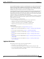
CONTENTS
About This Guide
xiii
Contents
xiii
Audience
xiii
Organization
xiv
Conventions
xiv
Related Documentation
xv
Where to Find Safety and Warning Information
xv
Obtaining Documentation, Using the Cisco Bug Search Tool, and Submitting a Service Request
CHAPTER
1
Introducing the Sensor
Contents
xvi
1-1
1-1
How the Sensor Functions 1-1
Capturing Network Traffic 1-1
Your Network Topology 1-3
Correctly Deploying the Sensor 1-3
Tuning the IPS 1-3
Sensor Interfaces 1-4
Understanding Sensor Interfaces 1-4
Command and Control Interface 1-5
Sensing Interfaces 1-6
Interface Support 1-6
TCP Reset Interfaces 1-11
Interface Restrictions 1-12
Interface Modes 1-14
Promiscuous Mode 1-14
IPv6, Switches, and Lack of VACL Capture
Inline Interface Pair Mode 1-16
Inline VLAN Pair Mode 1-16
VLAN Group Mode 1-17
Deploying VLAN Groups 1-18
Supported Sensors
1-15
1-18
IPS Appliances 1-20
Introducing the IPS Appliance
1-20
Cisco Intrusion Prevention System Appliance Hardware Installation Guide for IPS 7.1
OL-24002-01
iii
Contents
Appliance Restrictions 1-21
Connecting an Appliance to a Terminal Server
1-22
Time Sources and the Sensor 1-22
The Sensor and Time Sources 1-23
Synchronizing IPS Module System Clocks with the Parent Device System Clock
Verifying the Sensor is Synchronized with the NTP Server 1-23
Correcting the Time on the Sensor 1-24
CHAPTER
2
Preparing the Appliance for Installation
Installation Preparation
2-1
2-1
Safety Recommendations 2-2
Safety Guidelines 2-2
Electricity Safety Guidelines 2-2
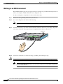
Preventing Electrostatic Discharge Damage
Working in an ESD Environment 2-4
General Site Requirements 2-5
Site Environment 2-5
Preventive Site Configuration
Power Supply Considerations
Configuring Equipment Racks
CHAPTER
3
Installing the IPS 4270-20
Contents
1-23
2-3
2-5
2-6
2-6
3-1
3-1
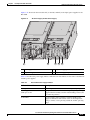
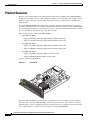
Installation Notes and Caveats
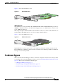
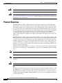
Product Overview
3-1
3-2
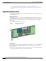
Supported Interface Cards
3-4
Hardware Bypass 3-5
4GE Bypass Interface Card 3-6
Hardware Bypass Configuration Restrictions 3-6
Hardware Bypass and Link Changes and Drops 3-7
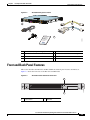
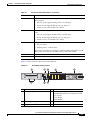
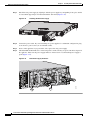
Front and Back Panel Features
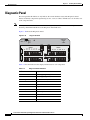
Diagnostic Panel
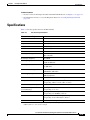
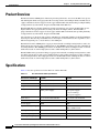
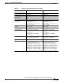
Specifications
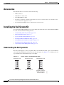
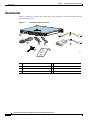
Accessories
3-8
3-14
3-15
3-16
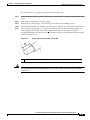
Installing the Rail System Kit 3-16
Understanding the Rail System Kit 3-16
Rail System Kit Contents 3-17
Space and Airflow Requirements 3-17
Cisco Intrusion Prevention System Appliance Hardware Installation Guide for IPS 7.1
iv
OL-24002-01
Contents
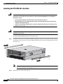
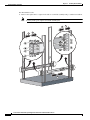
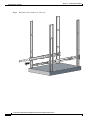
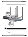
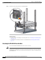
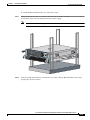
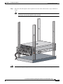
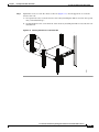
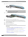
Installing the IPS 4270-20 in the Rack 3-18
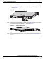
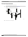
Extending the IPS 4270-20 from the Rack 3-26
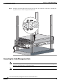
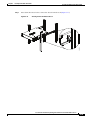
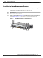
Installing the Cable Management Arm 3-28
Converting the Cable Management Arm 3-32
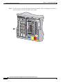
Installing the IPS 4270-20
3-35
Removing and Replacing the Chassis Cover
Accessing the Diagnostic Panel
3-42
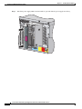
Installing and Removing Interface Cards
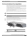
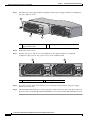
Installing and Removing the Power Supply
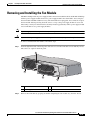
Installing and Removing Fans
4
Installing the IPS 4345 and IPS 4360
Contents
3-43
3-45
3-50
Troubleshooting Loose Connections
CHAPTER
3-39
3-52
4-1
4-1
Installation Notes and Caveats
Product Overview
Specifications
Accessories
4-1
4-2
4-2
4-4
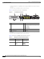
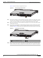
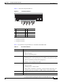
Front and Back Panel Features
4-5
Rack Mount Installation 4-9
Rack-Mounting Guidelines 4-9
Installing the IPS 4345 in a Rack 4-10
Mounting the IPS 4345 and IPS 4360 in a Rack with the Slide Rail Mounting System
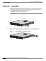
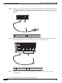
Installing the Appliance on the Network
4-11
4-12
Removing and Installing the Power Supply 4-15
AC Power Supply in V01 and V02 Chassis 4-15
Understanding the Power Supplies 4-16
Removing and Installing the AC Power Supply 4-18
Installing DC Input Power 4-21
Removing and Installing the DC Power Supply 4-26
CHAPTER
5
Installing the IPS 4510 and IPS 4520
Contents
5-1
5-1
Installation Notes and Caveats
Product Overview
5-2
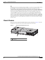
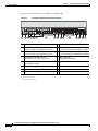
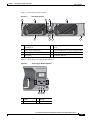
Chassis Features
5-3
Specifications
5-1
5-9
Cisco Intrusion Prevention System Appliance Hardware Installation Guide for IPS 7.1
OL-24002-01
v
Contents
Accessories
5-10
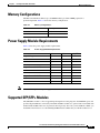
Memory Configurations
5-11
Power Supply Module Requirements
Supported SFP/SFP+ Modules
5-11
5-11
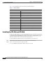
Installing the IPS 4510 and IPS 4520
5-12
Removing and Installing the Core IPS SSP
5-15
Removing and Installing the Power Supply Module
Removing and Installing the Fan Module
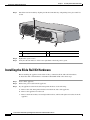
Installing the Slide Rail Kit Hardware
5-17
5-19
5-20
Installing and Removing the Slide Rail Kit 5-21
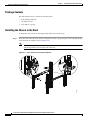
Package Contents 5-22
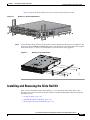
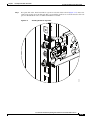
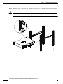
Installing the Chassis in the Rack 5-22
Removing the Chassis from the Rack 5-28
Rack-Mounting the Chassis Using the Fixed Rack Mount
Installing the Cable Management Brackets
Troubleshooting Loose Connections
6
5-33
5-34
IPS 4500 Series Sensors and the SwitchApp
CHAPTER
5-35
Installing and Removing the ASA 5500 AIP SSM
Contents
Product Overview
Specifications
6-1
6-2
6-4
Memory Specifications
6-4
Hardware and Software Requirements
6-4
6-5
Installation and Removal Instructions 6-5
Installing the ASA 5500 AIP SSM 6-5
Verifying the Status of the ASA 5500 AIP SSM
Removing the ASA 5500 AIP SSM 6-7
CHAPTER
7
Installing and Removing the ASA 5585-X IPS SSP
Contents
6-1
6-1
Installation Notes and Caveats
Indicators
5-30
6-7
7-1
7-1
Installation Notes and Caveats
7-1
Introducing the ASA 5585-X IPS SSP
Specifications
7-2
7-3
Cisco Intrusion Prevention System Appliance Hardware Installation Guide for IPS 7.1
vi
OL-24002-01
Contents
Hardware and Software Requirements
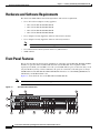
Front Panel Features
7-4
Memory Requirements
SFP/SFP+ Modules
7-4
7-8
7-9
Installing the ASA 5585-X IPS SSP
Installing SFP/SFP+ Modules
7-9
7-11
Verifying the Status of the ASA 5585-X IPS SSP
7-12
Removing and Replacing the ASA 5585-X IPS SSP
APPENDIX
A
Logging In to the Sensor
Contents
A-1
A-1
Supported User Roles
A-1
Logging In to the Appliance
A-2
Connecting an Appliance to a Terminal Server
Logging In to the ASA 5500 AIP SSP
B
A-5
Logging In to the ASA 5585-X IPS SSP
A-6
Initializing the Sensor
Contents
A-3
A-4
Logging In to the ASA 5500-X IPS SSP
Logging In to the Sensor
APPENDIX
7-13
A-7
B-1
B-1
Understanding Initialization
Simplified Setup Mode
B-2
System Configuration Dialog
Basic Sensor Setup
B-1
B-2
B-4
Advanced Setup B-7
Advanced Setup for the Appliance B-7
Advanced Setup for the ASA 5500 AIP SSM B-13
Advanced Setup for the ASA 5500-X IPS SSP B-17
Advanced Setup for the ASA 5585-X IPS SSP B-21
Verifying Initialization
APPENDIX
C
Obtaining Software
Contents
B-25
C-1
C-1
Obtaining Cisco IPS Software
IPS 7.1 Files
C-1
C-2
Cisco Intrusion Prevention System Appliance Hardware Installation Guide for IPS 7.1
OL-24002-01
vii
Contents
IPS Software Versioning
C-3
IPS Software Release Examples
Accessing IPS Documentation
C-5
C-7
Cisco Security Intelligence Operations
C-7
Obtaining a License Key From Cisco.com C-8
Understanding Licensing C-8
Service Programs for IPS Products C-9
Obtaining and Installing the License Key Using the IDM or the IME
Obtaining and Installing the License Key Using the CLI C-11
Obtaining a License for the IPS 4270-20 C-13
Licensing the ASA 5500-X IPS SSP C-14
Uninstalling the License Key C-14
APPENDIX
D
Upgrading, Downgrading, and Installing System Images
Contents
C-10
D-1
D-1
System Image Notes and Caveats
D-1
Upgrades, Downgrades, and System Images
Supported FTP and HTTP/HTTPS Servers
D-2
D-3
Upgrading the Sensor D-3
IPS 7.1 Upgrade Files D-3
Upgrade Notes and Caveats D-4
Manually Upgrading the Sensor D-4
Upgrading the Recovery Partition D-6
Configuring Automatic Upgrades D-7
Understanding Automatic Upgrades D-8
Automatically Upgrading the Sensor D-8
Downgrading the Sensor
D-11
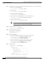
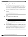
Recovering the Application Partition
D-12
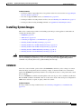
Installing System Images D-13
ROMMON D-13
TFTP Servers D-14
Connecting an Appliance to a Terminal Server D-14
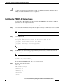
Installing the IPS 4270-20 System Image D-15
Installing the IPS 4345 and IPS 4360 System Images D-17
Installing the IPS 4510 and IPS 4520 System Image D-20
Installing the ASA 5500-X IPS SSP System Image D-23
Installing the ASA 5585-X IPS SSP System Image D-24
Installing the ASA 5585-X IPS SSP System Image Using the hw-module Command
D-25
Cisco Intrusion Prevention System Appliance Hardware Installation Guide for IPS 7.1
viii
OL-24002-01
Contents
Installing the ASA 5585-X IPS SSP System Image Using ROMMON
APPENDIX
E
Troubleshooting
Contents
D-27
E-1
E-1
Cisco Bug Search
E-2
Preventive Maintenance E-2
Understanding Preventive Maintenance E-2
Creating and Using a Backup Configuration File E-3
Backing Up and Restoring the Configuration File Using a Remote Server
Creating the Service Account E-5
Disaster Recovery
E-3
E-6
Recovering the Password E-7
Understanding Password Recovery E-8
Recovering the Password for the Appliance E-8
Using the GRUB Menu E-8
Using ROMMON E-9
Recovering the ASA 5500-X IPS SSP Password E-10
Recovering the ASA 5585-X IPS SSP Password E-12
Disabling Password Recovery E-13
Verifying the State of Password Recovery E-14
Troubleshooting Password Recovery E-15
Time Sources and the Sensor E-15
Time Sources and the Sensor E-15
Synchronizing IPS Module Clocks with Parent Device Clocks E-16
Verifying the Sensor is Synchronized with the NTP Server E-16
Correcting Time on the Sensor E-17
Advantages and Restrictions of Virtualization
Supported MIBs
E-17
E-18
When to Disable Anomaly Detection
Troubleshooting Global Correlation
Analysis Engine Not Responding
E-19
E-19
E-20
Troubleshooting RADIUS Authentication
E-21
Troubleshooting External Product Interfaces E-21
External Product Interfaces Issues E-21
External Product Interfaces Troubleshooting Tips
E-22
Troubleshooting the Appliance E-22
The Appliance and Jumbo Packet Frame Size E-23
Hardware Bypass and Link Changes and Drops E-23
Cisco Intrusion Prevention System Appliance Hardware Installation Guide for IPS 7.1
OL-24002-01
ix
Contents
Troubleshooting Loose Connections E-24
Analysis Engine is Busy E-24
Communication Problems E-25
Cannot Access the Sensor CLI Through Telnet or SSH E-25
Correcting a Misconfigured Access List E-27
Duplicate IP Address Shuts Interface Down E-28
The SensorApp and Alerting E-29
The SensorApp Is Not Running E-29
Physical Connectivity, SPAN, or VACL Port Issue E-31
Unable to See Alerts E-32
Sensor Not Seeing Packets E-34
Cleaning Up a Corrupted SensorApp Configuration E-35
Blocking E-36
Troubleshooting Blocking E-36
Verifying ARC is Running E-37
Verifying ARC Connections are Active E-38
Device Access Issues E-40
Verifying the Interfaces and Directions on the Network Device E-41
Blocking Not Occurring for a Signature E-42
Verifying the Master Blocking Sensor Configuration E-43
Logging E-45
Enabling Debug Logging E-45
Zone Names E-49
Directing cidLog Messages to SysLog E-50
TCP Reset Not Occurring for a Signature E-51
Software Upgrades E-52
Upgrading and Analysis Engine E-52
Which Updates to Apply and Their Prerequisites E-53
Issues With Automatic Update E-53
Updating a Sensor with the Update Stored on the Sensor E-54
Troubleshooting the IDM E-55
Cannot Launch IDM - Loading Java Applet Failed E-55
Cannot Launch the IDM-the Analysis Engine Busy E-56
The IDM, Remote Manager, or Sensing Interfaces Cannot Access the Sensor
Signatures Not Producing Alerts E-57
Troubleshooting the IME E-57
Time Synchronization on the IME and the Sensor
Not Supported Error Message E-58
Installation Error E-58
E-56
E-58
Cisco Intrusion Prevention System Appliance Hardware Installation Guide for IPS 7.1
x
OL-24002-01
Contents
Troubleshooting the ASA 5500 AIP SSM E-59
Health and Status Information E-59
Failover Scenarios E-61
The ASA 5500 AIP SSM and the Normalizer Engine E-62
The ASA 5500 AIP SSM and the Data Plane E-63
The ASA 5500 AIP SSM and Jumbo Packet Frame Size E-63
The ASA 5500 AIP SSM and Jumbo Packets E-63
TCP Reset Differences Between IPS Appliances and ASA IPS Modules
IPS Reloading Messages E-64
Troubleshooting the ASA 5500-X IPS SSP E-64
Failover Scenarios E-65
Health and Status Information E-66
The ASA 5500-X IPS SSP and the Normalizer Engine E-67
The ASA 5500-X IPS SSP and Memory Usage E-68
The ASA 5500-X IPS SSP and Jumbo Packet Frame Size E-69
The ASA 5500-X IPS SSP and Jumbo Packets E-69
TCP Reset Differences Between IPS Appliances and ASA IPS Modules
IPS Reloading Messages E-70
IPS Not Loading E-70
E-64
E-69
Troubleshooting the ASA 5585-X IPS SSP E-70
Failover Scenarios E-71
Traffic Flow Stopped on IPS Switchports E-72
Health and Status Information E-72
The ASA 5585-X IPS SSP and the Normalizer Engine E-75
The ASA 5585-X IPS SSP and Jumbo Packet Frame Size E-76
The ASA 5585-X IPS SSP and Jumbo Packets E-76
IPS Reloading Messages E-77
Gathering Information E-77
Health and Network Security Information E-77
Tech Support Information E-78
Understanding the show tech-support Command E-78
Displaying Tech Support Information E-79
Tech Support Command Output E-80
Version Information E-82
Understanding the show version Command E-82
Displaying Version Information E-83
Statistics Information E-85
Understanding the show statistics Command E-85
Displaying Statistics E-86
Cisco Intrusion Prevention System Appliance Hardware Installation Guide for IPS 7.1
OL-24002-01
xi
Contents
Interfaces Information E-97
Understanding the show interfaces Command E-97
Interfaces Command Output E-98
Events Information E-98
Sensor Events E-99
Understanding the show events Command E-99
Displaying Events E-99
Clearing Events E-102
cidDump Script E-102
Uploading and Accessing Files on the Cisco FTP Site E-103
APPENDIX
F
Cable Pinouts
Contents
F-1
F-1
10/100BaseT and 10/100/1000BaseT Connectors
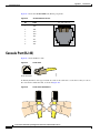
Console Port (RJ-45)
F-1
F-2
RJ-45 to DB-9 or DB-25
F-3
GLOSSARY
INDEX
Cisco Intrusion Prevention System Appliance Hardware Installation Guide for IPS 7.1
xii
OL-24002-01
About This Guide
Published: March 31, 2010
Revised: October 17, 2014, OL-24002-01
Contents
This guide describes how to install appliances and modules that support Cisco IPS 7.1. It includes a
glossary that contains expanded acronyms and pertinent IPS terms. It is part of the documentation set
for Cisco Intrusion Prevention System 7.1. Use this guide in conjunction with the documents listed in
Related Documentation, page xv.
This preface contains the following topics:
•
Audience, page xiii
•
Organization, page xiv
•
Conventions, page xiv
•
Related Documentation, page xv
•
Where to Find Safety and Warning Information, page xv
•
Obtaining Documentation, Using the Cisco Bug Search Tool, and Submitting a Service Request,
page xvi
Audience
This guide is for experienced network security administrators who install and maintain Cisco IPS
sensors, including the supported IPS appliances and modules.
Cisco Intrusion Prevention System Appliance Hardware Installation Guide for IPS 7.1
OL-24002-01
-xiii
Chapter
Contents
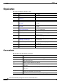
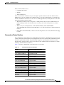
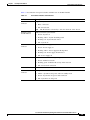
Organization
This guide includes the following sections:
Section
Title
Description
1
“Introducing the Sensor”
Describes IPS appliances and modules.
2
“Preparing the Appliance for
Installation”
Describes how to prepare to install appliances.
3
“Installing the IPS 4270-20”
Describes how to install the IPS 4270-20.
4
“Installing the IPS 4345 and
IPS 4360”
Describes how to install the IPS 4345 and the
IPS 4360.
5
“Installing the IPS 4510 and
IPS 4520”
Describes how to install the IPS 4510 and the
IPS 4520.
6
“Installing and Removing the
ASA 5585-X IPS SSP”
Describes how to install the
ASA 5585-X IPS SSP.
A
“Logging In to the Sensor”
Describes how to log in to the various sensors.
B
“Initializing the Sensor”
Describes how to use the setup command to
initialize sensors.
C
“Obtaining Software”
Describes where to go to get the latest IPS
software and describes the naming conventions.
D
“Upgrading, Downgrading, and
Installing System Images”
Describes how to upgrade sensors and reimage the
various sensors.
E
“Troubleshooting”
Contains troubleshooting tips for IPS hardware
and software.
F
“Cable Pinouts”
Describes the appliance cable pinouts.
“Glossary”
Contains IPS acronyms and terms.
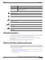
Conventions
This document uses the following conventions:
Convention
Indication
bold font
Commands and keywords and user-entered text appear in bold font.
italic font
Document titles, new or emphasized terms, and arguments for which you supply
values are in italic font.
[ ]
Elements in square brackets are optional.
{x | y | z }
Required alternative keywords are grouped in braces and separated by
vertical bars.
[x|y|z]
Optional alternative keywords are grouped in brackets and separated by
vertical bars.
string
A nonquoted set of characters. Do not use quotation marks around the string or
the string will include the quotation marks.
courier
font
Terminal sessions and information the system displays appear in courier font.
Cisco Intrusion Prevention System Appliance Hardware Installation Guide for IPS 7.1
-xiv
OL-24002-01
Chapter
Contents
< >
Nonprinting characters such as passwords are in angle brackets.
[ ]
Default responses to system prompts are in square brackets.
!, #
An exclamation point (!) or a pound sign (#) at the beginning of a line of code
indicates a comment line.
Note
Means reader take note.
Tip
Means the following information will help you solve a problem.
Caution
Timesaver
Warning
Means reader be careful. In this situation, you might perform an action that could result in equipment
damage or loss of data.
Means the described action saves time. You can save time by performing the action described in
the paragraph.
Means reader be warned. In this situation, you might perform an action that could result in
bodily injury.
Related Documentation
For a complete list of the Cisco IPS 7.1 documentation and where to find it, refer to the following URL:
http://www.cisco.com/en/US/docs/security/ips/7.1/roadmap/19889_01.html
For a complete list of the Cisco ASA 5500 series documentation and where to find it, refer to the
following URL:
http://www.cisco.com/en/US/docs/security/asa/roadmap/asaroadmap.html
Where to Find Safety and Warning Information
Before installing IPS sensors, read the regulatory compliance and safety information documents. These
documents contain important safety information, such as the international agency compliance and safety
information for the sensor. It also includes translations of the safety warnings. The following documents
apply to the sensors in this document:
•
Regulatory Compliance and Safety Information for the Cisco ASA 5500-X Series Appliances and the
Intrusion Prevention System 4300 Series Appliances
•
Regulatory Compliance and Safety Information for the Cisco Intrusion Prevention System 4500
Series Appliance Sensor
Cisco Intrusion Prevention System Appliance Hardware Installation Guide for IPS 7.1
OL-24002-01
-xv
Chapter
Contents
Obtaining Documentation, Using the Cisco Bug Search Tool, and
Submitting a Service Request
For information on obtaining documentation, using the Cisco Bug Search Tool (BST), submitting a
service request, and gathering additional information, see What’s New in Cisco Product Documentation
at: http://www.cisco.com/en/US/docs/general/whatsnew/whatsnew.html.
Subscribe to What’s New in Cisco Product Documentation, which lists all new and revised Cisco technical
documentation, as an RSS feed and deliver content directly to your desktop using a reader application. The
RSS feeds are a free service.
Cisco Intrusion Prevention System Appliance Hardware Installation Guide for IPS 7.1
-xvi
OL-24002-01
CH APT ER
1
Introducing the Sensor
Contents
This chapter introduces the sensor and provides information you should know before you install the
sensor. In this guide, the term sensor refers to all models unless noted otherwise. For a complete list of
supported sensors and their model numbers, see Supported Sensors, page 1-18.
This chapter contains the following sections:
•
How the Sensor Functions, page 1-1
•
Supported Sensors, page 1-18
•
IPS Appliances, page 1-20
•
Time Sources and the Sensor, page 1-22
How the Sensor Functions
This section describes how the sensor functions, and contains the following topics:
•
Capturing Network Traffic, page 1-1
•
Your Network Topology, page 1-3
•
Correctly Deploying the Sensor, page 1-3
•
Tuning the IPS, page 1-3
•
Sensor Interfaces, page 1-4
•
Interface Modes, page 1-14
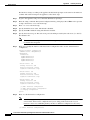
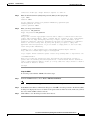
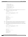
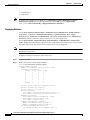
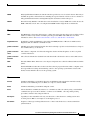
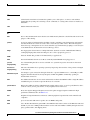
Capturing Network Traffic
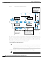
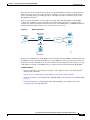
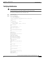
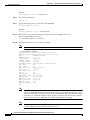
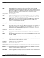
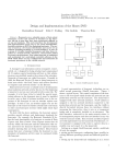
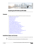
The sensor can operate in either promiscuous or inline mode. Figure 1-1 on page 1-2 shows how you can
deploy a combination of sensors operating in both inline (IPS) and promiscuous (IDS) modes to protect
your network.
Cisco Intrusion Prevention System Appliance Hardware Installation Guide for IPS 7.1
OL-24002-01
1-1
Chapter 1
Introducing the Sensor
How the Sensor Functions
Figure 1-1
Comprehensive Deployment Solutions
Public services segment
Multiple IPS sensors
deliver a highly scalable,
load-balanced solution
via Cisco Etherchannel
technology on Cisco
Catalyst Switches
Attacker
Sensor deployed
in IDS mode
Sensor deployed
in IPS mode
Main campus
Internet
Sensor deployed
in IPS mode
Sensor deployed
in IPS mode
Campus core
148416
Service provider,
partner, or branch
office network
Sensor deployed in hybrid
mode to deliver IDS services
outside router and IPS
services inside the firewall
The command and control interface is always Ethernet. This interface has an assigned IP address, which
allows it to communicate with the manager workstation or network devices (Cisco switches, routers, and
firewalls). Because this interface is visible on the network, you should use encryption to maintain data
privacy. SSH is used to protect the CLI and TLS/SSL is used to protect the manager workstation. SSH
and TLS/SSL are enabled by default on the manager workstations.
When responding to attacks, the sensor can do the following:
•
Insert TCP resets via the sensing interface.
Note
•
You should select the TCP reset action only on signatures associated with a TCP-based
service. If selected as an action on non-TCP-based services, no action is taken. Additionally,
TCP resets are not guaranteed to tear down an offending session because of limitations in
the TCP protocol.
Make ACL changes on switches, routers, and firewalls that the sensor manages.
Note
ACLs may block only future traffic, not current traffic.
Cisco Intrusion Prevention System Appliance Hardware Installation Guide for IPS 7.1
1-2
OL-24002-01
Chapter 1
Introducing the Sensor
How the Sensor Functions
•
Generate IP session logs, session replay, and trigger packets display.
IP session logs are used to gather information about unauthorized use. IP log files are written when
events occur that you have configured the appliance to look for.
•
Implement multiple packet drop actions to stop worms and viruses.
Your Network Topology
Before you deploy and configure your sensors, you should understand the following about your network:
•
The size and complexity of your network.
•
Connections between your network and other networks (and the Internet).
•
The amount and type of network traffic on your network.
This knowledge will help you determine how many sensors are required, the hardware configuration for
each sensor (for example, the size and type of network interface cards), and how many managers are
needed.
Correctly Deploying the Sensor
You should always position the IPS sensor behind a perimeter-filtering device, such as a firewall or
adaptive security appliance. The perimeter device filters traffic to match your security policy thus
allowing acceptable traffic in to your network. Correct placement significantly reduces the number of
alerts, which increases the amount of actionable data you can use to investigate security violations. If
you position the IPS sensor on the edge of your network in front of a firewall, your sensor will produce
alerts on every single scan and attempted attack even if they have no significance to your network
implementation. You will receive hundreds, thousands, or even millions of alerts (in a large enterprise
environment) that are not really critical or actionable in your environment. Analyzing this type of data
is time consuming and costly.
Tuning the IPS
Tuning the IPS ensures that the alerts you see reflect true actionable information. Without tuning the IPS,
it is difficult to do security research or forensics on your network because you will have thousands of
benign events, also known as false positives. False positives are a by-product of all IPS devices, but they
occur much less frequently in Cisco IPS devices since Cisco IPS devices are stateful, normalized, and
use vulnerability signatures for attack evaluation. Cisco IPS devices also provide risk rating, which
identifies high risk events, and policy-based management, which lets you deploy rules to enforce IPS
signature actions based on risk rating.
Follow these tips when tuning your IPS sensors:
•
Place your sensor on your network behind a perimeter-filtering device. Proper sensor placement can
reduce the number of alerts you need to examine by several thousands a day.
•
Deploy the sensor with the default signatures in place.
The default signature set provides you with a very high security protection posture. The Cisco
signature team has spent many hours on testing the defaults to give your sensor the highest
protection. If you think that you have lost these defaults, you can restore them.
•
Make sure that the event action override is set to drop packets with a risk rating greater than 90. This
is the default and ensures that high risk alerts are stopped immediately.
Cisco Intrusion Prevention System Appliance Hardware Installation Guide for IPS 7.1
OL-24002-01
1-3
Chapter 1
Introducing the Sensor
How the Sensor Functions
•
Filter out known false positives caused by specialized software, such as vulnerability scanner and
load balancers by one of the following methods:
– You can configure the sensor to ignore the alerts from the IP addresses of the scanner and load
balancer.
– You can configure the sensor to allow these alerts and then use the IME to filter out the false
positives.
•
Filter the Informational alerts.
These low priority events notifications could indicate that another device is doing reconnaissance
on a device protected by the IPS. Research the source IP addresses from these Informational alerts
to determine what the source is.
•
Analyze the remaining actionable alerts:
– Research the alert.
– Fix the attack source.
– Fix the destination host.
– Modify the IPS policy to provide more information.
For More Information
•
For a detailed description of risk rating, refer to Calculating the Risk Rating.
•
For information on Cisco signatures, for the IDM and IME refer to Defining Signatures, and for the
CLI refer to Defining Signatures.
•
For detailed information on event action overrides, for the IDM and IME refer to Configuring Event
Action Overrides, and for the CLI, refer to Configuring Event Action Overrides.
Sensor Interfaces
This section describes the sensor interfaces, and contains the following topics:
•
Understanding Sensor Interfaces, page 1-4
•
Command and Control Interface, page 1-5
•
Sensing Interfaces, page 1-6
•
Interface Support, page 1-6
•
TCP Reset Interfaces, page 1-11
•
Interface Restrictions, page 1-12
Understanding Sensor Interfaces
The sensor interfaces are named according to the maximum speed and physical location of the interface.
The physical location consists of a port number and a slot number. All interfaces that are built-in on the
sensor motherboard are in slot 0, and the interface card expansion slots are numbered beginning with
slot 1 for the bottom slot with the slot numbers increasing from bottom to top (except for the
IPS 4270-20, where the ports are numbered from top to bottom). Each physical interface can be divided
in to VLAN group subinterfaces, each of which consists of a group of VLANs on that interface.
Cisco Intrusion Prevention System Appliance Hardware Installation Guide for IPS 7.1
1-4
OL-24002-01
Chapter 1
Introducing the Sensor
How the Sensor Functions
There are three interface roles:
•
Command and control
•
Sensing
•
Alternate TCP reset
There are restrictions on which roles you can assign to specific interfaces and some interfaces have
multiple roles. You can configure any sensing interface to any other sensing interface as its TCP reset
interface. The TCP reset interface can also serve as an IDS (promiscuous) sensing interface at the same
time. The following restrictions apply:
•
The TCP reset interface that is assigned to a sensing interface has no effect in inline interface or
inline VLAN pair mode, because TCP resets are always sent on the sensing interfaces in those
modes.
•
There is only one sensing interface on the ASA IPS modules (ASA 5500 AIP SSM,
ASA 5500-X IPS SSP and ASA 5585-X IPS SSP), so you cannot designate an alternate TCP reset
interface.
•
On the IPS 4510 and IPS 4520, no interface-related configurations are allowed when the SensorApp
is down.
Command and Control Interface
The command and control interface has an IP address and is used for configuring the sensor. It receives
security and status events from the sensor and queries the sensor for statistics. The command and control
interface is permanently enabled. It is permanently mapped to a specific physical interface, which
depends on the specific model of sensor. You cannot use the command and control interface as either a
sensing or alternate TCP reset interface.
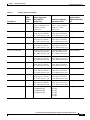
Table 1-1 lists the command and control interfaces for each sensor.
Table 1-1
Command and Control Interfaces
Sensor
Command and Control Interface
ASA 5500 AIP SSM-10
GigabitEthernet 0/0
ASA 5500 AIP SSM-20
GigabitEthernet 0/0
ASA 5500 AIP SSM-40
GigabitEthernet 0/0
ASA 5512-X IPS SSP
Management 0/0
ASA 5515-X IPS SSP
Management 0/0
ASA 5525-X IPS SSP
Management 0/0
ASA 5545-X IPS SSP
Management 0/0
ASA 5555-X IPS SSP
Management 0/0
ASA 5585-X IPS SSP-10
Management 0/0
ASA 5585-X IPS SSP-20
Management 0/0
ASA 5585-X IPS SSP-40
Management 0/0
ASA 5585-X IPS SSP-60
Management 0/0
IPS 4240
Management 0/0
IPS 4255
Management 0/0
Cisco Intrusion Prevention System Appliance Hardware Installation Guide for IPS 7.1
OL-24002-01
1-5
Chapter 1
Introducing the Sensor
How the Sensor Functions
Table 1-1
Command and Control Interfaces (continued)
Sensor
Command and Control Interface
IPS 4260
Management 0/0
IPS 4270-20
Management 0/0
IPS 4345
Management 0/0
IPS 4360
Management 0/0
IPS 4510
Management 0/01
IPS 4520
Management 0/01
1. The 4500 series sensors have two management ports, Management 0/0 and
Management 0/1, but Management 0/1 is reserved for future use.
Sensing Interfaces
Sensing interfaces are used by the sensor to analyze traffic for security violations. A sensor has one or
more sensing interfaces depending on the sensor. Sensing interfaces can operate individually in
promiscuous mode or you can pair them to create inline interfaces.
Note
On appliances, all sensing interfaces are disabled by default. You must enable them to use them. On
modules, the sensing interfaces are permanently enabled.
Some appliances support optional interface cards that add sensing interfaces to the sensor. You must
insert or remove these optional cards while the sensor is powered off. The sensor detects the addition or
removal of a supported interface card. If you remove an optional interface card, some of the interface
configuration is deleted, such as the speed, duplex, description string, enabled/disabled state of the
interface, and any inline interface pairings. These settings are restored to their default settings when the
card is reinstalled. However, the assignment of promiscuous and inline interfaces to the Analysis Engine
is not deleted from the Analysis Engine configuration, but is ignored until those cards are reinserted and
you create the inline interface pairs again.
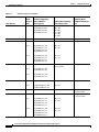
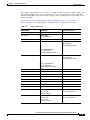
Interface Support
Table 1-2 describes the interface support for appliances and modules running Cisco IPS.
Table 1-2
Interface Support
Interfaces Not
Supporting Inline
(Command and Control
Port)
Base Chassis
Added
Interface
Cards
Interfaces Supporting
Inline VLAN Pairs
(Sensing Ports)
Combinations Supporting
Inline Interface Pairs
ASA 5500 AIP SSM-10
—
GigabitEthernet 0/1 by
security context instead of
VLAN pair or inline
interface pair
GigabitEthernet 0/1 by
security context instead of
VLAN pair or inline
interface pair
GigabitEthernet 0/0
ASA 5500 AIP SSM-20
—
GigabitEthernet 0/1 by
security context instead of
VLAN pair or inline
interface pair
GigabitEthernet 0/1 by
security context instead of
VLAN pair or inline
interface pair
GigabitEthernet 0/0
Cisco Intrusion Prevention System Appliance Hardware Installation Guide for IPS 7.1
1-6
OL-24002-01
Chapter 1
Introducing the Sensor
How the Sensor Functions
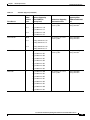
Table 1-2
Interface Support (continued)
Interfaces Not
Supporting Inline
(Command and Control
Port)
Base Chassis
Added
Interface
Cards
Interfaces Supporting
Inline VLAN Pairs
(Sensing Ports)
Combinations Supporting
Inline Interface Pairs
ASA 5500 AIP SSM-40
—
GigabitEthernet 0/1 by
security context instead of
VLAN pair or inline
interface pair
GigabitEthernet 0/1 by
security context instead of
VLAN pair or inline
interface pair
ASA 5512-X IPS SSP
—
PortChannel 0/0 by security PortChannel 0/0 by security Management 0/0
context instead of VLAN
context instead of VLAN
pair or inline interface pair pair or inline interface pair
ASA 5515-X IPS SSP
—
PortChannel 0/0 by security PortChannel 0/0 by security Management 0/0
context instead of VLAN
context instead of VLAN
pair or inline interface pair pair or inline interface pair
ASA 5525-X IPS SSP
—
PortChannel 0/0 by security PortChannel 0/0 by security Management 0/0
context instead of VLAN
context instead of VLAN
pair or inline interface pair pair or inline interface pair
ASA 5545-X IPS SSP
—
PortChannel 0/0 by security PortChannel 0/0 by security Management 0/0
context instead of VLAN
context instead of VLAN
pair or inline interface pair pair or inline interface pair
ASA 5555-X IPS SSP
—
PortChannel 0/0 by security PortChannel 0/0 by security Management 0/0
context instead of VLAN
context instead of VLAN
pair or inline interface pair pair or inline interface pair
ASA 5585-X IPS SSP-10
—
PortChannel 0/0 by security PortChannel 0/0 by security Management 0/0
context instead of VLAN
context instead of VLAN
pair or inline interface pair pair or inline interface pair
ASA 5585-X IPS SSP-20
—
PortChannel 0/0 by security PortChannel 0/0 by security Management 0/0
context instead of VLAN
context instead of VLAN
pair or inline interface pair pair or inline interface pair
ASA 5585-X IPS SSP-40
—
PortChannel 0/0 by security PortChannel 0/0 by security Management 0/0
context instead of VLAN
context instead of VLAN
pair or inline interface pair pair or inline interface pair
ASA 5585-X IPS SSP-60
—
PortChannel 0/0 by security PortChannel 0/0 by security Management 0/0
context instead of VLAN
context instead of VLAN
pair or inline interface pair pair or inline interface pair
IPS 4240
—
GigabitEthernet 0/0
GigabitEthernet 0/1
GigabitEthernet 0/2
GigabitEthernet 0/3
0/0<->0/1
0/0<->0/2
0/0<->0/3
0/1<->0/2
0/1<->0/3
0/2<->0/3
GigabitEthernet 0/0
Management 0/0
Cisco Intrusion Prevention System Appliance Hardware Installation Guide for IPS 7.1
OL-24002-01
1-7
Chapter 1
Introducing the Sensor
How the Sensor Functions
Table 1-2
Interface Support (continued)
Interfaces Not
Supporting Inline
(Command and Control
Port)
Base Chassis
Added
Interface
Cards
Interfaces Supporting
Inline VLAN Pairs
(Sensing Ports)
IPS 4255
—
GigabitEthernet 0/0
GigabitEthernet 0/1
GigabitEthernet 0/2
GigabitEthernet 0/3
0/0<->0/1
0/0<->0/2
0/0<->0/3
0/1<->0/2
0/1<->0/3
0/2<->0/3
Management 0/0
IPS 4260
—
GigabitEthernet 0/1
N/A
Management 0/0
IPS 4260
4GE-BP
GigabitEthernet 0/1
Slot 1
GigabitEthernet 2/0
GigabitEthernet 2/1
GigabitEthernet 2/2
GigabitEthernet 2/3
2/0<->2/11
2/2<->2/3
Slot 2
GigabitEthernet 3/0
GigabitEthernet 3/1
GigabitEthernet 3/2
GigabitEthernet 3/3
3/0<->3/1
3/2<->3/3
2SX
GigabitEthernet 0/1
All sensing ports can be
paired together
Slot 1
GigabitEthernet 2/0
GigabitEthernet 2/1
Slot 2
GigabitEthernet 3/0
GigabitEthernet 3/1
10GE
GigabitEthernet 0/1
Slot 1
TenGigabitEthernet 2/0
TenGigabitEthernet 2/1
2/0<->2/12
IPS 4270-20
—
—
N/A
IPS 4270-20
4GE-BP
IPS 4260
IPS 4260
Combinations Supporting
Inline Interface Pairs
Management 0/0
Management 0/0
Management 0/0
Management 0/0
Management 0/13
Management 0/0
Management 0/14
Slot 1
GigabitEthernet 3/0
GigabitEthernet 3/1
GigabitEthernet 3/2
GigabitEthernet 3/3
3/0<->3/14
3/2<->3/3
Slot 2
GigabitEthernet 4/0
GigabitEthernet 4/1
GigabitEthernet 4/2
GigabitEthernet 4/3
4/0<->4/1
4/2<->4/3
Cisco Intrusion Prevention System Appliance Hardware Installation Guide for IPS 7.1
1-8
OL-24002-01
Chapter 1
Introducing the Sensor
How the Sensor Functions
Table 1-2
Interface Support (continued)
Base Chassis
Added
Interface
Cards
IPS 4270-20
2SX
IPS 4270-20
IPS 4345
Interfaces Supporting
Inline VLAN Pairs
(Sensing Ports)
Slot 1
GigabitEthernet 3/0
GigabitEthernet 3/1
Slot 2
GigabitEthernet 4/0
GigabitEthernet 4/1
10GE
Slot 1
TenGigabitEthernet 5/0
TenGigabitEthernet 5/1
Slot 2
TenGigabitEthernet 7/0
TenGigabitEthernet 7/1
—
GigabitEthernet 0/0
GigabitEthernet 0/1
Combinations Supporting
Inline Interface Pairs
Interfaces Not
Supporting Inline
(Command and Control
Port)
All sensing ports can be
paired together
Management 0/0
Management 0/14
All sensing ports can be
paired together
Management 0/0
Management 0/14
All sensing ports can be
paired together
Management 0/0
Management 0/15
All sensing ports can be
paired together
Management 0/0
Management 0/15
GigabitEthernet 0/2
GigabitEthernet 0/3
GigabitEthernet 0/4
GigabitEthernet 0/5
GigabitEthernet 0/6
GigabitEthernet 0/7
IPS 4360
—
GigabitEthernet 0/0
GigabitEthernet 0/1
GigabitEthernet 0/2
GigabitEthernet 0/3
GigabitEthernet 0/4
GigabitEthernet 0/5
GigabitEthernet 0/6
GigabitEthernet 0/7
Cisco Intrusion Prevention System Appliance Hardware Installation Guide for IPS 7.1
OL-24002-01
1-9
Chapter 1
Introducing the Sensor
How the Sensor Functions
Table 1-2
Interface Support (continued)
Base Chassis
Added
Interface
Cards
Interfaces Supporting
Inline VLAN Pairs
(Sensing Ports)
IPS 4510
—
GigabitEthernet 0/0
GigabitEthernet 0/1
Combinations Supporting
Inline Interface Pairs
Interfaces Not
Supporting Inline
(Command and Control
Port)
All sensing ports can be
paired together
Management 0/0
Management 0/16
All sensing ports can be
paired together
Management 0/0
Management 0/16
GigabitEthernet 0/2
GigabitEthernet 0/3
GigabitEthernet 0/4
GigabitEthernet 0/5
TenGigabitEthernet 0/6
TenGigabitEthernet 0/7
TenGigabitEthernet 0/8
TenGigabitEthernet 0/9
IPS 4520
—TX
GigabitEthernet 0/0
GigabitEthernet 0/1
GigabitEthernet 0/2
GigabitEthernet 0/3
GigabitEthernet 0/4
GigabitEthernet 0/5
TenGigabitEthernet 0/6
TenGigabitEthernet 0/7
TenGigabitEthernet 0/8
TenGigabitEthernet 0/9
1. To disable hardware bypass, pair the interfaces in any other combination (2/0<->2/2 and 2/1<->2/3, for example).
2. To disable hardware bypass, pair the interfaces in any other combination (2/0<->2/2 and 2/1<->2/3, for example).
3. Reserved for future use.
4. To disable hardware bypass, pair the interfaces in any other combination (2/0<->2/2 and 2/1<->2/3, for example).
5. Does not currently support hardware bypass.
6. Reserved for future use.
Note
The IPS 4260 supports a mixture of 4GE-BP, 2SX, and 10GE cards. The IPS 4270-20 supports a mixture
of 4GE-BP, 2SX, and 10GE cards up to a total of either six cards, or sixteen total ports, which ever is
reached first, but is limited to only two 10GE card in the mix of cards.
Cisco Intrusion Prevention System Appliance Hardware Installation Guide for IPS 7.1
1-10
OL-24002-01
Chapter 1
Introducing the Sensor
How the Sensor Functions
TCP Reset Interfaces
This section explains the TCP reset interfaces and when to use them. It contains the following topics:
•
Understanding Alternate TCP Reset Interfaces, page 1-11
•
Designating the Alternate TCP Reset Interface, page 1-12
Understanding Alternate TCP Reset Interfaces
Note
The alternate TCP reset interface setting is ignored in inline interface or inline VLAN pair mode,
because resets are sent inline in these modes.
You can configure sensors to send TCP reset packets to try to reset a network connection between an
attacker host and its intended target host. In some installations when the interface is operating in
promiscuous mode, the sensor may not be able to send the TCP reset packets over the same sensing
interface on which the attack was detected. In such cases, you can associate the sensing interface with
an alternate TCP reset interface and any TCP resets that would otherwise be sent on the sensing interface
when it is operating in promiscuous mode are instead sent out on the associated alternate TCP reset
interface.
If a sensing interface is associated with an alternate TCP reset interface, that association applies when
the sensor is configured for promiscuous mode but is ignored when the sensing interface is configured
for inline mode. any sensing interface can serve as the alternate TCP reset interface for another sensing
interface.
Note
There is only one sensing interface on the ASA IPS modules (ASA 5500 AIP SSM,
ASA 5500-X IPS SSP, and ASA 5585-X IPS SSP), so you cannot designate an alternate TCP reset
interface.
Table 1-3 lists the alternate TCP reset interfaces.
Table 1-3
Alternate TCP Reset Interfaces
Sensor
Alternate TCP Reset Interface
ASA 5500 AIP SSM-10
None
ASA 5500 AIP SSM-20
None
ASA 5500 AIP SSM-40
None
ASA 5512-X IPS SSP
None
ASA 5515-X IPS SSP
None
ASA 5525-X IPS SSP
None
ASA 5545-X IPS SSP
None
ASA 5555-X IPS SSP
None
ASA 5585-X IPS SSP-10
None
ASA 5585-X IPS SSP-20
None
ASA 5585-X IPS SSP-40
None
ASA 5585-X IPS SSP-60
None
Cisco Intrusion Prevention System Appliance Hardware Installation Guide for IPS 7.1
OL-24002-01
1-11
Chapter 1
Introducing the Sensor
How the Sensor Functions
Table 1-3
Alternate TCP Reset Interfaces (continued)
Sensor
Alternate TCP Reset Interface
IPS 4240
Any sensing interface
IPS 4255
Any sensing interface
IPS 4260
Any sensing interface
IPS 4270-20
Any sensing interface
IPS 4345
Any sensing interface
IPS 4360
Any sensing interface
IPS 4510
Any sensing interface
IPS 4520
Any sensing interface
Designating the Alternate TCP Reset Interface
Note
There is only one sensing interface on the ASA IPS modules (ASA 5500 AIP SSM,
ASA 5500-X IPS SSP, and ASA 5585-X IPS SSP), so you cannot designate an alternate TCP reset
interface.
You need to designate an alternate TCP reset interface in the following situations:
Caution
•
When a switch is being monitored with either SPAN or VACL capture and the switch does not accept
incoming packets on the SPAN or VACL capture port.
•
When a switch is being monitored with either SPAN or VACL capture for multiple VLANs, and the
switch does not accept incoming packets with 802.1q headers. The TCP resets need 802.1q headers
to tell which VLAN the resets should be sent on.
•
When a network tap is used for monitoring a connection. Taps do not permit incoming traffic from
the sensor.
You can only assign a sensing interface as an alternate TCP reset interface. You cannot configure the
management interface as an alternate TCP reset interface.
Interface Restrictions
The following restrictions apply to configuring interfaces on the sensor:
•
Physical Interfaces
– In IPS 7.1, rx/tx flow control is disabled on the IPS 4200 series sensors. This is a change from
IPS 7.0 where rx/tx flow control is enabled by default.
– On the ASA IPS modules (ASA 5500 AIP SSM, ASA 5500-X IPS SSP, and
ASA 5585-X IPS SSP) all backplane interfaces have fixed speed, duplex, and state settings.
These settings are protected in the default configuration on all backplane interfaces.
– For nonbackplane FastEthernet interfaces the valid speed settings are 10 Mbps, 100 Mbps, and
auto. Valid duplex settings are full, half, and auto.
Cisco Intrusion Prevention System Appliance Hardware Installation Guide for IPS 7.1
1-12
OL-24002-01
Chapter 1
Introducing the Sensor
How the Sensor Functions
– For Gigabit copper interfaces (1000-TX on the IPS 4240, IPS 4255, IPS 4260, IPS 4270-20,,
IPS 4345, IPS 4360, IPS 4510, and IPS 4520), valid speed settings are 10 Mbps, 100 Mbps,
1000 Mbps, and auto. Valid duplex settings are full, half, and auto.
– For Gigabit (copper or fiber) interfaces, if the speed is configured for 1000 Mbps, the only valid
duplex setting is auto.
– The command and control interface cannot also serve as a sensing interface.
•
Inline Interface Pairs
– Inline interface pairs can contain any combination of sensing interfaces regardless of the
physical interface type (copper versus fiber), speed, or duplex settings of the interface.
However, pairing interfaces of different media type, speeds, and duplex settings may not be
fully tested or supported.
– The command and control interface cannot be a member of an inline interface pair.
– You cannot pair a physical interface with itself in an inline interface pair.
– A physical interface can be a member of only one inline interface pair.
– You can only configure bypass mode and create inline interface pairs on sensor platforms that
support inline mode.
– A physical interface cannot be a member of an inline interface pair unless the subinterface mode
of the physical interface is none.
•
You can configure the ASA IPS modules (ASA 5500 AIP SSM, ASA 5500-X IPS SSP, and
ASA 5585-X IPS SSP) to operate inline even though they have only one sensing interface.
•
Inline VLAN Pairs
– You cannot pair a VLAN with itself.
– You cannot use the default VLAN as one of the paired VLANs in an inline VLAN pair.
– For a given sensing interface, a VLAN can be a member of only one inline VLAN pair.
However, a given VLAN can be a member of an inline VLAN pair on more than one sensing
interface.
– The order in which you specify the VLANs in an inline VLAN pair is not significant.
– A sensing interface in Inline VLAN Pair mode can have from 1 to 255 inline VLAN pairs.
– The ASA IPS modules (ASA 5500 AIP SSM ,ASA 5500-X IPS SSP, and
ASA 5585-X IPS SSP) do not support inline VLAN pairs.
– For the IPS 4510 and IPS 4520, the maximum number of inline VLAN pairs you can create
system wide is 150. On all other platforms, the limit is 255 per interface.
•
Alternate TCP Reset Interface
– You can only assign the alternate TCP reset interface to a sensing interface. You cannot
configure the command and control interface as an alternate TCP reset interface. The alternate
TCP reset interface option is set to none as the default and is protected for all interfaces except
the sensing interfaces.
– You can assign the same physical interface as an alternate TCP reset interface for multiple
sensing interfaces.
– A physical interface can serve as both a sensing interface and an alternate TCP reset interface.
– The command and control interface cannot serve as the alternate TCP reset interface for a
sensing interface.
– A sensing interface cannot serve as its own alternate TCP reset interface.
Cisco Intrusion Prevention System Appliance Hardware Installation Guide for IPS 7.1
OL-24002-01
1-13
Chapter 1
Introducing the Sensor
How the Sensor Functions
– You can only configure interfaces that are capable of TCP resets as alternate TCP reset
interfaces.
– There is only one sensing interface on the ASA IPS modules (ASA 5500 AIP SSM,
ASA 5500-X IPS SSP, and ASA 5585-X IPS SSP), so you cannot designate an alternate TCP
reset interface.
•
VLAN Groups
– You can configure any single interface for promiscuous, inline interface pair, or inline VLAN
pair mode, but no combination of these modes is allowed.
– You cannot add a VLAN to more than one group on each interface.
– You cannot add a VLAN group to multiple virtual sensors.
– An interface can have no more than 255 user-defined VLAN groups.
– When you pair a physical interface, you cannot subdivide it; you can subdivide the pair.
– You can use a VLAN on multiple interfaces; however, you receive a warning for this
configuration.
– You can assign a virtual sensor to any combination of one or more physical interfaces and inline
VLAN pairs, subdivided or not.
– You can subdivide both physical and logical interfaces into VLAN groups.
– The CLI, IDM, and IME prompt you to remove any dangling references. You can leave the
dangling references and continue editing the configuration.
– The CLI, IDM, and IME do not allow configuration changes in Analysis Engine that conflict
with the interface configuration.
– The CLI allows configuration changes in the interface configuration that cause conflicts in the
Analysis Engine configuration. The IDM and IME do not allow changes in the interface
configuration that cause conflicts in the Analysis Engine configuration.
– The ASA IPS modules (ASA 5500 AIP SSM, ASA 5500-X IPS SSP, and
ASA 5585-X IPS SSP) do not support VLAN groups mode.
Interface Modes
The following section describes the interface modes, and contains the following topics:
•
Promiscuous Mode, page 1-14
•
IPv6, Switches, and Lack of VACL Capture, page 1-15
•
Inline Interface Pair Mode, page 1-16
•
Inline VLAN Pair Mode, page 1-16
•
VLAN Group Mode, page 1-17
•
Deploying VLAN Groups, page 1-18
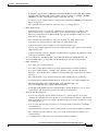
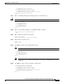
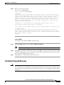
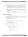
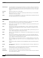
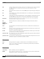
Promiscuous Mode
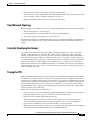
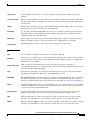
In promiscuous mode, packets do not flow through the sensor. The sensor analyzes a copy of the
monitored traffic rather than the actual forwarded packet. The advantage of operating in promiscuous
mode is that the sensor does not affect the packet flow with the forwarded traffic. The disadvantage of
operating in promiscuous mode, however, is the sensor cannot stop malicious traffic from reaching its
Cisco Intrusion Prevention System Appliance Hardware Installation Guide for IPS 7.1
1-14
OL-24002-01
Chapter 1
Introducing the Sensor
How the Sensor Functions
intended target for certain types of attacks, such as atomic attacks (single-packet attacks). The response
actions implemented by promiscuous sensor devices are post-event responses and often require
assistance from other networking devices, for example, routers and firewalls, to respond to an attack.
While such response actions can prevent some classes of attacks, in atomic attacks the single packet has
the chance of reaching the target system before the promiscuous-based sensor can apply an ACL
modification on a managed device (such as a firewall, switch, or router).
By default, all sensing interfaces are in promiscuous mode. To change an interface from inline interface
mode to promiscuous mode, delete any inline interface that contains that interface and delete any inline
VLAN pair subinterfaces of that interface from the interface configuration.
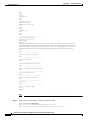
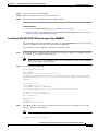
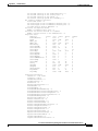
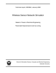
Figure 1-2 illustrates promiscuous mode:
Figure 1-2
Promiscuous Mode
VLAN A
Router
253443
Switch
Host
Span port sending
copies of VLAN A traffic
Sensor
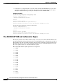
IPv6, Switches, and Lack of VACL Capture
VACLs on Catalyst switches do not have IPv6 support. The most common method for copying traffic to
a sensor configured in promiscuous mode is to use VACL capture. If you want to have IPv6 support, you
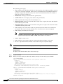
can use SPAN ports.
However, you can only configure up to two monitor sessions on a switch unless you use the following
configuration:
•
Monitor session
•
Multiple trunks to one or more sensors
•
Restrict per trunk port which VLANs are allowed to perform monitoring of many VLANs to more
than two different sensors or virtual sensors within one IPS
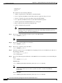
The following configuration uses one SPAN session to send all of the traffic on any of the specified
VLANs to all of the specified ports. Each port configuration only allows a particular VLAN or VLANs
to pass. Thus you can send data from different VLANs to different sensors or virtual sensors all with one
SPAN configuration line:
clear trunk 4/1-4 1-4094
set trunk 4/1 on dot1q 930
set trunk 4/2 on dot1q 932
set trunk 4/3 on dot1q 960
set trunk 4/4 on dot1q 962
set span 930, 932, 960, 962 4/1-4 both
Cisco Intrusion Prevention System Appliance Hardware Installation Guide for IPS 7.1
OL-24002-01
1-15
Chapter 1
Introducing the Sensor
How the Sensor Functions
Note
The SPAN/Monitor configuration is valuable when you want to assign different IPS policies per VLAN
or when you have more bandwidth to monitor than one interface can handle.
For More Information
For more information on promiscuous mode, see Promiscuous Mode, page 1-14.
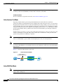
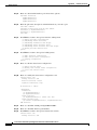
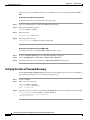
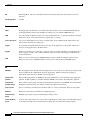
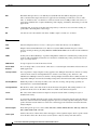
Inline Interface Pair Mode
Operating in inline interface pair mode puts the IPS directly into the traffic flow and affects
packet-forwarding rates making them slower by adding latency. This allows the sensor to stop attacks by
dropping malicious traffic before it reaches the intended target, thus providing a protective service. Not
only is the inline device processing information on Layers 3 and 4, but it is also analyzing the contents
and payload of the packets for more sophisticated embedded attacks (Layers 3 to 7). This deeper analysis
lets the system identify and stop and/or block attacks that would normally pass through a traditional
firewall device.
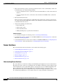
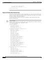
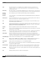
In inline interface pair mode, a packet comes in through the first interface of the pair on the sensor and
out the second interface of the pair. The packet is sent to the second interface of the pair unless that
packet is being denied or modified by a signature.
Note
You can configure the ASA IPS modules (ASA 5500 AIP SSM, ASA 5500-X IPS SSP, and
ASA 5585-X IPS SSP) to operate inline even though they have only one sensing interface.
Note
If the paired interfaces are connected to the same switch, you should configure them on the switch as
access ports with different access VLANs for the two ports. Otherwise, traffic does not flow through the
inline interface.
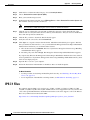
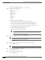
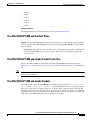
Figure 1-3 illustrates inline interface pair mode:
Figure 1-3
Inline Interface Pair Mode
Traffic passes
through interface pair
Router
Sensor
Switch
253444
VLAN A
Host
Inline VLAN Pair Mode
Note
The ASA IPS modules (ASA 5500 AIP SSM, ASA 5500-X IPS SSP, and ASA 5585-X IPS SSP) do not
support inline VLAN pairs.
Cisco Intrusion Prevention System Appliance Hardware Installation Guide for IPS 7.1
1-16
OL-24002-01
Chapter 1
Introducing the Sensor
How the Sensor Functions
Note
For the IPS 4510 and IPS 4520, the maximum number of inline VLAN pairs you can create systemwide
is 150. On all other platforms, the limit is 255 per interface.
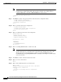
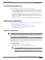
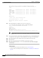
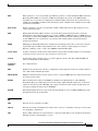
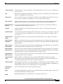
You can associate VLANs in pairs on a physical interface. This is known as inline VLAN pair mode.
Packets received on one of the paired VLANs are analyzed and then forwarded to the other VLAN in the
pair.
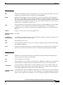
Inline VLAN pair mode is an active sensing mode where a sensing interface acts as an 802.1q trunk port,
and the sensor performs VLAN bridging between pairs of VLANs on the trunk. The sensor inspects the
traffic it receives on each VLAN in each pair, and can either forward the packets on the other VLAN in
the pair, or drop the packet if an intrusion attempt is detected. You can configure an IPS sensor to
simultaneously bridge up to 255 VLAN pairs on each sensing interface. The sensor replaces the
VLAN ID field in the 802.1q header of each received packet with the ID of the egress VLAN on which
the sensor forwards the packet. The sensor drops all packets received on any VLANs that are not
assigned to inline VLAN pairs.
Note
You cannot use the default VLAN as one of the paired VLANs in an inline VLAN pair.
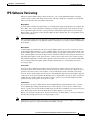
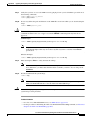
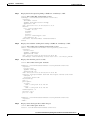
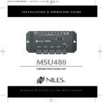
Figure 1-4 illustrates inline VLAN pair mode:
Figure 1-4
Inline VLAN Pair Mode
Switch
253445
VLAN B VLAN A
Router
Host
Trunk port carrying
VLAN A and B
Pairing VLAN A and B
Sensor
VLAN Group Mode
Note
The ASA IPS modules (ASA 5500 AIP SSM, ASA 5500-X IPS SSP, and ASA 5585-X IPS SSP) do not
support VLAN groups mode.
You can divide each physical interface or inline interface into VLAN group subinterfaces, each of which
consists of a group of VLANs on that interface. Analysis Engine supports multiple virtual sensors, each
of which can monitor one or more of these interfaces. This lets you apply multiple policies to the same
sensor. The advantage is that now you can use a sensor with only a few interfaces as if it had many
interfaces.
Note
You cannot divide physical interfaces that are in inline VLAN pairs into VLAN groups.
Cisco Intrusion Prevention System Appliance Hardware Installation Guide for IPS 7.1
OL-24002-01
1-17
Chapter 1
Introducing the Sensor
Supported Sensors
VLAN group subinterfaces associate a set of VLANs with a physical or inline interface. No VLAN can
be a member of more than one VLAN group subinterface. Each VLAN group subinterface is identified
by a number between 1 and 255. Subinterface 0 is a reserved subinterface number used to represent the
entire unvirtualized physical or logical interface. You cannot create, delete, or modify subinterface 0 and
no statistics are reported for it.
An unassigned VLAN group is maintained that contains all VLANs that are not specifically assigned to
another VLAN group. You cannot directly specify the VLANs that are in the unassigned group. When a
VLAN is added to or deleted from another VLAN group subinterface, the unassigned group is updated.
Packets in the native VLAN of an 802.1q trunk do not normally have 802.1q encapsulation headers to
identify the VLAN number to which the packets belong. A default VLAN variable is associated with
each physical interface and you should set this variable to the VLAN number of the native VLAN or to 0.
The value 0 indicates that the native VLAN is either unknown or you do not care if it is specified. If the
default VLAN setting is 0, the following occurs:
Note
•
Any alerts triggered by packets without 802.1q encapsulation have a VLAN value of 0 reported in
the alert.
•
Non-802.1q encapsulated traffic is associated with the unassigned VLAN group and it is not
possible to assign the native VLAN to any other VLAN group.
You can configure a port on a switch as either an access port or a trunk port. On an access port, all traffic
is in a single VLAN is called the access VLAN. On a trunk port, multiple VLANs can be carried over
the port, and each packet has a special header attached called the 802.1q header that contains the VLAN
ID. This header is commonly referred as the VLAN tag. However, a trunk port has a special VLAN called
the native VLAN. Packets in the native VLAN do not have the 802.1q headers attached.
Deploying VLAN Groups
Because a VLAN group of an inline pair does not translate the VLAN ID, an inline paired interface must
exist between two switches to use VLAN groups on a logical interface. For an appliance, you can connect
the two pairs to the same switch, make them access ports, and then set the access VLANs for the two
ports differently. In this configuration, the sensor connects between two VLANs, because each of the
two ports is in access mode and carries only one VLAN. In this case the two ports must be in different
VLANs, and the sensor bridges the two VLANs, monitoring any traffic that flows between the two
VLANs.
You can also connect appliances between two switches. There are two variations. In the first variation,
the two ports are configured as access ports, so they carry a single VLAN. In this way, the sensor bridges
a single VLAN between the two switches.
In the second variation, the two ports are configured as trunk ports, so they can carry multiple VLANs.
In this configuration, the sensor bridges multiple VLANs between the two switches. Because multiple
VLANs are carried over the inline interface pair, the VLANs can be divided into groups and each group
can be assigned to a virtual sensor.
Supported Sensors
Caution
Installing the most recent software on unsupported sensors may yield unpredictable results. We do not
support software installed on unsupported platforms.
Cisco Intrusion Prevention System Appliance Hardware Installation Guide for IPS 7.1
1-18
OL-24002-01
Chapter 1
Introducing the Sensor
Supported Sensors
The currently supported IPS 7.1(x) versions are 7.1(1)E4, 7.1(2)E4, 7.1(3)E4, 7.1(4)E4, 7.1(5)E4, and
IPS 7.1(6)E4. All IPS sensors are not supported in each 7.1(x) version. For a list of the specific IPS
filenames and the IPS versions that each sensor supports, refer to the Release Notes for your IPS version
found at this URL:
http://www.cisco.com/en/US/products/hw/vpndevc/ps4077/prod_release_notes_list.html
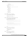
Table 1-4 lists the sensors (IPS appliances and modules) that are supported by Cisco IPS.
Table 1-4
Supported Sensors
Model Name
Part Number
Optional Interfaces
IPS 4240
IPS-4240-K9
IPS-4240-DC-K91
—
—
IPS 4255
IPS-4255-K9
—
IPS 4260
IPS-4260-K9
IPS-4GE-BP-INT=
IPS-2SX-INT=
IPS-2X10GE-SR-INT=
IPS-4260-4GE-BP-K9
IPS-4260-2SX-K9
IPS-4260-2X10GE-SR-K9
—
—
—
IPS-4270-K9
IPS-4GE-BP-INT=
IPS-2SX-INT=
IPS-2X10GE-SR-INT=
Appliances
IPS 4270-20
IPS-4270-4GE-BP-K9
IPS-4270-2SX-K9
IPS-4270-2X10GE-SR-K9
—
—
—
IPS 4345
IPS-4345-K9
—
IPS 4360
IPS-4360-K9
—
IPS 4510
IPS 4510-K9
—
IPS 4520
IPS 4520-K9
—
ASA 5500 AIP SSM-10
ASA-SSM-AIP-10-K9
—
ASA 5500 AIP SSM-20
ASA-SSM-AIP-20-K9
—
ASA 5500 AIP SSM-40
ASA-SSM-AIP-40-K9
—
ASA 5512-X
ASA5512-K7
ASA5512-K8
ASA5512-DC-K8
ASA-IC-6GE-CU-A=
ASA-IC-6GE-SFP-A=
ASA 5515-X
ASA5515-K7
ASA5515-K8
ASA5515-DC
ASA5515-DC-K8
ASA-IC-6GE-CU-A=
ASA-IC-6GE-SFP-A=
Modules
Cisco Intrusion Prevention System Appliance Hardware Installation Guide for IPS 7.1
OL-24002-01
1-19
Chapter 1
Introducing the Sensor
IPS Appliances
Table 1-4
Supported Sensors (continued)
Model Name
Part Number
Optional Interfaces
ASA 5525-X
ASA5525-K7
ASA5525-K8
ASA5525-K9
ASA5525-DC
ASA-IC-6GE-CU-B=
ASA-IC-6GE-SFP-B=
ASA 5545-X
ASA5545-K7
ASA5545-K8
ASA5545-K9
ASA5545-DC-K8
ASA5545-CU-2AC-K9
ASA-IC-6GE-CU-C=
ASA-IC-6GE-SFP-C=
ASA 5555-X
ASA5555-K8
ASA5555-CU-2AC-K9
ASA-IC-6GE-CU-C=
ASA-IC-6GE-SFP-C=
ASA 5585-X IPS SSP-10
ASA-SSP-IPS10-K9
—
ASA 5585-X IPS SSP-20
ASA-SSP-IPS20-K9
—
ASA 5585-X IPS SSP-40
ASA-SSP-IPS40-K9
—
ASA 5585-X IPS SSP-60
ASA-SSP-IPS60-K9
—
Appliances
1. IPS-4240-DC-K9 is a NEBS-compliant product.
For More Information
For instructions on how to obtain the most recent Cisco IPS software, see Obtaining Cisco IPS Software,
page C-1.
IPS Appliances
This section describes the Cisco appliance, and contains the following topics:
•
Introducing the IPS Appliance, page 1-20
•
Appliance Restrictions, page 1-21
•
Connecting an Appliance to a Terminal Server, page 1-22
Introducing the IPS Appliance
Note
The currently supported Cisco IPS appliances are the IPS 4240, IPS 4255, and IPS 4260 [IPS 7.0(x) and
later and IPS 7.1(5) and later], IPS 4270-20 [IPS 7.1(3) and later], IPS 4345 and IPS 4360 [IPS 7.1(3)
and later], and IPS 4510 and IPS 4520 [IPS 7.1(4) and later].
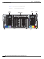
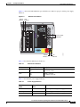
The IPS appliance is a high-performance, plug-and-play device. The appliance is a component of the
IPS, a network-based, real-time intrusion prevention system. You can use the IPS CLI, IDM, IME,
ASDM, or CSM to configure the appliance. For a list of IPS documents and how to access them, refer
to Documentation Roadmap for Cisco Intrusion Prevention System 7.1.
Cisco Intrusion Prevention System Appliance Hardware Installation Guide for IPS 7.1
1-20
OL-24002-01
Chapter 1
Introducing the Sensor
IPS Appliances
You can configure the appliance to respond to recognized signatures as it captures and analyzes network
traffic. These responses include logging the event, forwarding the event to the manager, performing a
TCP reset, generating an IP log, capturing the alert trigger packet, and reconfiguring a router. The
appliance offers significant protection to your network by helping to detect, classify, and stop threats
including worms, spyware and adware, network viruses, and application abuse.
After being installed at key points in the network, the appliance monitors and performs real-time analysis
of network traffic by looking for anomalies and misuse based on an extensive, embedded signature
library. When the system detects unauthorized activity, appliances can terminate the specific connection,
permanently block the attacking host, log the incident, and send an alert to the manager. Other legitimate
connections continue to operate independently without interruption.
Appliances are optimized for specific data rates and are packaged in Ethernet, Fast Ethernet, and Gigabit
Ethernet configurations. In switched environments, appliances must be connected to the SPAN port or
VACL capture port of the switch.
The Cisco IPS appliances provide the following:
•
Protection of multiple network subnets through the use of up to eight interfaces
•
Simultaneous, dual operation in both promiscuous and inline modes
•
A wide array of performance options—from 80 Mbps to multiple gigabits
•
Embedded web-based management solutions packaged with the sensor
For More Information
•
For a list of supported appliances, see Supported Sensors, page 1-18.
•
For a description of the IPS 4240 and IPS 4255, see Chapter 3, “Installing the IPS 4240 and IPS
4255.”
•
For a description of the IPS 4270-20, see Chapter 3, “Installing the IPS 4270-20.”
•
For a description of the IPS 4345 and IPS 4360, see Chapter 4, “Installing the IPS 4345 and
IPS 4360.”
•
For a description of the IPS 4510 and IPS 4520, see Chapter 5, “Installing the IPS 4510 and
IPS 4520.”
•
For a description of the ASA 5500 AIP SSM, see Chapter 6, “Installing and Removing the ASA
5500 AIP SSM.”
•
For a description of the ASA 5585-X IPS SSP, see Chapter 7, “Installing and Removing the
ASA 5585-X IPS SSP.”
Appliance Restrictions
The following restrictions apply to using and operating the appliance:
•
The appliance is not a general purpose workstation.
•
Cisco Systems prohibits using the appliance for anything other than operating Cisco IPS.
•
Cisco Systems prohibits modifying or installing any hardware or software in the appliance that is
not part of the normal operation of the Cisco IPS.
Cisco Intrusion Prevention System Appliance Hardware Installation Guide for IPS 7.1
OL-24002-01
1-21
Chapter 1
Introducing the Sensor
Time Sources and the Sensor
Connecting an Appliance to a Terminal Server
A terminal server is a router with multiple, low speed, asynchronous ports that are connected to other
serial devices. You can use terminal servers to remotely manage network equipment, including
appliances.
To set up a Cisco terminal server with RJ-45 or hydra cable assembly connections, follow these steps:
Step 1
Step 2
Connect to a terminal server using one of the following methods:
•
For terminal servers with RJ-45 connections, connect a rollover cable from the console port on the
appliance to a port on the terminal server.
•
For hydra cable assemblies, connect a straight-through patch cable from the console port on the
appliance to a port on the terminal server.
Configure the line and port on the terminal server. In enable mode, enter the following configuration,
where # is the line number of the port to be configured.
config t
line #
login
transport input all
stopbits 1
flowcontrol hardware
speed 9600
exit
exit
wr mem
Step 3
Be sure to properly close a terminal session to avoid unauthorized access to the appliance. If a terminal
session is not stopped properly, that is, if it does not receive an exit(0) signal from the application that
initiated the session, the terminal session can remain open. When terminal sessions are not stopped
properly, authentication is not performed on the next session that is opened on the serial port.
Caution
Always exit your session and return to a login prompt before terminating the application used to establish
the connection.
Caution
If a connection is dropped or terminated by accident, you should reestablish the connection and exit
normally to prevent unauthorized access to the appliance.
Time Sources and the Sensor
This section explains the importance of having a reliable time source for the sensors and how to correct
the time if there is an error. It contains the following topics:
•
The Sensor and Time Sources, page 1-23
•
Synchronizing IPS Module System Clocks with the Parent Device System Clock, page 1-23
•
Verifying the Sensor is Synchronized with the NTP Server, page 1-23
Cisco Intrusion Prevention System Appliance Hardware Installation Guide for IPS 7.1
1-22
OL-24002-01
Chapter 1
Introducing the Sensor
Time Sources and the Sensor
•
Correcting the Time on the Sensor, page 1-24
The Sensor and Time Sources
Note
We recommend that you use an NTP server to regulate time on your sensor. You can use authenticated
or unauthenticated NTP. For authenticated NTP, you must obtain the NTP server IP address, NTP server
key ID, and the key value from the NTP server. You can set up NTP during initialization or you can
configure NTP through the CLI, IDM, IME, or ASDM.
The sensor requires a reliable time source. All events (alerts) must have the correct UTC and local time
stamp, otherwise, you cannot correctly analyze the logs after an attack. When you initialize the sensor,
you set up the time zones and summertime settings. This section provides a summary of the various ways
to set the time on sensors.
The IPS Standalone Appliances
•
Use the clock set command to set the time. This is the default.
•
Configure the appliance to get its time from an NTP time synchronization source.
Note
The currently supported Cisco IPS appliances are the IPS 4240, IPS 4255, and IPS 4260 [IPS
7.0(x) and later and IPS 7.1(5) and later], IPS 4270-20 [IPS 7.1(3) and later], IPS 4345 and
IPS 4360 [IPS 7.1(3) and later], and IPS 4510 and IPS 4520 [IPS 7.1(4) and later].
The ASA IPS Modules
•
The ASA 5500-X IPS SSP and ASA 5585-X IPS SSP automatically synchronize their clocks with
the clock in the adaptive security appliance in which they are installed. This is the default.
•
Configure them to get their time from an NTP time synchronization source, such as a Cisco router
other than the parent router.
Synchronizing IPS Module System Clocks with the Parent Device System Clock
The ASA IPS modules (ASA 5500 AIP SSM, ASA 5500-X IPS SSP, and ASA 5585-X IPS SSP)
synchronize their clocks to the parent chassis clock (switch, router, or adaptive security appliance) each
time the IPS boots up and any time the parent chassis clock is set. The IPS clock and parent chassis clock
tend to drift apart over time. The difference can be as much as several seconds per day. To avoid this
problem, make sure that both the IPS clock and the parent clock are synchronized to an external NTP
server. If only the IPS clock or only the parent chassis clock is synchronized to an NTP server, the time
drift occurs.
Verifying the Sensor is Synchronized with the NTP Server
In the Cisco IPS, you cannot apply an incorrect NTP configuration, such as an invalid NTP key value or
ID, to the sensor. If you try to apply an incorrect configuration, you receive an error message. To verify
the NTP configuration, use the show statistics host command to gather sensor statistics. The NTP
statistics section provides NTP statistics including feedback on sensor synchronization with the NTP
server.
Cisco Intrusion Prevention System Appliance Hardware Installation Guide for IPS 7.1
OL-24002-01
1-23
Chapter 1
Introducing the Sensor
Time Sources and the Sensor
To verify the NTP configuration, follow these steps:
Step 1
Log in to the sensor.
Step 2
Generate the host statistics.
sensor# show statistics host
...
NTP Statistics
remote
refid
st t when poll reach
11.22.33.44
CHU_AUDIO(1)
8 u
36
64
1
LOCAL(0)
73.78.73.84
5 l
35
64
1
ind assID status conf reach auth condition last_event
1 10372 f014
yes
yes
ok
reject
reachable
2 10373 9014
yes
yes none
reject
reachable
status = Not Synchronized
...
Step 3
offset
0.069
0.000
jitter
0.001
0.001
delay
0.518
0.000
cnt
2
2
offset
37.975
0.000
jitter
33.465
0.001
Generate the hosts statistics again after a few minutes.
sensor# show statistics host
...
NTP Statistics
remote
refid
st t when poll reach
*11.22.33.44
CHU_AUDIO(1)
8 u
22
64 377
LOCAL(0)
73.78.73.84
5 l
22
64 377
ind assID status conf reach auth condition last_event
1 10372 f624
yes
yes
ok
sys.peer
reachable
2 10373 9024
yes
yes none
reject
reachable
status = Synchronized
Step 4
delay
0.536
0.000
cnt
1
1
If the status continues to read Not Synchronized, check with the NTP server administrator to make sure
the NTP server is configured correctly.
Correcting the Time on the Sensor
If you set the time incorrectly, your stored events will have the incorrect time because they are stamped
with the time the event was created. The Event Store time stamp is always based on UTC time. If during
the original sensor setup, you set the time incorrectly by specifying 8:00 p.m. rather than 8:00 a.m.,
when you do correct the error, the corrected time will be set backwards. New events might have times
older than old events.
For example, if during the initial setup, you configure the sensor as central time with daylight saving
time enabled and the local time is 8:04 p.m., the time is displayed as 20:04:37 CDT and has an offset
from UTC of -5 hours (01:04:37 UTC, the next day). A week later at 9:00 a.m., you discover the error:
the clock shows 21:00:23 CDT. You then change the time to 9:00 a.m. and now the clock shows
09:01:33 CDT. Because the offset from UTC has not changed, it requires that the UTC time now be
14:01:33 UTC, which creates the time stamp problem.
To ensure the integrity of the time stamp on the event records, you must clear the event archive of the
older events by using the clear events command.
Note
You cannot remove individual events.
Cisco Intrusion Prevention System Appliance Hardware Installation Guide for IPS 7.1
1-24
OL-24002-01
Chapter 1
Introducing the Sensor
Time Sources and the Sensor
For More Information
For the procedure for clearing events, refer to Clearing Events from Event Store.
Cisco Intrusion Prevention System Appliance Hardware Installation Guide for IPS 7.1
OL-24002-01
1-25
Chapter 1
Introducing the Sensor
Time Sources and the Sensor
Cisco Intrusion Prevention System Appliance Hardware Installation Guide for IPS 7.1
1-26
OL-24002-01
CH APT ER
2
Preparing the Appliance for Installation
This chapter describes the steps to follow before installing new hardware or performing hardware
upgrades, and includes the following sections:
•
Installation Preparation, page 2-1
•
Safety Recommendations, page 2-2
•
General Site Requirements, page 2-5
Installation Preparation
To prepare for installing an appliance, follow these steps:
Step 1
Review the safety precautions outlined in one of the following safety documents:
•
Regulatory Compliance and Safety Information for the Cisco Intrusion Prevention System 4200
Series Appliance Sensor
•
Regulatory Compliance and Safety Information for the Cisco ASA 5500-X Series Adaptive Security
Appliances and the Intrusion Prevention System 4300 Series Appliances
•
Regulatory Compliance and Safety Information for the Cisco Intrusion Prevention System 4500
Series Sensor Appliance
Step 2
To familiarize yourself with the IPS and related documentation and where to find it on Cisco.com, read
the Documentation Roadmap for Cisco Intrusion Prevention System 7.1.
Step 3
Before proceeding with appliance installation, read the Release Notes for your software version, found
at this URL:
http://www.cisco.com/en/US/products/hw/vpndevc/ps4077/prod_release_notes_list.html
Step 4
Unpack the appliance. An accessory kit ships with the appliance. Refer to the chapter for your appliance
for the accessory kit contents.
Step 5
Place the appliance in an ESD-controlled environment.
Step 6
Place the appliance on a stable work surface.
Step 7
For installation instructions, see the chapter on your sensor in this book, Cisco Intrusion Prevention
System Appliance and Module Installation Guide for IPS 7.1.
Cisco Intrusion Prevention System Appliance Hardware Installation Guide for IPS 7.1
OL-24002-01
2-1
Chapter 2
Preparing the Appliance for Installation
Safety Recommendations
For More Information
•
For ESD guidelines, see Electricity Safety Guidelines, page 2-2.
•
For the procedure for working in an ESD environment, see Working in an ESD Environment,
page 2-4.
Safety Recommendations
This section lists the safety precautions you should take when working with IPS appliances, and contains
the following topics:
•
Safety Guidelines, page 2-2
•
Electricity Safety Guidelines, page 2-2
•
Preventing Electrostatic Discharge Damage, page 2-3
•
Working in an ESD Environment, page 2-4
Safety Guidelines
Use the following guidelines to help ensure your safety and protect the appliance. The list of guidelines
may not address all potentially hazardous situations in your working environment, so be alert and
exercise good judgment at all times.
Note
Removing the chassis cover to install a hardware component does not affect your Cisco warranty.
Upgrading the appliance does not require any special tools and does not create any radio frequency leaks.
The safety guidelines are as follows:
•
Keep the chassis area clear and dust-free before, during and after installation.
•
Keep tools away from walk areas where you and others could fall over them.
•
Do not wear loose clothing or jewelry, such as earrings, bracelets, or chains, that could get caught
in the chassis.
•
Wear safety glasses if you are working under any conditions that might be hazardous to your eyes.
•
Do not perform any action that creates a potential hazard to people or makes the equipment unsafe.
•
Never attempt to lift an object that is too heavy for one person to handle.
Electricity Safety Guidelines
Warning
Before working on a chassis or working near power supplies, unplug the power cord on AC units;
disconnect the power at the circuit breaker on DC units. Statement 12
Cisco Intrusion Prevention System Appliance Hardware Installation Guide for IPS 7.1
2-2
OL-24002-01
Chapter 2
Preparing the Appliance for Installation
Safety Recommendations
Follow these guidelines when working on equipment powered by electricity:
•
Before beginning procedures that require access to the interior of the chassis, locate the emergency
power-off switch for the room in which you are working. Then, if an electrical accident occurs, you
can act quickly to turn off the power.
•
Do not work alone if potentially hazardous conditions exist anywhere in your work space.
•
Never assume that power is disconnected from a circuit; always check the circuit.
•
Look carefully for possible hazards in your work area, such as moist floors, ungrounded power
extension cables, frayed power cords, and missing safety grounds.
•
If an electrical accident occurs, proceed as follows:
– Use caution; do not become a victim yourself.
– Disconnect power from the system.
– If possible, send another person to get medical aid. Otherwise, assess the condition of the victim
and then call for help.
– Determine if the person needs rescue breathing or external cardiac compressions; then take
appropriate action.
•
Use the chassis within its marked electrical ratings and product usage instructions.
•
Install the appliance in compliance with local and national electrical codes as listed in one of the
following safety documents:
– Regulatory Compliance and Safety Information for the Cisco Intrusion Prevention System 4200
Series Appliance Sensor
– Regulatory Compliance and Safety Information for the Cisco ASA 5500-X Series Adaptive
Security Appliances and the Intrusion Prevention System 4300 Series Appliances
– Regulatory Compliance and Safety Information for the Cisco Intrusion Prevention System 4500
Series Sensor Appliance
•
The sensor models equipped with AC-input power supplies are shipped with a 3-wire electrical cord
with a grounding-type plug that fits only a grounding-type power outlet. This is a safety feature that
you should not circumvent. Equipment grounding should comply with local and national electrical
codes.
Preventing Electrostatic Discharge Damage
Electrostatic discharge (ESD) can damage equipment and impair electrical circuitry. ESD damage occurs
when electronic components are improperly handled, which can result in complete or intermittent
failures.
•
Always follow ESD-prevention procedures when you remove and replace components. Make sure
that the chassis is electrically connected to earth ground. Wear an ESD-preventive wrist strap, and
make sure that it makes good skin contact. Connect the grounding clip to an unpainted surface of
the chassis frame to safely ground unwanted ESD voltage. To guard against ESD damage and
shocks, the wrist strap and cord must operate properly. If no wrist strap is available, ground yourself
by touching the metal part of the chassis.
•
For safety, periodically check the resistance value of the anti-static strap, which should be between
1 and 10 megohms (Mohms).
Cisco Intrusion Prevention System Appliance Hardware Installation Guide for IPS 7.1
OL-24002-01
2-3
Chapter 2
Preparing the Appliance for Installation
Safety Recommendations
Working in an ESD Environment
Work on ESD-sensitive parts only at an approved static-safe station on a grounded static dissipative work
surface, for example, an ESD workbench or static dissipative mat.
To remove and replace components in a sensor, follow these steps:
Step 1
Remove all static-generating items from your work area.
Step 2
Use a static dissipative work surface and wrist strap.
Note
Step 3
Disposable wrist straps, typically those included with an upgrade part, are designed for one time
use.
Attach the wrist strap to your wrist and to the terminal on the work surface. If you are using a disposable
wrist strap, connect the wrist strap directly to an unpainted metal surface of the chassis.
100 Mbps Link
PIX-515
DO NOT INSTALL INTERFACE
CARDS WITH POWER APPLIED
FDX
10/100 ETHERNET 0/0
Step 4
Caution
100 Mbps Link
FAILOVER
FDX
10/100 ETHERNET 0/0
148409
Copper foil
CONSOLE
Connect the work surface to the chassis using a grounding cable and alligator clip.
Always follow ESD-prevention procedures when removing, replacing, or repairing components.
Note
If you are upgrading a component, do not remove the component from the ESD packaging until
you are ready to install it.
Cisco Intrusion Prevention System Appliance Hardware Installation Guide for IPS 7.1
2-4
OL-24002-01
Chapter 2
Preparing the Appliance for Installation
General Site Requirements
General Site Requirements
This section describes the requirements your site must meet for safe installation and operation of your
IPS appliance. This section includes the following topics:
•
Site Environment, page 2-5
•
Preventive Site Configuration, page 2-5
•
Power Supply Considerations, page 2-6
•
Configuring Equipment Racks, page 2-6
Site Environment
Place the appliance on a desktop or mount it in a rack. The location of the appliance and the layout of
the equipment rack or wiring room are extremely important for proper system operation. Equipment
placed too close together, inadequate ventilation, and inaccessible panels can cause system malfunctions
and shutdowns, and can make appliance maintenance difficult.
When planning the site layout and equipment locations, keep in mind the following precautions to help
avoid equipment failures and reduce the possibility of environmentally-caused shutdowns. If you are
experiencing shutdowns or unusually high errors with your existing equipment, these precautions may
help you isolate the cause of failures and prevent future problems.
•
Electrical equipment generates heat. Ambient air temperature might not be adequate to cool
equipment to acceptable operating temperatures without adequate circulation. Make sure that the
room in which you operate your system has adequate air circulation.
•
Always follow the ESD-prevention procedures to avoid damage to equipment. Damage from static
discharge can cause immediate or intermittent equipment failure.
•
Make sure that the chassis top panel is secure. The chassis is designed to allow cooling air to flow
effectively within it. An open chassis allows air leaks, which can interrupt and redirect the flow of
cooling air from the internal components.
Preventive Site Configuration
The following precautions will help plan an acceptable operating environment for the chassis and avoid
environmentally caused equipment failures:
•
Electrical equipment generates heat. Ambient air temperature might not be adequate to cool
equipment to acceptable operating temperatures without adequate circulation. Ensure that the room
in which you operate your system has adequate air circulation.
•
Always follow the ESD-prevention procedures described previously to avoid damage to equipment.
Damage from static discharge can cause immediate or intermittent equipment failure.
•
Ensure that the chassis top panel is secure. The chassis is designed to allow cooling air to flow
effectively within it. An open chassis allows air leaks, which may interrupt and redirect the flow of
cooling air from the internal components.
Cisco Intrusion Prevention System Appliance Hardware Installation Guide for IPS 7.1
OL-24002-01
2-5
Chapter 2
Preparing the Appliance for Installation
General Site Requirements
Power Supply Considerations
The IPS 4270-20 has an AC power supply. The IPS 4345, IPS 4360, IPS 4510, and IPS 4520 have either
an AC or DC power supply.
Follow these guidelines for power supplies:
•
Check the power at the site before installing the chassis to ensure that the power is free of spikes
and noise. Install a power conditioner if necessary, to ensure proper voltages and power levels in the
source voltage.
•
Install proper grounding for the site to avoid damage from lightning and power surges.
•
The following applies to a chassis equipped with an AC-input power supply:
– The chassis does not have a user-selectable operating range. Refer to the label on the chassis for
the correct AC-input power requirement.
– Several types of AC-input power supply cords are available; make sure you have the correct type
for your site.
– Install a UPS for your site.
– Install proper site-grounding facilities to guard against damage from lightning or power surges.
Configuring Equipment Racks
The following tips help you plan an acceptable equipment rack configuration:
•
Enclosed racks must have adequate ventilation. Ensure that the rack is not overly congested, because
each chassis generates heat. An enclosed rack should have louvered sides and a fan to provide
cooling air.
•
When mounting a chassis in an open rack, ensure that the rack frame does not block the intake or
exhaust ports. If the chassis is installed on slides, check the position of the chassis when it is seated
all the way into the rack.
•
In an enclosed rack with a ventilation fan in the top, excessive heat generated by equipment near the
bottom of the rack can be drawn upward and into the intake ports of the equipment above it in the
rack. Ensure that you provide adequate ventilation for equipment at the bottom of the rack.
•
Baffles can help to isolate exhaust air from intake air, which also helps to draw cooling air through
the chassis. The best placement of the baffles depends on the airflow patterns in the rack.
Experiment with different arrangements to position the baffles effectively.
Cisco Intrusion Prevention System Appliance Hardware Installation Guide for IPS 7.1
2-6
OL-24002-01
CH APT ER
3
Installing the IPS 4270-20
Contents
This chapter describes the IPS 4270-20, and includes the following sections:
•
Installation Notes and Caveats, page 3-1
•
Product Overview, page 3-2
•
Supported Interface Cards, page 3-4
•
Hardware Bypass, page 3-5
•
Front and Back Panel Features, page 3-8
•
Diagnostic Panel, page 3-14
•
Specifications, page 3-15
•
Accessories, page 3-16
•
Installing the Rail System Kit, page 3-16
•
Installing the IPS 4270-20, page 3-35
•
Removing and Replacing the Chassis Cover, page 3-39
•
Accessing the Diagnostic Panel, page 3-42
•
Installing and Removing Interface Cards, page 3-43
•
Installing and Removing the Power Supply, page 3-45
•
Installing and Removing Fans, page 3-50
•
Troubleshooting Loose Connections, page 3-52
Installation Notes and Caveats
Pay attention to the following installation notes and caveats before installing the IPS 4270-20.
Caution
The BIOS on the IPS 4270-20 is specific to the IPS 4270-20 and must only be upgraded under
instructions from Cisco with BIOS files obtained from the Cisco website. Installing a non-Cisco or
third-party BIOS on the IPS 4270-20 voids the warranty. For more information on how to obtain
instructions and BIOS files from the Cisco website, see Obtaining Cisco IPS Software, page C-1.
Cisco Intrusion Prevention System Appliance Hardware Installation Guide for IPS 7.1
OL-24002-01
3-1
Chapter 3
Installing the IPS 4270-20
Product Overview
Warning
This product relies on the building’s installation for short-circuit (overcurrent) protection. Ensure that
the protective device is rated not greater than 120 VAC, 20 A U.S. (240 VAC, 16-20 A International).
Statement 1005
Warning
This equipment must be grounded. Never defeat the ground conductor or operate the equipment in the
absence of a suitably installed ground conductor. Contact the appropriate electrical inspection
authority or an electrician if you are uncertain that suitable grounding is available. Statement 1024
Warning
Blank faceplates and cover panels serve three important functions: they prevent exposure to
hazardous voltages and currents inside the chassis; they contain electromagnetic interference (EMI)
that might disrupt other equipment; and they direct the flow of cooling air through the chassis. Do not
operate the system unless all cards, faceplates, front covers, and rear covers are in place. Statement
1029
Warning
This unit might have more than one power supply connection. All connections must be removed to
de-energize the unit. Statement 1028
Note
Removing the appliance chassis cover does not affect your Cisco warranty. Upgrading the IPS 4270-20
does not require any special tools and does not create any radio frequency leaks.
Note
In IPS 7.1, rx/tx flow control is disabled on the IPS 4270-20. This is a change from IPS 7.0 where rx/tx
flow control is enabled by default.
Caution
Do not operate the IPS 4270-20 for long periods with the chassis cover open or removed. Operating it in
this manner results in improper airflow and improper cooling that can lead to thermal damage.
Note
On IPS sensors with multiple processors (for example, the IPS 4260 and IPS 4270-20), packets may be
captured out of order in the IP logs and by the packet command. Because the packets are not processed
using a single processor, the packets can become out of sync when received from multiple processors.
Product Overview
The IPS 4270-20 delivers up to 4 Gbps of performance in media-rich environments and 2 Gbps in
transactional environments enabling you to protect fully saturated Gigabit networks and aggregate
network traffic on multiple sensing interfaces. The IPS 4270-20 is also inline ready and has support for
both copper and fiber NICs thus providing flexibility of deployment in any environment.
Cisco Intrusion Prevention System Appliance Hardware Installation Guide for IPS 7.1
3-2
OL-24002-01
Chapter 3
Installing the IPS 4270-20
Product Overview
Media-rich environments are characterized by content, such as that seen on popular websites with video
and file transfer. Transactional environments are characterized by connections, such as E-commerce,
instant messaging, and voice. Figure 3-1 demonstrates the spectrum of media-rich and transactional
environments.
Figure 3-1
Media-rich and Transactional Environments
Gaming
Commerce
Voice
Collaborative
Workspaces
WWW
Data
Replication
Web 2.0
MEDIA-RICH
250389
TRANSACTIONAL
Instant
Messaging
Streaming
Video
The IPS 4270-20 has two built-in GigabitEthernet network ports and nine expansion slots. The network
port numbers are numbered from top to bottom beginning with 0 and the expansion slot numbers increase
from right to left. The two built-in GigabitEthernet ports are used for management and are called
Management0/0 and Management0/1. Management0/1 is reserved for future use. Slots 1 and 2 are
reserved for future use. You can populate slots 3 through 8 with supported network interface cards. Slot
9 is populated by a RAID controller card and is not available for use by network interface cards. The
sensing interfaces are called GigabitEthernet.
Because of the multiple interfaces on the IPS 4270-20, it can cover multiple subnets, each of which have
bandwidth requirements in the multi-T3 range or Gigabit range, and the multiple interfaces can be
connected directly to the additional monitoring interfaces without needing to SPAN the traffic through
a switch.
For improved reliability, the IPS 4270-20 uses a compact flash device for storage rather than a hard-disk
drive. The IPS 4270-20 supports two optional network interface cards, the 2SX interface card with
fiber-optic ports, and the 4GE bypass interface card with copper ports that contains the hardware-bypass
feature. Initially the IPS 4270-20 supports only the built-in interfaces and these two interface cards.
The IPS 4270-20 supports a maximum of 16 sensing ports. Any additional configured ports will not be
monitored and will not appear in the IPS configuration or statistics and no inline traffic will be forwarded
on or between these ports. You receive the following error if you exceed the number of supported ports:
The number of installed network interfaces exceeds the limit of 16. The excess interfaces
are ignored.
Note
If you add a new interface card that exceeds the limit, one or more of the previous sensing interfaces may
become disabled.
The IPS 4270-20 ships with two power supplies, thus supporting a redundant power supply
configuration. The IPS 4270-20 operates in load-sharing mode when the redundant power supply is
installed.
For More Information
•
For more information on sensor interfaces, see Sensor Interfaces, page 1-4.
•
For more information on the supported interface cards, see Supported Interface Cards, page 3-4.
Cisco Intrusion Prevention System Appliance Hardware Installation Guide for IPS 7.1
OL-24002-01
3-3
Chapter 3
Installing the IPS 4270-20
Supported Interface Cards
•
For more information on the 4GE bypass interface card, see Hardware Bypass, page 3-5.
•
For more information about the power supplies, see Installing and Removing the Power Supply,
page 3-45.
Supported Interface Cards
The IPS 4270-20 supports three interface cards: the 4GE bypass interface card, the 2SX interface card,
and the 10GE interface card.
4GE Bypass Interface Card
The 4GE bypass interface card (part numbers IPS-4GE-BP-INT and IPS-4GE-BP-INT=) provides four
10/100/1000BASE-T (4GE) monitoring interfaces. The IPS 4270-20 supports up to four 4GE bypass
interface cards for a total of sixteen GE bypass interfaces. The 4GE bypass interface card supports
hardware bypass.
Figure 3-2 shows the 4GE bypass interface card.
4GE Bypass Interface Card
153325
Figure 3-2
2SX Interface Card
The 2SX interface card (part numbers IPS-2SX-INT and IPS-2SX-INT=) provides two 1000BASE-SX
(fiber) monitoring interfaces. The IPS 4270-20 supports up to six 2SX interface cards for a total of
twelve SX interfaces.
The 2SX card ports require a multi-mode fiber cable with an LC connector to connect to the SX interface
of the sensor. The 2SX interface card does not support hardware bypass.
Cisco Intrusion Prevention System Appliance Hardware Installation Guide for IPS 7.1
3-4
OL-24002-01
Chapter 3
Installing the IPS 4270-20
Hardware Bypass
Figure 3-3 shows the 2SX interface card.
2SX Interface Card
190474
Figure 3-3
10GE Interface Card
The 10GE interface card (part numbers IPS-2X10GE-SR-INT and IPS-2X10GE-SR-INT=) provides two
10000 Base-SX (fiber) interfaces. The IPS 4270-20 supports up to two 10GE interface cards for a total
of four 10GE fiber interfaces.
The card ports require a multi-mode fiber cable with an LC connector to connect to the SX interface of
the IPS 4270-20. The 10GE interface card does not support hardware bypass.
Figure 3-4 shows the 10GE interface card.
10GE Interface Card
253975
Figure 3-4
GigabitEthernet slot_number/port_number is the expansion card interface naming convention for the
IPS 4270-20. The slot number is shown above the slot in the chassis and the port number is numbered
from top to bottom starting with 0.
Hardware Bypass
This section describes the 4GE bypass interface card and its configuration restrictions. For the procedure
for installing and removing the 4GE bypass interface card, see Installing and Removing Interface Cards,
page 3-43. This section contains the following topics:
•
4GE Bypass Interface Card, page 3-6
•
Hardware Bypass Configuration Restrictions, page 3-6
•
Hardware Bypass and Link Changes and Drops, page 3-7
Cisco Intrusion Prevention System Appliance Hardware Installation Guide for IPS 7.1
OL-24002-01
3-5
Chapter 3
Installing the IPS 4270-20
Hardware Bypass
4GE Bypass Interface Card
The IPS 4270-20 supports the 4-port GigabitEthernet card (part number IPS-4GE-BP-INT=) with
hardware bypass. This 4GE bypass interface card supports hardware bypass only between ports 0 and 1
and between ports 2 and 3.
Note
To disable hardware bypass, pair the interfaces in any other combination, for example 2/0<->2/2 and
2/1<->2/3.
Hardware bypass complements the existing software bypass feature in Cisco IPS. The following
conditions apply to hardware bypass and software bypass:
•
When bypass is set to OFF, software bypass is not active.
For each inline interface for which hardware bypass is available, the component interfaces are set to
disable the fail-open capability. If SensorApp fails, the sensor is powered off, reset, or if the NIC
interface drivers fail or are unloaded, the paired interfaces enter the fail-closed state (no traffic flows
through inline interface or inline VLAN subinterfaces).
•
When bypass is set to ON, software bypass is active.
Software bypass forwards packets between the paired physical interfaces in each inline interface and
between the paired VLANs in each inline VLAN subinterface. For each inline interface on which
hardware bypass is available, the component interfaces are set to standby mode. If the sensor is
powered off, reset, or if the NIC interfaces fail or are unloaded, those paired interfaces enter
fail-open state in hardware (traffic flows unimpeded through inline interface). Any other inline
interfaces enter fail-closed state.
•
When bypass is set to AUTO (traffic flows without inspection), software bypass is activated if
SensorApp fails.
For each inline interface on which hardware bypass is available, the component interfaces are set to
standby mode. If the sensor is powered off, reset, or if the NIC interfaces fail or are unloaded, those
paired interfaces enter fail-open state in hardware. Any other inline interfaces enter the fail-closed
state.
Note
To test fail-over, set the bypass mode to ON or AUTO, create one or more inline interfaces
and power down the sensor and verify that traffic still flows through the inline path.
Hardware Bypass Configuration Restrictions
To use the hardware bypass feature on the 4GE bypass interface card, you must pair interfaces to support
the hardware design of the card. If you create an inline interface that pairs a hardware-bypass-capable
interface with an interface that violates one or more of the hardware-bypass configuration restrictions,
hardware bypass is deactivated on the inline interface and you receive a warning message similar to the
following:
Hardware bypass functionality is not available on Inline-interface pair0.
Physical-interface GigabitEthernet2/0 is capable of performing hardware bypass only when
paired with GigabitEthernet2/1, and both interfaces are enabled and configured with the
same speed and duplex settings.
Cisco Intrusion Prevention System Appliance Hardware Installation Guide for IPS 7.1
3-6
OL-24002-01
Chapter 3
Installing the IPS 4270-20
Hardware Bypass
The following configuration restrictions apply to hardware bypass:
•
The 4-port bypass card is only supported on the IPS 4270-20.
•
Fail-open hardware bypass only works on inline interfaces (interface pairs), not on inline VLAN
pairs.
•
Fail-open hardware bypass is available on an inline interface if all of the following conditions are
met:
– Both of the physical interfaces support hardware bypass.
– Both of the physical interfaces are on the same interface card.
– The two physical interfaces are associated in hardware as a bypass pair.
– The speed and duplex settings are identical on the physical interfaces.
– Both of the interfaces are administratively enabled.
•
Autonegotiation must be set on MDI/X switch ports connected to the IPS 4270-20.
You must configure both the sensor ports and the switch ports for autonegotiation for hardware
bypass to work. The switch ports must support MDI/X, which automatically reverses the transmit
and receive lines if necessary to correct any cabling problems. The sensor is only guaranteed to
operate correctly with the switch if both of them are configured for identical speed and duplex,
which means that the sensor must be set for autonegotiation too.
Hardware Bypass Turned Off for System Image Recovery or Reimage
Hardware bypass starts when you enter the recover application command and the interfaces are paired
correctly. Hardware bypass works until the IPS starts up again with the empty configuration. Because all
interfaces default to disabled and are no longer paired, when the SensorApp loads, it stops hardware
bypass and sets the interfaces to link down. BEFORE you perform a reimage or recover, make sure you
bypass the traffic at the switch.
Hardware Bypass and Link Changes and Drops
Properly configuring and deploying hardware bypass protects against complete link failure if the IPS
appliance experiences a power loss, critical hardware failure, or is rebooted; however, a link status
change still occurs when hardware bypass engages (and again when it disengages).
During engagement, the interface card disconnects both physical connections from itself and bridges
them together. The interfaces of the connected devices can then negotiate the link and traffic forwarding
can resume. Once the appliance is back online, hardware bypass disengages and the interface card
interrupts the bypass and reconnects the links back to itself. The interface card then negotiates both links
and traffic resumes.
There is no built-in way to completely avoid link status changes and drops. However, you can greatly
reduce the interruption time (in some cases to sub-second times) by doing the following:
•
Make sure you use CAT 5e/6-certified cabling for all connections.
•
Make sure the interfaces of the connected devices are configured to match the interfaces of the
appliance for speed/duplex negotiation (auto/auto).
•
Enable portfast on connected switchports to reduce spanning-tree forwarding delays.
Cisco Intrusion Prevention System Appliance Hardware Installation Guide for IPS 7.1
OL-24002-01
3-7
Chapter 3
Installing the IPS 4270-20
Front and Back Panel Features
Front and Back Panel Features
This section describes the IPS 4270-20 front and back panel features, indicators, and internal
components. Figure 3-5 shows the front view of the IPS 4270-20.
Figure 3-5
IPS 4270-20 Front View
Switches/Indicators
1
2
3
4
5
6
7
8
Cisco IPS 4270 SERIES
Intrusion Prevention Sensor
250082
US
AT
EM ST T 0 T 1
ST R M M
UID SY PW MG MG
Figure 3-6 shows the front panel switches and indicators.
Figure 3-6
IPS 4270-20 Front Panel Switches and Indicators
Power
status
System
UID
Management0/0
Management0/1
(reserved for
future use)
Power
Cisco IPS 4270 SERIES
Intrusion Prevention Sensor
250108
US
AT
EM ST T 0 T 1
ST R M M
D
UI SY PW MG MG
Cisco Intrusion Prevention System Appliance Hardware Installation Guide for IPS 7.1
3-8
OL-24002-01
Chapter 3
Installing the IPS 4270-20
Front and Back Panel Features
Table 3-1 describes the front panel switches and indicators on the IPS 4270-20.
Table 3-1
Front Panel Switches and Indicators
Indicator
Description
UID switch and
indicator
Toggles the system ID indicator, which assists with chassis location in a rack:
•
Blue—Activated
•
Off—Deactivated
Note
Internal system
health indicator
Power status
indicator
MGMT0/0 indicator
The ID switch is activated by a switch on the front of the chassis.
Indicates internal system health:
•
Green—System on
•
Flashing amber—System health degraded
•
Flashing red—System health critical
•
Off—System off
Indicates the power supply status:
•
Green—Power supply on
•
Flashing amber—Power supply health degraded
•
Flashing red—Power supply health critical
•
Off—Power supply off
Indicates the status of the management port:
•
Green—Linked to network
•
Flashing green—Linked with activity on the network
•
Off—No network connection
MGMT0/1 indicator
Reserved for future use
Power switch and
indicator
Turns power on and off:
•
Amber—System has AC power and is in standby mode
•
Green—System has AC power and is turned on
•
Off—System has no AC power
Cisco Intrusion Prevention System Appliance Hardware Installation Guide for IPS 7.1
OL-24002-01
3-9
Chapter 3
Installing the IPS 4270-20
Front and Back Panel Features
Figure 3-7 shows the back view of the IPS 4270-20.
IPS 4270-20 Back Panel Features
Power
supply 2
PS2
Power
supply 1
Sensing interface
expansion slots
PCI-E x4
9
PCI-E x8
8
7
PCI-E x4 PCI-E x8
6
5
PCI-E x4
4
3
PS1
PCI-X 100 MHz
1
2
CONSOLE
UID
UID
Reserved
T-15 Torx
screwdriver
Reserved
Console
port
Reserved
for
Future Use
1
MGMT0/0
250083
Figure 3-7
Management0/0
Cisco Intrusion Prevention System Appliance Hardware Installation Guide for IPS 7.1
3-10
OL-24002-01
Chapter 3
Installing the IPS 4270-20
Front and Back Panel Features
Figure 3-8 shows the built-in Ethernet port, which has two indicators per port, and the power supply
indicators.
Figure 3-8
Ethernet Port Indicators
Activity Link
indicator indicator
PCI-E x4
4
3
PS1
PCI-X 100 MHz
1
2
Power supply
indicators
Reserved
for
Future Use
CONSOLE
Activity
indicator
Link
indicator
250085
MGMT 0/0
Table 3-2 describes the Ethernet port indicators.
Table 3-2
Ethernet Port Indicators
Indicator
Indicator (Green)
Description
Activity
On or flashing
Off
Network activity
No network activity
Link
On
Off
Linked to network
Not linked to network
Table 3-3 describes the power supply indicators.
Table 3-3
Power Supply Indicators
Fail Indicator 1
Amber
Power Indicator 2
Green
Description
Off
Off
No AC power to any power supply
Flashing
Off
Power supply failure (over current)
On
Off
No AC power to this power supply
Cisco Intrusion Prevention System Appliance Hardware Installation Guide for IPS 7.1
OL-24002-01
3-11
Chapter 3
Installing the IPS 4270-20
Front and Back Panel Features
Table 3-3
Power Supply Indicators (continued)
Fail Indicator 1
Amber
Power Indicator 2
Green
Off
Flashing
Off
On
Description
•
AC power present
•
Standby mode
Normal
Cisco Intrusion Prevention System Appliance Hardware Installation Guide for IPS 7.1
3-12
OL-24002-01
Chapter 3
Installing the IPS 4270-20
Front and Back Panel Features
Figure 3-9 shows the internal components.
Figure 3-9
IPS 4270-20 Internal Components
Power
supply
Sensing interface
expansion slots
Cooling
fans
Power
supply
Cooling
fans
250249
Diagnostic
panel
Cooling
fans
Cisco Intrusion Prevention System Appliance Hardware Installation Guide for IPS 7.1
OL-24002-01
3-13
Chapter 3
Installing the IPS 4270-20
Diagnostic Panel
Diagnostic Panel
The front panel health indicators only indicate the current hardware status. The Diagnostic Panel
indicators identify components experiencing an error, event, or failure. All indicators are off unless one
of the component fails.
Note
When you remove the chassis cover to view the Diagnostic Panel, leave the IPS 4270-20 powered on.
Powering off the IPS 4270-20 clears the Diagnostic Panel indicators.
Figure 3-10 shows the Diagnostic Panel.
INTERLOCK
ERROR
NMI
I/O BD
CPU BD
5C
4B
3B
2A
1A
20B
19B
18A
17A
!
PPM1
6C
PROC1
!
21C
PROC2
MEMORY
7D
FAN5
22C
FAN3
8D
FAN6
23D
16D
15D
14C
13C
12B
11B
10A
9A
PPM2
MEMORY
FAN4
24D
PS2
PS1
POWER
FAULT
Diagnostic Panel
CPU BD
Figure 3-10
FAN1
!
PROC3
!
250250
PROC4
PPM3
32D
31D
30C
29C
28B
27B
26A
25A
PPM4
FAN2
Table 3-4 lists the indicators that display health status for each component:
Table 3-4
Diagnostic Panel Indicators
Indicator
Component
PS1
Power supply (primary)
PS2
Power supply (optional)
CPU BD (power fault)
Processor memory module board
I/O BD
System board
NMI
System NMI switch
Slot X
Expansion slot
CPU BD (interlock error) System board
PPM X
Processor power module
1A-32D
DIMM Slot
PROC X
Processor
FAN X
Fan
Cisco Intrusion Prevention System Appliance Hardware Installation Guide for IPS 7.1
3-14
OL-24002-01
Chapter 3
Installing the IPS 4270-20
Specifications
For More Information
•
For the location of the Diagnostic Panel in the IPS 4270-20 chassis, see Figure 3-9 on page 3-13.
•
For information on how to access the Diagnostic Panel, see Accessing the Diagnostic Panel,
page 3-42.
Specifications
Table 3-5 lists the specifications for the IPS 4270-20.
Table 3-5
IPS 4270-20 Specifications
Dimensions and Weight
Height
6.94 in. (17.6 cm)
Width
19.0 in. (46.3 cm)
Depth
26.5 in. (67.3 cm)
Weight
80 lb (36.3 kg)
Form factor
4 RU, standard 19-inch rack-mountable
Power
Rated input voltage
100 to 127 VAC
200 to 240 VAC
Rated input frequency
50 to 60 Hz
Rated input power
1161W @ 100 VAC
1598W @ 200 VAC
Rated input current
12A (100 VAC)
8A (200 VAC)
Maximum heat dissipation
3960 BTU/hr (100 VAC)
5450 BTU/hr (200 VAC)
Power supply output
910 W (low line)
1300 W (high line)
Environment
Temperature
Operating 50 to 95°F (10 to 35°C)1
Nonoperating -40°F to 158°F (-40°C to 70°C)
Maximum wet bulb temperature
82.4°F (28°C)
Relative humidity
(noncondensing)
Operating 10% to 90%
Nonoperating 5% to 95%
Altitude
Operating 0 to 10,000 ft (3050 m)
Nonoperating 0 to 30,000 ft (9144 m)
Shock
Operating Half-sine 2 G, 11 ms pulse, 100 pulses
Nonoperating 25 G, 170 inches/sec delta V
Vibration
2.2 Grms, 10 minutes per axis on all three axes
1. At sea level with an altitude derating of 1.8°F per every 1000 ft (1.0°C per every 3.0m) above sea level to a maximum of
10,000 ft (3050 m). no direct sustained sunlight.
Cisco Intrusion Prevention System Appliance Hardware Installation Guide for IPS 7.1
OL-24002-01
3-15
Chapter 3
Installing the IPS 4270-20
Accessories
Accessories
The IPS 4270-20 accessories kit contains the following:
•
DB-9 connector
•
DB-9/RJ-45 console cable
•
Two Ethernet RJ-45 cables
•
Regulatory Compliance and Safety Information for the Cisco Intrusion Detection and Prevention
System 4200 Series Appliance Sensor
•
Documentation Roadmap for Cisco Intrusion Prevention System
Installing the Rail System Kit
You can install the IPS 4270-20 in a 4-post rack. This section describes how to install the IPS 4270-20
in a rack, and contains the following sections:
•
Understanding the Rail System Kit, page 3-16
•
Rail System Kit Contents, page 3-17
•
Space and Airflow Requirements, page 3-17
•
Installing the IPS 4270-20 in the Rack, page 3-18
•
Extending the IPS 4270-20 from the Rack, page 3-26
•
Installing the Cable Management Arm, page 3-28
•
Converting the Cable Management Arm, page 3-32
Understanding the Rail System Kit
This rail system supports a variety of products that can be installed in round-, square, or threaded-hole
racks. The following illustration shows the three rack hole-types. Use Figure 3-11 to identify your rack
type and then follow the installation steps accordingly.
Round-, Square-, and Threaded-Hole Racks
Round-hole racks
Square-hole racks
Threaded-hole racks
No tools required
No tools required
Tools required:
standard screwdriver,
Phillips screwdriver,
or T-25 Torx driver
250205
Figure 3-11
Cisco Intrusion Prevention System Appliance Hardware Installation Guide for IPS 7.1
3-16
OL-24002-01
Chapter 3
Installing the IPS 4270-20
Installing the Rail System Kit
No tools are required for the round- and square-hole racks. You may need screws that fit the
threaded-hole rack and a driver for those screws.You need a standard screwdriver to remove the roundand square-hole studs from the slide assemblies when you install the security appliance in a
threaded-whole rack.
This rail system supports a minimum rack depth of 24 in. (60.96 cm) and a maximum rack depth of 36.5
in. (92.71 cm).
Rail System Kit Contents
The rail system kit contains the following items:
•
Two slide assemblies
•
Two chassis rails
•
Four Velcro straps
•
Six zip ties
•
One cable management arm
•
A package of miscellaneous parts (screws, and so forth)
•
One cable management arm stop bracket
Space and Airflow Requirements
To allow for servicing and adequate airflow, follow these space and airflow requirements when choosing
where to place a rack:
•
Leave a minimum clearance of 25 in. (63.5 cm) in front of the rack.
•
Leave a minimum clearance of 30 in. (76.2 cm) behind the rack.
•
Leave a minimum clearance of 48 in. (121.9 cm) from the back of the rack to the back of another
rack or row of racks.
IPS 4270-20 draws in cool air through the front and expels warm air through the back. The front and
back rack doors must be adequately ventilated to allow ambient room air to enter the chassis and the back
must be adequately ventilated to allow warm air to escape from the chassis.
Cisco Intrusion Prevention System Appliance Hardware Installation Guide for IPS 7.1
OL-24002-01
3-17
Chapter 3
Installing the IPS 4270-20
Installing the Rail System Kit
Installing the IPS 4270-20 in the Rack
To prevent bodily injury when mounting or servicing this unit in a rack, you must take special
precautions to ensure that the system remains stable. The following guidelines are provided to
ensure your safety:
Warning
•
This unit should be mounted at the bottom of the rack if it is the only unit in the rack.
•
When mounting this unit in a partially filled rack, load the rack from the bottom to the top with the heaviest
component at the bottom of the rack.
•
If the rack is provided with stabilizing devices, install the stabilizers before mounting or servicing the unit in
the rack. Statement 1006
This procedure requires two or more people to position the IPS 4270-20 on the slide assemblies before
pushing it in to the rack.
Warning
To install the IPS 4270-20 in the rack, follow these steps:
Attach the chassis side rail to the IPS 4270-20 by aligning the chassis rail to the stud on the IPS 4270-20,
pressing the chassis side rail in to the stud, and then sliding the chassis side rail backwards until you hear
the latch catch.
Step 1
1
2
3
4
5
6
7
8
Cisco IPS
4270
Intrusion SERIES
Preventio
n Sensor
250206
US
EM STAT 0 1
UID SYST R MT MT
PW MG MG
Note
Step 2
The tapered end of the chassis side rail should be at the back of the IPS 4270-20. The chassis
side rail is held in place by the inner latch.
Repeat Step 1 for each chassis side rail.
Cisco Intrusion Prevention System Appliance Hardware Installation Guide for IPS 7.1
3-18
OL-24002-01
Chapter 3
Installing the IPS 4270-20
Installing the Rail System Kit
Step 3
To remove the chassis side rail, lift the latch, and slide the rail forward.
1
2
3
4
5
6
7
8
Cisco IPS
4270
Intrusion SERIES
Preventio
n Sensor
250221
US
EM STAT 0 1
UID SYST R MT MT
PW MG MG
2
1
Cisco Intrusion Prevention System Appliance Hardware Installation Guide for IPS 7.1
OL-24002-01
3-19
Chapter 3
Installing the IPS 4270-20
Installing the Rail System Kit
Step 4
If you are installing the IPS 4270-20 in a shallow rack, one that is less than 28.5 in. (72.39 cm), remove
the screw from the inside of the slide assembly before continuing with Step 5.
250207
< 28.5”
Cisco Intrusion Prevention System Appliance Hardware Installation Guide for IPS 7.1
3-20
OL-24002-01
Chapter 3
Installing the IPS 4270-20
Installing the Rail System Kit
Step 5
Attach the slide assemblies to the rack.
For round- and square-hole racks:
a.
Line up the studs on the slide assembly with the holes on the inside of the rack and snap in to place.
b.
Adjust the slide assembly lengthwise to fit the rack. The spring latch locks the slide assembly into
position.
2
3
1
250208
1
c.
Repeat for each slide assembly. Make sure the slide assemblies line up with each other in the rack.
d.
Lift the spring latch to release the slide assembly if you need to reposition it.
Cisco Intrusion Prevention System Appliance Hardware Installation Guide for IPS 7.1
OL-24002-01
3-21
Chapter 3
Installing the IPS 4270-20
Installing the Rail System Kit
For threaded-hole racks:
Remove the eight round- or square-hole studs on each slide assembly using a standard screwdriver.
Note
You may need a pair of pliers to hold the retaining nut.
2
3
3
2
1
250209
a.
Cisco Intrusion Prevention System Appliance Hardware Installation Guide for IPS 7.1
3-22
OL-24002-01
Chapter 3
Installing the IPS 4270-20
Installing the Rail System Kit
b.
Line up the bracket on the slide assembly with the rack holes, install two screws (top and bottom)
on each end of the slide assembly.
250210
1
c.
Repeat for each slide assembly.
Cisco Intrusion Prevention System Appliance Hardware Installation Guide for IPS 7.1
OL-24002-01
3-23
Chapter 3
Installing the IPS 4270-20
Installing the Rail System Kit
Extend the slide assemblies out of the rack.
250211
Step 6
Cisco Intrusion Prevention System Appliance Hardware Installation Guide for IPS 7.1
3-24
OL-24002-01
Chapter 3
Installing the IPS 4270-20
Installing the Rail System Kit
Step 7
1
2
3
4
5
6
7
Align the chassis side rails on the IPS 4270-20 with the slide assembly on both sides of the rack, release
the blue slide tab (by either pulling the tab forward or pushing the tab back), and carefully push the
IPS 4270-20 in to place.
8
Cisco IPS
4270
Intrusion SERIES
Prevention
Sensor
250212
US
EM STAT 0 1
UID SYST R MT MT
PW MG MG
Caution
Step 8
Keep the IPS 4270-20 parallel to the floor as you slide it into the rails. Tilting the IPS 4270-20 up or
down can damage the slide rails.
If you are using the cable management arm, install it before you connect and route any cables.
Note
You may also need longer cables when the arm is installed (an extra length of around 3 feet is
required).
Cisco Intrusion Prevention System Appliance Hardware Installation Guide for IPS 7.1
OL-24002-01
3-25
Chapter 3
Installing the IPS 4270-20
Installing the Rail System Kit
Step 9
Install the electrical cables at the back of the IPS 4270-20.
PCI-E x4
4
3
PCI-X 100
MHz
2
1
PS1
Reserv
ed
for
Future
Use
CONSO
LE
MGMT 0/0
PS2
PCI-E x4
9
8
PCI-E x8
7
PCI-E x4
PCI-E x8
6
5
4
PCI-E x4
3
PCI-X 100
MHz
2
1
PS1
UID
CONSO
LE
Reserv
ed
for
Future
Use
250213
MGMT10/0
For More Information
•
For the procedure for installing the cable management arm, see Installing the Cable Management
Arm, page 3-28.
•
For information on installing connections to the IPS 4270-20, see Installing the IPS 4270-20,
page 3-35.
Extending the IPS 4270-20 from the Rack
You can extend the IPS 4270-20 from the rack for service or removal.
Caution
You can only extend the IPS 4270-20 from the rack if the cable management arm is correctly installed
with the cables routed through it or if all cables are disconnected from the back of the chassis. Otherwise,
you risk damage to the cables and a possible shock hazard if the power cables get caught between the
chassis and the rack.
Cisco Intrusion Prevention System Appliance Hardware Installation Guide for IPS 7.1
3-26
OL-24002-01
Chapter 3
Installing the IPS 4270-20
Installing the Rail System Kit
To extend the IPS 4270-20 from the rack, follow these steps:
Step 1
Pull the quick-release levers on each side of the front bezel of the IPS 4270-20 to release it from the rack
and extend it on the rack rails until the rail-release latches engage.
Note
The release latches lock in to place when the rails are fully extended.
1
2
3
4
5
6
7
8
Cisco IPS
4270
Intrusion SERIES
Preventio
n Sensor
250222
US
EM STAT 0 1
T T
UID SYST R
PW MGMMGM
Step 2
After performing the installation or maintenance procedure, slide the IPS 4270-20 in to the rack by
pressing the rail-release latches.
Cisco Intrusion Prevention System Appliance Hardware Installation Guide for IPS 7.1
OL-24002-01
3-27
Chapter 3
Installing the IPS 4270-20
Installing the Rail System Kit
To completely remove the IPS 4270-20 from the rack, disconnect the cables from the back of the
IPS 4270-20, push the release tab in the middle of the slide assembly forward, and pull the IPS 4270-20
from the rack.
Step 3
1
2
3
4
5
6
7
8
Cisco IPS
4270
Intrusion SERIES
Preventio
n Sensor
250223
US
EM STAT 0 1
T T
UID SYST R
PW MGMMGM
Installing the Cable Management Arm
Note
To hinge the cable management arm on the back right-hand side of the rack, see Converting the Cable
Management Arm, page 3-32.
Cisco Intrusion Prevention System Appliance Hardware Installation Guide for IPS 7.1
3-28
OL-24002-01
Chapter 3
Installing the IPS 4270-20
Installing the Rail System Kit
To install the cable management arm, follow these steps:
Step 1
Align the slide bracket on the cable management arm with the stud on the back of the IPS 4270-20 and
align the two studs at the back of the chassis side rail, then slide down and lock in to place.
PS2
PCI-E x4
9
8
PCI-E x8
7
PCI-E x4
PCI-E x8
6
5
4
PCI-E x4
3
PCI-X 100
MHz
2
1
PS1
UID
CONSO
LE
Reserv
ed
for
Future
Use
250214
MGMT10/0
Cisco Intrusion Prevention System Appliance Hardware Installation Guide for IPS 7.1
OL-24002-01
3-29
Chapter 3
Installing the IPS 4270-20
Installing the Rail System Kit
Step 2
Caution
Attach the cable trough to the back of the rack by pushing the lower metal tab on the cable management
arm in to the slide assembly, then lifting the spring pin to lock it in to place.
Make sure the metal tab is on the outside of the upper part of the cable management arm.
PS2
PCI-E x4
9
8
PCI-E x8
7
PCI-E x4
PCI-E x8
6
5
4
PCI-E x4
3
PCI-X 100
MHz
2
1
PS1
UID
CONSO
LE
Reserv
ed
for
Future
Use
250215
MGMT10/0
Note
When properly installed, the cable management arm is attached to the IPS 4270-20 and the rack
rail.
Cisco Intrusion Prevention System Appliance Hardware Installation Guide for IPS 7.1
3-30
OL-24002-01
Chapter 3
Installing the IPS 4270-20
Installing the Rail System Kit
Step 3
Route the cables through the cable trough and secure the cables with the Velcro straps and black tie
wraps.
Note
After you route the cables through the cable management arm, make sure the cables are not
pulled tight when the IPS 4270-20 is fully extended.
PS2
PCI-E x4
9
8
PCI-E x8
7
PCI-E x4
PCI-E x8
6
5
4
PCI-E x4
3
PCI-X 100
MHz
2
1
PS1
UID
CONSOLE
Reserved
for
Future
Use
250216
MGMT10/0
Caution
Do not use the straps and zip ties to tie the two parts of the cable management arm together.
Cisco Intrusion Prevention System Appliance Hardware Installation Guide for IPS 7.1
OL-24002-01
3-31
Chapter 3
Installing the IPS 4270-20
Installing the Rail System Kit
Step 4
Attach the cable management arm stop bracket to the ride side of the back of the rack by inserting the
stop bracket into the cable management arm bracket.
PS2
PCI-E x4
9
8
PCI-E x8
7
PCI-E x4
PCI-E x8
6
5
4
PCI-E x4
3
PCI-X 100
MHz
2
1
PS1
UID
CONSOLE
Reserved
for
Future
Use
250217
MGMT10/0
Converting the Cable Management Arm
Note
The cable management arm is designed for ambidextrous use. You can convert the cable management
arm from a left-hand swing to a right-hand swing.
Note
Make sure to orient the management arm with the cable trough facing upward.
Cisco Intrusion Prevention System Appliance Hardware Installation Guide for IPS 7.1
3-32
OL-24002-01
Chapter 3
Installing the IPS 4270-20
Installing the Rail System Kit
To convert the cable management arm swing, follow these steps:
Pull up the spring pin and slide the bracket off the cable management arm.
250218
Step 1
Cisco Intrusion Prevention System Appliance Hardware Installation Guide for IPS 7.1
OL-24002-01
3-33
Chapter 3
Installing the IPS 4270-20
Installing the Rail System Kit
Remove the bottom sliding bracket and flip it over to the top of the bracket aligning the studs.
250219
Step 2
Cisco Intrusion Prevention System Appliance Hardware Installation Guide for IPS 7.1
3-34
OL-24002-01
Chapter 3
Installing the IPS 4270-20
Installing the IPS 4270-20
Step 3
On the other side of the sliding bracket, align the spring pin with the studs and key holes, and slide until
the pin snaps in to place.
The sliding bracket only fits one way because the hole for the spring pin is offset.
250220
Note
Installing the IPS 4270-20
Caution
Warning
Follow proper safety procedures when performing these steps by reading the safety warnings in
Regulatory Compliance and Safety Information for the Cisco Intrusion Prevention System 4200 Series
Appliance Sensor.
IMPORTANT SAFETY INSTRUCTIONS
This warning symbol means danger. You are in a situation that could cause bodily injury. Before you
work on any equipment, be aware of the hazards involved with electrical circuitry and be familiar
Cisco Intrusion Prevention System Appliance Hardware Installation Guide for IPS 7.1
OL-24002-01
3-35
Chapter 3
Installing the IPS 4270-20
Installing the IPS 4270-20
with standard practices for preventing accidents. Use the statement number provided at the end of
each warning to locate its translation in the translated safety warnings that accompanied this device.
Statement 1071
SAVE THESE INSTRUCTIONS
Warning
Only trained and qualified personnel should be allowed to install, replace, or service this equipment.
Statement 1030
To install the IPS 4270-20 on the network, follow these steps:
Step 1
Position the IPS 4270-20 on the network.
Step 2
Install the IPS 4270-20 in a rack, if you are rack mounting it.
Step 3
Connect the cable as shown in Step 4 so that you have either a DB-9 connector on one end as required
by the serial port for your computer, and the other end is the RJ-45 connector.
Note
Use the console port to connect to a computer to enter configuration commands. Locate the serial
cable from the accessory kit. The serial cable assembly consists of a 180/rollover cable with
RJ-45 connectors (DB-9 connector adapter PN 74-0495-01).
Note
You can use a 180/rollover or straight-through patch cable to connect the appliance to a port on
a terminal server with RJ-45 or hydra cable assembly connections. Connect the appropriate cable
from the console port on the appliance to a port on the terminal server.
Cisco Intrusion Prevention System Appliance Hardware Installation Guide for IPS 7.1
3-36
OL-24002-01
Chapter 3
Installing the IPS 4270-20
Installing the IPS 4270-20
Step 4
Connect the RJ-45 to DB-9 adapter connector to the console port and connect the other end to the DB-9
connector on your computer.
PS1
RJ-45 to
DB-9 adapter
CONSOLE
RJ-45 to
DB-9 serial cable
(null-modem)
Reserved
for
Future Use
MGMT 0/0
250084
1
Console
port (DB-9)
Computer serial port
DB-9
Cisco Intrusion Prevention System Appliance Hardware Installation Guide for IPS 7.1
OL-24002-01
3-37
Chapter 3
Installing the IPS 4270-20
Installing the IPS 4270-20
Attach the network cables.
Power
connector
PS2
Power
connector
Sensing
interfaces
PCI-E x4
9
PCI-E x8
8
7
PCI-E x4 PCI-E x8
6
5
PCI-E x4
4
3
PS1
PCI-X 100 MHz
1
2
CONSOLE
UID
Reserved
Reserved
Console
port
Reserved
for
Future Use
MGMT10/0
250109
Step 5
Management0/0
The IPS 4270-20 has the following interfaces:
Caution
•
Management 0/0 (MGMT0/0) is the command and control port.
•
GigabitEthernet slot_number/port_number through GigabitEthernet slot_number/port_number are
the expansion ports.
Management and console ports are privileged administrative ports. Connecting them to an untrusted
network can create security concerns.
Step 6
Attach the power cables (there are two power supplies) to the IPS 4270-20 and plug them in to a power
source (a UPS is recommended).
Step 7
Power on the IPS 4270-20.
Step 8
Initialize the IPS 4270-20.
Step 9
Upgrade the IPS 4270-20 with the most recent Cisco IPS software. You are now ready to configure
intrusion prevention on the IPS 4270-20.
Cisco Intrusion Prevention System Appliance Hardware Installation Guide for IPS 7.1
3-38
OL-24002-01
Chapter 3
Installing the IPS 4270-20
Removing and Replacing the Chassis Cover
For More Information
•
For more information on working with electrical power and in an ESD environment, see Safety
Recommendations, page 2-2.
•
For more information on the best place to position your sensor on the network, see Your Network
Topology, page 1-3.
•
For the procedure for installing the IPS 4270-20 in a rack, see Installing the IPS 4270-20 in the
Rack, page 3-18.
•
For the instructions for setting up a terminal server, see Connecting an Appliance to a Terminal
Server, page 1-22.
•
For the procedure for using the setup command to initialize the IPS 4270-20, see Chapter B,
“Initializing the Sensor.”.
•
For the procedure for obtaining the most recent Cisco IPS software, see Obtaining Cisco IPS
Software, page C-1.
•
For the procedure for using HTTPS to log in to the IDM, refer to Logging In to the IDM.
•
For the procedures for configuring intrusion prevention on your sensor, refer to the following guides:
– Cisco Intrusion Prevention System Device Manager Configuration Guide for IPS 7.1
– Cisco Intrusion Prevention System Manager Express Configuration Guide for IPS 7.1
– Cisco Intrusion Prevention System Sensor CLI Configuration Guide for IPS 7.1
Removing and Replacing the Chassis Cover
Caution
Follow proper safety procedures when performing these steps by reading the safety warnings in
Regulatory Compliance and Safety Information for the Cisco Intrusion Prevention System 4200 Series
Appliance Sensor.
Warning
This product relies on the building’s installation for short-circuit (overcurrent) protection. Ensure that
the protective device is rated not greater than 120 VAC, 20 A U.S. (240 VAC, 16-20 A International).
Statement 1005
Warning
This equipment must be grounded. Never defeat the ground conductor or operate the equipment in the
absence of a suitably installed ground conductor. Contact the appropriate electrical inspection
authority or an electrician if you are uncertain that suitable grounding is available. Statement 1024
Warning
Blank faceplates and cover panels serve three important functions: they prevent exposure to
hazardous voltages and currents inside the chassis; they contain electromagnetic interference (EMI)
that might disrupt other equipment; and they direct the flow of cooling air through the chassis. Do not
operate the system unless all cards, faceplates, front covers, and rear covers are in place. Statement
1029
Cisco Intrusion Prevention System Appliance Hardware Installation Guide for IPS 7.1
OL-24002-01
3-39
Chapter 3
Installing the IPS 4270-20
Removing and Replacing the Chassis Cover
Warning
This unit might have more than one power supply connection. All connections must be removed to
de-energize the unit. Statement 1028
Note
Removing the appliance chassis cover does not affect your Cisco warranty. Upgrading the IPS 4270-20
does not require any special tools and does not create any radio frequency leaks.
Caution
Do not operate the IPS 4270-20 for long periods with the chassis cover open or removed. Operating it in
this manner results in improper airflow and improper cooling that can lead to thermal damage.
To remove and replace the chassis cover, follow these steps:
Step 1
Log in to the CLI.
Step 2
Prepare the IPS 4270-20 to be powered off. Wait for the power down message before continuing with
Step 3.
sensor# reset powerdown
Note
You can also power off the IPS 4270-20 using the IDM or the IME.
Step 3
Power off the IPS 4270-20.
Step 4
Remove both power cables from the IPS 4270-20.
Step 5
Extend the IPS 4270-20 out of the rack if it is rack-mounted.
Step 6
Make sure the IPS 4270-20 is in an ESD-controlled environment.
Step 7
If the locking latch is locked, use the T-15 Torx screwdriver located on the back of the chassis to unlock
it. Turn the locking screw a quarter of a turn counterclockwise to unlock it.
Cisco Intrusion Prevention System Appliance Hardware Installation Guide for IPS 7.1
3-40
OL-24002-01
Chapter 3
Installing the IPS 4270-20
Removing and Replacing the Chassis Cover
Step 8
Lift up the cover latch on the top of the chassis.
1
2
3
4
5
6
7
8
250123
Cisco IPS
4270
Intrusio SERIES
n Preventi
on Sensor
S
TU
M
TE STA 0 1
UID SYS WR MT MT
P MG MG
Step 9
Slide the chassis cover back and up to remove it.
1
2
3
4
5
6
7
8
250124
Cisco IPS
4270
Intrusio SERIES
n Preventi
on Sensor
S
TU
M
TE STA 0 1
UID SYS WR MT MT
P MG MG
Caution
Step 10
Do not operate the IPS 4270-20 without the chassis cover installed. The chassis cover protects the
internal components, prevents electrical shorts, and provides proper air flow for cooling the electronic
components.
To replace the chassis cover, position it on top of the chassis and slide it on. Push down on the cover
latch to lock into place.
Cisco Intrusion Prevention System Appliance Hardware Installation Guide for IPS 7.1
OL-24002-01
3-41
Chapter 3
Installing the IPS 4270-20
Accessing the Diagnostic Panel
Note
Make sure the chassis cover is securely locked in to place before powering up the IPS 4270-20.
Step 11
Reattach the power cables to the IPS 4270-20.
Step 12
Reinstall the IPS 4270-20 in a rack, on a desktop, or on a table, or extend it back in to the rack.
Step 13
Power on the IPS 4270-20.
For More Information
•
For the procedure extending the IPS 4270-20 from the rack, see Extending the IPS 4270-20 from the
Rack, page 3-26.
•
For more information on working in an ESD-controlled environment, see Working in an ESD
Environment, page 2-4.
•
For the IDM procedure for powering down the IPS 4270-20, refer to Rebooting the Sensor; for the
IME procedure for powering down the IPS 4270-20, refer to Rebooting the Sensor.
•
For an illustration of the screwdriver and where it is located, see Figure 3-7 on page 3-10.
•
For the procedure for installing the power cables on the IPS 4270-20, see Installing the IPS 4270-20,
page 3-35.
•
If you are reinstalling the IPS 4270-20 in a rack, see Installing the Rail System Kit, page 3-16.
Accessing the Diagnostic Panel
Note
When you remove the chassis cover to view the Diagnostic Panel, leave the IPS 4270-20 powered on.
Powering off the IPS 4270-20 clears the Diagnostic Panel indicators.
To access the Diagnostic Panel, follow these steps:
Step 1
Extend the IPS 4270-20 from the rack.
Step 2
Remove the chassis cover.
Step 3
Locate the Diagnostic Panel. Follow the instructions in this chapter to remove and install failed
components. For aid in troubleshooting, use the internal health indicators information when contacting
TAC.
For More Information
•
For the procedure for extending the IPS 4270-20 from the rack, see Extending the IPS 4270-20 from
the Rack, page 3-26.
•
For the procedure for removing the chassis cover, see Removing and Replacing the Chassis Cover,
page 3-39.
•
For the location of the Diagnostic Panel, see Figure 3-9 on page 3-13.
•
For information on what internal health information each indicator displays on the Diagnostic Panel,
see Diagnostic Panel, page 3-14.
Cisco Intrusion Prevention System Appliance Hardware Installation Guide for IPS 7.1
3-42
OL-24002-01
Chapter 3
Installing the IPS 4270-20
Installing and Removing Interface Cards
Installing and Removing Interface Cards
Caution
Follow proper safety procedures when performing these steps by reading the safety warnings in
Regulatory Compliance and Safety Information for the Cisco Intrusion Prevention System 4200 Series
Appliance Sensor.
The IPS 4270-20 has nine expansion card slots. Slots 1 and 2 are PCI-X slots and are reserved for future
use. Slots 3 through 9 are PCI-Express slots. All slots are full-height slots. Slot 9 is populated by a RAID
controller card and is not available for use by network interface cards. The IPS 4270-20 supports two
10GE fiber interface cards, which you can install in any of the supported six slots (slots 3 to 8).
Caution
To prevent damage to the IPS 4270-20 or the expansion cards, power down the IPS 4270-20 and remove
all AC power cables before removing or installing expansion cards.
Caution
To prevent improper cooling and thermal damage, do not operate the IPS 4270-20 unless all expansion
slots have a cover or a card installed.
To install and remove interface cards, follow these steps:
Step 1
Log in to the CLI.
Step 2
Prepare the IPS 4270-20 to be powered off. Wait for the power down message before continuing with
Step 3.
sensor# reset powerdown
Note
You can also power off the IPS 4270-20 using the IDM or the IME.
Step 3
Power off the IPS 4270-20.
Step 4
Remove the power cables from the IPS 4270-20.
Step 5
If rack-mounted, extend the IPS 4270-20 from the rack.
Step 6
Make sure the IPS 4270-20 is in an ESD-controlled environment.
Step 7
Remove the chassis cover.
Cisco Intrusion Prevention System Appliance Hardware Installation Guide for IPS 7.1
OL-24002-01
3-43
Chapter 3
Installing the IPS 4270-20
Installing and Removing Interface Cards
Step 8
To unlock the expansion card slot, push down on the center part of the blue tab and open the latch.
PS2
8
PCI-E x8
7
PCI-E x4
PCI-E x8
6
5
4
PCI-E x4
3
P
250204
PCI-E x4
9
UID
Step 9
To uninstall a card, lift the card out of the socket. To install a card, position the card so that its connector
lines up over the socket on the mother board and push the card down in to the socket. Press down on the
outer edge of the blue tab to lock the card in to place.
Note
To remove full-length expansion cards, unlock the retaining clip. To install full-length expansion
cards, lock the retaining clip.
Step 10
Replace the chassis cover.
Step 11
Slide the server back in to the rack by pressing the server rail-release handles.
Step 12
Reconnect the power cables to the IPS 4270-20.
Step 13
Power on the IPS 4270-20.
Cisco Intrusion Prevention System Appliance Hardware Installation Guide for IPS 7.1
3-44
OL-24002-01
Chapter 3
Installing the IPS 4270-20
Installing and Removing the Power Supply
For More Information
•
For an illustration of the expansion card slots, see Figure 3-7 on page 3-10.
•
For an illustration of the supported interface cards, see Supported Interface Cards, page 3-4.
•
For the IDM procedure for powering down the IPS 4270-20, refer to Rebooting the Sensor; for the
IME procedure for powering down the IPS 4270-20, refer to Rebooting the Sensor.
•
For the procedure for extending the IPS 4270-20 from the rack, see Extending the IPS 4270-20 from
the Rack, page 3-26.
•
For more information on working in an ESD-controlled environment, see Working in an ESD
Environment, page 2-4.
•
For the procedure for removing the chassis cover, see Removing and Replacing the Chassis Cover,
page 3-39.
Installing and Removing the Power Supply
Caution
Follow proper safety procedures when performing these steps by reading the safety warnings in
Regulatory Compliance and Safety Information for the Cisco Intrusion Prevention System 4200 Series
Appliance Sensor.
IPS 4270-20 ships with two hot-pluggable power supplies, thus providing a redundant power supply
configuration. You can install or replace either power supply without powering down the IPS 4270-20,
as long as one power supply is active and functioning correctly.
Caution
If only one power supply is installed, do not remove the power supply unless the IPS 4270-20 has been
powered down. Removing the only operational power supply causes an immediate power loss.
To install and remove power supplies, follow these steps:
Step 1
Log in to the CLI.
Note
Step 2
Power supplies are hot-pluggable. You can replace a power supply while the IPS 4270-20 is
running, if you are replacing a redundant power supply.
Prepare IPS 4270-20 to be powered off (if you only have one active, functioning power supply). Wait for
the power down message before continuing with Step 3.
sensor# reset powerdown
Note
You can also power off the IPS 4270-20 using the IDM or the IME.
Step 3
Power off IPS 4270-20 (if you only have one active, functioning power supply).
Step 4
Remove the power cables from the IPS 4270-20.
Cisco Intrusion Prevention System Appliance Hardware Installation Guide for IPS 7.1
OL-24002-01
3-45
Chapter 3
Installing the IPS 4270-20
Installing and Removing the Power Supply
Step 5
Use the T-15 Torx screwdriver that shipped with the IPS 4270-20 to remove the shipping screw. The T-15
Torx screwdriver is located to the right of power supply.
PCI-E x4
4
3
PCI-X 10
0 MHz
2
1
CONSO
LE
Reserve
d
for
Future
Use
MGMT 0/
0
250118
PS1
Cisco Intrusion Prevention System Appliance Hardware Installation Guide for IPS 7.1
3-46
OL-24002-01
Chapter 3
Installing the IPS 4270-20
Installing and Removing the Power Supply
Remove the power supply by pulling it away from the chassis.
250219
Step 6
Cisco Intrusion Prevention System Appliance Hardware Installation Guide for IPS 7.1
OL-24002-01
3-47
Chapter 3
Installing the IPS 4270-20
Installing and Removing the Power Supply
Step 7
Install the power supply. Make sure the handle is open and slide the power supply into the bay.
PCI-E x4
4
3
PCI-X 10
0 MHz
2
1
CONSO
LE
Reserve
d
for
Future
Use
MGMT 0/
0
250119
PS1
Cisco Intrusion Prevention System Appliance Hardware Installation Guide for IPS 7.1
3-48
OL-24002-01
Chapter 3
Installing the IPS 4270-20
Installing and Removing the Power Supply
Step 8
Lock the power supply handle.
PCI-E x4
4
3
PCI-X 10
0 MHz
2
1
CONSO
LE
Reserve
d
for
Future
Use
MGMT 0/
0
250164
PS1
Step 9
Reconnect the power cables. Be sure that the power supply indicator is green and the front panel health
indicator is green.
Note
Make sure the two power supplies are powered by separate AC power sources so that the IPS 4270-20 is
always available.
Step 10
Power on the IPS 4270-20.
For More Information
•
For the IDM procedure for powering down the IPS 4270-20, refer to Rebooting the Sensor; for the
IME procedure for powering down the IPS 4270-20, refer to Rebooting the Sensor.
•
For an illustration of the screwdriver and where it is located, see Figure 3-9 on page 3-13.
Cisco Intrusion Prevention System Appliance Hardware Installation Guide for IPS 7.1
OL-24002-01
3-49
Chapter 3
Installing the IPS 4270-20
Installing and Removing Fans
Installing and Removing Fans
There are six fans in the IPS 4270-20. The IPS 4270-20 supports redundant hot-pluggable fans in a 5 + 1
configuration to provide proper airflow. Figure 3-12 shows the fan, its connector, and its indicator.
Fan, Connector, and Indicator
250251
Figure 3-12
The fan indicators provide the following information:
•
Green—Operating normally
•
Amber—Failed
•
Off— No power
To install and remove fans in the IPS 4270-20, follow these steps:
Step 1
Extend the server from the rack.
Step 2
Remove the chassis cover.
Step 3
Identify the failed fan by locating an amber indicator on top of the failed fan or a lighted FAN X indicator
on the Diagnostic Panel.
Cisco Intrusion Prevention System Appliance Hardware Installation Guide for IPS 7.1
3-50
OL-24002-01
Chapter 3
Installing the IPS 4270-20
Installing and Removing Fans
Step 4
Remove the failed fan by grasping the red plastic handle and pulling up.
Note
Remove and replace one fan at a time. If the IPS 4270-20 detects two failed fans, it shuts down
to avoid thermal damage.
PS2
PCI-E x4
9
8
PCI-E x8
7
PCI-E x4
PCI-E x8
6
5
4
PCI-E x4
3
PCI-X 100
MHz
2
1
PS1
250203
UID
CONSO
LE
Reserv
ed
for
Future
Use
MGMT 0/0
Step 5
Install a new fan by positioning the fan over the slot so that the connector below the fan indicator lines
up with the connection on the motherboard. Push down until the fan clicks in to place.
Step 6
Make sure the indicator on each fan is green.
Note
If the front panel internal system health indicator is not green after you install a fan, reseat the
fan.
Step 7
Replace the chassis cover.
Step 8
Slide the IPS 4270-20 back in to the rack by pressing the rail-release handles.
Step 9
Power on the IPS 4270-20.
For More Information
•
For the fan locations, see Figure 3-9 on page 3-13.
•
For the procedure for extending the IPS 4270-20 from the rack, see Extending the IPS 4270-20 from
the Rack, page 3-26.
•
For more information about the Diagnostic Panel, see Diagnostic Panel, page 3-14.
•
For the procedure for removing the chassis cover, see Removing and Replacing the Chassis Cover,
page 3-39.
Cisco Intrusion Prevention System Appliance Hardware Installation Guide for IPS 7.1
OL-24002-01
3-51
Chapter 3
Installing the IPS 4270-20
Troubleshooting Loose Connections
Troubleshooting Loose Connections
Perform the following actions to troubleshoot loose connections on sensors:
•
Make sure all power cords are securely connected.
•
Make sure all cables are properly aligned and securely connected for all external and internal
components.
•
Remove and check all data and power cables for damage. Make sure no cables have bent pins or
damaged connectors.
•
Make sure each device is properly seated.
•
If a device has latches, make sure they are completely closed and locked.
•
Check any interlock or interconnect indicators that indicate a component is not connected properly.
•
If problems continue, remove and reinstall each device, checking the connectors and sockets for bent
pins or other damage.
Cisco Intrusion Prevention System Appliance Hardware Installation Guide for IPS 7.1
3-52
OL-24002-01
CH APT ER
4
Installing the IPS 4345 and IPS 4360
Contents
This chapter describes the Cisco IPS 4345 and the IPS 4360, and includes the following sections:
•
Installation Notes and Caveats, page 4-1
•
Product Overview, page 4-2
•
Specifications, page 4-2
•
Accessories, page 4-4
•
Front and Back Panel Features, page 4-5
•
Rack Mount Installation, page 4-9
•
Installing the Appliance on the Network, page 4-12
•
Removing and Installing the Power Supply, page 4-15
Installation Notes and Caveats
Pay attention to the following notes and caveats before installing the IPS 4345 and the IPS 4360.
Note
Warning
Caution
Read through the entire guide before beginning any of the installation procedures.
Only trained and qualified personnel should install, replace, or service this equipment. Statement 49
Read the safety warnings in the Regulatory Compliance and Safety Information for the Cisco Intrusion
Prevention System 4300 Series Appliance Sensor document and follow proper safety procedures when
performing the steps in this guide.
Cisco Intrusion Prevention System Appliance Hardware Installation Guide for IPS 7.1
OL-24002-01
4-1
Chapter 4
Installing the IPS 4345 and IPS 4360
Product Overview
Product Overview
The IPS 4345 delivers 500 Megabits of intrusion prevention performance. You can use the IPS 4345 to protect
both half Gigabit subnets and aggregated traffic traversing switches from multiple subnets. The IPS 4345 is
a purpose-built device that has support for both copper and fiber NIC environments thus providing flexibility
of deployment in any environment. It replaces the IPS 4240 and the IPS 4255.
The IPS 4360 delivers 1 Gigabit of intrusion prevention performance. You can use the IPS 4360 to protect
Gigabit subnets and aggregated traffic traversing switches from multiple subnets. The IPS 4360 is a
purpose-built device that has support for both copper and fiber NIC environments thus providing flexibility
of deployment in any environment. It replaces the IPS 4260.
All connectivity is on the back of the appliance. The IPS 4345 and the IPS 4360 have eight Gigabit Ethernet
network ports. The network port numbers increase from right to left and from bottom to top. There is also a
built-in management port, a console interface, and 2 USB ports.
The IPS 4345 monitors 500 Megabits of aggregate network traffic on multiple sensing interfaces and is also
inline ready. It supports both copper and fiber interfaces. The 500 Mbps performance is traffic combined from
all sensing interfaces. The 500 Mbps performance for the IPS 4345 is based on multiple models of common
traffic mixes based on common deployment scenarios while running IPS 7.1.(3)E4 software.
The IPS 4360 monitors greater than 1 Gbps of aggregate network traffic on multiple sensing interfaces and is
also inline ready. It supports both copper and fiber interfaces. The 1-Gbps performance is traffic combined
from all sensing interfaces. The 1-Gbps performance for the IPS 4360 is based on multiple models of common
traffic mixes based on common deployment scenarios while running IPS 7.1.(3)E4 software.
Specifications
Table 4-1 lists the specifications for the IPS 4345 and the IPS 4360.
Table 4-1
IPS 4345 and IPS 4360 Specifications
Dimensions and Weight
IPS 4345
IPS 4360
Height
1.67 in (4.2418 cm)
1.67 in (4.2418 cm)
Width
16.7 in (42.418 cm)
16.7 in (42.418 cm)
Depth
15.6 in (39.624 cm)
19.1 in (48.514 cm)
Weight
14.52 lb (6.58616 kg)
with 1 power supply
16.88 lb (7.65663 kg)
with 1 power supply
18.92 (8.58196 kg)
with 2 power supplies
Form factor
1U, 19-inch rack-mountable
1U, 19-inch rack-mountable
400W
450W
Power
Power supply
Input current (each input) 4.85A
100V to 120V~/5A
200V to 240V~/2.5A
Leakage current (mA)
3.5mA
3.5mA
Input voltage range
100 to 240~ VAC
100 to 120V/200 to 240V~
Rated input frequency
50 to 60 Hz
50 to 60Hz
Cisco Intrusion Prevention System Appliance Hardware Installation Guide for IPS 7.1
4-2
OL-24002-01
Chapter 4
Installing the IPS 4345 and IPS 4360
Specifications
Table 4-1
IPS 4345 and IPS 4360 Specifications (continued)
Operating power
Steady state/maximum
372W
382W
Total heat dissipation
730 BTU/hr
730 BTU/hr
Output hold-up time
20mS
12mS
Inrush current
40A
40A
Temperature
Operating: 23°F to 49°F
(-5°C to 45°C)
Nonoperating: -13°F to -94°F
(-25°C to -70°C)
Operating: 23°F to 49°F
(-5°C to 45°C)
Nonoperating: -13°F to -94°F
(25°C to -70°C)
Airflow
Front to back
Front to back
Relative humidity
(noncondensing)
Operating: 0% to 90%
Nonoperating: 10% to 90%
Operating: 0% to 90%
Nonoperating: 10% to 90%
Altitude
Operating: 0 to 10,000 ft
(0 to 3048 m)
Nonoperating: 0 to 15,000 ft
(0 to 4572 m)
Operating: 0 to 10,000 ft
(0 to 3048 m)
Nonoperating: 0 to 15,000 ft
(0 to 4572 m)
Acoustic noise
Operating: 64.2
Nonoperating: 70G,4.22m/s
Operating: 67.9
Nonoperating: 70G,4.22m/s
Shock
50G,2ms
50G,2ms
Vibration
Operating: 0.41Grms,3Hz to 500Hz
with spectral break points of
0.0005G2/Hz at 10Hz and 200Hz
and 5dB/octave roll-off at each end
Nonoperating: 1.12Grms,3Hz to
500Hz with spectral break points of
0.0065G2/Hz at 10Hz and 100Hz
and 5dB/octave roll-off at each end
Operating: 0.41Grms,3Hz to 500Hz
with spectral break points of
0.0005G2/Hz at 10Hz and 200Hz
and 5dB/octave roll-off at each end.
Nonoperating: 1.12Grms,3Hz to
500Hz with spectral break points of
0.0065G2/Hz at 10Hz and 100Hz
and 5dB/octave roll-off at each end
Environment
Cisco Intrusion Prevention System Appliance Hardware Installation Guide for IPS 7.1
OL-24002-01
4-3
Chapter 4
Installing the IPS 4345 and IPS 4360
Accessories
Accessories
Figure 4-1 and Figure 4-2 display the contents of the sensor packing box, which contains the items you
need to install the sensor.
Figure 4-1
IPS 4345 Packing Box Contents
2
1
3
7
6
5
Documentation
Roadmap
for the Cisco
Intrusion
Prevention
System
8
334563
4
1
Sensor chassis
2
Yellow Ethernet cable
3
Power cord
4
4 10-32 Phillips screws
5
4 12-24 Phillips screws
6
Blue console cable PC terminal adapter
7
Power cord retainer
8
Documentation
Cisco Intrusion Prevention System Appliance Hardware Installation Guide for IPS 7.1
4-4
OL-24002-01
Chapter 4
Installing the IPS 4345 and IPS 4360
Front and Back Panel Features
Figure 4-2
IPS 4360 Packing Box Contents
2
1
4
3
6
Documentation
Roadmap
for the Cisco
Intrusion
Prevention
System
334562
5
1
Sensor chassis (one power supply shown)
2
Yellow Ethernet cable
3
Power cord
4
Blue console cable PC terminal adapter
5
Power cord retainer
6
Documentation
Not shown: Slide rail kit
Front and Back Panel Features
This section describes the IPS 4345 and IPS 4360 front and back panel features and indicators.
Figure 4-3 shows the front view of the IPS 4345 and IPS 4360.
Figure 4-3
IPS 4345 and IPS 4360 Front Panel View
1
Cisco
IPS 4345
ALARM
ACTIVE
PS
HD
Intrusion
Prevention
Sensor
331887
BOOT
2
1
Power button
2
Indicators
Cisco Intrusion Prevention System Appliance Hardware Installation Guide for IPS 7.1
OL-24002-01
4-5
Chapter 4
Installing the IPS 4345 and IPS 4360
Front and Back Panel Features
Figure 4-4 shows the indicators for the IPS 4345. These indicators are also found on the back panel of
the IPS 4345.
IPS 4345 Indicators
331624
Figure 4-4
Figure 4-5 shows the indicators for the IPS 4360. These indicators are also found on the back panel of
the IPS 4360.
IPS 4360 Indicators
331623
Figure 4-5
Table 4-2 describes the indicators on the IPS 4345 and IPS 4360.
Table 4-2
IPS 4345 and IPS 4360 Indicators
Indicator
Description
BOOT
Indicates how the power-up diagnostics are proceeding:
ACTIVE
•
Flashing green—Power-up diagnostics are running or the system is booting.
•
Green—System has passed power-up diagnostics.
•
Amber—Power-up diagnostics failed.
Indicates whether the system is off or on:
•
Off—No power.
•
Green—System has power.
Cisco Intrusion Prevention System Appliance Hardware Installation Guide for IPS 7.1
4-6
OL-24002-01
Chapter 4
Installing the IPS 4345 and IPS 4360
Front and Back Panel Features
Table 4-2
IPS 4345 and IPS 4360 Indicators (continued)
Indicator
Description
PS1
Indicates the state of the power supply module installed on the right when facing
the back panel:
PS0
•
Off—No power supply module present or no AC input.
•
Green—Power supply module present, on, and good.
•
Amber—Power or fan module off or failed.
Indicates the state of the power module installed on the left when facing the back
panel:
ALARM
•
Off—No power supply module present or no AC input.
•
Green—Power supply module present, on, and good.
•
Amber—Power or fan module off or failed.
Indicates whether a component has failed:
•
Off—No alarm.
•
Flashing yellow—Critical alarm.
Major failure of hardware component or software module, temperature over the
limit, power out of tolerance, or OIR is ready to remove the module.
HD1
N/A
HD2
N/A
Figure 4-6 shows the back panel features of the IPS 4345.
Figure 4-6
IPS 4345 Back Panel Features
6
5
334531
7
4
0
Reserved for future use
1
3
Management port
5
Power supply module
7
3
D
8
1
2
H
PO
W
E
AL R
AR
M
BO
O
AC T
TI
VE
VP
N
1
Serial console port
2
2
Chassis cover removal screw
4
Network interface ports
GigabitEthernet interfaces from right to left and
top to bottom:
0/7 0/5 0/3 0/1
0/6 0/4 0/2 0/0
6
USB ports
8
Indicators
Cisco Intrusion Prevention System Appliance Hardware Installation Guide for IPS 7.1
OL-24002-01
4-7
Chapter 4
Installing the IPS 4345 and IPS 4360
Front and Back Panel Features
1. The Management 0/0 interface is a GigabitEthernet interface that supports FastEthernet and is designed for management
traffic only.
2. The serial console port uses 9600 baud, 8 data bits, 1 stop bit, and no parity.
Figure 4-7 shows the back panel features of the IPS 4360.
Figure 4-7
IPS 4360 Back Panel Features
2
3
7
6
4
5
PO
W
E
AL R
AR
M
BO
O
AC T
TI
VE
VP
N
H
D
0
331817
1
8
1
Reserved for future use
1
2
Chassis cover removal screw
4
Network interface ports
GigabitEthernet interfaces from right to left and
top to bottom:
0/7 0/5 0/3 0/1
0/6 0/4 0/2 0/0
3
Management port
5
Power supply modules
6
USB ports
7
Serial console port2
8
Indicators
1. The Management 0/0 interface is a GigabitEthernet interface that supports FastEthernet and is designed for management
traffic only.
2. The serial console port uses 9600 baud, 8 data bits, 1 stop bit, and no parity.
Table 4-3 describes the rear MGMT and network interface indicators.
Table 4-3
Management and Network Interface Indicators
Indicator
Description
Left side
Green
Flashing green
Physical activity
Network activity
Right side
Not lit
Green
Amber
10 Mbps
100 Mbps
1000 Mbps
Cisco Intrusion Prevention System Appliance Hardware Installation Guide for IPS 7.1
4-8
OL-24002-01
Chapter 4
Installing the IPS 4345 and IPS 4360
Rack Mount Installation
Rack Mount Installation
This section describes how to rack mount the 4300 series chassis, and contains the following topics:
•
Rack-Mounting Guidelines, page 4-9
•
Installing the IPS 4345 in a Rack, page 4-10
•
Mounting the IPS 4345 and IPS 4360 in a Rack with the Slide Rail Mounting System, page 4-11
Rack-Mounting Guidelines
Warning
Warning To prevent bodily injury when mounting or servicing this unit in a rack, you must take special
precautions to ensure that the system remains stable. The following guidelines are provided to ensure
your safety: This unit should be mounted at the bottom of the rack if it is the only unit in the rack.When
mounting this unit in a partially filled rack, load the rack from the bottom to the top with the heaviest
component at the bottom of the rack.If the rack is provided with stabilizing devices, install the
stabilizers before mounting or servicing the unit in the rack. Statement 1006
Pay attention to the following guidelines before rack-mounting your appliance:
•
Allow clearance around the rack for maintenance.
If the rack contains stabilizing devices, install the stabilizers prior to mounting or servicing the
appliance in the rack.
Note
•
When mounting an appliance in an enclosed rack, ensure adequate ventilation. Do not overcrowd an
enclosed rack. Make sure that the rack is not congested, because each component generates heat.
•
When mounting an appliance in an open rack, make sure that the rack frame does not block the
intake or exhaust ports.
•
If the rack contains only one appliance, mount the appliance at the bottom of the rack.
•
If the rack is partially filled, load the rack from the bottom to the top, with the heaviest component
at the bottom of the rack.
Use the rack mount brackets to mount the IPS 4345. Use the slide rail mounting system to mount the
IPS 4360.
Cisco Intrusion Prevention System Appliance Hardware Installation Guide for IPS 7.1
OL-24002-01
4-9
Chapter 4
Installing the IPS 4345 and IPS 4360
Rack Mount Installation
Installing the IPS 4345 in a Rack
The IPS 4345 ships with the rack mount brackets installed on the front of the chassis. Use these brackets
to mount the chassis to the front of the rack. If you want to mount the chassis on the back of the rack,
you can move the brackets from the front to the back of the chassis.
To rack-mount the chassis, perform the following steps:
Step 1
If you are keeping the front rack mount brackets, go to Step 4. If you want to move the front rack mount
brackets to the back of the chassis, go to Step 2.
Step 2
Remove the rack-mount brackets from the chassis as shown in Figure 4-8.
Removing the Brackets from the Front of the Chassis
334560
Figure 4-8
Step 3
Install the brackets on the back of the chassis by attaching the brackets to the holes in the chassis as
shown in Figure 4-9. After the brackets are secured to the chassis, you can rack-mount it.
Installing the Brackets on the Back of the Chassis
334561
Figure 4-9
Cisco Intrusion Prevention System Appliance Hardware Installation Guide for IPS 7.1
4-10
OL-24002-01
Chapter 4
Installing the IPS 4345 and IPS 4360
Rack Mount Installation
Step 4
Attach the chassis to the rack using the supplied screws (Figure 4-10).
Rack-Mounting the Chassis
334639
Figure 4-10
Step 5
To remove the chassis from the rack, remove the screws that attach the chassis to the rack, and then
remove the chassis.
Mounting the IPS 4345 and IPS 4360 in a Rack with the Slide Rail Mounting
System
The IPS 4360 ships with the slide rail mounting system, which provides a quick, convenient, and secure
method for rack mounting the IPS 4360. You can also use the slide rail mounting system with the
IPS 4345. For instructions for using the slide rail mounting system, refer to the Slide Rail Installation
Instructions for Cisco IronPort C170, M170, and S170 Appliances and Cisco 5512-X, 5515-X, 5525-X,
5545-X, 5555-X Adaptive Security Appliances and Cisco IPS 4345 and 4360 found at this URL:
http://www.cisco.com/en/US/docs/security/asa/hw/maintenance/5500xspares/slide_rail_installation.ht
ml
Although slide rail mounting is preferred for the IPS 4360, in the case of two-rail racks where the slide
rails will not fit, you can use the rack mounting brackets. You must order them separately
(ASA-BRACKETS=). Note that there will be a slight bend in the brackets when you attach them.
For More Information
For the procedure for attaching the rack mounting brackets, see Installing the IPS 4345 in a Rack,
page 4-10.
Cisco Intrusion Prevention System Appliance Hardware Installation Guide for IPS 7.1
OL-24002-01
4-11
Chapter 4
Installing the IPS 4345 and IPS 4360
Installing the Appliance on the Network
Installing the Appliance on the Network
Warning
IMPORTANT SAFETY INSTRUCTIONS
This warning symbol means danger. You are in a situation that could cause bodily injury. Before you
work on any equipment, be aware of the hazards involved with electrical circuitry and be familiar
with standard practices for preventing accidents. Use the statement number provided at the end of
each warning to locate its translation in the translated safety warnings that accompanied this device.
Statement 1071
SAVE THESE INSTRUCTIONS
Warning
Only trained and qualified personnel should be allowed to install, replace, or service this equipment.
Statement 1030
To install the appliance on the network, follow these steps:
Step 1
Position the appliance on the network.
Step 2
Install the appliance in a rack, if you are rack mounting it.
Step 3
Before connecting a computer or terminal to the ports, check to determine the baud rate of the serial port.
The baud rate must match the default baud rate (9600 baud) of the console port of the appliance. Set up
the terminal as follows: 9600 baud (default), 8 data bits, no parity, 1 stop bits, and Flow Control (FC) =
Hardware.
Cisco Intrusion Prevention System Appliance Hardware Installation Guide for IPS 7.1
4-12
OL-24002-01
Chapter 4
Installing the IPS 4345 and IPS 4360
Installing the Appliance on the Network
Step 4
Connect to the management port. Connect one RJ-45 connector to the management port and connect the
other end to the management port on your computer or network device. The appliance has a dedicated
management interface referred to as Management 0/0, which is a GigabitEthernet interface with a
dedicated port used only for traffic management.
1
MGMT
USB2
LNK SPD
2
LNK SPD
1
LNK SPD
0
92684
USB1
LNK SPD
3
2
1
Management 0/0 port
2
RJ-45 Ethernet cable
Cisco Intrusion Prevention System Appliance Hardware Installation Guide for IPS 7.1
OL-24002-01
4-13
Chapter 4
Installing the IPS 4345 and IPS 4360
Installing the Appliance on the Network
Step 5
Connect to the console port. The console cable has a DB-9 connector on one end for the serial port on
your computer, and the other end is an RJ-45 connector. Connect the RJ-45 connector to the console port
on the appliance, and connect the other end of the cable, the DB-9 connector, to the console port on your
computer.
CONSOLE
FLASH
VP
N
FL
A
SH
AC
TI
VE
ER
PO
W
ST
AT
U
S
AUX
1
1 RJ-45 console port
Step 6
126982
2
2
RJ-45 to DB-9 console cable
Connect to the Ethernet ports. Connect the RJ-45 connector to the Ethernet port and connect the other
end of the RJ-45 connector to your network device, such as a router, switch, or hub.
MGMT
USB2
LNK SPD
2
LNK SPD
1
LNK SPD
0
92685
USB1
LNK SPD
3
1
2
1
Step 7
RJ-45 Ethernet ports
2
RJ-45 connector
Attach the power cable to the appliance and plug the other end in to a power source (a UPS is
recommended).
Cisco Intrusion Prevention System Appliance Hardware Installation Guide for IPS 7.1
4-14
OL-24002-01
Chapter 4
Installing the IPS 4345 and IPS 4360
Removing and Installing the Power Supply
Step 8
Power on the appliance.
Step 9
Initialize the appliance.
Step 10
Install the most recent Cisco IPS software. You are now ready to configure intrusion prevention on the
appliance.
For More Information
•
For more information about ESD, see Preventing Electrostatic Discharge Damage, page 2-3.
•
For the procedure for using the setup command to initialize the appliance, see Appendix B,
“Initializing the Sensor.”
•
For the procedure for obtaining IPS software, see Obtaining Cisco IPS Software, page C-1.
•
For the procedures for configuring intrusion prevention on your sensor, refer to the following
documents:
– Cisco Intrusion Prevention System Device Manager Configuration Guide for IPS 7.1
– Cisco Intrusion Prevention System Manager Express Configuration Guide for IPS 7.1
– Cisco Intrusion Prevention System Sensor CLI Configuration Guide for IPS 7.1
Removing and Installing the Power Supply
This section describes the AC and DC power supplies and how to install and remove them. It contains
the following topics:
•
AC Power Supply in V01 and V02 Chassis, page 4-15
•
Understanding the Power Supplies, page 4-16
•
Removing and Installing the AC Power Supply, page 4-18
•
Installing DC Input Power, page 4-21
•
Removing and Installing the DC Power Supply, page 4-26
AC Power Supply in V01 and V02 Chassis
The Cisco IPS 4300 series sensors with the AC power supply can restore the previous power state of the
system if AC power is lost. Earlier IPS 4300s (V01) require you to turn on the power with the power
switch. Newer IPS 4300s (V02) automatically turn on when you plug in the power cable. To determine
your version, do one of the following:
•
At the CLI, enter the show inventory command and look for V01 or V02 in the output.
•
On the back of the chassis, look at the VID PID label for V01 or V02.
The V01 chassis has the following limitations (these limitations do not apply to the V02 chassis):
•
The sensor requires 50 seconds from the time that AC power is applied before the power state can
be updated and stored. This means that any changes to the power state within the first 50 seconds of
applying AC power will not be observed if AC power is removed within that time.
Cisco Intrusion Prevention System Appliance Hardware Installation Guide for IPS 7.1
OL-24002-01
4-15
Chapter 4
Installing the IPS 4345 and IPS 4360
Removing and Installing the Power Supply
•
The sensor requires 10 seconds from the time it is placed into standby mode before the power state
can be updated and stored. This means any changes to the power state within the first 10 seconds of
entering standby mode (including the standby mode itself) will not be observed if AC power is
removed within that time.
Understanding the Power Supplies
The IPS 4345 ships with one fixed fan and one fixed power supply (AC or DC) installed. The IPS 4360
ships with one power supply (AC or DC) installed. You can add an additional power supply or you can
order the IPS 4360 with two power supplies installed. Having two power supplies installed provides a
redundant power option. This configuration ensures that if one power supply fails, the other power
supply assumes the full load until the failed power supply is replaced. To maintain airflow, an empty bay
must be covered or both bays must be populated with power supplies. If only one power supply is
installed, make sure that it is installed in slot 0 (left slot) and that slot 1 (right slot) is covered with a slot
cover. If only one power supply is installed, do not remove the power supply unless the appliance has
been powered off. Removing the only operational power supply causes an immediate power loss.
Note
The IPS 4360 can support two AC or two DC power supplies. Do not mix AC and DC power supply units
in the same chassis.
The power supplies each provide 400 W of output power and are used in a 1 + 1 redundant configuration.
There is no input switch on the faceplate of the power supplies. The power supply is switched from
Standby to ON by way of a system chassis STANDBY/ON switch. The power supply slot numbers are
on the back of the chassis to the left side of each power supply. When facing the back of the chassis,
power supply slot 0 (PS0) is to the left and power supply slot 1(PS1) is to the right. By default, the
factory installs a single power supply in slot 0.
The appliance supports the following power supplies:
•
AC power supply—Provides 400 watt output power with two DC voltage outputs: +12 V and +5 V.
The AC power supply operates between 85 and 264 VAC. The AC power supply current shares on
the 12 V output and is used in a dual hot pluggable configuration. The AC power supply consumes
a maximum of 471 W of input power.
•
DC power supply—Provides 400 watt output power with two DC voltage outputs: +12 V and +5.0
V. The power supply operates between –40.5 and –72 VDC. The DC power supply current shares on
the 12 V output and is used in a dual hot pluggable configuration. The DC power supply consumes
a maximum of 500 W of input power.
Cisco Intrusion Prevention System Appliance Hardware Installation Guide for IPS 7.1
4-16
OL-24002-01
Chapter 4
Installing the IPS 4345 and IPS 4360
Removing and Installing the Power Supply
Figure 4-11 shows both the removable AC (on the left) and DC (on the right) power supplies for the
IPS 4360.
AC Power Supply and DC Power Supply
333056
Figure 4-11
1
1
2
3
4
1
Power supply indicator
2
DC power supply positive connection
3
DC power supply neutral connection
4
DC power supply negative connection
Table 4-4 describes the power supply indicator. The function of the indicator is the same for both the AC
and DC power supplies.
Table 4-4
AC and DC Power Supply Indicator
Indicator Color and State
Description
Solid green
Power output is on and within the normal operating range.
Blinking green, at the rate of one
blink per second
Input power that is within the normal operating range is being
supplied, but the Standby switch is in the Standby position (and
not in the On position).
Solid amber
A power supply critical event has occurred, and the power
supply has shut down. The critical event can be temperature,
voltage, current, or fan operating outside the normal operating
range.
Cisco Intrusion Prevention System Appliance Hardware Installation Guide for IPS 7.1
OL-24002-01
4-17
Chapter 4
Installing the IPS 4345 and IPS 4360
Removing and Installing the Power Supply
Table 4-4
AC and DC Power Supply Indicator
Indicator Color and State
Description
Blinking amber, at the rate of one
blink per second
A power supply warning event has occurred, but the power
supply can continue to operate. The warning event can be
temperature, voltage, current, or fan operating outside the
normal operating range.
Off
The power supply is shut down.
Removing and Installing the AC Power Supply
Caution
If you remove a power supply, replace it immediately to prevent disruption of service.
Caution
If the appliance is subjected to environmental overheating, it shuts down and you must manually power
cycle it to turn it on again.
Warning
This unit has more than one power supply connection; all connections must be removed completely
to completely remove power from the unit. Statement 102
Warning
This product relies on the building’s installation for short-circuit (overcurrent) protection. Ensure that
the protective device is rated not greater than: 120 VAC, 20A U.S. (240 VAC, 10A international).
Statement 1005
Note
This procedure applies only to the appliances with a removable AC power supply (IPS 4360).
Note
If only one power supply is installed, make sure that it is installed in slot 0 (left slot) and that slot 1 (right
slot) is covered with a slot cover.
Cisco Intrusion Prevention System Appliance Hardware Installation Guide for IPS 7.1
4-18
OL-24002-01
Chapter 4
Installing the IPS 4345 and IPS 4360
Removing and Installing the Power Supply
To remove and install the AC power supply, follow these steps:
Step 1
If you are adding an additional power supply, from the back of the appliance, push the lever on the slot
cover to the left to release it, grasp the handle of the slot cover and pull it away from the chassis
(Figure 4-12). Save the slot cover for future use. Continue with Step 3.
Removing the Slot Cover
331088
Figure 4-12
Step 2
If you are replacing a power supply, follow these steps:
a.
Power off the appliance.
b.
From the back panel of the appliance, unplug the power supply cable.
c.
Push the lever on the power supply to the left and remove the power supply by grasping the handle
and then pulling the power supply away from the chassis while supporting it from beneath with the
other hand (Figure 4-13). Continue with Step 3.
Removing the AC Power Supply
331089
Figure 4-13
Cisco Intrusion Prevention System Appliance Hardware Installation Guide for IPS 7.1
OL-24002-01
4-19
Chapter 4
Installing the IPS 4345 and IPS 4360
Removing and Installing the Power Supply
Step 3
Install the new power supply by aligning it with the power supply bay and pushing it into place until it
is seated while supporting it from beneath with the other hand (Figure 4-14).
Installing the AC Power Supply
331086
Figure 4-14
Step 4
Connect the power cable. If you are installing two power supplies for a redundant configuration, plug
each one into a power source (we recommend a UPS).
Step 5
Power on the appliance if you powered it off to replace the only power supply.
Step 6
Check the PS0 and PS1 indicators on the front panel to make sure they are green. On the back panel of
the appliance, make sure the power supply indicator on the bottom of each installed power supply is
green (Figure 4-15).
Back Power Supply Indicators
PS0
PS1
331087
Figure 4-15
Cisco Intrusion Prevention System Appliance Hardware Installation Guide for IPS 7.1
4-20
OL-24002-01
Chapter 4
Installing the IPS 4345 and IPS 4360
Removing and Installing the Power Supply
Installing DC Input Power
Warning
The covers are an integral part of the safety design of the product. Do not operate the unit without the
covers installed. Statement 1077
Warning
When you install the unit, the ground connection must always be made first and disconnected last.
Statement 1046
Warning
Before performing any of the following procedures, ensure that power is removed from the DC circuit.
Statement 1003
Warning
Only trained and qualified personnel should be allowed to install, replace, or service this equipment.
Statement 1030
Warning
This product relies on the building’s installation for short-circuit (overcurrent) protection. Ensure that
the protective device is rated not greater than: 80 VAC, 20A. Statement 1005
The DC power supply is shipped installed in the chassis, either one or two power supplies depending on
which configuration you ordered. You must connect the power supply wires. This section describes how
to install the DC power supply ground leads and input power leads to the appliance DC input power
supply. Before you begin, read these important notices:
•
The color coding of the DC input power supply leads depends on the color coding of the DC power
source at your site. Typically, green or green/yellow is used for ground (GND), black is used for –48
V on the negative (–) terminal, and red is used for RTN on the positive (+) terminal. Ensure that the
lead color coding you choose for the DC input power supply matches the lead color coding used at
the DC power source.
•
Make sure that the chassis ground is connected on the chassis before you begin installing the DC
power supply. For more information, see Working in an ESD Environment, page 2-4.
Cisco Intrusion Prevention System Appliance Hardware Installation Guide for IPS 7.1
OL-24002-01
4-21
Chapter 4
Installing the IPS 4345 and IPS 4360
Removing and Installing the Power Supply
Figure 4-16 shows the back panel of the IPS 4345 with the DC power supply.
IPS 4345 Back Panel
333226
Figure 4-16
1
1
2
Fixed fan
2
Fixed DC power supply
Figure 4-17 shows the back panel of the IPS 4360 with two DC power supplies.
IPS 4360 Back Panel
333059
Figure 4-17
Note
If only one power supply is installed, make sure that it is installed in slot 0 (left slot) and that slot 1 (right
slot) is covered with a slot cover.
Cisco Intrusion Prevention System Appliance Hardware Installation Guide for IPS 7.1
4-22
OL-24002-01
Chapter 4
Installing the IPS 4345 and IPS 4360
Removing and Installing the Power Supply
To connect the DC power supply on the appliance, follow these steps:
Step 1
Make sure that the chassis ground is connected on the chassis before you begin installing the DC power
supply.
Step 2
Turn off the circuit breaker to the power supply.
Step 3
From the front of the appliance, verify that the power switch is in the Standby position.
Step 4
Move the circuit-breaker switch handle to the Off position, and apply tape to hold it in the Off position.
Step 5
Use a 10 gauge wire-stripping tool to strip each of the three wires coming from the DC input power
source. Strip the wires to 0.27 inch (7 mm) + 0.02 inch (0.5 mm). Do not strip more than the
recommended length of wire because doing so could leave the wire exposed from the DC power supply
connection (Figure 4-18).
Figure 4-18
Stripping the DC Input Power Source Wire
333062
1
1
Warning
We recommend that you strip the wire to 0.27 inch (7 mm).
An exposed wire lead from a DC input power source can conduct harmful levels of electricity. Be sure
that no exposed portion of the DC input power source wire extends from the terminal block plug.
Statement 122
Cisco Intrusion Prevention System Appliance Hardware Installation Guide for IPS 7.1
OL-24002-01
4-23
Chapter 4
Installing the IPS 4345 and IPS 4360
Removing and Installing the Power Supply
Step 6
Identify the positive, negative, and ground feed positions for the DC power supply connection. The
recommended wiring sequence is as follows (Figure 4-19):
•
Ground lead wire (middle)
•
Positive (+) lead wire (left)
•
Negative (–) lead wire (right)
Figure 4-19
Ground Wires
3
2
333057
1
1
Negative (–) lead wire
3
Positive (+) lead wire
2
Ground lead wire
Cisco Intrusion Prevention System Appliance Hardware Installation Guide for IPS 7.1
4-24
OL-24002-01
Chapter 4
Installing the IPS 4345 and IPS 4360
Removing and Installing the Power Supply
Figure 4-20 shows the DC power supply with lead wires.
DC Power Supply with Lead Wires
333060
Figure 4-20
Step 7
Insert the exposed end of one of the ground wires into the inlet on the DC power supply. After you push
in the wires, they are held in place with a spring, which makes the physical contact. Make sure that you
cannot see any wire lead. Only wires with insulation should extend from the DC power supply.
Step 8
Repeat Step 5 through Step 7 for the remaining two DC input power source wires, the positive lead wire
and the negative lead wire.
Step 9
Use a tie wrap to secure the wires coming from the power supply to the rack so that the wires cannot be
pulled from the power supply by casual contact. Make sure the tie wrap allows for some slack in the
ground wire. Figure 4-21 shows the DC power supply with the wires inserted and the tie wrap secured.
Complete DC Secure Tie Wrap
333061
Figure 4-21
1
1
Step 10
Lead wires secured with a tie wrap
Remove the tape (if any) from the circuit breaker switch handle, and move the circuit breaker switch
handle to the On position. The power supply indicators light up when power is supplied to the appliance.
Cisco Intrusion Prevention System Appliance Hardware Installation Guide for IPS 7.1
OL-24002-01
4-25
Chapter 4
Installing the IPS 4345 and IPS 4360
Removing and Installing the Power Supply
Removing and Installing the DC Power Supply
Note
This procedure applies only to the appliances with a removable DC power supply (IPS 4360).
To remove and install a DC power supply, follow these steps:
Step 1
Make sure that the chassis ground is connected on the chassis before you begin installing the DC power
supply, as described in Working in an ESD Environment, page 2-4.
Step 2
Turn off the circuit breaker to the power supply.
Step 3
At the back of the appliance, place the Standby switch into the Standby position.
Step 4
Move the circuit-breaker switch handle to the Off position, and apply tape to hold it in the Off position.
Step 5
If you are adding an additional power supply, from the back of the appliance, push the lever on the slot
cover to the left to release it, grasp the handle of the slot cover, and pull it away from the chassis
(Figure 4-22). Save the slot cover for future use. Continue with Step 7.
Removing the Slot Cover
333063
Figure 4-22
Step 6
If you are replacing a power supply, follow these steps:
a.
Remove the wires from the DC power supply by inserting a small flat-head screwdriver into the
square hole above the wire to relieve the spring pressure (Figure 4-23).
Removing the Wires from the DC Power Supply
333225
Figure 4-23
b.
Gently pull the wires out of the power supply.
Cisco Intrusion Prevention System Appliance Hardware Installation Guide for IPS 7.1
4-26
OL-24002-01
Chapter 4
Installing the IPS 4345 and IPS 4360
Removing and Installing the Power Supply
c.
Push the lever on the power supply to the left and remove the power supply by grasping the handle
and then pulling the power supply out of the chassis while supporting it from beneath with the other
hand (Figure 4-24).
Removing the DC Power Supply
333224
Figure 4-24
Step 7
Install the new power supply by lining it up with the power supply bay and pushing it into place until it
is seated while supporting it from beneath with the other hand (Figure 4-25).
Installing the DC Power Supply
333064
Figure 4-25
Step 8
To connect the DC input power source wires, see Step 5 though Step 10 in Installing DC Input Power,
page 4-21.
Cisco Intrusion Prevention System Appliance Hardware Installation Guide for IPS 7.1
OL-24002-01
4-27
Chapter 4
Installing the IPS 4345 and IPS 4360
Removing and Installing the Power Supply
Cisco Intrusion Prevention System Appliance Hardware Installation Guide for IPS 7.1
4-28
OL-24002-01
CH APT ER
5
Installing the IPS 4510 and IPS 4520
Contents
This chapter describes the Cisco IPS 4510 and IPS 4520, and includes the following sections:
•
Installation Notes and Caveats, page 5-1
•
Product Overview, page 5-2
•
Chassis Features, page 5-3
•
Specifications, page 5-9
•
Accessories, page 5-10
•
Memory Configurations, page 5-11
•
Power Supply Module Requirements, page 5-11
•
Supported SFP/SFP+ Modules, page 5-11
•
Installing the IPS 4510 and IPS 4520, page 5-12
•
Removing and Installing the Core IPS SSP, page 5-15
•
Removing and Installing the Power Supply Module, page 5-17
•
Removing and Installing the Fan Module, page 5-19
•
Installing the Slide Rail Kit Hardware, page 5-20
•
Installing and Removing the Slide Rail Kit, page 5-21
•
Rack-Mounting the Chassis Using the Fixed Rack Mount, page 5-30
•
Installing the Cable Management Brackets, page 5-33
•
Troubleshooting Loose Connections, page 5-34
•
IPS 4500 Series Sensors and the SwitchApp, page 5-35
Installation Notes and Caveats
Pay attention to the following installation notes and caveats before installing the IPS 4510 and IPS 4520.
Note
Read through the entire guide before beginning any of the installation procedures.
Cisco Intrusion Prevention System Appliance Hardware Installation Guide for IPS 7.1
OL-24002-01
5-1
Chapter 5
Installing the IPS 4510 and IPS 4520
Product Overview
Warning
Only trained and qualified personnel should install, replace, or service this equipment. Statement 49
Caution
Read the safety warnings in the Regulatory Compliance and Safety Information for the Cisco Intrusion
Prevention System 4500 Series Sensor Appliance document and follow proper safety procedures when
performing the steps in this guide.
Product Overview
The IPS 4510 delivers 3Gbps of intrusion prevention performance based on real world deployment
traffic patterns. You can use the IPS 4510 to protect multi-Gbps aggregated traffic traversing switches
from multiple subnets and for medium sized data centers. The IPS 4510 is a purpose-built device that
has support for both copper and fiber NIC environments thus providing flexibility of deployment in any
environment. Based on the ASA 5585-X chassis, the IPS 4510 provides a proven hardware environment
for stand-alone IPS protection. It ships with one power supply module, but optional redundant,
hot-swappable power supply modules are available as well as hot-swappable fan modules in case of
failures. All port numbers are numbered from right to left beginning with 0. This platform replaces the
IPS 4270-20.
The IPS 4520 delivers 5 Gbps of intrusion prevention performance. You can use the IPS 4520 to protect
multi-Gigabit networks and aggregated traffic traversing switches from multiple subnets. The IPS 4520
is a purpose-built device that has support for both copper and fiber NIC environments thus providing
flexibility of deployment in any environment. The IPS 4520 ships with two power supply modules, but
optional redundant, hot-swappable power supply modules are available as well as hot-swappable fan
modules in case of failures. All port numbers are numbered from right to left beginning with 0. It is also
based on the ASA 5585-X chassis.
Both the IPS 4510 and IPS 4520 have a console port, an auxiliary port, two 1 Gb (copper) management
ports, and a total of 10 data ports—6 GigabitEthernet copper ports and 4 SFP/SFP+ module (1 or 10 Gb)
ports.
Note
The management ports are Management 0/0 and Management 0/1. Management 0/1 is reserved for future
use.
Note
Online insertion and removal (OIR) of the SFP/SFP+ module, power supply module, and fan module is
supported.
Caution
If you remove a power supply or fan module, replace it immediately to prevent disruption of service.
IDM
The IPS 4510 and IPS 4520 support the Intrusion Prevention System Device Manager (IDM) 7.1.4 and
later. IDM delivers security management and monitoring through an intuitive, easy-to-use web-based
management interface. IDM is a Java Web Start application that enables you to configure and manage
your IPS 4510 and IPS 4520. IDM is bundled with IPS 7.1. You can access it through Internet Explorer
or Firefox web browsers.
Cisco Intrusion Prevention System Appliance Hardware Installation Guide for IPS 7.1
5-2
OL-24002-01
Chapter 5
Installing the IPS 4510 and IPS 4520
Chassis Features
IME
The Intrusion Prevention System Manager Express (IME) 7.2.3 and later also support the IPS 4510 and
IPS 4520. IME is a network management application that provides system health, events, and
collaboration monitoring in addition to reporting and configuration for up to ten sensors. IME monitors
sensor health using customizable dashboards and provides security alerts through RSS feed integration
from the Cisco Security Intelligence Operations site. It monitors global correlation data, which you can
view in events and reports. It monitors events and lets you sort views by filtering, grouping, and
colorization. IME also supports tools such, as ping, trace route, DNS lookup, and whois lookup for
selected events. It contains a flexible reporting network. It embeds the IDM configuration component to
allow for a seamless integration between the monitoring and configuration of IPS devices. Within IME
you can set up your sensors, configure policies, monitor IPS events, and generate reports. IME works in
single application mode—the entire application is installed on one system and you manage everything
from that system.
Chassis Features
This section describes the IPS 4510 and IPS 4520 chassis features and indicators. Figure 5-1 shows the
grounding lug on the left side of the chassis (when facing the front of the chassis).
IIPS 4510 and IPS 4520 Side Chassis View
1
1
304038
Figure 5-1
Grounding lug
Cisco Intrusion Prevention System Appliance Hardware Installation Guide for IPS 7.1
OL-24002-01
5-3
Chapter 5
Installing the IPS 4510 and IPS 4520
Chassis Features
Figure 5-2 shows the front view of the IPS 4510 and IPS 4520.
Figure 5-2
IPS 4510 and IPS 4520 Front Panel Features
Cisco IPS 4520
1
9
1
3
8
7
6
4
5
6
SFP/SFP+
2
5
4
3
2
1
0
7
1
8
MGMT
0
9
USB
R
PW
OT
BO
M
AR
AL
T
AC
10 11
N
VP
1
PS
0
PS
D1
HD
D0
HD
12
RESET
AUX
CONSOLE
331672
Cisco ASA 5585-X IPS SSP
0
13 14 15 1
1
Removal screws
2
Reserved bays for hard disk drives1
3
TenGigabitEthernet 0/9
(1-Gb and 10-Gb fiber SFP/SFP+ modules)
4
TenGigabitEthernet 0/8
(1-Gb and 10-Gb fiber SFP/SFP+ modules)
5
TenGigabitEthernet 0/7
(1-Gb and 10-Gb fiber SFP/SFP+ modules)
6
TenGigabitEthernet 0/6
(1-Gb and 10-Gb fiber SFP/SFP+ modules)
7
GigabitEthernet 0/0 through 0/5
(from right to left, 1-Gb copper RJ45)
8
Management 0/12
(GigabitEthernet RJ45)
9
Management 0/0
(GigabitEthernet RJ45)
10
USB port
11 USB port
12
Front panel indicators
13 Auxiliary port (RJ45)
14
Console port (RJ45)
15 Reset3
1. Hard disk drives are not supported at this time. The hard disk drive bays are empty.
2. Reserved for future use.
3. Reserved for future use.
Cisco Intrusion Prevention System Appliance Hardware Installation Guide for IPS 7.1
5-4
OL-24002-01
Chapter 5
Installing the IPS 4510 and IPS 4520
Chassis Features
Figure 5-3 shows the front panel indicators.
Figure 5-3
Front Panel Indicators
1
USB
R
PW
M
OT
AR
BO
AL
1
T
AC
3
N
VP
1
PS
5
2
4
0
PS
D1
HD
7
6
1 PWR
2
BOOT
3 ALARM
4
ACT1
5 VPN2
6
PS1
7 PS0
8
HDD13
D0
HD
AUX
CONSOLE
253904
0
9
8
9 HDD24
1. Not supported at this time.
2. Not supported at this time.
3. Not supported at this time.
4. Not supported at this time.
Table 5-1 describes the front panel indicators on the IPS 4510 and IPS 4520.
Table 5-1
Front Panel Indicators
Indicator
Description
PWR
Indicates whether the system is off or on:
BOOT
ALARM
•
Off—No power.
•
Green—System has power.
Indicates how the power-up diagnostics are proceeding:
•
Flashing green—Power-up diagnostics are running or the system is booting.
•
Green—System has passed power-up diagnostics.
•
Amber—Power-up diagnostics failed.
Indicates whether a component has failed:
•
Off—No alarm.
•
Flashing yellow—Critical alarm.
Major failure of hardware component or software module, temperature over
the limit, power out of tolerance, or OIR is ready to remove the module.1
ACT
Not supported at this time.
VPN
Not supported at this time.
Cisco Intrusion Prevention System Appliance Hardware Installation Guide for IPS 7.1
OL-24002-01
5-5
Chapter 5
Installing the IPS 4510 and IPS 4520
Chassis Features
Table 5-1
Front Panel Indicators (continued)
Indicator
Description
PS1
Indicates the state of the power supply module installed on the right when facing
the back panel:
PS0
HDD1
HDD2
•
Off—No power supply module present or no AC input.
•
Green—Power supply module present, on, and good.
•
Amber—Power or fan module off or failed.
Indicates the state of the power module installed on the left when facing the back
panel:
2
3
•
Off—No power supply module present or no AC input.
•
Green—Power supply module present, on, and good.
•
Amber—Power or fan module off or failed.
Indicates activity on the hard disk drive:
•
Off—No hard disk drive present.
•
Flashing green—Hard disk drive activity.
•
Amber—Hard disk drive failure.
Indicates activity on the hard disk drive:
•
Off—No hard disk drive present.
•
Flashing green—Hard disk drive activity.
•
Amber—Hard disk drive failure.
1. OIR is not available at this time.
2. The hard disk drive bays are reserved for future use.
3. The hard disk drive bays are reserved for future use.
Cisco Intrusion Prevention System Appliance Hardware Installation Guide for IPS 7.1
5-6
OL-24002-01
Chapter 5
Installing the IPS 4510 and IPS 4520
Chassis Features
Figure 5-4 shows the back panel features.
Figure 5-4
Back Panel Features
3
1
2
7
4
6
Cisco-ASA-FAN
O
FA UT
IL
F
O AN
K
100-240V
15.0/8.0.A
56/60Hz
I
ON
K
Cisco ASA 1200W AC
2
5
8
1
Power supply module (corresponds to
PS1 indicator)
2
Power supply module/fan module removal
screws
3
Power supply module plug
4
Toggle On/Off switch for power supply module
5
Power supply module indicators
6
Power supply module or fan module handle
7
Fan module
8
Fan module indicator
Figure 5-5 shows the power supply module indicators.
Figure 5-5
Power Supply Module Indicators
1 IN OK
2
O
FA UT
IL
1
2
3
253905
F
O AN
K
100-240V
15.0/8.0.A
56/60Hz
I
ON
K
Cisco ASA 1200W AC
FAN OK
3 OUT FAIL
Cisco Intrusion Prevention System Appliance Hardware Installation Guide for IPS 7.1
OL-24002-01
5-7
Chapter 5
Installing the IPS 4510 and IPS 4520
Chassis Features
Table 5-2 describes the power supply module and fan module indicators.
Table 5-2
Power Supply Module and Fan Module Indicators
Indicator
Description
IN OK
Indicates status of power supply module:
FAN OK
•
Off—No AC power cord connected or AC
power switch off.
•
Green—AC power cord connected and AC
power switch on.
Indicates status of fan module
OUT FAIL
•
Off—Fan module failure or AC power switch
off.
•
Green—AC power cord connected, AC power
switch on, and internal fan is running.
•
Red—Output voltage failure1
1. The power supply module has three output voltages—3.3V, 12V, and 50V.
Table 5-3 describes the Ethernet port indicators.
Table 5-3
Ethernet Port Indicators
Indicator
Gigabit Ethernet (RJ45)
Description
•
Left side:
– Green—Physical activity
– Flashing green—Network activity
•
Right side:
– Not lit—10 Mbps
– Green—100 Mbps
– Amber—1000 Mbps
Cisco Intrusion Prevention System Appliance Hardware Installation Guide for IPS 7.1
5-8
OL-24002-01
Chapter 5
Installing the IPS 4510 and IPS 4520
Specifications
Table 5-3
Ethernet Port Indicators (continued)
Indicator
Description
10-Gigabit Ethernet Fiber
(SFP+)/1-Gigabit Ethernet Fiber
(SFP)
•
Left side:
– Off—No 10-Gigabit Ethernet physical link
– Green—10-Gigabit Ethernet physical link
– Flashing green1—Network activity
•
Right side:
– Off—No 1-Gigabit Ethernet physical link
– Green—1-Gigabit Ethernet physical link
– Flashing green1—Network activity
Management port
•
Left side:
– Green—Physical activity
– Flashing green—Network activity
•
Right side:
– Not lit—10 Mbps
– Green—100 Mbps
– Amber—1000 Mbps
1. Flashing is in proportion to the percentage of number of packets or bytes received.
Specifications
Table 5-4 lists the specifications for the IPS 4510 and IPS 4520.
Table 5-4
IPS 4510 and IPS 4520 Specifications
Dimensions and Weight
Height
3.47 in (8.8 cm)
Width
19 in (48.3 cm)
Depth
26.5 in (67.3 cm)
Weight
50 lb (22.7 kg)
Form factor
2 RU, standard 19-inch rack-mountable
Power
Rated input voltage
(per power supply module)
100 to 127 VAC
200 to 240 VAC
Rated input frequency
50 to 60 Hz
Rated input power
1465W @ 100 VAC
1465W @ 200 VAC
Rated input current
12A (100 VAC)
8A (200 VAC)
Cisco Intrusion Prevention System Appliance Hardware Installation Guide for IPS 7.1
OL-24002-01
5-9
Chapter 5
Installing the IPS 4510 and IPS 4520
Accessories
Table 5-4
IPS 4510 and IPS 4520 Specifications (continued)
Maximum heat dissipation
3960 BTU/hr (100 VAC)
5450 BTU/hr (200 VAC)
Power supply output steady state 1200W
Maximum peak
1200W
Environment
Temperature
Operating 32°F to 104°F (0°C to 40°C)
Nonoperating -40°F to 158°F (-40°C to 70°C)
Airflow
Front to back
Relative humidity
(noncondensing)
Operating 10% to 90%
Nonoperating 5% to 95%
Altitude
Operating 0 to 3000 ft (9843 ft)
Nonoperating 0 to 4570 ft (15,000 ft)
Shock
Operating Half-sine 2 G, 11 ms pulse, 100 pulses
Nonoperating 15 G, 170 in/sec delta V
Vibration
2.2 Grms, 10 minutes per axis on all three axes
Noise
65 dBa max
Accessories
The contents of the sensor packing box contains the following items you need to install the sensor:
•
Sensor chassis
•
Documentation
•
2 Yellow Ethernet cables
•
Blue console cable PC terminal adapter
•
Power cable 120V
Note
The IPS 4510 ships with one power supply module installed and one power cable. The IPS
4520, ships with two power supply modules installed and two power cables.
•
Screws
•
Cable management brackets
•
Front and rear rack-mount brackets
•
Slide rail kit hardware
•
Slide rail kit
Cisco Intrusion Prevention System Appliance Hardware Installation Guide for IPS 7.1
5-10
OL-24002-01
Chapter 5
Installing the IPS 4510 and IPS 4520
Memory Configurations
Memory Configurations
The IPS 4510 and IPS 4520 have up to 6 DIMM modules per CPU. DIMM population is
platform-dependent. Table 5-5 shows the memory configurations.
Table 5-5
Memory Configurations
Model
Memory
IPS 4510
24-GB DRAM
IPS 4520
48-GB DRAM
Power Supply Module Requirements
Table 5-6 lists the power supply module requirements.
Table 5-6
Power Supply Module Requirements
50 V
12 V
3.3 V_STBY
Maximum
52.0 V
12.2. V
3.45 V
Nominal
50.0 V
12.0 V
3.35 V
Minimum
48.0 V
11.8 V
3.25 V
Maximum
17.3 A
27.0 A
1.5 A
Minimum
0
0
0
Maximum
17.3 A
27.0 A
1.5 A
Minimum
0
0
0
Output Voltage
Output Current @ 200 VAC
Output Current @ 100 VAC
Note
The IPS 4520 requires two power supply modules.
Supported SFP/SFP+ Modules
The SFP/SFP+ module is a hot-swappable input/output device that plugs into the SFP/SFP+ ports and
provides Gigabit Ethernet connectivity. The SFP and SFP+ modules are optional and not included with
the IPS 4510 and IPS 4520. You can purchase them separately. For 1 Gb, you need SFP. For 10Gb, you
need SFP+. The interfaces are called TenGigabitEthernet 0/x whether they are 10 Gb-enabled or not.
Cisco Intrusion Prevention System Appliance Hardware Installation Guide for IPS 7.1
OL-24002-01
5-11
Chapter 5
Installing the IPS 4510 and IPS 4520
Installing the IPS 4510 and IPS 4520
Table 5-7 lists the SFP/SFP+ modules that the IPS 4510 and IPS 4520 support.
Table 5-7
SFP/SFP+ Modules
1G SFP Module
GLC-SX-MM
1000 Base-SX SFP module
GLC-SX-MMD
1000BASE-SX short wavelength, with DOM
GLC-LH-SM
1000 Base-LX/LH SFP module
GLC-LH-SMD
1000BASE-LX/LH long-wavelength, with DOM
GLC-T
1000BASE-T standard
10G SFP+ Module
SFP-10G-ER
10G ER SFP+ module
SFP-10G-SR
10G SR SFP+ module
SFP-10G-LRM
10G LRM SFP+ module
SFP-10G-LR
10G LR SFP+ module
SFP-H10GB-ACU7M
10GBASE-CU SFP+ Cable 7 Meter, active
SFP-H10GB-ACU10M
10GBASE-CU SFP+ Cable 10 Meter, active
SFP-H10GB-CU1M
10GBASE-CU SFP+ cable 1 meter, passive
SFP-H10GB-CU3M
10GBASE-CU SFP+ cable 3 meter, passive
SFP-H10GB-CU5M
10GBASE-CU SFP+ cable 5 meter, passive
Installing the IPS 4510 and IPS 4520
The IPS 4510 and IPS 4520 have two dedicated Gigabit Ethernet interfaces for device management that
are called Management 0/0 and Management 0/1. The additional interface, Management 0/1 is reserved
for future use. The management interfaces are similar to the console port, because they only accept
traffic that is destined to-the-box (versus traffic that is through-the-box).
To connect the IPS 4510 and IPS 4520 cables to the network interfaces, follow these steps:
Step 1
Place the sensor on a flat, stable surface, or in a rack (if you are rack-mounting it).
Step 2
Connect to the management interface, Management 0/0.
a.
Locate an Ethernet cable, which has an RJ-45 connector on each end.
Cisco Intrusion Prevention System Appliance Hardware Installation Guide for IPS 7.1
5-12
OL-24002-01
Chapter 5
Installing the IPS 4510 and IPS 4520
Installing the IPS 4510 and IPS 4520
Connect one RJ-45 connector to the Management 0/0 interface.
7
6
5
4
3
2
1
0
0
1
MGMT
0
1
USB
c.
253908
b.
Connect the other end of the Ethernet cable to the Ethernet port on your computer or to your
management network.
Caution
Management and console ports are privileged administrative ports. Connecting them to an untrusted
network can create security concerns.
Step 3
(Optional) Connect to the sensor console port if you want to use the IPS CLI. Use the console port to
connect to a computer to enter configuration commands.
Before connecting a computer or terminal to any ports, determine the baud rate of the serial port.
The baud rate of the computer or terminal must match the default baud rate (9600 baud) of the
console port of the adaptive security appliance. Set up the terminal as follows: 9600 baud (default), 8
data bits, no parity, 1 stop bits, and Flow Control (FC) = Hardware.
b.
Connect the RJ-45 to the console port and connect the other end to your computer.
(Optional) Connect to the SFP/SFP+ port if you are using fiber ports. The IPS 4510 and the IPS 4520
have four SFP/SFP+ ports. If you are using the fiber ports, you need an SFP+ module for 10-Gigabit
Ethernet or an SFP module for 1-Gigabit Ethernet (SFP or SFP+ modules are not included).
9
8
7
6
SFP/SFP
+
a.
253906
Step 4
a.
Install the SFP/SFP+ module.
Cisco Intrusion Prevention System Appliance Hardware Installation Guide for IPS 7.1
OL-24002-01
5-13
Chapter 5
Installing the IPS 4510 and IPS 4520
Installing the IPS 4510 and IPS 4520
Connect one end of the LC cable to the SFP/SFP+ module.
9
8
7
6
253907
b.
SFP/SFP
+
c.
Step 5
Connect the other end of the LC cable to a network device, such as a router or switch.
Install the electrical cables.
a.
Attach the power cable to the power supply module on the back of the sensor.
Cisco AS
A 1200W
AC
Cisco-A
SA
Cisco AS -FAN
A 1200W
AC
IN K FAN
UT
O
OK O AIL
253972
100-240
V
15.0/8.0
.A
56/60Hz
INP
F
UT FAN
OUTPUT
100-240
V
15.0/8.0
.A
56/60Hz
If you have redundant power supply modules, you must connect both power cables to the back of
the sensor.
2
2
1
Power supply module (PS0)
c.
Plug the power cable(s) in to a power source (we recommend a UPS).
Cisco ASA 1200W AC
100-240V
15.0/8.0.A
56/60Hz
O
FA UT
IL
O
FA UT
IL
F
O AN
K
100-240V
15.0/8.0.A
56/60Hz
I
ON
K
Cisco ASA 1200W AC
F
O AN
K
1
I
ON
K
b.
IN K FAN
UT
O
OK O FAIL
Power supply module (PS1)
Cisco Intrusion Prevention System Appliance Hardware Installation Guide for IPS 7.1
5-14
OL-24002-01
Chapter 5
Installing the IPS 4510 and IPS 4520
Removing and Installing the Core IPS SSP
Step 6
Power on the sensor.
Caution
If the appliance is subjected to environmental overheating, it shuts down and you must manually power
cycle it to turn it on again.
Step 7
Check the PWR indicator on the front panel of the sensor to verify power socket connectivity. It should
be green. To verify power supply operation, check the PS0 and PS1 indicators on the front panel. They
should be green. On the back panel of the sensor, make sure the IN OK and the FAN OK indicators are
green and the OUT FAIL indicator is off.
For More Information
For a list of the supported SFP/SFP+ modules, see Supported SFP/SFP+ Modules, page 5-11.
Removing and Installing the Core IPS SSP
You can uninstall the core IPS SSP in the IPS 4510 and IPS 4520, for example, if you need to move it to
a different chassis or replace it.
To remove and install the core IPS SSP in the IPS 4510 and IPS 4520, follow these steps:
Step 1
Log in to the CLI.
Step 2
Prepare the sensor to be powered off. Wait for the power down message before continuing with Step 3.
sensor# reset powerdown
Note
You can also power off the sensor using the IDM or the IME.
Step 3
Press Enter to confirm.
Step 4
Power off the sensor.
Step 5
Remove the power cable from the sensor.
Step 6
From the front panel of the sensor, loosen the captive screws from the bottom slot.
Cisco Intrusion Prevention System Appliance Hardware Installation Guide for IPS 7.1
OL-24002-01
5-15
Chapter 5
Installing the IPS 4510 and IPS 4520
Removing and Installing the Core IPS SSP
Step 7
Grasp the ejection levers at the left and right bottom of the designated slot and pull them out.
SFP31
SFP20
SFP17
SFP60
5
4
3
2
4520
331818
Cisco IPS
1
0
0
1
MGMT
0
USB
1
R
PW
2
OT
BO
M
AR
T
AL
AC
N
VP
1
PS
0
PS
D1
HD
D0
HD
AUX
CONSOL
E
RESET
1
2
1
2
Module
Ejection levers
Step 8
Grasp the sides of the module and pull it all the way out of the chassis.
Step 9
Install the new module by lining it up with the module slot making sure the ejection levers are extended.
SFP31
SFP20
SFP17
SFP60
5
4
3
2
4520
331818
Cisco IPS
1
0
0
1
MGMT
0
USB
1
2
R
PW
BO
OT
M
AR
AL
T
AC
N
VP
1
PS
0
PS
D1
HD
D0
HD
AUX
CONSOL
E
RESET
1
2
1
Module
2
Ejection levers
Step 10
Slide the module into the slot until it is seated and push the ejection levers back into place.
Step 11
Tighten the screws.
Step 12
Reconnect the power cable to the sensor.
Step 13
Power on the sensor.
Step 14
Verify that the PWR indicator on the front panel is green.
Cisco Intrusion Prevention System Appliance Hardware Installation Guide for IPS 7.1
5-16
OL-24002-01
Chapter 5
Installing the IPS 4510 and IPS 4520
Removing and Installing the Power Supply Module
Removing and Installing the Power Supply Module
The IPS 4510 ships with one power supply module and one fan module installed, and the IPS 4520 ships
with two power supply modules installed in a load balancing/sharing configuration. This configuration
ensures that if one power supply module fails, the other power supply module assumes the full load until
the failed power supply module is replaced. To maintain airflow, both bays must be populated by either
a power supply module and a fan module or two power supply modules.
You can replace the fan module with a second power supply module in the IPS 4520 to create a redundant
power supply module configuration. If you already have two power supply modules installed, you can
install or replace either power supply module without powering off the sensor, as long as one power
supply module is active and functioning correctly.
If only one power supply module is installed, do not remove the power supply module unless the sensor
has been powered off. Removing the only operational power supply module causes an immediate power
loss.
Caution
If you remove a power supply or fan module, replace it immediately to prevent disruption of service.
Caution
If the appliance is subjected to environmental overheating, it shuts down and you must manually power
cycle it to turn it on again.
To remove and install the power supply module, follow these steps:
Step 1
If you are removing the only power supply module, power off the sensor.
Step 2
From the back panel of the sensor, unplug the power supply module cable.
Step 3
On the back of the sensor, loosen the captive screws from the power supply module.
2
Cisco AS
A 1200W
AC
Cisco-A
SA
100-240V
15.0/8.0.
A
56/60Hz
253970
Cisco AS -FAN
A 1200W
AC
IN K FAN
UT
O
OK O FAIL
100-240V
15.0/8.0.
A
56/60Hz
1
IN K FAN
UT
O
OK O FAIL
2
1
Step 4
Power supply module and power
supply module handle
2
Power supply module screws
Remove the power supply module by grasping the handle and pulling the power supply module away
from the chassis.
Cisco Intrusion Prevention System Appliance Hardware Installation Guide for IPS 7.1
OL-24002-01
5-17
Chapter 5
Installing the IPS 4510 and IPS 4520
Removing and Installing the Power Supply Module
Step 5
Install the new power supply module by aligning it with the power supply module bay and pushing it
into place until it is seated.
2
Cisco AS
A
1200W
AC
Cisco-A
SA
253971
Cisco AS -FAN
A 1200W
AC
100-240V
IN K
15.0/8.0.
A
O
56/60Hz
INP
N
FA K OUT IL
O
FA
UT FAN
OUTPUT
100-240V
15.0/8.0.
A
56/60Hz
1
IN K FAN
UT
O
OK O FAIL
2
2
Power supply module and power
supply module handle
Power supply module screws
Step 6
Tighten the captive screws.
Step 7
Reconnect the power cable. If you are installing two power supply modules for a redundant
configuration, plug each one into a power source (we recommend a UPS).
2
1
Power supply module (PS0)
2
Cisco ASA 1200W AC
100-240V
15.0/8.0.A
56/60Hz
O
FA UT
IL
O
FA UT
IL
F
O AN
K
100-240V
15.0/8.0.A
56/60Hz
I
ON
K
Cisco ASA 1200W AC
F
O AN
K
1
I
ON
K
1
Power supply module (PS1)
Step 8
If you had to power off the sensor because you are removing and replacing the only power supply
module, power it back on.
Step 9
Check the PS0 and PS1 indicators on the front panel to make sure they are green. On the back panel of
the sensor, make sure the IN OK and the FAN OK indicators are green and the OUT FAIL indicator is off.
Cisco Intrusion Prevention System Appliance Hardware Installation Guide for IPS 7.1
5-18
OL-24002-01
Chapter 5
Installing the IPS 4510 and IPS 4520
Removing and Installing the Fan Module
Removing and Installing the Fan Module
The IPS 4510 ships with one power supply module and one fan module installed, and the IPS 4520 ships
with two power supply modules instead of a power supply module and a fan module. You can replace
the fan module in the IPS 4510 if necessary. The fan module is hot-pluggable. You can install or replace
the fan module without powering down the sensor, as long as the power supply module is active and
functioning correctly. To maintain airflow, both bays must be populated by either a power supply module
and a fan module or two power supply modules.
Note
Caution
A power supply module is required for the system to operate.
If you remove a power supply or fan module, replace it immediately to prevent disruption of service.
To remove and install the fan module, follow these steps:
Step 1
From the right-hand side of the back panel of the sensor loosen the fan module screws until they release.
The screws are captive in the front panel.
2
Cisco AS
A
1200W
AC
Cisco-A
SA-FA
IN K FAN
UT
O
OK O FAIL
253909
100-240
V
15.0/8.0
.A
56/60Hz
N
3
1
2
Step 2
1
Fan module and fan module handle
3
Power supply module
2
Fan module screws
Remove the fan module by grasping the handle and pulling the fan module away from the chassis.
Cisco Intrusion Prevention System Appliance Hardware Installation Guide for IPS 7.1
OL-24002-01
5-19
Chapter 5
Installing the IPS 4510 and IPS 4520
Installing the Slide Rail Kit Hardware
Step 3
Install the new fan module by aligning it with the fan module bay and pushing it into place until it is
seated.
2
Cisco AS
A
1200W
AC
Ci
Cisc
sco-A
o-ASA
SA-FA
-FANN
100-240
V
15.0/8.0
.A
56/60Hz
253910
IN K FAN
UT
O
OK O FAIL
3
1
2
1
Fan module and fan handle
3
Power supply module
2
Fan module screw
Step 4
Tighten the captive screws.
Step 5
Verify that the fan indicator on the lower right-hand of the back panel is green.
Installing the Slide Rail Kit Hardware
Before installing the appliance in the slide rail kit, you must install the slide rail kit hardware.
To install the slide rail kit hardware on the IPS 4510 and IPS 4520, follow these steps:
Step 1
Power off the appliance.
Step 2
Remove the power cable from the appliance.
Step 3
If your appliance has the fixed cable management brackets, do the following:
a.
Remove the cable management brackets from the front sides of the appliance.
b.
Remove the appliance from the rack.
c.
Remove the front brackets, left and right side brackets, and left and right rear brackets from the
appliance.
Cisco Intrusion Prevention System Appliance Hardware Installation Guide for IPS 7.1
5-20
OL-24002-01
Chapter 5
Installing the IPS 4510 and IPS 4520
Installing and Removing the Slide Rail Kit
Figure 5-6 shows all of the brackets that can be removed for the fixed rack mount.
Brackets for the Fixed Rack Mount
SFP1
SFP0
7
6
5
4
3
2
1
0
0
1
MGMT
0
USB
SFP1
344202
Figure 5-6
1
R
PW
M
OT
AR
BO
T
AL
AC
N
VP
PS
1
7
6
0
PS
SFP0
D1
HD
D0
HD
AUX
5
4
3
2
1
0
1
MGMT
0
USB
RESET
CONSOLE
RESET
1
R
PW
M
OT
AR
BO
T
AL
AC
N
VP
PS
1
0
PS
D1
HD
D0
HD
AUX
Step 4
CONSOLE
0
Attach the slide rail kit hardware (front brackets and left and right side brackets) to the appliance. The
brackets are labeled RIGHT and LEFT. This prepares the appliance for installation in the rack using the
slide rail kit. Figure 5-7 shows all of the brackets you need to install on the appliance.
Brackets for the Slide Rail Kit
333331
Figure 5-7
Installing and Removing the Slide Rail Kit
After you have installed the slide rail kit hardware, you can install the slide rail kit. This section
describes how to install and remove the slide rail kit for the IPS 4510 and IPS 4520, and contains the
following sections:
•
Package Contents, page 5-22
•
Installing the Chassis in the Rack, page 5-22
•
Removing the Chassis from the Rack, page 5-28
Cisco Intrusion Prevention System Appliance Hardware Installation Guide for IPS 7.1
OL-24002-01
5-21
Chapter 5
Installing the IPS 4510 and IPS 4520
Installing and Removing the Slide Rail Kit
Package Contents
The slide rail kit package contains the following items:
•
Left and right slide rails
•
Six #10-32 screws
•
Two #10-32 cage nuts
Installing the Chassis in the Rack
To install the chassis in the rack using the slide rail kit, follow these steps:
Step 1
Press the latch on the end of the slide rail and push forward to engage the pins in the rack until the clip
clicks and locks around the rack post (Figure 5-8).
Note
The slide rails are labeled ‘left’ and ‘right.’ Install the left slide rail on the left side of the rack
and the right slide rail on the right side of the rack.
Press and Push to Install the Slide Rail
330560
Figure 5-8
Cisco Intrusion Prevention System Appliance Hardware Installation Guide for IPS 7.1
5-22
OL-24002-01
Chapter 5
Installing the IPS 4510 and IPS 4520
Installing and Removing the Slide Rail Kit
For square hole posts, square studs must be attached fully inside the square hole on the rack rail. For
threaded hole posts, the round stud must fully enter inside the threaded hole rack rail (Figure 5-9).
Note
After installing the square or round studs into the rack post, verify that the locking clip is fully
seated and secure against the rack rail.
Square Studs for Square Hole Post
330561
Figure 5-9
Cisco Intrusion Prevention System Appliance Hardware Installation Guide for IPS 7.1
OL-24002-01
5-23
Chapter 5
Installing the IPS 4510 and IPS 4520
Installing and Removing the Slide Rail Kit
Step 2
Caution
Secure the slide rail to the rack post with the provided #10-32 screws by tightening the screws at the
front and rear end of the slide rail to the rack post (Figure 5-10). Both front and rear rack posts must be
secured with the screws before you install the chassis.
It is critical that the screws are installed and secured to the front and rear end of the slide rails.
Securing the Slide Rail to the Rack Post
332655
Figure 5-10
Cisco Intrusion Prevention System Appliance Hardware Installation Guide for IPS 7.1
5-24
OL-24002-01
Chapter 5
Installing the IPS 4510 and IPS 4520
Installing and Removing the Slide Rail Kit
Step 3
For square hole racks, install one #10-32 cage nut on each side of the rack rail (Figure 5-11). Leave one
square hole spacing above the slide rail. The cage nut will be used later to secure the chassis to the rack
post. For threaded hole racks, no additional hardware is needed.
Installing the #10-32 Cage Nuts
332656
Figure 5-11
Cisco Intrusion Prevention System Appliance Hardware Installation Guide for IPS 7.1
OL-24002-01
5-25
Chapter 5
Installing the IPS 4510 and IPS 4520
Installing and Removing the Slide Rail Kit
Step 4
Install the chassis on the outer rail. Make sure that the U-bars are aligned to the outer rail evenly, then
push the chassis into the rack (Figure 5-12).
Caution
Before installing the chassis, make sure that the slide rails are properly installed and that the perforated
holes on the outer slide rail align with the perforated holes on the chassis.
330562
Figure 5-12 Installing the Chassis on the Outer Rail
Cisco Intrusion Prevention System Appliance Hardware Installation Guide for IPS 7.1
5-26
OL-24002-01
Chapter 5
Installing the IPS 4510 and IPS 4520
Installing and Removing the Slide Rail Kit
Step 5
Tighten the screws to secure the chassis to the rack (Figure 5-13). Use the upper hole to secure the
chassis to the rack.
a.
For square hole racks, secure the chassis to the rack by installing the #10-32 screw into the cage nut
that you installed in Step 3.
b.
For threaded hole racks, secure the front of the chassis by installing the #10-32 screws into the rack
threaded hole.
330563
Figure 5-13 Securing the Chassis to the Outer Rail
Cisco Intrusion Prevention System Appliance Hardware Installation Guide for IPS 7.1
OL-24002-01
5-27
Chapter 5
Installing the IPS 4510 and IPS 4520
Installing and Removing the Slide Rail Kit
Removing the Chassis from the Rack
To remove the chassis from the rack, follow these steps:
Step 1
Remove the screws from the front brackets of the rail post (Figure 5-14).
Removing the Screws from the Outer Rail
330599
Figure 5-14
Step 2
Pull out the chassis to the locked position.
Cisco Intrusion Prevention System Appliance Hardware Installation Guide for IPS 7.1
5-28
OL-24002-01
Chapter 5
Installing the IPS 4510 and IPS 4520
Installing and Removing the Slide Rail Kit
Step 3
Press down the release hook to remove the chassis from the rack (Figure 5-15).
Pressing Down the Release Hook
330564
Figure 5-15
Cisco Intrusion Prevention System Appliance Hardware Installation Guide for IPS 7.1
OL-24002-01
5-29
Chapter 5
Installing the IPS 4510 and IPS 4520
Rack-Mounting the Chassis Using the Fixed Rack Mount
Step 4
Remove the two screws from the front and rear of the rack that are securing the slide rail, and release the
latch and pull out the rails (Figure 5-16).
Releasing the Latch to Pull Out the Rails
330565
Figure 5-16
Rack-Mounting the Chassis Using the Fixed Rack Mount
If you are not able to use the slide rail kit in your rack installation, an optional fixed rack mount solution
is available. You can install fixed front and rear rack mount brackets on the ASA 5585-X so that you can
easily mount it in a rack.
The IPS 4510 and the IPS 4520 ship with front rack mount brackets so that you can easily mount them
in a rack.
To install the rack mount brackets on the sensor, follow these steps:
Step 1
If the sensor is already operational and not rack-mounted, or if you are replacing one sensor with another
sensor, do the following:
•
Power off the sensor.
•
Remove the power cable from the sensor.
•
Remove the old sensor from the rack.
Cisco Intrusion Prevention System Appliance Hardware Installation Guide for IPS 7.1
5-30
OL-24002-01
Chapter 5
Installing the IPS 4510 and IPS 4520
Rack-Mounting the Chassis Using the Fixed Rack Mount
Position the front bracket on the side of the sensor and line up the bracket screws with the screw holes
on the sensor.
Cisco IPS
SFP1
SFP3
SFP0
SFP2
SFP17
6
SFP0
55
44
33
22
11
4510
00
00
11
MGM
MGMTT
00
USB
USB
11
RR
PW
PW
OTT
RRMM
BBOOO ALA
TT
ALA AC
AC
NN
VP
VP
11
PS
PS
00
PS
PS
D11
HHDDD
D00
HHDDD
AUX
AUX
CON
CONSOLE
SOLE
RESE
RESETT
1
1
2
Bracket
2
Bracket screws
Step 3
Tighten the screws in to the chassis.
Step 4
Repeat the procedure on the other side of the chassis.
Step 5
Mount the chassis in a rack. Go to Step 12. If using the optional slide rails, go to Step 6.
Step 6
(Optional) Attach one of the rear brackets using three M4 screws.
Cisco IPS
SFP1
2
2
4510
331821
Step 2
SFP0
7
6
5
4
3
2
1
0
0
1
MGMT
0
USB
1
R
PW
M
OT
AR
BO
T
AL
AC
N
VP
PS
1
0
PS
D1
HD
D0
HD
AUX
CONSOLE
RESET
Step 7
(Optional) Repeat the procedure to attach the second bracket to the other side of the chassis.
Step 8
(Optional) Measure the distance between the front and rear rack rails and select the proper slide-mount
brackets.
Note
The slide-mount brackets let you install the rear of the chassis to the rear rack rails. The brackets
are designed to slide within the installed rear brackets and accommodate a range of rack depths.
Cisco Intrusion Prevention System Appliance Hardware Installation Guide for IPS 7.1
OL-24002-01
5-31
Chapter 5
Installing the IPS 4510 and IPS 4520
Rack-Mounting the Chassis Using the Fixed Rack Mount
(Optional) Install the proper slide-mount brackets on to the rear bracket on the chassis.
331822
Step 9
Cisco IPS
SFP1
SFP3
Step 10
SFP0
SFP2
SFP17
SFP06
55
44
33
22
11
00
4510
00
11
MGMT
MGMT
00
USB
USB
11
R
PWR
PW
M
OT
ARM T
BOOT ALAR
BO
AL
ACT
AC
N
VPN
VP
1
PS1
PS
0
PS0
PS
D1
HDD1
HD
D0
HDD0
HD
AUX
AUX
CONSOLE
CONS
OLE
RESE
RESETT
(Optional) For added security, screw in the front brackets to the rack.
4510
331823
Cisco IPS
Step 11
(Optional) Secure the slide brackets to the corresponding holes in the rear rack rail using the screws
provided.
RESET
RESET
Cisco ASA
1200W
AC
Cisco ASA
1200W
AC
N
T
IN
OK FAOK OU IL
FA
100-240V
15.0/8.0.
A
56/60Hz
Step 12
Reattach the power cable to the sensor.
Step 13
Power on the sensor.
N
T
IN
OK FAOK OU IL
FA
330149
100-240V
15.0/8.0.
A
56/60Hz
Cisco Intrusion Prevention System Appliance Hardware Installation Guide for IPS 7.1
5-32
OL-24002-01
Chapter 5
Installing the IPS 4510 and IPS 4520
Installing the Cable Management Brackets
Installing the Cable Management Brackets
The IPS 4510 and IPS 4520 ship with two cable management brackets that you can use to organize the
cables connected to the sensor.
To install the cable management brackets on the sensor, follow these steps:
Step 1
Power off the sensor.
Step 2
Remove the power cable from the sensor.
Step 3
Position the cable management brackets on the front side of the sensor, and line up the bracket screws
with the screw holes on the sensor. Figure 5-17 shows the cable management bracket for the fixed rack
mount and Figure 5-18 on page 5-34 shows the cable management bracket for the slide rail.
Figure 5-17
Cable Management Brackets for the Fixed Rack Mount
SFP2
SFP2
SFP1
SFP1
SFP0
SFP0
55
44
33
22
11
00
4510
331824
Cisco IPS
SFP3
SFP3
00
11
MGM
MGMTT
00
USB
USB
11
R
PWPWR BOOTOT ARMM
BO ALALAR ACT T N
AC VPVPN PS1 1
0
PS PSPS0 HDD1D1 D0
HD HDHDD0
AUX
AUX
CONS
OLE
CONS
OLE
RESE
TT
RESE
Cisco Intrusion Prevention System Appliance Hardware Installation Guide for IPS 7.1
OL-24002-01
5-33
Chapter 5
Installing the IPS 4510 and IPS 4520
Troubleshooting Loose Connections
Cable Management Brackets for the Slide Rail
333053
Figure 5-18
Step 4
Tighten the screws in to the rack.
Step 5
Reattach the power cable to the sensor.
Step 6
Organize the cables through the cable management brackets on the sensor.
Step 7
Power on the sensor.
Troubleshooting Loose Connections
Perform the following actions to troubleshoot loose connections on sensors:
•
Make sure all power cords are securely connected.
•
Make sure all cables are properly aligned and securely connected for all external and internal
components.
•
Remove and check all data and power cables for damage. Make sure no cables have bent pins or
damaged connectors.
•
Make sure each device is properly seated.
•
If a device has latches, make sure they are completely closed and locked.
•
Check any interlock or interconnect indicators that indicate a component is not connected properly.
•
If problems continue, remove and reinstall each device, checking the connectors and sockets for bent
pins or other damage.
Cisco Intrusion Prevention System Appliance Hardware Installation Guide for IPS 7.1
5-34
OL-24002-01
Chapter 5
Installing the IPS 4510 and IPS 4520
IPS 4500 Series Sensors and the SwitchApp
IPS 4500 Series Sensors and the SwitchApp
The 4500 series sensors have a built in switch that provides the external monitoring interfaces of the
sensor. The SwitchApp is part of the IPS 4500 series design that enables the InterfaceApp and sensor
initialization scripts to communicate and control the switch. Any application that needs to get or set
information on the switch must communicate with the SwitchApp. Additionally the SwitchApp
implements the following:
•
Detects bypass—When the SensorApp is not monitoring, the SwitchApp places the switch in bypass
mode and then back to inspection mode once the SensorApp is up and running normally.
•
Collects port statistics—The SwitchApp monitors the switch and collects statistics on the external
interfaces of the switch for reporting by InterfaceApp.
•
Handles the external interface configuration—When you update the interface configuration, the
configuration is sent to the InterfaceApp, which updates the interface configuration for SwitchApp,
which then forwards that configuration on to the switch.
For More Information
For detailed information about the IPS system architecture, refer to System Architecture.
Cisco Intrusion Prevention System Appliance Hardware Installation Guide for IPS 7.1
OL-24002-01
5-35
Chapter 5
Installing the IPS 4510 and IPS 4520
IPS 4500 Series Sensors and the SwitchApp
Cisco Intrusion Prevention System Appliance Hardware Installation Guide for IPS 7.1
5-36
OL-24002-01
CH APT ER
6
Installing and Removing the ASA 5500 AIP SSM
Contents
This chapter describes the ASA 5500 AIP SSM and contains the following sections:
•
Installation Notes and Caveats, page 6-1
•
Product Overview, page 6-2
•
Specifications, page 6-4
•
Memory Specifications, page 6-4
•
Hardware and Software Requirements, page 6-4
•
Indicators, page 6-5
•
Installation and Removal Instructions, page 6-5
Installation Notes and Caveats
Pay attention to the following installation notes and caveats before installing the ASA 5500 AIP SSM.
Note
Read through the entire guide before beginning any of the installation procedures.
Warning
Only trained and qualified personnel should install, replace, or service this equipment. Statement 49
Caution
Read the safety warnings in the Regulatory Compliance and Safety Information for the Cisco ASA 5500
Series Adaptive Security Appliance document and follow proper safety procedures when performing the
steps in this guide.
Cisco Intrusion Prevention System Appliance Hardware Installation Guide for IPS 7.1
OL-24002-01
6-1
Chapter 6
Installing and Removing the ASA 5500 AIP SSM
Product Overview
Product Overview
The Cisco ASA Advanced Inspection and Prevention Security Services Module (ASA 5500 AIP SSM) is
the IPS plug-in module in the Cisco ASA 5500 series adaptive security appliance. The adaptive security
appliance software integrates firewall, VPN, and intrusion detection and prevention capabilities in a
single platform.
The ASA 5500 AIP SSM monitors and performs real-time analysis of network traffic by looking for
anomalies and misuse based on an extensive, embedded signature library. When the ASA 5500 AIP SSM
detects unauthorized activity, it can terminate the specific connection, permanently block the attacking
host, log the incident, and send an alert to the device manager.
There are three models of the ASA 5500 AIP SSM:
•
ASA-SSM-AIP-10-K9
– Supports 150 Mbps of IPS throughput when installed in ASA 5510
– Supports 225 Mbps of IPS throughput when installed in ASA 5520
•
ASA-SSM-AIP-20-K9
– Supports 375 Mbps of IPS throughput when installed in ASA 5520
– Supports 500 Mbps of IPS throughput when installed in ASA 5540
•
ASA-SSM-AIP-40-K9
– Supports 450 Mbps of IPS throughput on the ASA 5520
– Supports 650 Mbps IPS throughput on ASA 5540
Figure 6-1 shows the AIP SSM-40.
Figure 6-1
AIP SSM-40
LN
K
CIS
CO
AS
A
270535
0 SP
D
SS
M40
TUS
STA
ER
POW
The ASA 5500 AIP SSM runs in either inline or promiscuous mode. The adaptive security appliance
diverts packets to the ASA 5500 AIP SSM just before the packet exits the egress interface (or before
VPN encryption occurs, if configured) and after other firewall policies are applied. For example, packets
that are blocked by an access list are not forwarded to the ASA 5500 AIP SSM.
Cisco Intrusion Prevention System Appliance Hardware Installation Guide for IPS 7.1
6-2
OL-24002-01
Chapter 6
Installing and Removing the ASA 5500 AIP SSM
Product Overview
In promiscuous mode, the IPS receives packets over the GigabitEthernet interface, examines them for
intrusive behavior, and generates alerts based on a positive result of the examination. In inline mode,
there is the additional step of sending all packets, which did not result in an intrusion, back out the
GigabitEthernet interface.
Figure 6-2 shows the adaptive security appliance with the ASA 5500 AIP SSM in a typical DMZ
configuration. A DMZ is a separate network located in the neutral zone between a private (inside)
network and a public (outside) network. The web server is on the DMZ interface, and HTTP clients from
both the inside and outside networks can access the web server securely.
DMZ Configuration
ASA security
appliance
HTTP client
Inside
10.10.10.0
10.10.10.10
Outside
209.165.200.225
DMZ
10.30.30.0
Web server
10.30.30.30
Internet
HTTP client
HTTP client
148403
Figure 6-2
In Figure 6-2 an HTTP client (10.10.10.10) on the inside network initiates HTTP communications with
the DMZ web server (30.30.30.30). HTTP access to the DMZ web server is provided for all clients on
the Internet; all other communications are denied. The network is configured to use an IP pool (a range
of IP addresses available to the DMZ interface) of addresses between 30.30.30.50 and 30.30.30.60.
For More Information
•
For more information on setting up the adaptive security appliance, refer to the Getting Started
Guides found at this URL:
http://www.cisco.com/en/US/products/ps6120/prod_installation_guides_list.html
•
For more information on installing the ASA 5500 AIP SSM, see Installing the ASA 5500 AIP SSM,
page 6-5.
•
For more information on configuring the ASA 5500 AIP SSM to receive IPS traffic, refer to
Configuring the ASA 5500 AIP SSM.
Cisco Intrusion Prevention System Appliance Hardware Installation Guide for IPS 7.1
OL-24002-01
6-3
Chapter 6
Installing and Removing the ASA 5500 AIP SSM
Specifications
Specifications
Table 6-1 lists the specifications for the ASA 5500 AIP SSM:
Table 6-1
ASA 5500 AIP SSM Specifications
Specification
Description
Dimensions (H x W x D)
1.70 x 6.80 x 11.00 inches
Weight
Minimum: 2.50 lb
Maximum: 3.00 lb1
Operating temperature
+32° to +104°F (+0° to +40°C)
Nonoperating temperature
–40° to +167°F (–40° to +75°C)
Humidity
10% to 90%, noncondensing
1. 2.70 lb for 45 c heatsink, approximately 3.00 lb for the 55c maximum
Memory Specifications
Table 6-2 lists the memory specifications for the ASA 5500 AIP SSM.
Table 6-2
ASA 5500 AIP SSM Memory Specifications
Model
CPU
DRAM
ASA-SSM-AIP-10-K9
2.0 GHz Celeron
1.0 GB
ASA-SSM-AIP-20-K9
2.4 GHz Pentium 4
2.0 GB
Hardware and Software Requirements
The ASA 5500 AIP SSM has the following hardware and software requirements:
•
Cisco ASA 5500 series adaptive security appliance
– ASA 5510 (ASA-SSM-AIP-10-K9)
– ASA 5520 (ASA-SSM-AIP-10-K9 and ASA-SSM-AIP-20-K9)
– ASA 5540 (ASA-SSM-AIP-20-K9)
•
Cisco Adaptive Security Appliance Software 7.0 or later
•
Cisco Intrusion Prevention System Software 5.0(2) or later
•
DES or 3DES-enabled
Cisco Intrusion Prevention System Appliance Hardware Installation Guide for IPS 7.1
6-4
OL-24002-01
Chapter 6
Installing and Removing the ASA 5500 AIP SSM
Indicators
Indicators
Figure 6-3 shows the ASA 5500 AIP SSM indicators.
ASA 5500 AIP SSM Indicators
D
EE
PW
R
ST
AT
U
S
148402
SP
LI
NK
/A
CT
Figure 6-3
1
2
3
4
Table 6-3 describes the ASA 5500 AIP SSM indicators.
Table 6-3
ASA 5500 AIP SSM Indicators
LED
Color
State
Description
1
PWR
Green
On
The system has power.
2
STATUS
Green
Flashing
The system is booting.
Solid
The system has passed power-up diagnostics.
Solid
There is Ethernet link.
Flashing
There is Ethernet activity.
100 MB
There is network activity.
Amber 1000 MB
(GigabitEthernet)
There is network activity.
3
4
LINK/ACT
SPEED
Green
Green
Installation and Removal Instructions
This section describes how to install and remove the ASA 5500 AIP SSM, and contains the following
topics:
•
Installing the ASA 5500 AIP SSM, page 6-5
•
Verifying the Status of the ASA 5500 AIP SSM, page 6-7
•
Removing the ASA 5500 AIP SSM, page 6-7
Installing the ASA 5500 AIP SSM
To install the ASA 5500 AIP SSM for the first time, follow these steps:
Step 1
Power off the adaptive security appliance.
Step 2
Locate the grounding strap from the accessory kit and fasten it to your wrist so that it contacts your bare
skin. Attach the other end to the chassis.
Cisco Intrusion Prevention System Appliance Hardware Installation Guide for IPS 7.1
OL-24002-01
6-5
Chapter 6
Installing and Removing the ASA 5500 AIP SSM
Installation and Removal Instructions
Step 3
Remove the two screws at the left back end of the chassis, and remove the slot cover.
MGMT
USB2
USB1
Note
Step 4
FLASH
W
PO
ER
U
AT
ST
S
TIV
AC
E
VP
N
A
FL
250246
LINK
SPD LIN
K SPD
3
LINK
2
SPD LIN
K SPD
1
0
SH
Store the slot cover in a safe place for future use. You must install slot covers on all empty slots.
This prevents EMI, which can disrupt other equipment.
Insert the ASA 5500 AIP SSM through the slot opening.
MGMT
USB2
USB1
SP
PW
R
TU
STA
EE
D
LIN
CT
K/A
S
LINK
SPD LIN
K SPD
3
LINK
2
SPD LIN
K SPD
1
0
FLASH
W
PO
ER
U
AT
ST
S
E
TIV
AC
VP
N
H
AS
FL
Step 5
Attach the screws to secure the ASA 5500 AIP SSM to the chassis.
Step 6
Power on the adaptive security appliance by pushing the power switch at the back of the chassis.
Step 7
Check the indicators. If the ASA 5500 AIP SSM is properly installed, the POWER indicator is solid
green and the STATUS indicator is flashing green. You can also verify that the ASA 5500 AIP SSM is
online using the show module 1 command.
Step 8
Initialize the ASA 5500 AIP SSM.
Step 9
Install the most recent Cisco IPS software.
Step 10
Configure the ASA 5500 AIP SSM to receive IPS traffic.
For More Information
•
For more information about ESD, see Working in an ESD Environment, page 2-4.
•
For the procedure for verifying that the ASA 5500 AIP SSM is properly installed, see Verifying the
Status of the ASA 5500 AIP SSM, page 6-7.
•
For the procedure for using the setup command to initialize the ASA 5500 AIP SSM, see
Appendix B, “Initializing the Sensor.”.
•
For the procedure for obtaining the latest Cisco IPS software, see Obtaining Cisco IPS Software,
page C-1.
•
For the procedure for configuring the ASA 5500 AIP SSM to receive IPS traffic, refer to
Configuring the ASA 5500 AIP SSM.
Cisco Intrusion Prevention System Appliance Hardware Installation Guide for IPS 7.1
6-6
OL-24002-01
Chapter 6
Installing and Removing the ASA 5500 AIP SSM
Installation and Removal Instructions
•
For the procedure for using HTTPS to log in to the IDM, refer to Logging In to the IDM.
Verifying the Status of the ASA 5500 AIP SSM
You can use the show module 1 command to verify that the ASA 5500 AIP SSM is up and running.
The following values are valid for the Status field:
•
Initializing—The ASA 5500 AIP SSM is being detected and the control communication is being
initialized by the system.
•
Up—The
•
Unresponsive—The
•
Reloading—The
•
Shutting Down—The
•
Down—The
•
Recover—The
ASA 5500 AIP SSM has completed initialization by the system.
system encountered an error communicating with the ASA 5500 AIP SSM.
ASA 5500 AIP SSM is reloading.
ASA 5500 AIP SSM is shutting down.
ASA 5500 AIP SSM is shut down.
ASA 5500 AIP SSM is attempting to download a recovery image.
To verify the status of the ASA 5500 AIP SSM, follow these steps:
Step 1
Log in to the adaptive security appliance.
Step 2
Verify the status of ASA 5500 AIP SSM. If the status reads Up, the ASA 5500 AIP SSM has been
properly installed.
asa# show module 1
Mod Card Type
Model
Serial No.
--- -------------------------------------------- ------------------ ----------1 ASA 5500 Series Security Services Module-20 ASA-SSM-20
P2B000005D0
Mod MAC Address Range
Hw Version
Fw Version
Sw Version
--- --------------------------------- ------------ ------------ --------------1 000b.fcf8.0144 to 000b.fcf8.0144 0.2
1.0(9)0
5.0(0.27)S129.0
Mod Status
--- -----------------1 Up
asa#
Removing the ASA 5500 AIP SSM
To remove the ASA 5500 AIP SSM from the adaptive security appliance, follow these steps:
Step 1
Shut down the ASA 5500 AIP SSM.
asa# hw-module module 1 shutdown
Shutdown module in slot 1? [confirm]
Step 2
Press Enter to confirm.
Step 3
Verify that the ASA 5500 AIP SSM is shut down by checking the indicators.
Step 4
Power off the adaptive security appliance.
Cisco Intrusion Prevention System Appliance Hardware Installation Guide for IPS 7.1
OL-24002-01
6-7
Chapter 6
Installing and Removing the ASA 5500 AIP SSM
Installation and Removal Instructions
Step 5
Locate the grounding strap from the accessory kit and fasten it to your wrist so that it contacts your bare
skin. Attach the other end to the chassis.
Step 6
Remove the two screws at the left back end of the chassis.
Step 7
Remove the ASA 5500 AIP SSM and set it aside.
Note
Step 8
If you are not replacing the ASA 5500 AIP SSM immediately, install the blank slot cover. Slot
covers must cover all empty slots. This prevents EMI from disrupting other equipment.
If you need to replace the existing the ASA 5500 AIP SSM, insert the new ASA 5500 AIP SSM through
the slot opening.
Note
Do not replace the ASA 5500 AIP SSM with a different model. The the adaptive security
appliance will not recognize it.
Step 9
Attach the screws to secure the ASA 5500 AIP SSM to the chassis.
Step 10
Power on the adaptive security appliance.
Step 11
Reset the ASA 5500 AIP SSM.
asa# hw-module module 1 reset
Reset module in slot 1? [confirm]
Step 12
Press Enter to confirm.
Step 13
Check the indicators to see if the ASA 5500 AIP SSM is properly installed. If the ASA 5500 AIP SSM
is properly installed, the POWER indicator is solid green and the STATUS indicator is flashing green.
Or you can verify installation using the show module 1command.
For More Information
•
For more information on ESD, see Safety Recommendations, page 2-2.
•
For the procedure for verifying whether the ASA 5500 AIP SSM is properly installed, see Verifying
the Status of the ASA 5500 AIP SSM, page 6-7.
Cisco Intrusion Prevention System Appliance Hardware Installation Guide for IPS 7.1
6-8
OL-24002-01
CH APT ER
7
Installing and Removing the ASA 5585-X IPS SSP
Contents
This chapter describes the Cisco ASA 5585-X IPS SSP, and contains the following sections:
Warning
•
Installation Notes and Caveats, page 7-1
•
Introducing the ASA 5585-X IPS SSP, page 7-2
•
Specifications, page 7-3
•
Hardware and Software Requirements, page 7-4
•
Front Panel Features, page 7-4
•
Memory Requirements, page 7-8
•
SFP/SFP+ Modules, page 7-9
•
Installing the ASA 5585-X IPS SSP, page 7-9
•
Installing SFP/SFP+ Modules, page 7-11
•
Verifying the Status of the ASA 5585-X IPS SSP, page 7-12
•
Removing and Replacing the ASA 5585-X IPS SSP, page 7-13
Only trained and qualified personnel should install, replace, or service this equipment. Statement 49
Installation Notes and Caveats
Pay attention to the following installation notes and caveats before installing the ASA 5585-X IPS SSP:
•
Read the safety warnings in the Regulatory Compliance and Safety Information for the Cisco ASA
5585-X Adaptive Security Appliance document and follow proper safety procedures when
performing the steps in this guide.
•
The ASA 5585-X IPS SSP is supported in ASA 8.2(4.4) and later as well as ASA 8.4(2) and later.
It is not supported in ASA 8.3(x).
•
The ASA 5585-X IPS SSP does not require any cabling. If you have an ASA 5585-X IPS SSP, you
can use the ASA 5585-X IPS SSP nonmanagement interfaces as additional network interfaces.
•
Read through the entire guide before beginning any of the installation procedures.
Cisco Intrusion Prevention System Appliance Hardware Installation Guide for IPS 7.1
OL-24002-01
7-1
Chapter 7
Installing and Removing the ASA 5585-X IPS SSP
Introducing the ASA 5585-X IPS SSP
Introducing the ASA 5585-X IPS SSP
You can install the Cisco Intrusion Prevention System Security Services Processor
(ASA 5585-X IPS SSP) in the ASA-5585-X adaptive security appliance. The ASA 5585-X is a 2RU,
two-slot chassis. The Security Services Processor (ASA 5585-X SSP) resides in slot 0 (the bottom slot)
and the ASA 5585-X IPS SSP resides in slot 1 (the top slot). All port numbers are numbered from right
to left beginning with 0.
The ASA 5585-X series with the IPS SSP comes in four models:
•
ASA 5585-X IPS-10 with IPS SSP-10
•
ASA 5585-X IPS-20 with IPS SSP-20
•
ASA 5585-X IPS-40 with IPS SSP-40
•
ASA 5585-X IPS-60 with IPS SSP-60
In addition to world-class performance, the ASA 5585-X deploys encrypted traffic inspection, port
density (up to 20 interfaces depending on the model), and feature performance matching, that is,
performance parity between firewall and IPS functions. All ASA 5585-X series adaptive security
appliances ship with a core SSP (ASA 5585-X SSP); the ASA 5585-X IPS SSP is optional. You must
have the core SSP to run the ASA 5585-X IPS SSP.
Note
Online insertion and removal (OIR) of the security services processors is not supported at this time.
SFP/SFP+, power supply module, and fan module OIR is supported.
IDM
The ASA 5585-X IPS SSP supports the Intrusion Prevention System Device Manager (IDM) 7.1. The
IDM delivers security management and monitoring through an intuitive, easy-to-use web-based
management interface. The IDM is a Java Web Start application that enables you to configure and
manage your ASA 5585-X IPS SSP. The IDM is bundled with IPS 7.1. You can access it through
Internet Explorer or Firefox web browsers.
IME
The Intrusion Prevention System Manager Express (IME) 7.1 also supports the ASA 5585-X IPS SSP.
The IME is a network management application that provides system health, events, and collaboration
monitoring in addition to reporting and configuration for up to ten sensors. The IME monitors sensor
health using customizable dashboards and provides security alerts through RSS feed integration from the
Cisco Security Intelligence Operations site. It monitors global correlation data, which you can view in
events and reports. It monitors events and lets you sort views by filtering, grouping, and colorization.
The IME also supports tools such as ping, trace route, DNS lookup, and whois lookup for selected
events. It contains a flexible reporting network. It embeds the IDM configuration component to allow
for a seamless integration between the monitoring and configuration of IPS devices. Within the IME you
can set up your sensors, configure policies, monitor IPS events, and generate reports. The IME works in
single application mode—the entire application is installed on one system and you manage everything
from that system.
ASA 5585-X SSP-10 With IPS SSP-10
The ASA 5585-X SSP-10 with IPS SSP-10 provides firewall, VPN support, intrusion prevention system
protection, and 20 interfaces (2 SFP/SFP+ and 18 copper Gigabit Ethernet). The SSP-10 with
IPS SSP-10 has one power supply module and one fan module. You can replace the fan module with
Cisco Intrusion Prevention System Appliance Hardware Installation Guide for IPS 7.1
7-2
OL-24002-01
Chapter 7
Installing and Removing the ASA 5585-X IPS SSP
Specifications
another power supply module for a redundant power supply configuration. The SSP-10 with IPS SSP-10
has two CPUs, six DIMM modules, two embedded crypto accelerator, and two dual-port 10-GB uplinks
for the SFP/SFP+ interfaces.
ASA 5585-X SSP-20 With IPS SSP-20
The ASA 5585-X SSP-20 with IPS SSP-20 provides firewall, VPN support, intrusion prevention system
protection, and 20 interfaces (2 SFP/SFP+ and 18 copper Gigabit Ethernet). The SSP-20 with IPS
SSP-20 has one power supply module and one fan module. You can replace the fan module with another
power supply module for a redundant power supply configuration. The SSP-20 with IPS SSP-20 has two
CPUs, 12 DIMM modules, four embedded crypto accelerators, and two dual-port 10-GB uplinks for the
SFP/SFP+ interfaces.
ASA 5585-X SSP-40 With IPS SSP-40
The ASA 5585-X SSP-40 with IPS SSP-40 provides firewall, VPN support, intrusion prevention system
protection, and 20 interfaces (4 SFP/SFP+ and 16 copper Gigabit Ethernet). The SSP-40 with
IPS SSP-40 has one power supply module and one fan module. You can replace the fan module with
another power supply module for a redundant power supply configuration. The SSP-40 with IPS SSP-40
has four CPUs, 12 DIMM modules, six embedded crypto accelerators, and four dual-port 10-GB uplinks
for the SFP/SFP+ interfaces.
ASA 5585-X SSP-60 With IPS SSP-60
The ASA 5585-X SSP-60 with IPS SSP-60 provides firewall, VPN support, intrusion prevention system
protection, and 20 interfaces (4 SFP/SFP+ and 16 copper Gigabit Ethernet). The SSP-60 with
IPS SSP-60 ships with two power supply modules; however, the SSP-60 with IPS SSP-60 can function
with only one power supply module. Although the SSP-60 with IPS SSP-60 can also operate with only
one power supply module, we recommend that you install two power supply modules for extended
reliability since the power supply modules operate in load-sharing mode. If one fails in this
configuration, the other power supply module can still handle the full load until the failed power supply
module is replaced. The SSP-60 with IPS SSP-60 has four CPUs, 24 DIMM modules, eight embedded
crypto accelerators, and four dual-port 10-GB uplinks for the SFP/SFP+ interfaces.
Caution
If you remove a power supply or fan module, replace it immediately to prevent disruption of service.
Specifications
Table 7-1 lists the specifications for the ASA 5585-X IPS SSP.
Table 7-1
ASA 5585-X IPS SSP Specifications
Height
1.70 in
Width
17.00 in
Depth
15.50 in
Weight
11.50 lb
Temperature
Operating 32 to 104°F (0 to 40°C)
Nonoperating -40°F to 167°F (-40°C to 75°C)
Relative humidity (noncondensing)
Operating 10% to 90%
Nonoperating 5% to 95%
Cisco Intrusion Prevention System Appliance Hardware Installation Guide for IPS 7.1
OL-24002-01
7-3
Chapter 7
Installing and Removing the ASA 5585-X IPS SSP
Hardware and Software Requirements
Hardware and Software Requirements
The ASA 5585-X IPS SSP has the following hardware and software requirements:
•
Cisco ASA 5585-X adaptive security appliance
– ASA 5585-X SSP-10 with IPS SSP-10
– ASA 5585-X SSP-20 with IPS SSP-20
– ASA 5585-X SSP-40 with IPS SSP-40
– ASA 5585-X SSP-60 with IPS SSP-60
•
Cisco Adaptive Security Appliance Software ASA 8.2(4.4) and later
•
Cisco Adaptive Security Appliance Software ASA 8.4(2) and later
The ASA 5585-X IPS SSP is not supported in ASA 8.3(x).
Note
•
Cisco Intrusion Prevention System Software 7.1(1)E4 and later
•
3DES-enabled
Front Panel Features
This section describes the front features and indicators of the ASA 5585-X IPS SSP. The SFP and SFP+
modules are optional and not included with the ASA 5585-X IPS SSP. You can purchase them
separately. For 10 Gb, you need SFP+. For 1 Gb, you need SFP. The two ports are the same, but you can
only use 10 Gb if you buy a license. Otherwise, the ports are restricted to 1 Gb. The ports are always
10 GB-enabled for the IPS SSP-40 and IPS SSP-60. The interfaces are called TenGigabitEthernet 1/x
whether they are 10 GB-enabled or not.
Figure 7-1 shows the front view of the IPS SSP-10 and IPS SSP-20.
The illustration shows IPS SSP-10, but it applies to both the -10 and -20 models.
Note
Figure 7-1
IPS SSP-10 Front Panel View
4
3
3
1
0
SFP0
7
6
5
4
3
2
1
0
1
MGMT
0
USB
SFP1
SFP0
7
6
5
4
3
2
1
0
1
MGMT
0
USB
5
6
2
R
PW
OT
BO
M
AR
AL
N
1
PS
PS
N
PS
1
PS
T
AC
VP
T
AC
VP
D1
0
HD
0
HD
D0
HD
RESET
AUX
CONSOLE
AUX
CONSOLE
0
1
3
7
8
9
10 11
R
PW
OT
BO
M
AR
AL
12
D1
D0
HD
RESET
254862
1
SFP1
13 14 15 3
Cisco Intrusion Prevention System Appliance Hardware Installation Guide for IPS 7.1
7-4
OL-24002-01
Chapter 7
Installing and Removing the ASA 5585-X IPS SSP
Front Panel Features
1
ASA 5585-X IPS SSP (Slot 1)
9
2
SSP (Slot 0)
10 USB port
3
SSP/ASA 5585-X IPS SSP Removal
Screws
11 USB port
4
Reserved bays for hard disk drives1
12 Front panel indicators
5
TenGigabitEthernet 0/1
(10-Gb fiber, SFP, or SFP+)
13 Auxiliary port (RJ45)
6
TenGigabitEthernet 0/0
(1-Gb fiber, SFP, or SFP+)
14 Console port (RJ45)
7
GigabitEthernet 1/0 through 1/7, from 15 Eject2
right to left (1-Gb copper, RJ45)
8
Management 0/1
(GigabitEthernet RJ45)
Management 0/0
(GigabitEthernet RJ45)
1. Hard disk drives are not supported at this time. The hard disk drive bays are empty.
2. Reserved for future use for OIR.
Figure 7-2 shows the front view of IPS SSP-40 and IPS SSP-60.
The illustration shows IPS SSP-40, but it applies to both the -40 and the -60 models.
Note
Figure 7-2
IPS SSP-40 Front Panel View
3
3
4
Cisco ASA 5585-X IPS SSP
1
0
1
9
8
7
6
SFP/SFP+
5
4
3
2
1
0
1
MGMT
0
R
USB
PW
OT
BO
M
AR
AL
T
AC
N
VP
1
PS
0
PS
D1
HD
D0
HD
RESET
AUX
CONSOLE
0
1
9
3
5
8
7
6
6
7
8
SFP/SFP+
5
4
3
9
2
1
0
1
MGMT
0
USB
10 11 12 13
R
PW
OT
BO
M
AR
AL
T
AC
N
VP
1
PS
14
0
PS
D1
HD
D0
HD
RESET
AUX
CONSOLE
255016
Cisco ASA 5585-X IPS SSP
2
15 16 17 3
1
ASA 5585-X IPS SSP (slot 1)
10 Management 1/1
(GigabitEthernet RJ45)
2
SSP (slot 0)
11 Management 1/0
(GigabitEthernet RJ45)
3
SSP/ASA 5585-X IPS SSP removal screws
4
Reserved bays for hard disk drives
1
12 USB port
13 USB port
Cisco Intrusion Prevention System Appliance Hardware Installation Guide for IPS 7.1
OL-24002-01
7-5
Chapter 7
Installing and Removing the ASA 5585-X IPS SSP
Front Panel Features
5
TenGigabitEthernet 1/9 (
(10-Gb fiber, SFP, or SFP+)
14 Front panel indicators
6
TenGigabitEthernet 1/8
(1-Gb fiber, SFP, or SFP+)
15 Auxiliary port (RJ45)
7
TenGigabitEthernet 1/7
(10-Gb fiber, SFP, or SFP+)
16 Console port (RJ45)
8
TenGigabitEthernet 0/6 (SSP in slot 2)
TenGigabitEthernet 1/6 (ASA 5585-X IPS SSP in
slot 1)
(1-Gb fiber, SFP, or SFP+)
17 Eject2
9
GigabitEthernet 0/0 through 0/5 (SSP in slot 2)
GigabitEthernet 1/0 through 1/5
(ASA 5585-X IPS SSP in slot 1)
(from right to left, 1-Gb copper, RJ45)
1. Hard disk drives are not supported at this time. The hard disk drive bays are empty.
2. Reserved for future use for OIR.
Figure 7-3 shows the front panel indicators.
Figure 7-3
ASA 5585-X IPS SSP Front Panel Indicators
1
USB
R
PW
OT
BO
1
M
AR
AL
T
AC
3
N
VP
1
PS
5
2
4
0
PS
D1
HD
7
6
1 PWR
2
BOOT
3 ALARM
4
ACT
5 VPN
6
PS1
7 PS0
8
HDD1
D0
HD
AUX
CONSOLE
253904
0
9
8
9 HDD2
Cisco Intrusion Prevention System Appliance Hardware Installation Guide for IPS 7.1
7-6
OL-24002-01
Chapter 7
Installing and Removing the ASA 5585-X IPS SSP
Front Panel Features
Table 7-2 describes the front panel indicators on the ASA 5585-X IPS SSP.
Table 7-2
ASA 5585-X IPS SSP Front Panel Indicators
Indicator
Description
PWR
Indicates whether the system is off or on:
BOOT
ALARM
•
Off—No power.
•
Green—System has power.
Indicates how the power-up diagnostics are proceeding:
1
•
Flashing green—Power-up diagnostics are running or the system is booting.
•
Green—System has passed power-up diagnostics.
•
Amber—Power-up diagnostics failed.
Indicates whether a component has failed:
•
Off—No alarm.
•
Flashing yellow—Critical alarm.
Major failure of hardware component or software module, temperature over
the limit, power out of tolerance, or OIR is ready to remove the module.2.
ACT
Indicates the status of an HA pair:
•
VPN
Indicates whether a VPN tunnel has been established:
•
PS1
PS0
HDD1
Green—Status of an HA pair.
Green—VPN tunnel is established.
Indicates the state of the power supply module installed on the right when facing
the back panel:
•
Off—No power supply module present or no AC input.
•
Green—Power supply module present, on, and good.
•
Amber—Power or fan module off or failed.
Indicates the state of the power module installed on the left when facing the back
panel:
•
Off—No power supply module present or no AC input.
•
Green—Power supply module present, on, and good.
•
Amber—Power or fan module off or failed.
N/A
•
HDD2
N/A
•
1. The Cisco ASA software does not support the ALARM indicator initially; support will be added at a later date.
2. OIR is not available at this time.
Cisco Intrusion Prevention System Appliance Hardware Installation Guide for IPS 7.1
OL-24002-01
7-7
Chapter 7
Installing and Removing the ASA 5585-X IPS SSP
Memory Requirements
Table 7-3 shows the Ethernet port indicators.
Table 7-3
Ethernet Port Indicators
Indicator
Gigabit Ethernet (RJ45)
Description
•
Left side:
– Green—Physical activity
– Flashing green—Network activity
•
Right side:
– Not lit—10 Mbps
– Green—100 Mbps
– Amber—1000 Mbps
10-Gigabit Ethernet Fiber
(SFP+)/1-Gigabit Ethernet Fiber
(SFP)
•
Left side:
– Off—No 10-Gigabit Ethernet physical link
– Green—10-Gigabit Ethernet physical link
– Flashing green1—Network activity
•
Right side:
– Off—No 1-Gigabit Ethernet physical link
– Green—1-Gigabit Ethernet physical link
– Flashing green1—Network activity
Management port
•
Right side:
– Green—Link to network
•
Left side
– Flashing green—Linked with activity on the
network
1. Flashing green is in proportion to the percentage of number of packets or bytes received.
Memory Requirements
The ASA-5585-X has up to 6 DIMM modules per CPU. DIMM population is platform-dependent as seen
in the following memory configurations:
•
ASA 5585-X SSP-10 with IPS SSP-10—12-GB DRAM.
•
ASA 5585-X SSP-20 with IPS SSP-20—24-GB DRAM.
•
ASA 5585-X SSP-40 with IPS SSP-40—36-GB DRAM.
•
ASA 5585-X SSP-60 with IPS SSP-60—72-GB DRAM.
Cisco Intrusion Prevention System Appliance Hardware Installation Guide for IPS 7.1
7-8
OL-24002-01
Chapter 7
Installing and Removing the ASA 5585-X IPS SSP
SFP/SFP+ Modules
SFP/SFP+ Modules
The SFP/SFP+ module is a hot-swappable input/output device that plugs into the SFP/SFP+ ports and
provides Gigabit Ethernet connectivity. The SFP and SFP+ modules are optional and not included with
the ASA 5585-X IPS SSP. You can purchase them separately. For 1 Gb, you need SFP. For 10Gb, you
need SFP+. The interfaces are called TenGigabitEthernet 0/x whether they are 10 Gb-enabled or not.
Table 7-4 lists the SFP/SFP+ modules that the ASA 5585-X IPS SSP supports.
Table 7-4
SFP/SFP+ Modules
1G SFP Module
GLC-SX-MM
1000 Base-SX SFP module
GLC-SX-MMD
1000BASE-SX short wavelength, with DOM
GLC-LH-SM
1000 Base-LX/LH SFP module
GLC-LH-SMD
1000BASE-LX/LH long-wavelength, with DOM
GLC-T
1000BASE-T standard
10G SFP+ Module
SFP-10G-ER
10G ER SFP+ module
SFP-10G-SR
10G SR SFP+ module
SFP-10G-LRM
10G LRM SFP+ module
SFP-10G-LR
10G LR SFP+ module
SFP-H10GB-ACU7M
10GBASE-CU SFP+ Cable 7 Meter, active
SFP-H10GB-ACU10M
10GBASE-CU SFP+ Cable 10 Meter, active
SFP-H10GB-CU1M
10GBASE-CU SFP+ cable 1 meter, passive
SFP-H10GB-CU3M
10GBASE-CU SFP+ cable 3 meter, passive
SFP-H10GB-CU5M
10GBASE-CU SFP+ cable 5 meter, passive
Installing the ASA 5585-X IPS SSP
The ASA 5585-X comes with a core SSP already installed (SSP-10, SSP-20, SSP-40, or SSP-60). You
can install an optional ASA 5585-X IPS SSP (IPS SSP-10, IPS SSP-20, IPS SSP-40, or IPS SSP-60).
Note
The ASA 5585-X IPS SSP must be at the same level as the ASA 5585-X SSP model; for example, if you
have the ASA 5585-X with SSP-10, you can only install the IPS SSP-10.
The ASA 5585-X IPS SSP will not run without the core SSP installed. You must install the
ASA 5585-X IPS SSP in the upper slot (slot 1) and the core SSP in the bottom slot (slot 0). You must
power off the ASA 5585-X to remove and install SSPs. The SSPs are not hot-swappable.
To install the ASA 5585-X IPS SSP in the ASA 5585-X for the first time, follow these steps:
Step 1
Power off the ASA 5585-X.
Step 2
Remove the power cable from the ASA 5585-X.
Cisco Intrusion Prevention System Appliance Hardware Installation Guide for IPS 7.1
OL-24002-01
7-9
Chapter 7
Installing and Removing the ASA 5585-X IPS SSP
Installing the ASA 5585-X IPS SSP
From the front panel of the ASA 5585-X, loosen the captive screws on the upper left and right of the slot
tray (slot 1), and remove it. Store it in a safe place for future use.
SFP1
SFP0
7
6
5
4
3
2
1
254861
You must install slot trays in all empty slots to maintain the proper air flow. This prevents EMI,
which can disrupt other equipment.
Note
0
0
1
MGMT
0
1
USB
R
PW
1
Step 4
BO
OT
M
AR
AL
T
AC
N
VP
1
PS
0
PS
D1
HD
HD
D0
AUX
CONSOL
E
RESET
Install the ASA 5585-X IPS SSP by lining it up with the module slot making sure the ejection levers are
extended.
SFP1
SFP0
7
6
5
4
3
2
1
0
0
1
MGMT
0
USB
SFP1
SFP0
2
1
R
PW
7
6
5
4
3
M
OT
AR
BO
T
AL
AC
N
VP
1
PS
0
PS
D1
HD
D0
HD
AUX
2
1
253903
Step 3
CONSOL
RESET
E
0
0
1
MGMT
0
USB
1
1
PW
R
B
T
OO
M
AR
AL
T
AC
N
VP
1
PS
0
PS
D1
HD
D0
HD
AUX
CONSOL
E
RESET
2
1
ASA 5585-X IPS SSP
2
Ejection levers
Step 5
Slide the ASA 5585-X IPS SSP in to the slot until it is seated and push the ejection levers back in to
place.
Step 6
Tighten the screws.
Step 7
Reconnect the power cable to the ASA 5585-X.
Step 8
Power on the ASA 5585-X.
Step 9
Verify that the PWR indicator on the front panel is green. You can also verify that the
ASA 5585-X IPS SSP is online using the show module 1 command.
Step 10
Initialize the ASA 5585-X IPS SSP.
Step 11
Configure the ASA 5585-X IPS SSP to receive IPS traffic.
Cisco Intrusion Prevention System Appliance Hardware Installation Guide for IPS 7.1
7-10
OL-24002-01
Chapter 7
Installing and Removing the ASA 5585-X IPS SSP
Installing SFP/SFP+ Modules
For More Information
•
For more information about ESD, see Preventing Electrostatic Discharge Damage, page 2-3.
•
For the procedure for verifying that the ASA 5585-X IPS SSP is properly installed, see Verifying
the Status of the ASA 5585-X IPS SSP, page 7-12.
•
For the procedure for using the setup command to initialize the ASA 5585-X IPS SSP, see
Appendix B, “Initializing the Sensor.”
•
For the procedure for configuring the ASA 5585-X IPS SSP to receive IPS traffic, refer to
Configuring the ASA 5585-X IPS SSP.
•
For detailed information about the ASA 5585-X, refer to Cisco ASA 5585-X Adaptive Security
Appliance Hardware Installation Guide.
Installing SFP/SFP+ Modules
The IPS SSP-10 and IPS SSP-20 have two SFP/SFP+ ports. The IPS SSP-40 and IPS SSP-60 have four
SFP/SFP+ ports. If you are using the fiber ports, you need an SFP+ module for 10-Gigabit Ethernet (a
license may be required) or an SFP module for 1-Gigabit Ethernet (SFP or SFP+ modules are not
included).
Note
Make sure the ASA software version that is installed on your ASA 5585-X supports the network module.
Refer to the Release Notes for your ASA software version to verify that the network module is supported.
Note
Only SFP/SFP+ modules certified by Cisco are supported on the adaptive security appliance 5585-X.
Caution
Warning
Protect your SFP/SFP+ modules by inserting clean dust plugs into the SFP/SFP+ modules after the
cables are extracted from them. Be sure to clean the optic surfaces of the fiber cables before you plug
them back into the optical bores of another SFP/SFP+ module. Avoid getting dust and other
contaminants into the optical bores of your SFP/SFP+ modules. The optics do not operate correctly when
obstructed with dust.
Because invisible laser radiation may be emitted from the aperture of the port when no cable is
connected, avoid exposure to laser radiation and do not stare into open apertures. Statement 70
Cisco Intrusion Prevention System Appliance Hardware Installation Guide for IPS 7.1
OL-24002-01
7-11
Chapter 7
Installing and Removing the ASA 5585-X IPS SSP
Verifying the Status of the ASA 5585-X IPS SSP
To connect to the SFP/SFP+ port if you are using fiber ports, follow these steps:
Install the SFP/SFP+ module.
9
7
6
253906
8
SFP/SFP
+
Step 2
Connect one end of the LC cable to the SFP/SFP+.
9
8
7
6
SFP/SFP
+
Step 3
253907
Step 1
Connect the other end of the LC cable to a network device, such as a router or switch.
For More Information
For a table listing the supported SFP/SFP+ modules, see SFP/SFP+ Modules, page 7-9.
Verifying the Status of the ASA 5585-X IPS SSP
You can use the show module 1 command to verify that the ASA 5585-X IPS SSP is up and running.
The following values are valid for the Status field:
•
Initializing—The ASA 5585-X IPS SSP is being detected and the control communication is
being initialized by the system.
•
Up—The
•
Unresponsive—The
•
Reloading—The
•
Shutting Down—The
•
Down—The
•
Recover—The
ASA 5585-X IPS SSP has completed initialization by the system.
system encountered an error communicating with the ASA 5585-X IPS SSP.
ASA 5585-X IPS SSP is reloading.
ASA 5585-X IPS SSP is shutting down.
ASA 5585-X IPS SSP is shut down.
ASA 5585-X IPS SSP is attempting to download a recovery image.
Cisco Intrusion Prevention System Appliance Hardware Installation Guide for IPS 7.1
7-12
OL-24002-01
Chapter 7
Installing and Removing the ASA 5585-X IPS SSP
Removing and Replacing the ASA 5585-X IPS SSP
To verify the status of the ASA 5585-X IPS SSP, follow these steps:
Step 1
Log in to the adaptive security appliance.
Step 2
Verify the status of the ASA 5585-X IPS SSP:
asa# show module 1
Mod Card Type
Model
Serial No.
--- -------------------------------------------- ------------------ ----------1 ASA 5585-X IPS Security Services Processor-2 ASA5585-SSP-IPS20 ABC1234D56E
Mod MAC Address Range
Hw Version
Fw Version
Sw Version
--- --------------------------------- ------------ ------------ --------------1 0001.0001.0001 to 0001.0001.000c 1.0
2.0(7)0
7.1(3)E4
Mod SSM Application Name
Status
SSM Application Version
--- ------------------------------ ---------------- -------------------------1 IPS
Up
7.1(3)E4
Mod Status
Data Plane Status
Compatibility
--- ------------------ --------------------- ------------1 Up
Up
If the status reads Up, the ASA 5585-X IPS SSP has been properly installed.
Removing and Replacing the ASA 5585-X IPS SSP
To remove and replace the ASA 5585-X IPS SSP in the ASA 5585-X, follow these steps:
Step 1
Shut down the ASA 5585-X IPS SSP.
asa# hw-module module 1 shutdown
Shutdown module in slot 1? [confirm]
Step 2
Press Enter to confirm.
Step 3
Verify that the ASA 5585-X IPS SSP is shut down by checking the indicators.
Step 4
Power off the ASA 5585-X.
Step 5
Remove the power cable from the ASA 5585-X.
Step 6
From the front panel of the ASA 5585-X, loosen the captive screws on the upper left and right of the
ASA 5585-X IPS SSP in slot 1.
Cisco Intrusion Prevention System Appliance Hardware Installation Guide for IPS 7.1
OL-24002-01
7-13
Chapter 7
Installing and Removing the ASA 5585-X IPS SSP
Removing and Replacing the ASA 5585-X IPS SSP
Grasp the ejection levers at the left and right bottom of the module slot and pull them out.
SFP1
SFP0
7
6
5
4
3
2
1
0
0
1
MGMT
0
USB
SFP1
SFP0
7
6
2
5
4
1
R
PW
M
OT
AR
BO
T
AL
AC
N
VP
1
PS
0
PS
D1
HD
D0
HD
AUX
3
2
1
253902
Step 7
CONSOL
RESET
E
0
0
1
MGMT
0
1
USB
1
PW
R
BO
OT
M
AR
AL
T
AC
N
VP
1
PS
0
PS
D1
HD
D0
HD
AUX
CONSOL
E
RESET
2
1
Grasp the sides of the ASA 5585-X IPS SSP and pull it all the way out of the chassis and set it aside.
If you are not replacing the ASA 5585-X IPS SSP immediately, install the blank slot tray. You
must install slot trays in all empty slots to maintain the proper air flow. This prevents EMI, which
can disrupt other equipment.
Note
Step 9
Ejection levers
If you are replacing the ASA 5585-X IPS SSP, install it by lining it up with the module slot making sure
the ejection levers are extended.
SFP1
SFP0
7
6
5
4
3
2
1
0
0
1
MGMT
0
USB
SFP1
2
SFP0
1
R
PW
7
6
5
4
3
M
OT
AR
BO
T
AL
AC
N
VP
1
PS
0
PS
D1
HD
D0
HD
R
PW
T
OO
AUX
2
1
CONSOL
253903
Step 8
2
ASA 5585-X IPS SSP
RESET
E
0
0
1
MGMT
0
USB
1
1
B
RM
A
AL
T
AC
N
VP
1
PS
0
PS
D1
HD
D0
HD
AUX
CONSOL
E
RESET
2
1
Note
Step 10
ASA 5585-X IPS SSP
2
Ejection levers
The ASA 5585-X IPS SSP must be at the same level as the ASA 5585-X SSP model; for
example, if you have the ASA 5585-X SSP-10, you can only install the
ASA 5585-X IPS SSP-10.
Slide the ASA 5585-X IPS SSP in to the slot until it is seated, and push the ejection levers back in to
place.
Cisco Intrusion Prevention System Appliance Hardware Installation Guide for IPS 7.1
7-14
OL-24002-01
Chapter 7
Installing and Removing the ASA 5585-X IPS SSP
Removing and Replacing the ASA 5585-X IPS SSP
Step 11
Replace the screws.
Step 12
Reconnect the power cable to the ASA 5585-X.
Step 13
Power on the ASA 5585-X.
Step 14
Verify that the PWR indicator on the front panel is green. You can also verify that the
ASA 5585-X IPS SSP is online using the show module 1 command.
For More Information
•
For the procedure for using the show module 1 command, see Verifying the Status of the ASA
5585-X IPS SSP, page 7-12.
•
For detailed information about the ASA 5585-X, refer to Cisco ASA 5585-X Adaptive Security
Appliance Hardware Installation Guide.
Cisco Intrusion Prevention System Appliance Hardware Installation Guide for IPS 7.1
OL-24002-01
7-15
Chapter 7
Installing and Removing the ASA 5585-X IPS SSP
Removing and Replacing the ASA 5585-X IPS SSP
Cisco Intrusion Prevention System Appliance Hardware Installation Guide for IPS 7.1
7-16
OL-24002-01
A P P E N D I X
A
Logging In to the Sensor
Contents
This chapter explains how to log in to the sensor. All IPS platforms allow ten concurrent log in sessions.
It contains the following sections:
•
Supported User Roles, page A-1
•
Logging In to the Appliance, page A-2
•
Connecting an Appliance to a Terminal Server, page A-3
•
Logging In to the ASA 5500-X IPS SSP, page A-5
•
Logging In to the ASA 5585-X IPS SSP, page A-6
•
Logging In to the Sensor, page A-7
Supported User Roles
You can log in with the following user privileges:
•
Administrator
•
Operator
•
Viewer
•
Service
The service role does not have direct access to the CLI. Service account users are logged directly into a
bash shell. Use this account for support and troubleshooting purposes only. Unauthorized modifications
are not supported and will require the sensor to be reimaged to guarantee proper operation. You can
create only one user with the service role.
When you log in to the service account, you receive the following warning:
******************************** WARNING *****************************************
UNAUTHORIZED ACCESS TO THIS NETWORK DEVICE IS PROHIBITED.
This account is intended to be used for support and troubleshooting purposes only.
Unauthorized modifications are not supported and will require this device to be re-imaged
to guarantee proper operation.
**********************************************************************************
Note
The service role is a special role that allows you to bypass the CLI if needed. Only a user with
administrator privileges can edit the service account.
Cisco Intrusion Prevention System Appliance Hardware Installation Guide for IPS 7.1
OL-24002-01
A-1
Appendix A
Logging In to the Sensor
Logging In to the Appliance
For More Information
For the procedure for creating the service account, refer to Creating the Service Account, page E-5.
Logging In to the Appliance
Note
You can log in to the appliance from a console port. The currently supported Cisco IPS appliances are
the IPS 4240, IPS 4255, and IPS 4260 [IPS 7.0(x) and later and IPS 7.1(5) and later], IPS 4270-20 [IPS
7.1(3) and later], IPS 4345 and IPS 4360 [IPS 7.1(3) and later], and IPS 4510 and IPS 4520 [IPS 7.1(4)
and later].
To log in to the appliance, follow these steps:
Step 1
Connect a console port to the sensor to log in to the appliance.
Step 2
Enter your username and password at the login prompt.
Note
The default username and password are both cisco. You are prompted to change them the first
time you log in to the appliance.You must first enter the UNIX password, which is cisco. Then
you must enter the new password twice.
login: cisco
Password:
***NOTICE***
This product contains cryptographic features and is subject to United States and local
country laws governing import, export, transfer and use. Delivery of Cisco cryptographic
products does not imply third-party authority to import, export, distribute or use
encryption. Importers, exporters, distributors and users are responsible for compliance
with U.S. and local country laws. By using this product you agree to comply with
applicable laws and regulations. If you are unable to comply with U.S. and local laws,
return this product immediately.
A summary of U.S. laws governing Cisco cryptographic products may be found at:
http://www.cisco.com/wwl/export/crypto/tool/stqrg.html
If you require further assistance please contact us by sending email to [email protected].
***LICENSE NOTICE***
There is no license key installed on the system.
Please go to http://www.cisco.com/go/license to obtain a new license or install a license.
sensor#
For More Information
•
For the procedure for connecting an appliance to a terminal server, see Connecting an Appliance to
a Terminal Server, page A-3.
•
For the procedure for using the setup command to initialize the appliance, see Appendix B,
“Initializing the Sensor.”
Cisco Intrusion Prevention System Appliance Hardware Installation Guide for IPS 7.1
A-2
OL-24002-01
Appendix A
Logging In to the Sensor
Connecting an Appliance to a Terminal Server
Connecting an Appliance to a Terminal Server
A terminal server is a router with multiple, low speed, asynchronous ports that are connected to other
serial devices. You can use terminal servers to remotely manage network equipment, including
appliances. To set up a Cisco terminal server with RJ-45 or hydra cable assembly connections, follow
these steps:
Step 1
Step 2
Connect to a terminal server using one of the following methods:
•
For terminal servers with RJ-45 connections, connect a rollover cable from the console port on the
appliance to a port on the terminal server.
•
For hydra cable assemblies, connect a straight-through patch cable from the console port on the
appliance to a port on the terminal server.
Configure the line and port on the terminal server. In enable mode, enter the following configuration,
where # is the line number of the port to be configured.
config t
line #
login
transport input all
stopbits 1
flowcontrol hardware
speed 9600
exit
exit
wr mem
Step 3
Be sure to properly close a terminal session to avoid unauthorized access to the appliance. If a terminal
session is not stopped properly, that is, if it does not receive an exit(0) signal from the application that
initiated the session, the terminal session can remain open. When terminal sessions are not stopped
properly, authentication is not performed on the next session that is opened on the serial port.
Caution
Always exit your session and return to a login prompt before terminating the application used to establish
the connection.
Caution
If a connection is dropped or terminated by accident, you should reestablish the connection and exit
normally to prevent unauthorized access to the appliance.
Cisco Intrusion Prevention System Appliance Hardware Installation Guide for IPS 7.1
OL-24002-01
A-3
Appendix A
Logging In to the Sensor
Logging In to the ASA 5500 AIP SSP
Logging In to the ASA 5500 AIP SSP
You log in to the ASA 5500 AIP SSM from the adaptive security appliance.
To session in to the ASA 5500 AIP SSM from the adaptive security appliance, follow these steps:
Step 1
Log in to the adaptive security appliance.
Note
Step 2
If the adaptive security appliance is operating in multi-mode, use the change system command
to get to the system level prompt before continuing.
Session to the ASA 5500 AIP SSM. You have 60 seconds to log in before the session times out.
asa# session 1
Opening command session with slot 1.
Connected to slot 1. Escape character sequence is 'CTRL-^X'.
Step 3
Enter your username and password at the login prompt.
Note
The default username and password are both cisco. You are prompted to change them the first
time you log in to the module. You must first enter the UNIX password, which is cisco. Then
you must enter the new password twice.
login: cisco
Password:
***NOTICE***
This product contains cryptographic features and is subject to United States and local
country laws governing import, export, transfer and use. Delivery of Cisco cryptographic
products does not imply third-party authority to import, export, distribute or use
encryption. Importers, exporters, distributors and users are responsible for compliance
with U.S. and local country laws. By using this product you agree to comply with
applicable laws and regulations. If you are unable to comply with U.S. and local laws,
return this product immediately.
A summary of U.S. laws governing Cisco cryptographic products may be found at:
http://www.cisco.com/wwl/export/crypto/tool/stqrg.html
If you require further assistance please contact us by sending email to [email protected].
***LICENSE NOTICE***
There is no license key installed on the system.
Please go to http://www.cisco.com/go/license to obtain a new license or install a license.
aip-ssm#
Step 4
To escape from a session and return to the adaptive security appliance prompt, do one of the following:
•
Enter exit.
•
Press CTRL-Shift-6-x (represented as CTRL^X).
For More Information
For the procedure for using the setup command to initialize the ASA 5500 AIP SSM, see Advanced
Setup for the ASA 5500 AIP SSM, page B-13.
Cisco Intrusion Prevention System Appliance Hardware Installation Guide for IPS 7.1
A-4
OL-24002-01
Appendix A
Logging In to the Sensor
Logging In to the ASA 5500-X IPS SSP
Logging In to the ASA 5500-X IPS SSP
You log in to the ASA 5500-X IPS SSP from the adaptive security appliance.
To session in to the ASA 5500-X IPS SSP from the adaptive security appliance, follow these steps:
Step 1
Log in to the adaptive security appliance.
Note
Step 2
If the adaptive security appliance is operating in multi-mode, use the change system command
to get to the system level prompt before continuing.
Session to the IPS. You have 60 seconds to log in before the session times out.
asa# session ips
Opening command session with slot 1.
Connected to slot 1. Escape character sequence is 'CTRL-^X'.
Step 3
Enter your username and password at the login prompt.
Note
The default username and password are both cisco. You are prompted to change them the first
time you log in to the module. You must first enter the UNIX password, which is cisco. Then
you must enter the new password twice.
login: cisco
Password:
***NOTICE***
This product contains cryptographic features and is subject to United States and local
country laws governing import, export, transfer and use. Delivery of Cisco cryptographic
products does not imply third-party authority to import, export, distribute or use
encryption. Importers, exporters, distributors and users are responsible for compliance
with U.S. and local country laws. By using this product you agree to comply with
applicable laws and regulations. If you are unable to comply with U.S. and local laws,
return this product immediately.
A summary of U.S. laws governing Cisco cryptographic products may be found at:
http://www.cisco.com/wwl/export/crypto/tool/stqrg.html
If you require further assistance please contact us by sending email to [email protected].
***LICENSE NOTICE***
There is no license key installed on this IPS platform.
The system will continue to operate with the currently installed
signature set. A valid license must be obtained in order to apply
signature updates. Please go to http://www.cisco.com/go/license
to obtain a new license or install a license.
asa-ips#
Step 4
To escape from a session and return to the adaptive security appliance prompt, do one of the following:
•
Enter exit.
•
Press CTRL-Shift-6-x (represented as CTRL^X).
Cisco Intrusion Prevention System Appliance Hardware Installation Guide for IPS 7.1
OL-24002-01
A-5
Appendix A
Logging In to the Sensor
Logging In to the ASA 5585-X IPS SSP
For More Information
For the procedure for using the setup command to initialize the ASA 5500-X IPS SSP, see Advanced
Setup for the ASA 5500-X IPS SSP, page B-17
Logging In to the ASA 5585-X IPS SSP
You log in to the ASA 5585-X IPS SSP from the adaptive security appliance.
To session in to the ASA 5585-X IPS SSP from the adaptive security appliance, follow these steps:
Step 1
Log in to the adaptive security appliance.
Note
Step 2
If the adaptive security appliance is operating in multi-mode, use the change system command
to get to the system level prompt before continuing.
Session to the ASA 5585-X IPS SSP. You have 60 seconds to log in before the session times out.
asa# session 1
Opening command session with slot 1.
Connected to slot 1. Escape character sequence is 'CTRL-^X'.
Step 3
Enter your username and password at the login prompt.
Note
The default username and password are both cisco. You are prompted to change them the first
time you log in to the module. You must first enter the UNIX password, which is cisco. Then
you must enter the new password twice.
login: cisco
Password:
***NOTICE***
This product contains cryptographic features and is subject to United States and local
country laws governing import, export, transfer and use. Delivery of Cisco cryptographic
products does not imply third-party authority to import, export, distribute or use
encryption. Importers, exporters, distributors and users are responsible for compliance
with U.S. and local country laws. By using this product you agree to comply with
applicable laws and regulations. If you are unable to comply with U.S. and local laws,
return this product immediately.
A summary of U.S. laws governing Cisco cryptographic products may be found at:
http://www.cisco.com/wwl/export/crypto/tool/stqrg.html
If you require further assistance please contact us by sending email to [email protected].
***LICENSE NOTICE***
There is no license key installed on the system.
Please go to http://www.cisco.com/go/license to obtain a new license or install a license.
ips-ssp#
Step 4
To escape from a session and return to the adaptive security appliance prompt, do one of the following:
•
Enter exit.
•
Press CTRL-Shift-6-x (represented as CTRL^X).
Cisco Intrusion Prevention System Appliance Hardware Installation Guide for IPS 7.1
A-6
OL-24002-01
Appendix A
Logging In to the Sensor
Logging In to the Sensor
For More Information
For the procedure for initializing the ASA 5585-X IPS SSP using the setup command, see Advanced
Setup for the ASA 5585-X IPS SSP, page B-21.
Logging In to the Sensor
Note
After you have initialized the sensor using the setup command and enabled Telnet, you can use SSH or
Telnet to log in to the sensor.
To log in to the sensor using Telnet or SSH, follow these steps:
Step 1
To log in to the sensor over the network using SSH or Telnet.
ssh sensor_ip_address
telnet sensor_ip_address
Step 2
Enter your username and password at the login prompt.
login: ******
Password: ******
***NOTICE***
This product contains cryptographic features and is subject to United States and local
country laws governing import, export, transfer and use. Delivery of Cisco cryptographic
products does not imply third-party authority to import, export, distribute or use
encryption. Importers, exporters, distributors and users are responsible for compliance
with U.S. and local country laws. By using this product you agree to comply with
applicable law s and regulations. If you are unable to comply with U.S. and local laws,
return this product immediately.
A summary of U.S. laws governing Cisco cryptographic products may be found at:
http://www.cisco.com/wwl/export/crypto/tool/stqrg.html
If you require further assistance please contact us by sending email to [email protected].
***LICENSE NOTICE***
There is no license key installed on the system.
Please go to http://www.cisco.com/go/license to obtain a new license or install a license.
sensor#
Cisco Intrusion Prevention System Appliance Hardware Installation Guide for IPS 7.1
OL-24002-01
A-7
Appendix A
Logging In to the Sensor
Logging In to the Sensor
Cisco Intrusion Prevention System Appliance Hardware Installation Guide for IPS 7.1
A-8
OL-24002-01
A P P E N D I X
B
Initializing the Sensor
Contents
This chapter describes how to use the setup command to initialize the sensor, and contains the following
sections:
•
Understanding Initialization, page B-1
•
Simplified Setup Mode, page B-2
•
System Configuration Dialog, page B-2
•
Basic Sensor Setup, page B-4
•
Advanced Setup, page B-7
•
Verifying Initialization, page B-25
Understanding Initialization
After you install the sensor on your network, you must use the setup command to initialize it so that you
can communicate with it over the network. You cannot use the IDM or the IME to configure the sensor
until you initialize the sensor using the setup command.
With the setup command, you configure basic sensor settings, including the hostname, IP interfaces,
access control lists, global correlation servers, and time settings. You can continue using advanced setup
in the CLI to enable Telnet, configure the web server, and assign and enable virtual sensors and
interfaces, or you can use the Startup Wizard in the IDM or the IME. After you configure the sensor with
the setup command, you can change the network settings in the IDM or the IME.
Note
You must be administrator to use the setup command.
Cisco Intrusion Prevention System Appliance Hardware Installation Guide for IPS 7.1
OL-24002-01
B-1
Appendix B
Initializing the Sensor
Simplified Setup Mode
Simplified Setup Mode
The sensor automatically calls the setup command when you connect to the sensor using a console cable
and the sensor basic network settings have not yet been configured. The sensor does not call automatic
setup under the following conditions:
•
When initialization has already been successfully completed.
•
If you have recovered or downgraded the sensor.
•
If you have set the host configuration to default after successfully configuring the sensor using
automatic setup.
When you enter the setup command, an interactive dialog called the System Configuration Dialog
appears on the system console screen. The System Configuration Dialog guides you through the
configuration process. The values shown in brackets next to each prompt are the default values last set.
System Configuration Dialog
When you enter the setup command, an interactive dialog called the System Configuration Dialog
appears on the system console screen. The System Configuration Dialog guides you through the
configuration process. The values shown in brackets next to each prompt are the current values.
You must go through the entire System Configuration Dialog until you come to the option that you want
to change. To accept default settings for items that you do not want to change, press Enter.
To return to the EXEC prompt without making changes and without going through the entire System
Configuration Dialog, press Ctrl-C. The System Configuration Dialog also provides help text for each
prompt. To access the help text, enter ? at a prompt.
When you complete your changes, the System Configuration Dialog shows you the configuration that
you created during the setup session. It also asks you if you want to use this configuration. If you enter
yes, the configuration is saved. If you enter no, the configuration is not saved and the process begins
again. There is no default for this prompt; you must enter either yes or no.
You can configure daylight savings time either in recurring mode or date mode. If you choose recurring
mode, the start and end days are based on week, day, month, and time. If you choose date mode, the start
and end days are based on month, day, year, and time. Choosing disable turns off daylight savings time.
Note
You only need to set the date and time in the System Configuration Dialog if the system is an appliance
and is NOT using NTP.
Note
The System Configuration Dialog is an interactive dialog. The default settings are displayed.
Example B-1 shows a sample System Configuration Dialog.
Example B-1
Example System Configuration Dialog
--- Basic Setup ----- System Configuration Dialog --At any point you may enter a question mark '?' for help.
User ctrl-c to abort configuration dialog at any prompt.
Cisco Intrusion Prevention System Appliance Hardware Installation Guide for IPS 7.1
B-2
OL-24002-01
Appendix B
Initializing the Sensor
System Configuration Dialog
Default settings are in square brackets '[]'.
Current time: Wed Nov 11 21:19:51 2009
Setup Configuration last modified:
Enter host name[sensor]:
Enter IP interface[192.168.1.2/24,192.168.1.1]:
Modify current access list?[no]:
Current access list entries:
[1] 0.0.0.0/0
Delete:
Permit:
Use DNS server for Global Correlation?[no]:
DNS server IP address[171.68.226.120]:
Use HTTP proxy server for Global Correlation?[no]:
HTTP proxy server IP address[128.107.241.169]:
HTTP proxy server Port number[8080]:
Modify system clock settings?[no]:
Modify summer time settings?[no]:
Use USA SummerTime Defaults?[yes]:
Recurring, Date or Disable?[Recurring]:
Start Month[march]:
Start Week[second]:
Start Day[sunday]:
Start Time[02:00:00]:
End Month[november]:
End Week[first]:
End Day[sunday]:
End Time[02:00:00]:
DST Zone[]:
Offset[60]:
Modify system timezone?[no]:
Timezone[UTC]:
UTC Offset[0]:
Use NTP?[no]: yes
NTP Server IP Address[]:
Use NTP Authentication?[no]: yes
NTP Key ID[]: 1
NTP Key Value[]: 8675309
Participation in the SensorBase Network allows Cisco to collect aggregated statistics
about traffic sent to your IPS.
SensorBase Network Participation level?[off]: full
If you agree to participate in the SensorBase Network, Cisco will collect aggregated
statistics about traffic sent to your IPS.
This includes summary data on the Cisco IPS network traffic properties and how this
traffic was handled by the Cisco appliances. We do not collect the data content of traffic
or other sensitive business or personal information. All data is aggregated and sent via
secure HTTP to the Cisco SensorBase Network servers in periodic intervals. All data shared
with Cisco will be anonymous and treated as strictly confidential.
The table below describes how the data will be used by Cisco.
Participation Level = "Partial":
* Type of Data: Protocol Attributes (e.g. TCP max segment size and
options string)
Purpose: Track potential threats and understand threat exposure
* Type of Data: Attack Type (e.g. Signature Fired and Risk Rating)
Purpose: Used to understand current attacks and attack severity
* Type of Data: Connecting IP Address and port
Purpose: Identifies attack source
* Type of Data: Summary IPS performance (CPU utilization memory usage,
inline vs. promiscuous, etc)
Cisco Intrusion Prevention System Appliance Hardware Installation Guide for IPS 7.1
OL-24002-01
B-3
Appendix B
Initializing the Sensor
Basic Sensor Setup
Purpose: Tracks product efficacy
Participation Level = "Full" additionally includes:
* Type of Data: Victim IP Address and port
Purpose: Detect threat behavioral patterns
Do you agree to participate in the SensorBase Network?[no]:
For More Information
For detailed information on the global correlationfeatures, for the IDM refer to Configuring Global
Correlation, for the IME refer to Configuring Global Correlation, and for the CLI, refer to Configuring
Global Correlation.
Basic Sensor Setup
You can perform basic sensor setup using the setup command, and then finish setting up the sensor using
the CLI, the IDM, or the IME.
You can perform basic sensor setup using the setup command, and then finish setting up the sensor using
the CLI, IDM, or IME. To perform basic sensor setup using the setup command, follow these steps:
Step 1
Log in to the sensor using an account with administrator privileges.
Note
Both the default username and password are cisco.
Step 2
The first time you log in to the sensor you are prompted to change the default password. Passwords must
be at least eight characters long and be strong, that is, not be a dictionary word. After you change the
password, basic setup begins.
Step 3
Enter the setup command. The System Configuration Dialog is displayed.
Step 4
Specify the hostname. The hostname is a case-sensitive character string up to 64 characters. Numbers,
“_” and “-” are valid, but spaces are not acceptable. The default is sensor.
Step 5
Specify the IP interface. The IP interface is in the form of IP Address/Netmask,Gateway:
X.X.X.X/nn,Y.Y.Y.Y, where X.X.X.X specifies the sensor IP address as a 32-bit address written as 4 octets
separated by periods, nn specifies the number of bits in the netmask, and Y.Y.Y.Y specifies the default
gateway as a 32-bit address written as 4 octets separated by periods.
Step 6
Enter yes to modify the network access list:
a.
If you want to delete an entry, enter the number of the entry and press Enter, or press Enter to get
to the Permit line.
b.
Enter the IP address and netmask of the network you want to add to the access list.
Note
c.
For example, 10.0.0.0/8 permits all IP addresses on the 10.0.0.0 network
(10.0.0.0-10.255.255.255) and 10.1.1.0/24 permits only the IP addresses on the 10.1.1.0
subnet (10.1.1.0-10.1.1.255). If you want to permit access to a single IP address than the
entire network, use a 32-bit netmask. For example, 10.1.1.1/32 permits just the 10.1.1.1
address.
Repeat Step b until you have added all networks that you want to add to the access list, and then
press Enter at a blank permit line to go to the next step.
Cisco Intrusion Prevention System Appliance Hardware Installation Guide for IPS 7.1
B-4
OL-24002-01
Appendix B
Initializing the Sensor
Basic Sensor Setup
Step 7
Caution
Step 8
You must configure a DNS server or an HTTP proxy server for global correlation to operate:
a.
Enter yes to add a DNS server, and then enter the DNS server IP address.
b.
Enter yes to add an HTTP proxy server, and then enter the HTTP proxy server IP address and port
number.
You must have a valid sensor license for global correlation features to function. You can still configure
and display statistics for the global correlation features, but the global correlation databases are cleared
and no updates are attempted. Once you install a valid license, the global correlation features are
reactivated.
Enter yes to modify the system clock settings:
a.
Enter yes to modify summertime settings.
Note
Summertime is also known as DST. If your location does not use Summertime, go to Step m.
b.
Enter yes to choose the USA summertime defaults, or enter no and choose recurring, date, or disable
to specify how you want to configure summertime settings. The default is recurring.
c.
If you chose recurring, specify the month you want to start summertime settings. Valid entries are
january, february, march, april, may, june, july, august, september, october, november, and
december. The default is march.
d.
Specify the week you want to start summertime settings. Valid entries are first, second, third, fourth,
fifth, and last. The default is second.
e.
Specify the day you want to start summertime settings. Valid entries are sunday, monday, tuesday,
wednesday, thursday, friday, and saturday. The default is sunday.
f.
Specify the time you want to start summertime settings. The default is 02:00:00.
Note
The default recurring summertime parameters are correct for time zones in the United States.
The default values specify a start time of 2:00 a.m. on the second Sunday in March, and a
stop time of 2:00 a.m. on the first Sunday in November. The default summertime offset is 60
minutes.
g.
Specify the month you want summertime settings to end. Valid entries are january, february, march,
april, may, june, july, august, september, october, november, and december. The default is november.
h.
Specify the week you want the summertime settings to end. Valid entries are first, second, third,
fourth, fifth, and last. The default is first.
i.
Specify the day you want the summertime settings to end. Valid entries are sunday, monday, tuesday,
wednesday, thursday, friday, and saturday. The default is sunday.
j.
Specify the time you want summertime settings to end. The default is 02:00:00.
k.
Specify the DST zone. The zone name is a character string up to 24 characters long in the pattern
[A-Za-z0-9()+:,_/-]+$.
l.
Specify the summertime offset. Specify the summertime offset from UTC in minutes (negative
numbers represent time zones west of the Prime Meridian). The default is 60.
m.
Enter yes to modify the system time zone.
n.
Specify the standard time zone name. The zone name is a character string up to 24 characters long.
Cisco Intrusion Prevention System Appliance Hardware Installation Guide for IPS 7.1
OL-24002-01
B-5
Appendix B
Initializing the Sensor
Basic Sensor Setup
Step 9
o.
Specify the standard time zone offset. Specify the standard time zone offset from UTC in minutes
(negative numbers represent time zones west of the Prime Meridian). The default is 0.
p.
Enter yes if you want to use NTP. To use authenticated NTP, you need the NTP server IP address,
the NTP key ID, and the NTP key value. If you do not have those at this time, you can configure
NTP later. Otherwise, you can choose unauthenticated NTP.
Enter off, partial, or full to participate in the SensorBase Network Participation:
•
Off—No data is contributed to the SensorBase Network.
•
Partial—Data is contributed to the SensorBase Network, but data considered potentially sensitive is
filtered out and never sent.
•
Full—All data is contributed to the SensorBase Network except the attacker/victim IP addresses that
you exclude.
The SensorBase Network Participation disclaimer appears. It explains what is involved in participating
in the SensorBase Network.
Step 10
Enter yes to participate in the SensorBase Network.
The following configuration was entered.
service host
network-settings
host-ip 192.168.1.2/24, 192.168.1.1
host-name sensor
telnet-option disabled
sshv1-fallback enabled
access-list 10.0.0.0/8
ftp-timeout 300
no login-banner-text
dns-primary-server enabled
address 171.68.226.120
exit
dns-secondary-server disabled
dns-tertiary-server disabled
http-proxy proxy-server
address 128.107.241.170
port 8080
exit
time-zone-settings
offset -360
standard-time-zone-name CST
exit
summertime-option recurring
offset 60
summertime-zone-name CDT
start-summertime
month march
week-of-month second
day-of-week sunday
time-of-day 02:00:00
exit
end-summertime
month november
week-of-month first
day-of-week sunday
time-of-day 02:00:00
exit
exit
ntp-option enabled
ntp-keys 1 md5-key 8675309
ntp-servers 10.10.1.2 key-id 1
exit
Cisco Intrusion Prevention System Appliance Hardware Installation Guide for IPS 7.1
B-6
OL-24002-01
Appendix B
Initializing the Sensor
Advanced Setup
service global-correlation
network-participation full
exit
[0]
[1]
[2]
[3]
Step 11
Go to the command prompt without saving this config.
Return to setup without saving this config.
Save this configuration and exit setup.
Continue to Advanced setup.
Enter 2 to save the configuration (or 3 to continue with advanced setup using the CLI).
Enter your selection[2]: 2
Configuration Saved.
Step 12
If you changed the time setting, enter yes to reboot the sensor.
For More Information
•
For the procedure for obtaining the most recent IPS software, see Obtaining Cisco IPS Software,
page C-1.
•
For the procedure for using HTTPS to log in to the IDM, refer to Logging In to the IDM.
•
For the procedures for configuring intrusion prevention on your sensor, refer to the following guides:
– Cisco Intrusion Prevention System Device Manager Configuration Guide for IPS 7.1
– Cisco Intrusion Prevention System Manager Express Configuration Guide for IPS 7.1
– Cisco Intrusion Prevention System Sensor CLI Configuration Guide for IPS 7.1
Advanced Setup
This section describes how to continue with Advanced Setup in the CLI for the various Cisco IPS
platforms. It contains the following sections:
•
Advanced Setup for the Appliance, page B-7
•
Advanced Setup for the ASA 5500 AIP SSM, page B-13
•
Advanced Setup for the ASA 5500-X IPS SSP, page B-17
•
Advanced Setup for the ASA 5585-X IPS SSP, page B-21
Advanced Setup for the Appliance
Note
The currently supported Cisco IPS appliances are the IPS 4240, IPS 4255, and IPS 4260 [IPS 7.0(x) and
later and IPS 7.1(5) and later], IPS 4270-20 [IPS 7.1(3) and later], IPS 4345 and IPS 4360 [IPS 7.1(3)
and later], and IPS 4510 and IPS 4520 [IPS 7.1(4) and later].
Note
Adding new subinterfaces is a two-step process. You first organize the interfaces when you edit the
virtual sensor configuration. You then choose which interfaces and subinterfaces are assigned to which
virtual sensors.
Cisco Intrusion Prevention System Appliance Hardware Installation Guide for IPS 7.1
OL-24002-01
B-7
Appendix B
Initializing the Sensor
Advanced Setup
The interfaces change according to the appliance model, but the prompts are the same for all models. To
continue with advanced setup for the appliance, follow these steps:
Step 1
Log in to the appliance using an account with administrator privileges.
Step 2
Enter the setup command. The System Configuration Dialog is displayed. Press Enter or the spacebar
to skip to the menu to access advanced setup.
Step 3
Enter 3 to access advanced setup.
Step 4
Specify the Telnet server status. The default is disabled.
Step 5
Specify the SSHv1 fallback setting. The default is enabled.
Step 6
Specify the web server port. The web server port is the TCP port used by the web server (1 to 65535).
The default is 443.
Note
Step 7
The web server is configured to use TLS/SSL encryption by default. Setting the port to 80 does
not disable the encryption.
Enter yes to modify the interface and virtual sensor configuration and to see the current interface
configuration.
Current interface configuration
Command control: Management0/0
Unassigned:
Promiscuous:
GigabitEthernet0/0
GigabitEthernet0/1
GigabitEthernet0/2
GigabitEthernet0/3
Virtual Sensor: vs0
Anomaly Detection: ad0
Event Action Rules: rules0
Signature Definitions: sig0
Virtual Sensor: vs1
Anomaly Detection: ad0
Event Action Rules: rules0
Signature Definitions: sig0
Virtual Sensor: vs2
Anomaly Detection: ad0
Event Action Rules: rules0
Signature Definitions: sig0
[1] Edit Interface Configuration
[2] Edit Virtual Sensor Configuration
[3] Display configuration
Option:
Step 8
Enter 1 to edit the interface configuration.
Note
The following options let you create and delete interfaces. You assign the interfaces to virtual
sensors in the virtual sensor configuration. If you are using promiscuous mode for your
interfaces and are not subdividing them by VLAN, no additional configuration is necessary.
[1] Remove interface configurations.
Cisco Intrusion Prevention System Appliance Hardware Installation Guide for IPS 7.1
B-8
OL-24002-01
Appendix B
Initializing the Sensor
Advanced Setup
[2] Add/Modify Inline Vlan Pairs.
[3] Add/Modify Promiscuous Vlan Groups.
[4] Add/Modify Inline Interface Pairs.
[5] Add/Modify Inline Interface Pair Vlan Groups.
[6] Modify interface default-vlan.
Option:
Step 9
Caution
Enter 2 to add inline VLAN pairs and display the list of available interfaces.
The new VLAN pair is not automatically added to a virtual sensor.
Available Interfaces
[1] GigabitEthernet0/0
[2] GigabitEthernet0/1
[3] GigabitEthernet0/2
[4] GigabitEthernet0/3
Option:
Step 10
Enter 1 to add an inline VLAN pair to GigabitEthernet 0/0, for example.
Inline Vlan Pairs for GigabitEthernet0/0
None
Step 11
Enter a subinterface number and description.
Subinterface Number:
Description[Created via setup by user asmith]:
Step 12
Enter numbers for VLAN 1 and 2.
Vlan1[]: 200
Vlan2[]: 300
Step 13
Press Enter to return to the available interfaces menu.
Note
Entering a carriage return at a prompt without a value returns you to the previous menu.
[1] GigabitEthernet0/0
[2] GigabitEthernet0/1
[3] GigabitEthernet0/2
[4] GigabitEthernet0/3
Option:
Note
Step 14
At this point, you can configure another interface, for example, GigabitEthernet 0/1, for inline
VLAN pair.
Press Enter to return to the top-level interface editing menu.
[1] Remove interface configurations.
[2] Add/Modify Inline Vlan Pairs.
[3] Add/Modify Promiscuous Vlan Groups.
[4] Add/Modify Inline Interface Pairs.
[5] Add/Modify Inline Interface Pair Vlan Groups.
[6] Modify interface default-vlan.
Option:
Cisco Intrusion Prevention System Appliance Hardware Installation Guide for IPS 7.1
OL-24002-01
B-9
Appendix B
Initializing the Sensor
Advanced Setup
Step 15
Enter 4 to add an inline interface pair and see these options.
Available Interfaces
GigabitEthernet0/1
GigabitEthernet0/2
GigabitEthernet0/3
Step 16
Enter the pair name, description, and which interfaces you want to pair.
Pair name: newPair
Description[Created via setup by user asmith:
Interface1[]: GigabitEthernet0/1
Interface2[]: GigabitEthernet0/2
Pair name:
Step 17
Press Enter to return to the top-level interface editing menu.
[1] Remove interface configurations.
[2] Add/Modify Inline Vlan Pairs.
[3] Add/Modify Promiscuous Vlan Groups.
[4] Add/Modify Inline Interface Pairs.
[5] Add/Modify Inline Interface Pair Vlan Groups.
[6] Modify interface default-vlan.
Option:
Step 18
Press Enter to return to the top-level editing menu.
[1] Edit Interface Configuration
[2] Edit Virtual Sensor Configuration
[3] Display configuration
Option:
Step 19
Enter 2 to edit the virtual sensor configuration.
[1] Remove virtual sensor.
[2] Modify "vs0" virtual sensor configuration.
[3] Create new virtual sensor.
Option:
Step 20
Enter 2 to modify the virtual sensor configuration, vs0.
Virtual Sensor: vs0
Anomaly Detection: ad0
Event Action Rules: rules0
Signature Definitions: sig0
No Interfaces to remove.
Unassigned:
Promiscuous:
[1] GigabitEthernet0/3
[2] GigabitEthernet0/0
Inline Vlan Pair:
[3] GigabitEthernet0/0:1 (Vlans: 200, 300)
Inline Interface Pair:
[4] newPair (GigabitEthernet0/1, GigabitEthernet0/2)
Add Interface:
Step 21
Enter 3 to add inline VLAN pair GigabitEthernet0/0:1.
Step 22
Enter 4 to add inline interface pair NewPair.
Step 23
Press Enter to return to the top-level virtual sensor menu.
Virtual Sensor: vs0
Anomaly Detection: ad0
Cisco Intrusion Prevention System Appliance Hardware Installation Guide for IPS 7.1
B-10
OL-24002-01
Appendix B
Initializing the Sensor
Advanced Setup
Event Action Rules: rules0
Signature Definitions: sig0
Inline Vlan Pair:
GigabitEthernet0/0:1 (Vlans: 200, 300)
Inline Interface Pair:
newPair (GigabitEthernet0/1, GigabitEthernet0/2)
[1] Remove virtual sensor.
[2] Modify "vs0" virtual sensor configuration.
[3] Create new virtual sensor.
Option: GigabitEthernet0/1, GigabitEthernet0/2)
Add Interface:
Step 24
Press Enter to return to the top-level interface and virtual sensor configuration menu.
[1] Edit Interface Configuration
[2] Edit Virtual Sensor Configuration
[3] Display configuration
Option:
Step 25
Enter yes if you want to modify the default threat prevention settings.
Note
The sensor comes with a built-in override to add the deny packet event action to high risk rating
alerts. If you do not want this protection, disable automatic threat prevention.
Virtual sensor newVs is configured to prevent high risk threats in inline mode. (Risk
Rating 90-100)
Virtual sensor vs0 is configured to prevent high risk threats in inline mode.(Risk Rating
90-100)
Do you want to disable automatic threat prevention on all virtual sensors?[no]:
Step 26
Enter yes to disable automatic threat prevention on all virtual sensors.
Step 27
Press Enter to exit the interface and virtual sensor configuration.
The following configuration was entered.
service host
network-settings
host-ip 192.168.1.2/24,192.168.1.1
host-name sensor
telnet-option disabled
sshv1-fallback enabled
ftp-timeout 300
no login-banner-text
exit
time-zone-settings
offset 0
standard-time-zone-name UTC
exit
summertime-option disabled
ntp-option disabled
exit
service web-server
port 342
exit
service interface
physical-interfaces GigabitEthernet0/0
admin-state enabled
subinterface-type inline-vlan-pair
subinterface 1
description Created via setup by user asmith
vlan1 200
Cisco Intrusion Prevention System Appliance Hardware Installation Guide for IPS 7.1
OL-24002-01
B-11
Appendix B
Initializing the Sensor
Advanced Setup
vlan2 300
exit
exit
exit
physical-interfaces GigabitEthernet0/1
admin-state enabled
exit
physical-interfaces GigabitEthernet0/2
admin-state enabled
exit
physical-interfaces GigabitEthernet0/0
admin-state enabled
exit
inline-interfaces newPair
description Created via setup by user asmith
interface1 GigabitEthernet0/1
interface2 GigabitEthernet0/2
exit
exit
service analysis-engine
virtual-sensor newVs
description Created via setup by user cisco
signature-definition newSig
event-action-rules rules0
anomaly-detection
anomaly-detection-name ad0
operational-mode inactive
exit
physical-interface GigabitEthernet0/0
exit
virtual-sensor vs0
physical-interface GigabitEthernet0/0 subinterface-number 1
logical-interface newPair
service event-action-rules rules0
overrides deny-packet-inline
override-item-status Disabled
risk-rating-range 90-100
exit
exit
[0] Go to the command prompt without saving this config.
[1] Return back to the setup without saving this config.
[2] Save this configuration and exit setup.
Step 28
Enter 2 to save the configuration.
Enter your selection[2]: 2
Configuration Saved.
Step 29
Reboot the appliance.
sensor# reset
Warning: Executing this command will stop all applications and reboot the node.
Continue with reset? []:
Step 30
Enter yes to continue the reboot.
Step 31
Apply the most recent service pack and signature update. You are now ready to configure your appliance
for intrusion prevention.
Cisco Intrusion Prevention System Appliance Hardware Installation Guide for IPS 7.1
B-12
OL-24002-01
Appendix B
Initializing the Sensor
Advanced Setup
For More Information
•
For the procedure for obtaining the most recent IPS software, see Obtaining Cisco IPS Software,
page C-1.
•
For the procedure for using HTTPS to log in to the IDM, refer to Logging In to the IDM.
•
For the procedures for configuring intrusion prevention on your sensor, refer to the following guides:
– Cisco Intrusion Prevention System Device Manager Configuration Guide for IPS 7.1
– Cisco Intrusion Prevention System Manager Express Configuration Guide for IPS 7.1
– Cisco Intrusion Prevention System Sensor CLI Configuration Guide for IPS 7.1
Advanced Setup for the ASA 5500 AIP SSM
To continue with advanced setup for the ASA 5500 AIP SSM, follow these steps:
Step 1
Session in to the ASA 5500 AIP SSM using an account with administrator privileges.
asa# session 1
Step 2
Enter the setup command. The System Configuration Dialog is displayed. Press Enter or the spacebar
to skip to the menu to access advanced setup.
Step 3
Enter 3 to access advanced setup.
Step 4
Specify the Telnet server status. You can disable or enable Telnet services. The default is disabled.
Step 5
Specify the SSHv1 fallback setting. The default is enabled.
Step 6
Specify the web server port. The web server port is the TCP port used by the web server (1 to 65535).
The default is 443.
Note
Step 7
The web server is configured to use TLS/SSL encryption by default. Setting the port to 80 does
not disable the encryption.
Enter yes to modify the interface and virtual sensor configuration.
Current interface configuration
Command control: Management0/0
Unassigned:
Monitored:
GigabitEthernet0/1
Virtual Sensor: vs0
Anomaly Detection: ad0
Event Action Rules: rules0
Signature Definitions: sig0
[1] Edit Interface Configuration
[2] Edit Virtual Sensor Configuration
[3] Display configuration
Option:
Step 8
Enter 1 to edit the interface configuration.
Cisco Intrusion Prevention System Appliance Hardware Installation Guide for IPS 7.1
OL-24002-01
B-13
Appendix B
Initializing the Sensor
Advanced Setup
Note
You do not need to configure interfaces on the ASA 5500 AIP SSM. You should ignore the
modify interface default VLAN setting. The separation of traffic across virtual sensors is
configured differently for the ASA 5500 AIP SSM than for other sensors.
[1] Modify interface default-vlan.
Option:
Step 9
Press Enter to return to the top-level interface and virtual sensor configuration menu.
[1] Edit Interface Configuration
[2] Edit Virtual Sensor Configuration
[3] Display configuration
Option:
Step 10
Enter 2 to edit the virtual sensor configuration.
[1] Remove virtual sensor.
[2] Modify "vs0" virtual sensor configuration.
[3] Create new virtual sensor.
Option:
Step 11
Enter 2 to modify the virtual sensor vs0 configuration.
Virtual Sensor: vs0
Anomaly Detection: ad0
Event Action Rules: rules0
Signature Definitions: sig0
No Interfaces to remove.
Unassigned:
Monitored:
[1] GigabitEthernet0/1
Add Interface:
Step 12
Enter 1 to add GigabitEthernet 0/1 to virtual sensor vs0.
Note
Multiple virtual sensors are supported. The adaptive security appliance can direct packets to
specific virtual sensors or can send packets to be monitored by a default virtual sensor. The
default virtual sensor is the virtual sensor to which you assign GigabitEthernet 0/1. We
recommend that you assign GigabitEthernet 0/1 to vs0, but you can assign it to another virtual
sensor if you want to.
Step 13
Press Enter to return to the main virtual sensor menu.
Step 14
Enter 3 to create a virtual sensor.
Name[]:
Step 15
Enter a name and description for your virtual sensor.
Name[]: newVs
Description[Created via setup by user cisco]: New Sensor
Anomaly Detection Configuration
[1] ad0
[2] Create a new anomaly detection configuration
Option[2]:
Cisco Intrusion Prevention System Appliance Hardware Installation Guide for IPS 7.1
B-14
OL-24002-01
Appendix B
Initializing the Sensor
Advanced Setup
Step 16
Enter 1 to use the existing anomaly detection configuration, ad0.
Signature Definition Configuration
[1] sig0
[2] Create a new signature definition configuration
Option[2]:
Step 17
Enter 2 to create a signature-definition configuration file.
Step 18
Enter the signature-definition configuration name, newSig.
Event Action Rules Configuration
[1] rules0
[2] Create a new event action rules configuration
Option[2]:
Step 19
Enter 1 to use the existing event-action-rules configuration, rules0.
Note
If GigabitEthernet 0/1 has not been assigned to vs0, you are prompted to assign it to the new
virtual sensor.
Virtual Sensor: newVs
Anomaly Detection: ad0
Event Action Rules: rules0
Signature Definitions: newSig
Monitored:
GigabitEthernet0/1
[1] Remove
[2] Modify
[3] Modify
[4] Create
Option:
Step 20
virtual sensor.
"newVs" virtual sensor configuration.
"vs0" virtual sensor configuration.
new virtual sensor.
Press Enter to exit the interface and virtual sensor configuration menu.
Modify default threat prevention settings?[no]:
Step 21
Enter yes if you want to modify the default threat prevention settings.
Note
The sensor comes with a built-in override to add the deny packet event action to high risk rating
alerts. If you do not want this protection, disable automatic threat prevention.
Virtual sensor newVs is configured to prevent high risk threats in inline mode. (Risk
Rating 90-100)
Virtual sensor vs0 is configured to prevent high risk threats in inline mode.(Risk Rating
90-100)
Do you want to disable automatic threat prevention on all virtual sensors?[no]:
Step 22
Enter yes to disable automatic threat prevention on all virtual sensors.
The following configuration was entered.
service host
network-settings
host-ip 10.1.9.201/24,10.1.9.1
host-name aip-ssm
telnet-option disabled
sshv1-fallback enabled
access-list 10.0.0.0/8
access-list 64.0.0.0/8
Cisco Intrusion Prevention System Appliance Hardware Installation Guide for IPS 7.1
OL-24002-01
B-15
Appendix B
Initializing the Sensor
Advanced Setup
ftp-timeout 300
no login-banner-text
exit
time-zone-settings
offset 0
standard-time-zone-name UTC
exit
summertime-option disabled
ntp-option disabled
exit
service web-server
port 342
exit
service analysis-engine
virtual-sensor newVs
description New Sensor
signature-definition newSig
event-action-rules rules0
anomaly-detection
anomaly-detection-name ad0
exit
physical-interfaces GigabitEthernet0/1
exit
exit
service event-action-rules rules0
overrides deny-packet-inline
override-item-status Disabled
risk-rating-range 90-100
exit
exit
[0] Go to the command prompt without saving this config.
[1] Return back to the setup without saving this config.
[2] Save this configuration and exit setup.
Step 23
Enter 2 to save the configuration.
Enter your selection[2]: 2
Configuration Saved.
Step 24
Reboot the ASA 5500 AIP SSM.
aip-ssm# reset
Warning: Executing this command will stop all applications and reboot the node.
Continue with reset? []:
Step 25
Enter yes to continue the reboot.
Step 26
After reboot, log in to the sensor, and display the self-signed X.509 certificate (needed by TLS).
aip-ssm# show tls fingerprint
MD5: C4:BC:F2:92:C2:E2:4D:EB:92:0F:E4:86:53:6A:C6:01
SHA1: 64:9B:AC:DE:21:62:0C:D3:57:2E:9B:E5:3D:04:8F:A7:FD:CD:6F:27
Step 27
Write down the certificate fingerprints. You need the fingerprints to check the authenticity of the
certificate when using HTTPS to connect to this ASA 5500 AIP SSM with a web browser.
Step 28
Apply the most recent service pack and signature update. You are now ready to configure your
ASA 5500 AIP SSM for intrusion prevention.
Cisco Intrusion Prevention System Appliance Hardware Installation Guide for IPS 7.1
B-16
OL-24002-01
Appendix B
Initializing the Sensor
Advanced Setup
For More Information
•
For the procedure for obtaining the most recent IPS software, see Obtaining Cisco IPS Software,
page C-1.
•
For the procedure for using HTTPS to log in to the IDM, refer to Logging In to the IDM.
•
For the procedures for configuring intrusion prevention on your sensor, refer to the following guides:
– Cisco Intrusion Prevention System Device Manager Configuration Guide for IPS 7.1
– Cisco Intrusion Prevention System Manager Express Configuration Guide for IPS 7.1
– Cisco Intrusion Prevention System Sensor CLI Configuration Guide for IPS 7.1
Advanced Setup for the ASA 5500-X IPS SSP
To continue with advanced setup for the ASA 5500-X IPS SSP, follow these steps:
Step 1
Session in to the IPS using an account with administrator privileges.
asa# session ips
Step 2
Enter the setup command. The System Configuration Dialog is displayed. Press Enter or the spacebar
to skip to the menu to access advanced setup.
Step 3
Enter 3 to access advanced setup.
Step 4
Specify the Telnet server status. You can disable or enable Telnet services. The default is disabled.
Step 5
Specify the SSHv1 fallback setting. The default is enabled.
Step 6
Specify the web server port. The web server port is the TCP port used by the web server (1 to 65535).
The default is 443.
Note
Step 7
The web server is configured to use TLS/SSL encryption by default. Setting the port to 80 does
not disable the encryption.
Enter yes to modify the interface and virtual sensor configuration.
Current interface configuration
Command control: Management0/0
Unassigned:
Monitored:
PortChannel 0/0
Virtual Sensor: vs0
Anomaly Detection: ad0
Event Action Rules: rules0
Signature Definitions: sig0
[1] Edit Interface Configuration
[2] Edit Virtual Sensor Configuration
[3] Display configuration
Option:
Step 8
Enter 1 to edit the interface configuration.
Cisco Intrusion Prevention System Appliance Hardware Installation Guide for IPS 7.1
OL-24002-01
B-17
Appendix B
Initializing the Sensor
Advanced Setup
Note
You do not need to configure interfaces on the ASA 5500-X IPS SSP. You should ignore the
modify interface default VLAN setting. The separation of traffic across virtual sensors is
configured differently for the ASA 5500-X IPS SSP than for other sensors.
[1] Modify interface default-vlan.
Option:
Step 9
Press Enter to return to the top-level interface and virtual sensor configuration menu.
[1] Edit Interface Configuration
[2] Edit Virtual Sensor Configuration
[3] Display configuration
Option:
Step 10
Enter 2 to edit the virtual sensor configuration.
[1] Remove virtual sensor.
[2] Modify "vs0" virtual sensor configuration.
[3] Create new virtual sensor.
Option:
Step 11
Enter 2 to modify the virtual sensor vs0 configuration.
Virtual Sensor: vs0
Anomaly Detection: ad0
Event Action Rules: rules0
Signature Definitions: sig0
No Interfaces to remove.
Unassigned:
Monitored:
[1] PortChannel 0/0
Add Interface:
Step 12
Enter 1 to add PortChannel 0/0 to virtual sensor vs0.
Note
Multiple virtual sensors are supported. The adaptive security appliance can direct packets to
specific virtual sensors or can send packets to be monitored by a default virtual sensor. The
default virtual sensor is the virtual sensor to which you assign PortChannel 0/0. We recommend
that you assign PortChannel 0/0 to vs0, but you can assign it to another virtual sensor if you want
to.
Step 13
Press Enter to return to the main virtual sensor menu.
Step 14
Enter 3 to create a virtual sensor.
Name[]:
Step 15
Enter a name and description for your virtual sensor.
Name[]: newVs
Description[Created via setup by user cisco]: New Sensor
Anomaly Detection Configuration
[1] ad0
[2] Create a new anomaly detection configuration
Option[2]:
Cisco Intrusion Prevention System Appliance Hardware Installation Guide for IPS 7.1
B-18
OL-24002-01
Appendix B
Initializing the Sensor
Advanced Setup
Step 16
Enter 1 to use the existing anomaly-detection configuration, ad0.
Signature Definition Configuration
[1] sig0
[2] Create a new signature definition configuration
Option[2]:
Step 17
Enter 2 to create a signature-definition configuration file.
Step 18
Enter the signature-definition configuration name, newSig.
Event Action Rules Configuration
[1] rules0
[2] Create a new event action rules configuration
Option[2]:
Step 19
Enter 1 to use the existing event-action-rules configuration, rules0.
Note
If PortChannel 0/0 has not been assigned to vs0, you are prompted to assign it to the new virtual
sensor.
Virtual Sensor: newVs
Anomaly Detection: ad0
Event Action Rules: rules0
Signature Definitions: newSig
Monitored:
PortChannel0/0
[1] Remove
[2] Modify
[3] Modify
[4] Create
Option:
Step 20
virtual sensor.
"newVs" virtual sensor configuration.
"vs0" virtual sensor configuration.
new virtual sensor.
Press Enter to exit the interface and virtual sensor configuration menu.
Modify default threat prevention settings?[no]:
Step 21
Enter yes if you want to modify the default threat prevention settings.
Note
The sensor comes with a built-in override to add the deny packet event action to high risk rating
alerts. If you do not want this protection, disable automatic threat prevention.
Virtual sensor newVs is configured to prevent high risk threats in inline mode. (Risk
Rating 90-100)
Virtual sensor vs0 is configured to prevent high risk threats in inline mode.(Risk Rating
90-100)
Do you want to disable automatic threat prevention on all virtual sensors?[no]:
Step 22
Enter yes to disable automatic threat prevention on all virtual sensors.
The following configuration was entered.
service host
network-settings
host-ip 192.168.1.2/24,192.168.1.1
host-name asa-ips
telnet-option disabled
sshv1-fallback enabled
access-list 10.0.0.0/8
access-list 64.0.0.0/8
Cisco Intrusion Prevention System Appliance Hardware Installation Guide for IPS 7.1
OL-24002-01
B-19
Appendix B
Initializing the Sensor
Advanced Setup
ftp-timeout 300
no login-banner-text
exit
time-zone-settings
offset 0
standard-time-zone-name UTC
exit
summertime-option disabled
ntp-option disabled
exit
service web-server
port 342
exit
service analysis-engine
virtual-sensor newVs
description New Sensor
signature-definition newSig
event-action-rules rules0
anomaly-detection
anomaly-detection-name ad0
exit
physical-interfaces PortChannel0/0
exit
exit
service event-action-rules rules0
overrides deny-packet-inline
override-item-status Disabled
risk-rating-range 90-100
exit
exit
[0] Go to the command prompt without saving this config.
[1] Return back to the setup without saving this config.
[2] Save this configuration and exit setup.
Step 23
Enter 2 to save the configuration.
Enter your selection[2]: 2
Configuration Saved.
Step 24
Reboot the ASA 5500-X IPS SSP.
asa-ips# reset
Warning: Executing this command will stop all applications and reboot the node.
Continue with reset? []:
Step 25
Enter yes to continue the reboot.
Step 26
After reboot, log in to the sensor, and display the self-signed X.509 certificate (needed by TLS).
asa-ips# show tls fingerprint
MD5: C4:BC:F2:92:C2:E2:4D:EB:92:0F:E4:86:53:6A:C6:01
SHA1: 64:9B:AC:DE:21:62:0C:D3:57:2E:9B:E5:3D:04:8F:A7:FD:CD:6F:27
Step 27
Write down the certificate fingerprints. You need the fingerprints to check the authenticity of the
certificate when using HTTPS to connect to this ASA 5500-X IPS SSP with a web browser.
Step 28
Apply the most recent service pack and signature update. You are now ready to configure the
ASA 5500-X IPS SSP for intrusion prevention.
Cisco Intrusion Prevention System Appliance Hardware Installation Guide for IPS 7.1
B-20
OL-24002-01
Appendix B
Initializing the Sensor
Advanced Setup
For More Information
•
For the procedure for obtaining the most recent IPS software, see Obtaining Cisco IPS Software,
page C-1.
•
For the procedure for using HTTPS to log in to the IDM, refer to Logging In to the IDM.
•
For the procedures for configuring intrusion prevention on your sensor, refer to the following guides:
– Cisco Intrusion Prevention System Device Manager Configuration Guide for IPS 7.1
– Cisco Intrusion Prevention System Manager Express Configuration Guide for IPS 7.1
– Cisco Intrusion Prevention System Sensor CLI Configuration Guide for IPS 7.1
Advanced Setup for the ASA 5585-X IPS SSP
To continue with advanced setup for the ASA 5585-X IPS SSP, follow these steps:
Step 1
Session in to the ASA 5585-X IPS SSP using an account with administrator privileges.
asa# session 1
Step 2
Enter the setup command. The System Configuration Dialog is displayed. Press Enter or the spacebar
to skip to the menu to access advanced setup.
Step 3
Enter 3 to access advanced setup.
Step 4
Specify the Telnet server status. You can disable or enable Telnet services. The default is disabled.
Step 5
Specify the SSHv1 fallback setting. The default is enabled.
Step 6
Specify the web server port. The web server port is the TCP port used by the web server (1 to 65535).
The default is 443.
Note
Step 7
The web server is configured to use TLS/SSL encryption by default. Setting the port to 80 does
not disable the encryption.
Enter yes to modify the interface and virtual sensor configuration.
Current interface configuration
Command control: Management0/0
Unassigned:
Monitored:
PortChannel0/0
Virtual Sensor: vs0
Anomaly Detection: ad0
Event Action Rules: rules0
Signature Definitions: sig0
[1] Edit Interface Configuration
[2] Edit Virtual Sensor Configuration
[3] Display configuration
Option:
Step 8
Enter 1 to edit the interface configuration.
Cisco Intrusion Prevention System Appliance Hardware Installation Guide for IPS 7.1
OL-24002-01
B-21
Appendix B
Initializing the Sensor
Advanced Setup
Note
You do not need to configure interfaces on the ASA 5585-X IPS SSP. You should ignore the
modify interface default VLAN setting. The separation of traffic across virtual sensors is
configured differently for the ASA 5585-X IPS SSP than for other sensors.
[1] Modify interface default-vlan.
Option:
Step 9
Press Enter to return to the top-level interface and virtual sensor configuration menu.
[1] Edit Interface Configuration
[2] Edit Virtual Sensor Configuration
[3] Display configuration
Option:
Step 10
Enter 2 to edit the virtual sensor configuration.
[1] Remove virtual sensor.
[2] Modify "vs0" virtual sensor configuration.
[3] Create new virtual sensor.
Option:
Step 11
Enter 2 to modify the virtual sensor vs0 configuration.
Virtual Sensor: vs0
Anomaly Detection: ad0
Event Action Rules: rules0
Signature Definitions: sig0
No Interfaces to remove.
Unassigned:
Monitored:
[1] PortChannel0/0
Add Interface:
Step 12
Enter 1 to add PortChannel 0/0 to virtual sensor vs0.
Note
Multiple virtual sensors are supported. The adaptive security appliance can direct packets to
specific virtual sensors or can send packets to be monitored by a default virtual sensor. The
default virtual sensor is the virtual sensor to which you assign PortChannel 0/0. We recommend
that you assign PortChannel 0/0 to vs0, but you can assign it to another virtual sensor if you want
to.
Step 13
Press Enter to return to the main virtual sensor menu.
Step 14
Enter 3 to create a virtual sensor.
Name[]:
Step 15
Enter a name and description for your virtual sensor.
Name[]: newVs
Description[Created via setup by user cisco]: New Sensor
Anomaly Detection Configuration
[1] ad0
[2] Create a new anomaly detection configuration
Option[2]:
Cisco Intrusion Prevention System Appliance Hardware Installation Guide for IPS 7.1
B-22
OL-24002-01
Appendix B
Initializing the Sensor
Advanced Setup
Step 16
Enter 1 to use the existing anomaly-detection configuration, ad0.
Signature Definition Configuration
[1] sig0
[2] Create a new signature definition configuration
Option[2]:
Step 17
Enter 2 to create a signature-definition configuration file.
Step 18
Enter the signature-definition configuration name, newSig.
Event Action Rules Configuration
[1] rules0
[2] Create a new event action rules configuration
Option[2]:
Step 19
Enter 1 to use the existing event action rules configuration, rules0.
Note
If PortChannel 0/0 has not been assigned to vs0, you are prompted to assign it to the new virtual
sensor.
Virtual Sensor: newVs
Anomaly Detection: ad0
Event Action Rules: rules0
Signature Definitions: newSig
Monitored:
PortChannel0/0
[1] Remove
[2] Modify
[3] Modify
[4] Create
Option:
Step 20
virtual sensor.
"newVs" virtual sensor configuration.
"vs0" virtual sensor configuration.
new virtual sensor.
Press Enter to exit the interface and virtual sensor configuration menu.
Modify default threat prevention settings?[no]:
Step 21
Enter yes if you want to modify the default threat prevention settings.
Note
The sensor comes with a built-in override to add the deny packet event action to high risk rating
alerts. If you do not want this protection, disable automatic threat prevention.
Virtual sensor newVs is configured to prevent high risk threats in inline mode. (Risk
Rating 90-100)
Virtual sensor vs0 is configured to prevent high risk threats in inline mode.(Risk Rating
90-100)
Do you want to disable automatic threat prevention on all virtual sensors?[no]:
Step 22
Enter yes to disable automatic threat prevention on all virtual sensors.
The following configuration was entered.
service host
network-settings
host-ip 10.1.9.201/24,10.1.9.1
host-name ips-ssm
telnet-option disabled
sshv1-fallback enabled
access-list 10.0.0.0/8
access-list 64.0.0.0/8
Cisco Intrusion Prevention System Appliance Hardware Installation Guide for IPS 7.1
OL-24002-01
B-23
Appendix B
Initializing the Sensor
Advanced Setup
ftp-timeout 300
no login-banner-text
exit
time-zone-settings
offset 0
standard-time-zone-name UTC
exit
summertime-option disabled
ntp-option disabled
exit
service web-server
port 342
exit
service analysis-engine
virtual-sensor newVs
description New Sensor
signature-definition newSig
event-action-rules rules0
anomaly-detection
anomaly-detection-name ad0
exit
physical-interfaces PortChannel0/0
exit
exit
service event-action-rules rules0
overrides deny-packet-inline
override-item-status Disabled
risk-rating-range 90-100
exit
exit
[0] Go to the command prompt without saving this config.
[1] Return back to the setup without saving this config.
[2] Save this configuration and exit setup.
Step 23
Enter 2 to save the configuration.
Enter your selection[2]: 2
Configuration Saved.
Step 24
Reboot the ASA 5585-X IPS SSP.
ips-ssp# reset
Warning: Executing this command will stop all applications and reboot the node.
Continue with reset? []:
Step 25
Enter yes to continue the reboot.
Step 26
After reboot, log in to the sensor, and display the self-signed X.509 certificate (needed by TLS).
ips-ssp# show tls fingerprint
MD5: C4:BC:F2:92:C2:E2:4D:EB:92:0F:E4:86:53:6A:C6:01
SHA1: 64:9B:AC:DE:21:62:0C:D3:57:2E:9B:E5:3D:04:8F:A7:FD:CD:6F:27
Step 27
Write down the certificate fingerprints. You need the fingerprints to check the authenticity of the
certificate when using HTTPS to connect to this ASA 5585-X IPS SSP with a web browser.
Step 28
Apply the most recent service pack and signature update. You are now ready to configure your
ASA 5585-X IPS SSP for intrusion prevention.
For More Information
For the procedure for using HTTPS to log in to the IDM, refer to Logging In to the IDM.
Cisco Intrusion Prevention System Appliance Hardware Installation Guide for IPS 7.1
B-24
OL-24002-01
Appendix B
Initializing the Sensor
Verifying Initialization
Verifying Initialization
Note
The CLI output is an example of what your configuration may look like. It will not match exactly due to
the optional setup choices, sensor model, and IPS 7.1 version you have installed.
To verify that you initialized your sensor, follow these steps:
Step 1
Log in to the sensor.
Step 2
View your configuration.
sensor# show configuration
! -----------------------------! Current configuration last modified Tue Nov 01 10:40:39 2011
! -----------------------------! Version 7.1(3)
! Host:
!
Realm Keys
key1.0
! Signature Definition:
!
Signature Update
S581.0
2011-07-11
! -----------------------------service interface
exit
! -----------------------------service authentication
permit-packet-logging true
exit
! -----------------------------service event-action-rules rules0
exit
! -----------------------------service host
network-settings
host-ip 192.168.1.2/24,192.168.1.1
host-name sensor
telnet-option enabled
access-list 0.0.0.0/0
dns-primary-server disabled
dns-secondary-server disabled
dns-tertiary-server disabled
exit
time-zone-settings
offset -360
standard-time-zone-name GMT-06:00
exit
exit
! -----------------------------service logger
exit
! -----------------------------service network-access
exit
! -----------------------------service notification
exit
! -----------------------------service signature-definition sig0
signatures 2000 0
alert-frequency
summary-mode fire-all
Cisco Intrusion Prevention System Appliance Hardware Installation Guide for IPS 7.1
OL-24002-01
B-25
Appendix B
Initializing the Sensor
Verifying Initialization
exit
exit
status
enabled true
exit
exit
signatures 2004 0
alert-frequency
summary-mode fire-all
exit
exit
status
enabled true
exit
exit
exit
! -----------------------------service ssh-known-hosts
rsa1-keys 10.89.146.1
length 1024
exponent 35
modulus 127830942922883267670156151321687733281150975610206071962216325709559802
69998149478748431202060218539250569954487820368372742332963486465122675278103455
02382074147081976580477367448761372704018006749147530115354456086472735887860780
20923203565649165402391893192805445031000304938986412742328940379711869015427
exit
exit
! -----------------------------service trusted-certificates
exit
! -----------------------------service web-server
exit
! -----------------------------service anomaly-detection ad0
exit
! -----------------------------service external-product-interface
exit
! -----------------------------service health-monitor
exit
! -----------------------------service global-correlation
exit
! -----------------------------service aaa
exit
! -----------------------------service analysis-engine
exit
sensor#
Note
Step 3
You can also use the more current-config command to view your configuration.
Display the self-signed X.509 certificate (needed by TLS).
sensor# show tls fingerprint
MD5: C4:BC:F2:92:C2:E2:4D:EB:92:0F:E4:86:53:6A:C6:01
SHA1: 64:9B:AC:DE:21:62:0C:D3:57:2E:9B:E5:3D:04:8F:A7:FD:CD:6F:27
Cisco Intrusion Prevention System Appliance Hardware Installation Guide for IPS 7.1
B-26
OL-24002-01
Appendix B
Initializing the Sensor
Verifying Initialization
Step 4
Write down the certificate fingerprints. You need the fingerprints to check the authenticity of the
certificate when connecting to this sensor with a web browser.
Cisco Intrusion Prevention System Appliance Hardware Installation Guide for IPS 7.1
OL-24002-01
B-27
Appendix B
Initializing the Sensor
Verifying Initialization
Cisco Intrusion Prevention System Appliance Hardware Installation Guide for IPS 7.1
B-28
OL-24002-01
A P P E N D I X
C
Obtaining Software
Contents
This chapter provides information on obtaining Cisco IPS software for the sensor. It contains the
following sections:
•
Obtaining Cisco IPS Software, page C-1
•
IPS 7.1 Files, page C-2
•
IPS Software Versioning, page C-3
•
IPS Software Release Examples, page C-5
•
Accessing IPS Documentation, page C-7
•
Cisco Security Intelligence Operations, page C-7
•
Obtaining a License Key From Cisco.com, page C-8
Obtaining Cisco IPS Software
You can find major and minor updates, service packs, signature and signature engine updates, system
and recovery files, firmware upgrades, and Readmes on the Download Software site on Cisco.com.
Signature updates are posted to Cisco.com approximately every week, more often if needed. Service
packs are posted to Cisco.com in a release train format, a new release every three months. Major and
minor updates are also posted periodically. Check Cisco.com regularly for the latest IPS software.
You must have an account with cryptographic access before you can download software. You set this
account up the first time you download IPS software from the Download Software site.
Note
You must be logged in to Cisco.com to download software. You must have an active IPS maintenance
contract and a Cisco.com password to download software. You must have a sensor license to apply
signature updates.
Downloading Cisco IPS Software
To download software on Cisco.com, follow these steps:
Step 1
Log in to Cisco.com.
Step 2
From the Support drop-down menu, choose Download Software.
Cisco Intrusion Prevention System Appliance Hardware Installation Guide for IPS 7.1
OL-24002-01
C-1
Appendix C
Obtaining Software
IPS 7.1 Files
Step 3
Under Select a Software Product Category, choose Security Software.
Step 4
Choose Intrusion Prevention System (IPS).
Step 5
Enter your username and password.
Step 6
In the Download Software window, choose IPS Appliances > Cisco Intrusion Prevention System and
then click the version you want to download.
Note
You must have an IPS subscription service license to download software.
Step 7
Click the type of software file you need. The available files appear in a list in the right side of the
window. You can sort by file name, file size, memory, and release date. And you can access the Release
Notes and other product documentation.
Step 8
Click the file you want to download. The file details appear.
Step 9
Verify that it is the correct file, and click Download.
Step 10
Click Agree to accept the software download rules. The File Download dialog box appears. The first
time you download a file from Cisco.com, you must fill in the Encryption Software Export Distribution
Authorization form before you can download the software.
a.
Fill out the form and click Submit. The Cisco Systems Inc. Encryption Software Usage Handling
and Distribution Policy appears.
b.
Read the policy and click I Accept. The Encryption Software Export/Distribution Form appears.
If you previously filled out the Encryption Software Export Distribution Authorization form, and read
and accepted the Cisco Systems Inc. Encryption Software Usage Handling and Distribution Policy, these
forms are not displayed again.
Step 11
Open the file or save it to your computer.
Step 12
Follow the instructions in the Readme or the Release Notes to install the update.
For More Information
•
For the procedure for obtaining and installing the license key, see Obtaining a License Key From
Cisco.com, page C-8.
•
For an explanation of the IPS file versioning scheme, see IPS Software Versioning, page C-3.
IPS 7.1 Files
The currently supported IPS 7.1(x) versions are 7.1(1)E4, 7.1(2)E4, 7.1(3)E4, 7.1(4)E4, 7.1(5)E4,
7.1(6)E4, 7.1(7)E4, 7.1(8)E4, and 7.1(9)E4. All IPS sensors are not supported in each 7.1(x) version. For
a list of the specific IPS filenames and the IPS versions that each sensor supports, refer to the Release
Notes for your IPS version found at this URL:
http://www.cisco.com/en/US/products/hw/vpndevc/ps4077/prod_release_notes_list.html
Cisco Intrusion Prevention System Appliance Hardware Installation Guide for IPS 7.1
C-2
OL-24002-01
Appendix C
Obtaining Software
IPS Software Versioning
IPS Software Versioning
When you download IPS software images from Cisco.com, you should understand the versioning
scheme so that you know which files are base files, which are cumulative, and which are incremental.
This section describes the various IPS software files.
Major Update
A major update contains new functionality or an architectural change in the product. For example, the
Cisco IPS 7.1 base version includes everything (except deprecated features) since the previous major
release (the minor update features, service pack fixes, and signature updates) plus any new changes.
Major update 7.1(1) requires 5.1(6) and later. With each major update there are corresponding system
and recovery packages.
Note
The 7.1(1) major update is used to upgrade 5.1(6) and later sensors to 7.1(1) If you are reinstalling 7.1(1)
on a sensor that already has 7.1(1) installed, use the system image or recovery procedures rather than the
major update.
Minor Update
A minor update is incremental to the major version. Minor updates are also base versions for service
packs. The first minor update for 7.1 is 7.2. Minor updates are released for minor enhancements to the
product. Minor updates contain all previous minor features (except deprecated features), service pack
fixes, signature updates since the last major version, and the new minor features being released. You can
install the minor updates on the previous major or minor version (and often even on earlier versions).
The minimum supported version needed to upgrade to the newest minor version is listed in the Readme
that accompanies the minor update. With each minor update there are corresponding system and
recovery packages.
Service Pack
A service packs is cumulative following a base version release (minor or major). Service packs are
released in a train release format with several new features per train. Service packs contain all service
pack fixes since the last base version (minor or major) and the new features and defect fixes being
released. Service packs require the minor version. The minimum supported version needed to upgrade
to the newest service pack is listed in the Readme that accompanies the service pack. Service packs also
include the latest engine update. For example, if service pack 7.1(3) is released, and E4 is the latest
engine level, the service pack is released as 7.1(3)E4.
Patch Release
A patch release is used to address defects that are identified in the upgrade binaries after a software
release. Rather than waiting until the next major or minor update, or service pack to address these
defects, a patch can be posted. Patches include all prior patch releases within the associated service pack
level. The patches roll into the next official major or minor update, or service pack.
Before you can install a patch release, the most recent major or minor update, or service pack must be
installed. For example, patch release 7.1(1p1) requires 7.1(1).
Note
Upgrading to a newer patch does not require you to uninstall the old patch. For example, you can upgrade
from patch 7.1(1p1) to 7.1(1p2) without first uninstalling 7.1(1p1).
Cisco Intrusion Prevention System Appliance Hardware Installation Guide for IPS 7.1
OL-24002-01
C-3
Appendix C
Obtaining Software
IPS Software Versioning
Figure C-1 illustrates what each part of the IPS software file represents for major and minor updates,
service packs, and patch releases.
Figure C-1
IPS Software File Name for Major and Minor Updates, Service Packs, and Patch
Releases
IPS-identifier-K9-x.y-z[a or p1]-E1.pkg
Product line
Platform identifier
Strong crypto designator
Major version level
Minor version level
Service pack level
Repackage level
333819
Patch level
Signature engine level
File extension
Signature Update and Signature Engine Update
A signature update is a package file containing a set of rules designed to recognize malicious network
activities. Signature updates are released independently from other software updates. Each time a major
or minor update is released, you can install signature updates on the new version and the next oldest
version for a period of at least six months. Signature updates are dependent on a required signature
engine version. Because of this, a req designator lists the signature engine required to support a
particular signature update.
The signature engine update is included in the signature update.
Figure C-2 illustrates what each part of the IPS software file represents for signature updates and
signature engine updates.
Figure C-2
IPS Software File Name for Signature Updates and Signature Engine Updates
IPS-[sig]-[S]-req-E1.pkg
Product line
Package type
Signature update
Required engine version
File extension
333820
Software version requirement designator
Cisco Intrusion Prevention System Appliance Hardware Installation Guide for IPS 7.1
C-4
OL-24002-01
Appendix C
Obtaining Software
IPS Software Release Examples
Recovery and System Image Files
Recovery and system image files contain separate versions for the installer and the underlying
application. The installer version contains a major and minor version field. The major version is
incremented by one of any major changes to the image installer, for example, switching from .tar to rpm
or changing kernels. The minor version can be incremented by any one of the following:
•
Minor change to the installer, for example, a user prompt added.
•
Repackages require the installer minor version to be incremented by one if the image file must be
repackaged to address a defect or problem with the installer.
Figure C-3 illustrates what each part of the IPS software file represents for recovery and system image
filenames.
Figure C-3
IPS Software File Name for Recovery and System Image Files
IPS-identifier-K9-[sys,r,]-x.y-a-* .img, pkg, or aip
Product line
Platform identifier
Strong cypto designator
Package type
Installer major version
Installer minor version
333822
Application version designator
Application version
File extension
IPS Software Release Examples
Table C-1 lists the Cisco IPS software release examples.
Table C-1
Release Examples
Target Frequency
Signature update and
signature engine update1
Weekly for signature sig
updates, as needed
for signature engine
updates
S552
E4
IPS-identifier-sig-S552-req-E4.pkg
Service packs2
Patch release
5
Example Filename
Every three months
—
7.1(2)
IPS-identifier-K9-7.1-2-E4.pkg
3
Annually
—
7.1(1)
IPS-identifier-K9-7.1-2-E4.pkg
4
Annually
—
8.0(1)
IPS-identifier-K9-8.0-1-E4.pkg
As needed
patch
7.2(1p1)
IPS-identifier-K9-patch-7.2-1pl-E4.pkg
Minor version update
Major version update
Identifier
Example
Version
Release
Cisco Intrusion Prevention System Appliance Hardware Installation Guide for IPS 7.1
OL-24002-01
C-5
Appendix C
Obtaining Software
IPS Software Release Examples
Release
Target Frequency
Identifier
Example
Version
Example Filename
Recovery package6
Annually or as
needed
r
1.1-7.2(1)
IPS-identifier-K9-r-1.1-a-7.2-1-E4.pkg
System image7
Annually
sys
Separate file IPS-SSP_60-K9-sys-1.1-a-7.1-2-E4.img
per sensor
IPS-4345-K9-sys-1.1-a-7.1-2-E4.img
platform
IPS-SSP_5545-K9-sys-1.1-a-7.1-2-E4.aip
IPS-4510-K9-sys-1.1-a-7.1-4-E4.img
1. Signature updates include the latest cumulative IPS signatures. Signature engine updates add new engines or engine parameters that are used by new
signatures in later signature updates.
2. Service packs include new features and defect fixes.
3. Minor versions include new minor version features and/or minor version functionality.
4. Major versions include new major version functionality or new architecture.
5. Patch releases are for interim fixes.
6. The r 1.1 can be revised to r 1.2 if it is necessary to release a new recovery package that contains the same underlying application image. If there are defect
fixes for the installer, for example, the underlying application version may still be 7.1(3), but the recovery partition image will be r 1.2.
7. The system image includes the combined recovery and application image used to reimage an entire sensor.
Table C-2 describes the platform identifiers used in platform-specific names.
Table C-2
Platform Identifiers
Sensor Family
Identifier
ASA 5500 series
SSM_10
SSM_20
SSM_40
ASA 5500-X series
SSP_5512
SSP_5515
SSP_5525
SSP_5545
SSP_5555
ASA 5585-X series
SSP_10
SSP_20
SSP_40
SSP_60
IPS 4240 series
4240
IPS 4255 series
4255
IPS 4260 series
4260
IPS 4270-20 series
4270_20
IPS 4345 series
4345
IPS 4360 series
4360
IPS 4510 series
4510
IPS 4520 series
4520
For More Information
For instructions on how to access these files on Cisco.com, see Obtaining Cisco IPS Software, page C-1.
Cisco Intrusion Prevention System Appliance Hardware Installation Guide for IPS 7.1
C-6
OL-24002-01
Appendix C
Obtaining Software
Accessing IPS Documentation
Accessing IPS Documentation
You can find IPS documentation at this URL:
http://www.cisco.com/en/US/products/hw/vpndevc/ps4077/tsd_products_support_series_home.html
Or to access IPS documentation from Cisco.com, follow these steps:
Step 1
Log in to Cisco.com.
Step 2
Click Support.
Step 3
Under Support at the bottom of the page, click Documentation.
Step 4
Choose Products > Security > Intrusion Prevention System (IPS) > IPS Appliances > Cisco IPS
4200 Series Sensors. The Cisco IPS 4200 Series Sensors page appears. All of the most up-to-date IPS
documentation is on this page.
Note
Step 5
Although you will see references to other IPS documentation sites on Cisco.com, this is the site
with the most complete and up-to-date IPS documentation.
Click one of the following categories to access Cisco IPS documentation:
•
Download Software—Takes you to the Download Software site.
Note
You must be logged into Cisco.com to access the software download site.
•
Release and General Information—Contains documentation roadmaps and release notes.
•
Reference Guides—Contains command references and technical references.
•
Design—Contains design guide and design tech notes.
•
Install and Upgrade—Contains hardware installation and regulatory guides.
•
Configure—Contains configuration guides for IPS CLI, IDM, and IME.
•
Troubleshoot and Alerts—Contains TAC tech notes and field notices.
Cisco Security Intelligence Operations
The Cisco Security Intelligence Operations site on Cisco.com provides intelligence reports about current
vulnerabilities and security threats. It also has reports on other security topics that help you protect your
network and deploy your security systems to reduce organizational risk.
You should be aware of the most recent security threats so that you can most effectively secure and
manage your network. Cisco Security Intelligence Operations contains the top ten intelligence reports
listed by date, severity, urgency, and whether there is a new signature available to deal with the threat.
Cisco Security Intelligence Operations contains a Security News section that lists security articles of
interest. There are related security tools and links.
You can access Cisco Security Intelligence Operations at this URL:
http://tools.cisco.com/security/center/home.x
Cisco Intrusion Prevention System Appliance Hardware Installation Guide for IPS 7.1
OL-24002-01
C-7
Appendix C
Obtaining Software
Obtaining a License Key From Cisco.com
Cisco Security Intelligence Operations is also a repository of information for individual signatures,
including signature ID, type, structure, and description.
You can search for security alerts and signatures at this URL:
http://tools.cisco.com/security/center/search.x
Obtaining a License Key From Cisco.com
This section describes how to obtain a license key from Cisco.com and how to install it using the CLI,
the IDM, or the IME. It contains the following topics:
•
Understanding Licensing, page C-8
•
Service Programs for IPS Products, page C-9
•
Obtaining and Installing the License Key Using the IDM or the IME, page C-10
•
Obtaining a License for the IPS 4270-20, page C-13
•
Licensing the ASA 5500-X IPS SSP, page C-14
•
Uninstalling the License Key, page C-14
Understanding Licensing
Although the sensor functions without the license key, you must have a license key to obtain signature
updates and use the global correlation features. To obtain a license key, you must have the following:
•
Cisco Service for IPS service contract—Contact your reseller, Cisco service or product sales to
purchase a contract.
•
Your IPS device serial number—To find the IPS device serial number in the IDM or the IME, for
the IDM choose Configuration > Sensor Management > Licensing, and for the IME choose
Configuration > sensor_name > Sensor Management > Licensing, or in the CLI use the show
version command.
•
Valid Cisco.com username and password.
Trial license keys are also available. If you cannot get your sensor licensed because of problems with
your contract, you can obtain a 60-day trial license that supports signature updates that require licensing.
You can obtain a license key from the Cisco.com licensing server, which is then delivered to the sensor.
Or, you can update the license key from a license key provided in a local file. Go to
http://www.cisco.com/go/license and click IPS Signature Subscription Service to apply for a license
key.
You can view the status of the license key in these places:
•
The IDM Home window Licensing section on the Health tab
•
The IDM Licensing pane (Configuration > Licensing)
•
The IME Home page in the Device Details section on the Licensing tab
•
License Notice at CLI login
Whenever you start the IDM, the IME, or the CLI, you are informed of your license status—whether you
have a trial, invalid, or expired license key. With no license key, an invalid license key, or an expired
license key, you can continue to use the IDM, the IME, and the CLI, but you cannot download signature
updates.
Cisco Intrusion Prevention System Appliance Hardware Installation Guide for IPS 7.1
C-8
OL-24002-01
Appendix C
Obtaining Software
Obtaining a License Key From Cisco.com
If you already have a valid license on the sensor, you can click Download on the License pane to
download a copy of your license key to the computer that the IDM or IME is running on and save it to a
local file. You can then replace a lost or corrupted license, or reinstall your license after you have
reimaged the sensor.
Service Programs for IPS Products
You must have a Cisco Services for IPS service contract for any IPS product so that you can download
a license key and obtain the latest IPS signature updates. If you have a direct relationship with Cisco
Systems, contact your account manager or service account manager to purchase the Cisco Services for
IPS service contract. If you do not have a direct relationship with Cisco Systems, you can purchase the
service account from a one-tier or two-tier partner.
When you purchase the following IPS products you must also purchase a Cisco Services for IPS service
contract:
•
IPS 4240
•
IPS 4255
•
IPS 4260
•
IPS 4270-20
•
IPS 4345
•
IPS 4360
•
IPS 4510
•
IPS 4520
When you purchase an ASA 5500 series adaptive security appliance product that does not contain IPS,
you must purchase a SMARTnet contract.
Note
SMARTnet provides operating system updates, access to Cisco.com, access to TAC, and hardware
replacement NBD on site.
When you purchase an ASA 5500 series adaptive security appliance product that ships with an IPS
module installed, or if you purchase one to add to your ASA 5500 series adaptive security appliance
product, you must purchase the Cisco Services for IPS service contract.
Note
Cisco Services for IPS provides IPS signature updates, operating system updates, access to Cisco.com,
access to TAC, and hardware replacement NBD on site.
For example, if you purchase an ASA 5585-X and then later want to add IPS and purchase an
ASA-IPS10-K9, you must now purchase the Cisco Services for IPS service contract. After you have the
Cisco Services for IPS service contract, you must also have your product serial number to apply for the
license key.
Caution
If you ever send your product for RMA, the serial number changes. You must then get a new license key
for the new serial number.
Cisco Intrusion Prevention System Appliance Hardware Installation Guide for IPS 7.1
OL-24002-01
C-9
Appendix C
Obtaining Software
Obtaining a License Key From Cisco.com
Obtaining and Installing the License Key Using the IDM or the IME
Note
In addition to a valid Cisco.com username and password, you must also have a Cisco Services for IPS
service contract before you can apply for a license key.
To obtain and install the license key, follow these steps:
Step 1
Log in to the IDM or the IME using an account with administrator privileges.
Step 2
For the IDM choose Configuration > Sensor Management > Licensing. For the IME choose
Configuration > sensor_name > Sensor Management > Licensing.
Step 3
The Licensing pane displays the status of the current license. If you have already installed your license,
you can click Download to save it if needed.
Step 4
Obtain a license key by doing one of the following:
•
Click the Cisco.com radio button to obtain the license from Cisco.com. The IDM or the IME
contacts the license server on Cisco.com and sends the server the serial number to obtain the license
key. This is the default method. Go to Step 5.
•
Click the License File radio button to use a license file. To use this option, you must apply for a
license key at this URL: www.cisco.com/go/license. The license key is sent to you in e-mail and you
save it to a drive that the IDM or the IME can access. This option is useful if your computer cannot
access Cisco.com. Go to Step 7.
Step 5
Click Update License, and in the Licensing dialog box, click Yes to continue. The Status dialog box
informs you that the sensor is trying to connect to Cisco.com. An Information dialog box confirms that
the license key has been updated.
Step 6
Click OK.
Step 7
Log in to Cisco.com.
Step 8
Go to www.cisco.com/go/license.
Step 9
Fill in the required fields. Your license key will be sent to the e-mail address you specified.
Caution
You must have the correct IPS device serial number and product identifier (PID) because the license key
only functions on the device with that number.
Step 10
Save the license key to a hard-disk drive or a network drive that the client running the IDM or the IME
can access.
Step 11
Log in to the IDM or the IME.
Step 12
For the IDM choose Configuration > Sensor Management > Licensing. For the IME choose
Configuration > sensor_name > Sensor Management > Licensing.
Step 13
Under Update License, click the License File radio button.
Step 14
In the Local File Path field, specify the path to the license file or click Browse Local to browse to the file.
Step 15
Browse to the license file and click Open.
Step 16
Click Update License.
Cisco Intrusion Prevention System Appliance Hardware Installation Guide for IPS 7.1
C-10
OL-24002-01
Appendix C
Obtaining Software
Obtaining a License Key From Cisco.com
For More Information
For more information about obtaining a Cisco Services for IPS service contract, see Service Programs
for IPS Products, page C-9.
Obtaining and Installing the License Key Using the CLI
Note
You cannot install an older license key over a newer license key.
Use the copy source-url license_file_name license-key command to copy the license key to your sensor.
The following options apply:
•
source-url—The location of the source file to be copied. It can be a URL or keyword.
•
destination-url—The location of the destination file to be copied. It can be a URL or a keyword.
•
license-key—The subscription license file.
•
license_file_name—The name of the license file you receive.
The exact format of the source and destination URLs varies according to the file. Here are the valid
types:
•
ftp:—Source URL for an FTP network server. The syntax for this prefix is:
ftp://[[username@]location][/relativeDirectory]/filename
ftp://[[username@]location][//absoluteDirectory]/filename
Note
•
You are prompted for a password.
scp:—Source URL for the SCP network server. The syntax for this prefix is:
scp://[[username@]location][/relativeDirectory]/filename
scp://[[username@]location][//absoluteDirectory]/filename
Note
•
You are prompted for a password. You must add the remote host to the SSH known hosts list.
http:—Source URL for the web server. The syntax for this prefix is:
http://[[username@]location][/directory]/filename
Note
•
The directory specification should be an absolute path to the desired file.
https:—Source URL for the web server. The syntax for this prefix is:
https://[[username@]location][/directory]/filename
Cisco Intrusion Prevention System Appliance Hardware Installation Guide for IPS 7.1
OL-24002-01
C-11
Appendix C
Obtaining Software
Obtaining a License Key From Cisco.com
The directory specification should be an absolute path to the desired file. The remote host must be a TLS
trusted host.Installing the License Key
To install the license key, follow these steps:
Step 1
Log in to Cisco.com.
Step 2
Apply for the license key at this URL: www.cisco.com/go/license.
Note
Step 3
In addition to a valid Cisco.com username and password, you must also have a Cisco Services
for IPS service contract before you can apply for a license key.
Fill in the required fields. Your Cisco IPS Signature Subscription Service license key will be sent by
email to the e-mail address you specified.
Note
You must have the correct IPS device serial number and product identifier (PID) because the
license key only functions on the device with that number.
Step 4
Save the license key to a system that has a Web server, FTP server, or SCP server.
Step 5
Log in to the CLI using an account with administrator privileges.
Step 6
Copy the license key to the sensor.
sensor# copy scp://[email protected]/24://tftpboot/dev.lic license-key
Password: *******
Step 7
Verify the sensor is licensed.
Note
The CLI output is an example of what your configuration may look like. It will not match exactly
due to the optional setup choices, sensor model, and IPS 7.1 version you have installed.
sensor# show version
Application Partition:
Cisco Intrusion Prevention System, Version 7.1(3)E4
Host:
Realm Keys
key1.0
Signature Definition:
Signature Update
S605.0
2011-10-25
OS Version:
2.6.29.1
Platform:
ASA5585-SSP-IPS10
Serial Number:
123456789AB
No license present
Sensor up-time is 12 days.
Using 4395M out of 5839M bytes of available memory (75% usage)
system is using 26.2M out of 160.0M bytes of available disk space (16% usage)
application-data is using 69.6M out of 171.6M bytes of available disk space (43% usage)
boot is using 57.3M out of 70.5M bytes of available disk space (86% usage)
application-log is using 494.0M out of 513.0M bytes of available disk space (96% usage)
MainApp
6-0600
Running
AnalysisEngine
6-0600
Running
S-2011_NOV_16_00_20_7_1_3_46
(Release)
2011-11-16T00:23:0
S-2011_NOV_16_00_20_7_1_3_46
(Release)
2011-11-16T00:23:0
Cisco Intrusion Prevention System Appliance Hardware Installation Guide for IPS 7.1
C-12
OL-24002-01
Appendix C
Obtaining Software
Obtaining a License Key From Cisco.com
CollaborationApp
6-0600
Running
CLI
6-0600
S-2011_NOV_16_00_20_7_1_3_46
(Release)
2011-11-16T00:23:0
S-2011_NOV_16_00_20_7_1_3_46
(Release)
2011-11-16T00:23:0
Upgrade History:
IPS-K9-7.1-3-E4
00:30:07 UTC Wed Nov 16 2011
Recovery Partition Version 1.1 - 7.1(3)E4
Host Certificate Valid from: 16-Nov-2011 to 16-Nov-2013
sensor#
For More Information
•
For the procedure for adding a remote host to the SSH known hosts list, for the IDM refer to
Defining Known Hosts Keys, for the IME refer to Defining Known Host Keys, and for the CLI, refer
to Adding Hosts to the SSH Known Hosts List.
•
For the procedure for adding a remote host to the trusted hosts list, for the IDM refer to Adding
Trusted Hosts, for the IME refer to Adding Trusted Hosts, and for the CLI, refer to Adding TLS
Trusted Hosts.
•
For more information about obtaining a Cisco Services for IPS service contract, see Service
Programs for IPS Products, page C-9.
Obtaining a License for the IPS 4270-20
If your IPS 4270-20 has a license that was generated for IPS 6.0.x versions or earlier, you need to get a
new license.
To obtain a new license for your IPS 4270-20, follow these steps:
Step 1
Log in to Cisco.com.
Step 2
Go to www.cisco.com/go/license.
Step 3
Under Licenses Not Requiring a PAK, click Demo and Evaluation licenses.
Step 4
Under Security Products/Cisco Services for IPS service license (Version 6.1 and later), click All IPS
Hardware Platforms.
Step 5
Fill in the required fields. Your license key will be sent to the email address you specified.
Caution
You must have the correct IPS device serial number and product identifier (PID) because the license key
only functions on the device with that number.
Step 6
Save the license key to a hard-disk drive or a network drive that the client running the IDM or the IME
can access.
Step 7
Log in to the IDM or the IME.
Step 8
For the IDM choose Configuration > Sensor Management > Licensing. For the IME choose
Configuration > sensor_name > Sensor Management > Licensing.
Step 9
Under Update License, click the License File radio button.
Cisco Intrusion Prevention System Appliance Hardware Installation Guide for IPS 7.1
OL-24002-01
C-13
Appendix C
Obtaining Software
Obtaining a License Key From Cisco.com
Step 10
In the Local File Path field, specify the path to the license file or click Browse Local to browse to the file.
Step 11
Browse to the license file and click Open.
Step 12
Click Update License.
Licensing the ASA 5500-X IPS SSP
For the ASA 5500-X series adaptive security appliances with the IPS SSP, the ASA requires the IPS
Module license. To view your current ASA licenses, in ASDM choose Home > Device Dashboard >
Device Information > Device License. For more information about ASA licenses, refer to the licensing
chapter in the configuration guide. After you obtain the ASA IPS Module license, you can obtain and
install the IPS license key.
For More Information
•
For more information about getting started using the ASA 5500-X IPS SSP, refer to the Cisco IPS
Module on the ASA Quick Start Guide.
•
For the procedures for obtaining and installing the IPS License key, see Obtaining a License Key
From Cisco.com, page C-8.
Uninstalling the License Key
Note
The CLI output is an example of what your configuration may look like. It will not match exactly due to
the optional setup choices, sensor model, and IPS 7.1 version you have installed.
Use the erase license-key command to uninstall the license key on your sensor. This allows you to delete
an installed license key from a sensor without restarting the sensor or logging into the sensor using the
service account. Uninstalling the license key is supported in IPS 7.1(3)E4 and later.
To uninstall the license key, follow these steps:
Step 1
Log in to the CLI using an account with administrator privileges.
Step 2
Uninstall the license key on the sensor.
sensor# erase license-key
Warning: Executing this command will remove the license key installed on the sensor.
You must have a valid license key installed on the sensor to apply the Signature Updates
and use the Global Correlation features.
Continue? []: yes
sensor#
Step 3
Verify the sensor key has been uninstalled.
sensor# show version
Application Partition:
Cisco Intrusion Prevention System, Version 7.1(4)E4
Host:
Cisco Intrusion Prevention System Appliance Hardware Installation Guide for IPS 7.1
C-14
OL-24002-01
Appendix C
Obtaining Software
Obtaining a License Key From Cisco.com
Realm Keys
key1.0
Signature Definition:
Signature Update
S615.0
2012-01-03
OS Version:
2.6.29.1
Platform:
IPS-4345-K9
Serial Number:
FCH1445V00N
No license present
Sensor up-time is 5 days.
Using 5318M out of 7864M bytes of available memory (67% usage)
system is using 33.6M out of 160.0M bytes of available disk space (21% usage)
application-data is using 70.5M out of 169.4M bytes of available disk space (44% usage)
boot is using 62.5M out of 70.1M bytes of available disk space (94% usage)
application-log is using 494.0M out of 513.0M bytes of available disk space (96% usage)
MainApp
3-0500
Running
AnalysisEngine
3-0500
Running
CollaborationApp
3-0500
Running
CLI
3-0500
S-2012_APR_26_07_45_7_1_4_68
(Release)
2012-04-26T07:48:4
S-2012_APR_26_07_45_7_1_4_68
(Release)
2012-04-26T07:48:4
S-2012_APR_26_07_45_7_1_4_68
(Release)
2012-04-26T07:48:4
S-2012_APR_26_07_45_7_1_4_68
(Release)
2012-04-26T07:48:4
Upgrade History:
IPS-K9-7.1-4-E4
08:05:07 UTC Thu Apr 26 2012
Recovery Partition Version 1.1 - 7.1(4)E4
Host Certificate Valid from: 25-Apr-2012 to 26-Apr-2014
Cisco Intrusion Prevention System Appliance Hardware Installation Guide for IPS 7.1
OL-24002-01
C-15
Appendix C
Obtaining Software
Obtaining a License Key From Cisco.com
Cisco Intrusion Prevention System Appliance Hardware Installation Guide for IPS 7.1
C-16
OL-24002-01
A P P E N D I X
D
Upgrading, Downgrading, and Installing System
Images
Contents
This chapter describes how to upgrade, downgrade, and install system images. It contains the following
sections:
•
System Image Notes and Caveats, page D-1
•
Upgrades, Downgrades, and System Images, page D-2
•
Supported FTP and HTTP/HTTPS Servers, page D-3
•
Upgrading the Sensor, page D-3
•
Configuring Automatic Upgrades, page D-7
•
Downgrading the Sensor, page D-11
•
Recovering the Application Partition, page D-12
•
Installing System Images, page D-13
System Image Notes and Caveats
Pay attention to the following upgrade notes and caveats when upgrading your sensor:
•
Anomaly detection has been disabled by default in IPS 7.1(2)E4 and later. If you did not configure
the operation mode manually before the upgrade, it defaults to inactive after you upgrade to IPS
7.1(2)E4 or later. If you configured the operation mode to detect, learn, or inactive, the tuned value
is preserved after the upgrade.
•
You must have a valid maintenance contract per sensor to download software upgrades from
Cisco.com.
•
You must be running IPS 7.1(1)E4 to upgrade to IPS 7.1(2)E4 or later.
•
This service pack automatically reboots the sensor to apply the changes. During reboot, inline
network traffic is disrupted.
•
You cannot uninstall IPS 7.1(x)E4. To revert to a previous version, you must reimage the sensor
using the appropriate system image file.
•
After you upgrade any IPS software on your sensor, you must restart the IDM to see the latest
software features.
Cisco Intrusion Prevention System Appliance Hardware Installation Guide for IPS 7.1
OL-24002-01
D-1
Appendix D
Upgrading, Downgrading, and Installing System Images
Upgrades, Downgrades, and System Images
•
You cannot use the downgrade command to revert to a previous major or minor version, for
example, from Cisco IPS 7.1 to 7.0. You can only use the downgrade command to downgrade from
the latest signature update or signature engine update. To revert to 7.0, you must reimage the sensor.
•
You cannot downgrade the sensor using the recovery partition. To downgrade to an earlier version,
you must install the appropriate system image file (.img file).
•
During a signature upgrade all signature configurations are retained, both the signature tunings as
well as the custom signatures. During a signature downgrade the current signature configuration is
replaced with the old signature configuration. So if the last signature set had custom signatures
and/or signature tunings, these are restored during the downgrade.
•
All user configuration settings are lost when you install the system image. Before trying to recover
the sensor by installing the system image, try to recover by using the recover application-partition
command or by selecting the recovery partition during sensor bootup.
Upgrades, Downgrades, and System Images
Caution
You cannot use the downgrade command to revert to a previous major or minor version, for example,
from Cisco IPS 7.1 to 7.0. You can only use the downgrade command to downgrade from the latest
signature update or signature engine update. To revert to 7.0, you must reimage the sensor.
Note
You cannot downgrade the sensor using the recovery partition. To downgrade to an earlier version, you
must install the appropriate system image file (.img file).
Note
During a signature upgrade all signature configurations are retained, both the signature tunings as well
as the custom signatures. During a signature downgrade the current signature configuration is replaced
with the old signature configuration. So if the last signature set had custom signatures and/or signature
tunings, these are restored during the downgrade.
You can upgrade and downgrade the software on the sensor. Upgrading applies a service pack, signature
update, signature engine update, minor version, major version, or recovery partition file. Downgrading
removes the last applied service pack or signature update from the sensor.
You can recover the application partition image on your sensor if it becomes unusable. Using the recover
command lets you retain your host settings while other settings revert to the factory defaults.
To install a new system image on the sensor, use ROMMON, the bootloader file, or the maintenance
partition depending on which platform you have. When you install a new system image on your sensor,
all accounts are removed and the default cisco account is reset to use the default password cisco. After
installing the system image, you must initialize the sensor again.
After you reimage and initialize your sensor, upgrade your sensor with the most recent service pack,
signature update, signature engine update, minor update, major update, and recovery partition files.
For More Information
•
For the procedure for initializing the sensor, see Appendix B, “Initializing the Sensor.”
•
For the procedure for locating software on Cisco.com, see Obtaining Cisco IPS Software, page C-1.
Cisco Intrusion Prevention System Appliance Hardware Installation Guide for IPS 7.1
D-2
OL-24002-01
Appendix D
Upgrading, Downgrading, and Installing System Images
Supported FTP and HTTP/HTTPS Servers
Supported FTP and HTTP/HTTPS Servers
The following FTP servers are supported for IPS software updates:
•
WU-FTPD 2.6.2 (Linux)
•
Solaris 2.8
•
Sambar 6.0 (Windows 2000)
•
Serv-U 5.0 (Windows 2000)
•
MS IIS 5.0 (Windows 2000)
The following HTTP/HTTPS servers are supported for IPS software updates:
•
CSM - Apache Server (Tomcat)
•
CSM - Apache Server (JRun)
For More Information
•
For the procedure for downloading IPS software updates from Cisco.com, see Obtaining Cisco IPS
Software, page C-1.
•
For the procedure for configuring automatic updates, see Configuring Automatic Upgrades,
page D-7.
Upgrading the Sensor
This section explains how to use the upgrade command to upgrade the software on the sensor. It contains
the following topics:
•
IPS 7.1 Upgrade Files, page D-3
•
Upgrade Notes and Caveats, page D-4
•
Manually Upgrading the Sensor, page D-4
•
Upgrading the Recovery Partition, page D-6
IPS 7.1 Upgrade Files
The currently supported IPS 7.1(x) versions are 7.1(1)E4, 7.1(2)E4, 7.1(3)E4, 7.1(4)E4, 7.1(6)E4,
7.1(7)E4, 7.1(8)E4, and 7.1(9)E4. All IPS sensors are not supported in each 7.1(x) version. For a list of
the specific IPS filenames and the IPS versions that each sensor supports, refer to the Release Notes for
your IPS version found at this URL:
http://www.cisco.com/en/US/products/hw/vpndevc/ps4077/prod_release_notes_list.html
For More Information
For the procedure for obtaining these files on Cisco.com, see Obtaining Cisco IPS Software, page C-1.
Cisco Intrusion Prevention System Appliance Hardware Installation Guide for IPS 7.1
OL-24002-01
D-3
Appendix D
Upgrading, Downgrading, and Installing System Images
Upgrading the Sensor
Upgrade Notes and Caveats
For a list of the upgrade notes and caveats for each IPS version, refer to the Release Notes for your IPS
version found at this URL:
http://www.cisco.com/en/US/products/hw/vpndevc/ps4077/prod_release_notes_list.html
Manually Upgrading the Sensor
Note
During a signature upgrade all signature configurations are retained, both the signature tunings as well
as the custom signatures. During a signature downgrade the current signature configuration is replaced
with the old signature configuration. So if the last signature set had custom signatures and/or signature
tunings, these are restored during the downgrade.
Caution
You must log in to Cisco.com using an account with cryptographic privileges to download software. The
first time you download software on Cisco.com, you receive instructions for setting up an account with
cryptographic privileges.
Note
Do not change the filename. You must preserve the original filename for the sensor to accept the update.
Use the upgrade source-url command to apply service pack, signature update, engine update, minor
version, major version, or recovery partition file upgrades. The following options apply:
•
source-url—Specifies the location of the source file to be copied:
– ftp:—Source URL for an FTP network server. The syntax for this prefix is:
ftp://[[username@]location][/relativeDirectory]/filename
ftp://[[username@]location][//absoluteDirectory]/filename
Note
You are prompted for a password.
– scp:—Source URL for the SCP network server. The syntax for this prefix is:
scp://[[username@]location][/relativeDirectory]/filename
scp://[[username@]location][//absoluteDirectory]/filename
Note
You are prompted for a password. You must add the remote host to the SSH known hosts
list.
– http:—Source URL for the web server. The syntax for this prefix is:
http://[[username@]location][/directory]/filename
Note
The directory specification should be an absolute path to the desired file.
Cisco Intrusion Prevention System Appliance Hardware Installation Guide for IPS 7.1
D-4
OL-24002-01
Appendix D
Upgrading, Downgrading, and Installing System Images
Upgrading the Sensor
– https:—Source URL for the web server. The syntax for this prefix is:
https://[[username@]location][/directory]/filename
The directory specification should be an absolute path to the desired file. The remote host must be a TLS
trusted host.
Upgrading the Sensor
Note
The CLI output is an example of what your configuration may look like. It will not match exactly due to
the optional setup choices, sensor model, and IPS 7.1 version you have installed.
To upgrade the sensor, follow these steps:
Step 1
Download the appropriate file to an FTP, SCP, HTTP, or HTTPS server that is accessible from your
sensor.
Step 2
Log in to the CLI using an account with administrator privileges.
Step 3
Enter configuration mode.
sensor# configure terminal
Step 4
Upgrade the sensor.
sensor(config)# upgrade url/IPS-SSP_10-K9-7.1-3-E4.pkg
The URL points to where the update file is located, for example, to retrieve the update using FTP, enter
the following:
sensor(config)# upgrade ftp://username@ip_address//directory/IPS-SSP_10-K9-7.1-3-E4.pkg
Step 5
Enter the password when prompted.
Enter password: ********
Step 6
Step 7
Enter yes to complete the upgrade.
Note
Major updates, minor updates, and service packs may force a restart of the IPS processes or even
force a reboot of the sensor to complete installation.
Note
The operating system is reimaged and all files that have been placed on the sensor through the
service account are removed.
Verify your new sensor version.
sensor# show version
Application Partition:
Cisco Intrusion Prevention System, Version 7.1(3)E4
Host:
Realm Keys
Signature Definition:
Signature Update
OS Version:
Platform:
key1.0
S605.0
2.6.29.1
ASA5585-SSP-IPS10
2011-10-25
Cisco Intrusion Prevention System Appliance Hardware Installation Guide for IPS 7.1
OL-24002-01
D-5
Appendix D
Upgrading, Downgrading, and Installing System Images
Upgrading the Sensor
Serial Number:
123456789AB
No license present
Sensor up-time is 11 days.
Using 4395M out of 5839M bytes of available memory (75% usage)
system is using 26.2M out of 160.0M bytes of available disk space (16% usage)
application-data is using 69.6M out of 171.6M bytes of available disk space (43% usage)
boot is using 57.3M out of 70.5M bytes of available disk space (86% usage)
application-log is using 494.0M out of 513.0M bytes of available disk space (96% usage)
MainApp
Running
AnalysisEngine
Running
CollaborationApp
Running
CLI
S-2011_NOV_16_00_20_7_1_3_46
(Release)
2011-11-16T00:23:0 6-0600
S-2011_NOV_16_00_20_7_1_3_46
(Release)
2011-11-16T00:23:0 6-0600
S-2011_NOV_16_00_20_7_1_3_46
(Release)
2011-11-16T00:23:0 6-0600
S-2011_NOV_16_00_20_7_1_3_46
(Release)
2011-11-16T00:23:0 6-0600
Upgrade History:
IPS-K9-7.1-3-E4
00:30:07 UTC Wed Nov 16 2011
Recovery Partition Version 1.1 - 7.1(3)E4
Host Certificate Valid from: 16-Nov-2011 to 16-Nov-2013
sensor#
For More Information
•
For a list of supported FTP and HTTP/HTTPS servers, see Supported FTP and HTTP/HTTPS
Servers, page D-3.
•
For the procedure for locating software on Cisco.com, see Obtaining Cisco IPS Software, page C-1.
Upgrading the Recovery Partition
Note
Recovery partition images are generated for major and minor updates and only in rare situations for
service packs or signature updates.
Note
You cannot downgrade the sensor using the recovery partition. To downgrade to an earlier version, you
must install the appropriate system image file (.img file).
Use the upgrade command to upgrade the recovery partition with the most recent version so that it is
ready if you need to recover the application partition on your sensor. Recovery partition images are
generated for major and minor updates and only in rare situations for service packs or signature updates.
Cisco Intrusion Prevention System Appliance Hardware Installation Guide for IPS 7.1
D-6
OL-24002-01
Appendix D
Upgrading, Downgrading, and Installing System Images
Configuring Automatic Upgrades
To upgrade the recovery partition on your sensor, follow these steps:
Step 1
Caution
Download the appropriate recovery partition image file to an FTP, SCP, HTTP, or HTTPS server that is
accessible from your sensor.
Some browsers add an extension to the filename. The filename of the saved file must match what is
displayed on the download page or you cannot use it to upgrade the recovery partition.
Step 2
Log in to the CLI using an account with administrator privileges.
Step 3
Enter configuration mode.
sensor# configure terminal
Step 4
Upgrade the recovery partition.
sensor(config)#
upgrade scp://user@server_ipaddress//upgrade_path/IPS-SSP_10-K9-r-1.1-a-7.1-3-E4.pkg
sensor(config)#
upgrade ftp://user@server_ipaddress//upgrade_path/IPS-SSP_10-K9-r-1.1-a-7.1-3-E4.pkg
Step 5
Enter the server password. The upgrade process begins.
Note
This procedure only reimages the recovery partition. The application partition is not modified
by this upgrade. To reimage the application partition after the recovery partition, use the recover
application-partition command.
For More Information
•
For a list of supported FTP and HTTP/HTTPS servers, see Supported FTP and HTTP/HTTPS
Servers, page D-3.
•
For the procedure for locating software on Cisco.com, see Obtaining Cisco IPS Software, page C-1.
•
For the procedure for using the recover command, see Upgrading the Recovery Partition, page D-6.
Configuring Automatic Upgrades
This section describes how to configure the sensor to automatically look for upgrades in the upgrade
directory. It contains the following topics:
•
Understanding Automatic Upgrades, page D-8
•
Automatically Upgrading the Sensor, page D-8
Cisco Intrusion Prevention System Appliance Hardware Installation Guide for IPS 7.1
OL-24002-01
D-7
Appendix D
Upgrading, Downgrading, and Installing System Images
Configuring Automatic Upgrades
Understanding Automatic Upgrades
Caution
In IPS 7.1(5)E4 and later the default value of the Cisco server IP address has been changed from
198.133.219.25 to 72.163.4.161 in the Auto Update URL configuration. If you have automatic update
configured on your sensor, you may need to update firewall rules to allow the sensor to connect to this
new IP address.
You can configure the sensor to look for new upgrade files in your upgrade directory automatically. For
example, several sensors can point to the same remote FTP server directory with different update
schedules, such as every 24 hours, or Monday, Wednesday, and Friday at 11:00 pm.
You specify the following information to schedule automatic upgrades:
•
Server IP address
•
Path of the directory on the file server where the sensor checks for upgrade files
•
File copy protocol (SCP or FTP)
•
Username and password
•
Upgrade schedule
You must download the software upgrade from Cisco.com and copy it to the upgrade directory before
the sensor can poll for automatic upgrades.
For More Information
For the procedure for locating software on Cisco.com, see Obtaining Cisco IPS Software, page C-1.
Automatically Upgrading the Sensor
Use the auto-upgrade-option enabled command in the service host submode to configure automatic
upgrades. The following options apply:
•
cisco-server—Enables automatic signature and engine updates from Cisco.com.
•
cisco-url—Specifies the Cisco server locater service. You do not need to change this unless the
www.cisco.com IP address changes.
•
default— Sets the value back to the system default setting.
•
directory— Specifies the directory where upgrade files are located on the file server. A leading ‘/’
indicates an absolute path.
•
file-copy-protocol— Specifies the file copy protocol used to download files from the file server.
The valid values are ftp or scp.
Note
If you use SCP, you must use the ssh host-key command to add the server to the SSH known
hosts list so the sensor can communicate with it through SSH.
•
ip-address—Specifies the IP address of the file server.
•
password—Specifies the user password for Cisco server authentication.
Cisco Intrusion Prevention System Appliance Hardware Installation Guide for IPS 7.1
D-8
OL-24002-01
Appendix D
Upgrading, Downgrading, and Installing System Images
Configuring Automatic Upgrades
•
schedule-option—Specifies the schedules for when Cisco server automatic upgrades occur.
Calendar scheduling starts upgrades at specific times on specific days. Periodic scheduling starts
upgrades at specific periodic intervals.
– calendar-schedule—Configures the days of the week and times of day that automatic upgrades
will be performed.
– days-of-week—Specifies the days of the week on which auto-upgrades will be performed. You
can select multiple days: sunday through saturday are the valid values.
– no—Removes an entry or selection setting.
– times-of-day—Specifies the times of day at which auto-upgrades will begin. You can select
multiple times. The valid value is hh:mm[:ss].
– periodic-schedule—Specifies the time that the first automatic upgrade should occur, and how
long to wait between automatic upgrades.
– interval—Specifies the number of hours to wait between automatic upgrades. Valid values are
0 to 8760.
– start-time—Specifies the time of day to start the first automatic upgrade. The valid value is
hh:mm[:ss].
•
user-name—Specifies the username for server authentication.
•
user-server—Enables automatic upgrades from a user-defined server.
Configuring Automatic Upgrades
If you get an unauthorized error message while configuring an automatic update, make sure you have the
correct ports open on any firewalls between the sensor and Cisco.com. For example, you need port 443
for the initial automatic update connection to www.cisco.com, and you need port 80 to download the
chosen package from a Cisco file server. The IP address may change for the Cisco file server, but you
can find it in the lastDownloadAttempt section in the output of the show statistics host command.
Caution
Note
In IPS 7.1(5)E4 and later the default value of the Cisco server IP address has been changed from
198.133.219.25 to 72.163.4.161 in the Auto Update URL configuration. If you have automatic update
configured on your sensor, you may need to update firewall rules to allow the sensor to connect to this
new IP address.
To check the status of the last automatic update or the next scheduled automatic update, run the show
statistics host command and check the Auto Update Statistics section.
To schedule automatic upgrades, follow these steps:
Step 1
Log in to the CLI using an account with administrator privileges.
Step 2
Enter automatic upgrade submode.
sensor# configure terminal
sensor(config)# service host
sensor(config-hos)# auto-upgrade
sensor(config-hos-aut)#
Cisco Intrusion Prevention System Appliance Hardware Installation Guide for IPS 7.1
OL-24002-01
D-9
Appendix D
Upgrading, Downgrading, and Installing System Images
Configuring Automatic Upgrades
Step 3
Configure the sensor to automatically look for new upgrades either on Cisco.com or on your file server:
a.
On Cisco.com. Continue with Step 4.
sensor(config-hos-aut)# cisco-server enabled
b.
From your server.
sensor(config-hos-aut)# user-server enabled
c.
Specify the IP address of the file server.
sensor(config-hos-ena)# ip-address 10.1.1.1
d.
Specify the directory where the upgrade files are located on the file server.
sensor(config-hos-ena)# directory /tftpboot/sensor_updates
e.
Specify the file server protocol.
sensor(config-hos-ena)# file-copy-protocol ftp
Note
Step 4
If you use SCP, you must use the ssh host-key command to add the server to the SSH known
hosts list so the sensor can communicate with it through SSH.
Specify the username for authentication.
sensor(config-hos-ena)# user-name tester
Step 5
Specify the password of the user.
sensor(config-hos-ena)# password
Enter password[]: ******
Re-enter password: ******
Step 6
Specify the scheduling:
a.
For calendar scheduling (starts upgrades at specific times on specific day):
sensor(config-hos-ena)# schedule-option calendar-schedule
sensor(config-hos-ena-cal)# days-of-week sunday
sensor(config-hos-ena-cal)# times-of-day 12:00:00
b.
For periodic scheduling (starts upgrades at specific periodic intervals):
sensor(config-hos-ena)# schedule-option periodic-schedule
sensor(config-hos-ena-per)# interval 24
sensor(config-hos-ena-per)# start-time 13:00:00
Step 7
Verify the settings.
sensor(config-hos-ena)# show settings
enabled
----------------------------------------------schedule-option
----------------------------------------------periodic-schedule
----------------------------------------------start-time: 13:00:00
interval: 24 hours
--------------------------------------------------------------------------------------------ip-address: 10.1.1.1
directory: /tftpboot/update/6.1_dummy_updates
Cisco Intrusion Prevention System Appliance Hardware Installation Guide for IPS 7.1
D-10
OL-24002-01
Appendix D
Upgrading, Downgrading, and Installing System Images
Downgrading the Sensor
user-name: tester
password: <hidden>
file-copy-protocol: ftp default: scp
----------------------------------------------sensor(config-hos-ena)#
Step 8
Exit automatic upgrade submode.
sensor(config-hos-ena)# exit
sensor(config-hos)# exit
Apply Changes:?[yes]:
Step 9
Press Enter to apply the changes or type no to discard them.
For More Information
•
For a list of supported FTP and HTTP/HTTPS servers, see Supported FTP and HTTP/HTTPS
Servers, page D-3.
•
For the procedure for adding a remote host to the trusted hosts list, for IDM refer to Defining Known
Hosts Keys, for IME refer to Defining Known Host Keys, and for the CLI, refer to Adding Hosts to
the SSH Known Hosts List.
Downgrading the Sensor
Caution
You cannot use the downgrade command to revert to a previous major or minor version, for example,
from Cisco IPS 7.1 to 7.0. You can only use the downgrade command to downgrade from the latest
signature update or signature engine update. To revert to 7.0, you must reimage the sensor.
Note
You cannot downgrade the sensor using the recovery partition. To downgrade to an earlier version, you
must install the appropriate system image file (.img file).
Use the downgrade command to remove the last applied signature upgrade or signature engine upgrade
from the sensor.
To remove the last applied signature update or signature engine update from the sensor, follow these
steps:
Step 1
Log in to the sensor using an account with administrator privileges.
Step 2
Enter global configuration mode.
sensor# configure terminal
Step 3
If there is no recently applied service pack or signature update, the downgrade command is not
available.
sensor(config)# downgrade
No downgrade available.
sensor(config)#
Cisco Intrusion Prevention System Appliance Hardware Installation Guide for IPS 7.1
OL-24002-01
D-11
Appendix D
Upgrading, Downgrading, and Installing System Images
Recovering the Application Partition
Recovering the Application Partition
You can recover the application partition image for the sensor if it becomes unusable. Some network
configuration information is retained when you use this method, which lets you have network access
after the recovery is performed. Use the recover application-partition command to boot to the recovery
partition, which automatically recovers the application partition on your sensor. If you have upgraded
your recovery partition to the most recent version before you recover the application partition image,
you can install the most up-to-date software image.
Because you can execute the recover application-partition command through a Telnet or SSH
connection, we recommend using this command to recover sensors that are installed at remote locations.
Note
When you reconnect to the sensor after recovery, you must log in with the default username and
password cisco.
Recovering the Application Partition Image
To recover the application partition image, follow these steps:
Step 1
Download the recovery partition image file to an FTP, HTTP, or HTTPS server that is accessible from
your sensor.
Step 2
Log in to the CLI using an account with administrator privileges.
Step 3
Enter configuration mode.
sensor# configure terminal
Note
Step 4
To upgrade the recovery partition the sensor must already be running IPS 7.1(3)E4.
Recover the application partition image.
sensor(config)# recover application-partition
Warning: Executing this command will stop all applications and re-image the node to
version 7.1(2)E4. All configuration changes except for network settings will be reset to
default.
Continue with recovery? []:
Step 5
Enter yes to continue. Shutdown begins immediately after you execute the recover command. Shutdown
can take a while, and you will still have access to the CLI, but access will be terminated without warning.
The application partition is reimaged using the image stored on the recovery partition. You must now
initialize the sensor with the setup command.The IP address, netmask, access lists, time zone, and offset
are saved and applied to the reimaged application partition. If you executed the recover
application-partition command remotely, you can SSH to the sensor with the default username and
password (cisco/cisco) and then initialize the sensor again with the setup command. You cannot use
Telnet until you initialize the sensor because Telnet is disabled by default.
Cisco Intrusion Prevention System Appliance Hardware Installation Guide for IPS 7.1
D-12
OL-24002-01
Appendix D
Upgrading, Downgrading, and Installing System Images
Installing System Images
For More Information
•
For the procedure for upgrading the recovery partition to the most recent version, see Upgrading the
Recovery Partition, page D-6.
•
For a list of supported TFTP servers, see TFTP Servers, page D-14.
•
For the procedure for locating software on Cisco.com, see Obtaining Cisco IPS Software, page C-1.
•
For the procedure for using the setup command, see Appendix B, “Initializing the Sensor.”
Installing System Images
This section contains the procedures for installing system images on the appliances and modules. It
contains the following topics:
Caution
•
ROMMON, page D-13
•
TFTP Servers, page D-14
•
Connecting an Appliance to a Terminal Server, page D-14
•
Installing the IPS 4270-20 System Image, page D-15
•
Installing the IPS 4345 and IPS 4360 System Images, page D-17
•
Installing the IPS 4510 and IPS 4520 System Image, page D-20
•
Installing the ASA 5500-X IPS SSP System Image, page D-23
•
Installing the ASA 5585-X IPS SSP System Image, page D-24
All user configuration settings are lost when you install the system image. Before trying to recover the
sensor by installing the system image, try to recover by using the recover application-partition
command or by selecting the recovery partition during sensor bootup.
ROMMON
Some Cisco sensors include a preboot CLI called ROMMON, which lets you boot images on sensors
where the image on the primary device is missing, corrupt, or otherwise unable to boot the normal
application. ROMMON is particularly useful for recovering remote sensors as long as the serial console
port is available.
Access to ROMMON is available only through the serial console port, a Cisco-standard asynchronous
RS-232C DTE available in an RJ-45F connector on the sensor chassis. The serial port is configured for
9600 baud, 8 data bits, 1 stop bit, no parity, and no flow control.
For More Information
For the procedure for using a terminal server, see Connecting an Appliance to a Terminal Server,
page D-14.
Cisco Intrusion Prevention System Appliance Hardware Installation Guide for IPS 7.1
OL-24002-01
D-13
Appendix D
Upgrading, Downgrading, and Installing System Images
Installing System Images
TFTP Servers
ROMMON uses TFTP to download an image and launch it. TFTP does not address network issues such
as latency or error recovery. It does implement a limited packet integrity check so that packets arriving
in sequence with the correct integrity value have an extremely low probability of error. But TFTP does
not offer pipelining so the total transfer time is equal to the number of packets to be transferred times
the network average RTT. Because of this limitation, we recommend that the TFTP server be located on
the same LAN segment as the sensor. Any network with an RTT less than a 100 milliseconds should
provide reliable delivery of the image. Be aware that some TFTP servers limit the maximum file size that
can be transferred to ~32 MB.
Connecting an Appliance to a Terminal Server
A terminal server is a router with multiple, low speed, asynchronous ports that are connected to other
serial devices. You can use terminal servers to remotely manage network equipment, including
appliances.
To set up a Cisco terminal server with RJ-45 or hydra cable assembly connections, follow these steps:
Step 1
Step 2
Connect to a terminal server using one of the following methods:
•
For terminal servers with RJ-45 connections, connect a rollover cable from the console port on the
appliance to a port on the terminal server.
•
For hydra cable assemblies, connect a straight-through patch cable from the console port on the
appliance to a port on the terminal server.
Configure the line and port on the terminal server. In enable mode, enter the following configuration,
where # is the line number of the port to be configured.
config t
line #
login
transport input all
stopbits 1
flowcontrol hardware
speed 9600
exit
exit
wr mem
Step 3
Be sure to properly close a terminal session to avoid unauthorized access to the appliance. If a terminal
session is not stopped properly, that is, if it does not receive an exit(0) signal from the application that
initiated the session, the terminal session can remain open. When terminal sessions are not stopped
properly, authentication is not performed on the next session that is opened on the serial port.
Caution
Always exit your session and return to a login prompt before terminating the application used to establish
the connection.
Cisco Intrusion Prevention System Appliance Hardware Installation Guide for IPS 7.1
D-14
OL-24002-01
Appendix D
Upgrading, Downgrading, and Installing System Images
Installing System Images
Caution
If a connection is dropped or terminated by accident, you should reestablish the connection and exit
normally to prevent unauthorized access to the appliance.
Installing the IPS 4270-20 System Image
You can install the IPS 4270-20 system image by using the ROMMON on the appliance to TFTP the
system image onto the compact flash device.
To install the IPS 4270-20 system image, follow these steps:
Step 1
Download the IPS 4270-20 system image file to the tftp root directory of a TFTP server that is accessible
from your IPS 4270-20.
Note
Step 2
Make sure you can access the TFTP server location from the network connected to the Ethernet
port of your IPS 4270-20.
Boot the IPS 4270-20.
Booting system, please wait...
Cisco Systems ROMMON Version (1.0(12)10) #7: Thu Jun 21 13:50:04 CDT 2007
ft_id_update: Invalid ID-PROM Controller Type (0x5df)
ft_id_update: Defaulting to Controller Type (0x5c2)
Note
Step 3
The controller type errors are a known issue and can be disregarded.
Press Break or Esc at the following prompt while the system is booting to interrupt boot. Press the
spacebar to begin boot immediately.
Note
You have ten seconds to press Break or Esc.
Use BREAK or ESC to interrupt boot.
Use SPACE to begin boot immediately.
The system enters ROMMON mode. The rommon> prompt appears.
Step 4
Check the current network settings.
rommon> set
ROMMON Variable Settings:
ADDRESS=0.0.0.0
SERVER=0.0.0.0
GATEWAY=0.0.0.0
PORT=Management0/0
VLAN=untagged
IMAGE=
CONFIG=
Cisco Intrusion Prevention System Appliance Hardware Installation Guide for IPS 7.1
OL-24002-01
D-15
Appendix D
Upgrading, Downgrading, and Installing System Images
Installing System Images
LINKTIMEOUT=20
PKTTIMEOUT=2
RETRY=20
The variables have the following definitions:
•
Address—Specifies the local IP address of the IPS 4270-20.
•
Server—Specifies the TFTP server IP address where the application image is stored.
•
Gateway—Specifies the gateway IP address used by the IPS 4270-20.
•
Port—Specifies the Ethernet interface used for IPS 4270-20 management.
•
VLAN—Specifies the VLAN ID number (leave as untagged).
•
Image—Specifies the system image file/path name.
•
Config—Unused by these platforms.
Note
Step 5
Not all values are required to establish network connectivity. The address, server, gateway,
and image values are required. If you are not sure of the settings needed for your local
environment, contact your system administrator.
If necessary, assign an IP address for the local port on the IPS 4270-20.
rommon> ADDRESS=ip_address
Note
Step 6
Use the same IP address that is assigned to the IPS 4270-20.
If necessary, assign the TFTP server IP address.
rommon> SERVER=ip_address
Step 7
If necessary, assign the gateway IP address.
rommon> GATEWAY=ip_address
Step 8
Verify that you have access to the TFTP server by pinging it from your local Ethernet port with one of
the following commands:
rommon> ping server_ip_address
rommon> ping server
Step 9
If necessary define the path and filename on the TFTP file server from which you are downloading the
image.
rommon> IMAGE=path/file_name
UNIX Example
rommon> IMAGE=/system_images/IPS-4270_20-K9-sys-1.1-a-7.1-3-E4.img
Note
The path is relative to the UNIX TFTP server default tftpboot directory. Images located in the
default tftpboot directory do not have any directory names or slashes in the IMAGE
specification.
Windows Example
rommon> IMAGE=\system_images\IPS-4270_20-K9-sys-1.1-a-7.1-3-E4.img
Cisco Intrusion Prevention System Appliance Hardware Installation Guide for IPS 7.1
D-16
OL-24002-01
Appendix D
Upgrading, Downgrading, and Installing System Images
Installing System Images
Step 10
Enter set and press Enter to verify the network settings.
Note
Step 11
You can use the sync command to store these settings in NVRAM so they are maintained across
boots. Otherwise, you must enter this information each time you want to boot an image from
ROMMON.
Download and install the system image.
rommon> tftp
Caution
Note
To avoid corrupting the system image, do not remove power from the IPS 4270-20 while the system
image is being installed.
If the network settings are correct, the system downloads and boots the specified image on the
IPS 4270-20. Be sure to use the IPS 4270-20 image.
For More Information
•
For a list of supported TFTP servers, see TFTP Servers, page D-14.
•
For the procedure for locating software on Cisco.com, see Obtaining Cisco IPS Software, page C-1.
Installing the IPS 4345 and IPS 4360 System Images
Note
This procedure is for IPS 4345, but is also applicable to IPS 4360. The system image for IPS 4360 has
“4360” in the filename.
You can install the IPS 4345 and IPS 4360 system image by using the ROMMON on the appliance to
TFTP the system image on to the compact flash device.
To install the IPS 4345 and IPS 4360 system image, follow these steps:
Step 1
Download the IPS 4345 system image file to the tftp root directory of a TFTP server that is accessible
from your IPS 4345.
Note
Step 2
Make sure you can access the TFTP server location from the network connected to the Ethernet
port of your IPS 4345.
Boot the IPS 4345.
Booting system, please wait...
CISCO SYSTEMS
Embedded BIOS Version 1.0(5)0 09/14/04 12:23:35.90
Cisco Intrusion Prevention System Appliance Hardware Installation Guide for IPS 7.1
OL-24002-01
D-17
Appendix D
Upgrading, Downgrading, and Installing System Images
Installing System Images
Low Memory: 631 KB
High Memory: 2048 MB
PCI Device Table.
Bus Dev Func VendID DevID
00 00 00
8086
2578
00 01 00
8086
2579
00 03 00
8086
257B
00 1C 00
8086
25AE
00 1D 00
8086
25A9
00 1D 01
8086
25AA
00 1D 04
8086
25AB
00 1D 05
8086
25AC
00 1D 07
8086
25AD
00 1E 00
8086
244E
00 1F 00
8086
25A1
00 1F 02
8086
25A3
00 1F 03
8086
25A4
00 1F 05
8086
25A6
02 01 00
8086
1075
03 01 00
177D
0003
03 02 00
8086
1079
03 02 01
8086
1079
03 03 00
8086
1079
03 03 01
8086
1079
04 02 00
8086
1209
04 03 00
8086
1209
Class
Host Bridge
PCI-to-PCI Bridge
PCI-to-PCI Bridge
PCI-to-PCI Bridge
Serial Bus
Serial Bus
System
IRQ Controller
Serial Bus
PCI-to-PCI Bridge
ISA Bridge
IDE Controller
Serial Bus
Audio
Ethernet
Encrypt/Decrypt
Ethernet
Ethernet
Ethernet
Ethernet
Ethernet
Ethernet
Irq
11
10
9
11
5
5
11
9
9
9
9
9
11
5
Evaluating BIOS Options ...
Launch BIOS Extension to setup ROMMON
Cisco Systems ROMMON Version (1.0(5)0) #1: Tue Sep 14 12:20:30 PDT 2004
Platform IPS-4345-K9
Management0/0
MAC Address: 0000.c0ff.ee01
Step 3
Press Break or Esc at the following prompt while the system is booting to interrupt boot. Press the
spacebar to begin boot immediately.
Note
You have ten seconds to press Break or Esc.
Use BREAK or ESC to interrupt boot.
Use SPACE to begin boot immediately.
The system enters ROMMON mode. The rommon> prompt appears.
Step 4
Check the current network settings.
rommon> set
ROMMON Variable Settings:
ADDRESS=0.0.0.0
SERVER=0.0.0.0
GATEWAY=0.0.0.0
PORT=Management0/0
VLAN=untagged
IMAGE=
CONFIG=
Cisco Intrusion Prevention System Appliance Hardware Installation Guide for IPS 7.1
D-18
OL-24002-01
Appendix D
Upgrading, Downgrading, and Installing System Images
Installing System Images
The variables have the following definitions:
•
Address—Local IP address of the IPS 4345.
•
Server—TFTP server IP address where the application image is stored.
•
Gateway—Gateway IP address used by the IPS 4345.
•
Port—Ethernet interface used for the IPS 4345 management.
•
VLAN—VLAN ID number (leave as untagged).
•
Image—System image file/path name.
•
Config—Unused by these platforms.
Note
Step 5
Not all values are required to establish network connectivity. The address, server, gateway,
and image values are required. If you are not sure of the settings needed for your local
environment, contact your system administrator.
If necessary, change the interface used for the TFTP download.
Note
The default interface used for TFTP downloads is Management 0/0, which corresponds to the
MGMT interface of the IPS 4345.
rommon> PORT=interface_name
Step 6
If necessary, assign an IP address for the local port on the IPS 4345.
rommon> ADDRESS=ip_address
Note
Step 7
Use the same IP address that is assigned to the IPS 4345.
Assign the TFTP server IP address.
rommon> SERVER=ip_address
Step 8
If necessary, assign the gateway IP address.
rommon> GATEWAY=ip_address
Step 9
Verify that you have access to the TFTP server by pinging it from your local Ethernet port with one of
the following commands:
rommon> ping server_ip_address
rommon> ping server
Step 10
If necessary define the path and filename on the TFTP file server from which you are downloading the
image.
rommon> IMAGE=path file_name
Caution
Make sure that you enter the IMAGE command in all uppercase. You can enter the other ROMMON
commands in either lower case or upper case, but the IMAGE command specifically must be all
uppercase.
Cisco Intrusion Prevention System Appliance Hardware Installation Guide for IPS 7.1
OL-24002-01
D-19
Appendix D
Upgrading, Downgrading, and Installing System Images
Installing System Images
UNIX Example
rommon> IMAGE=system_images/IPS-4345-K9-sys-1.1-a-7.1-3-E4.img
Note
The path is relative to the default tftpboot directory of the UNIX TFTP server. Images located
in the default tftpboot directory do not have any directory names or slashes in the IMAGE
specification.
Windows Example
rommon> IMAGE=system_images/IPS-4345-K9-sys-1.1-a-7.1-3-E4.img
Step 11
Enter set and press Enter to verify the network settings.
Note
Step 12
You can use the sync command to store these settings in NVRAM so they are maintained across
boots. Otherwise, you must enter this information each time you want to boot an image from
ROMMON.
Download and install the system image.
rommon> tftp
Caution
To avoid corrupting the system image, do not remove power from the IPS 4345 while the system image
is being installed.
Note
If the network settings are correct, the system downloads and boots the specified image on the
IPS 4345. Be sure to use the IPS 4345 image.
For More Information
•
For a list of supported TFTP servers, see TFTP Servers, page D-14.
•
For the procedure for locating software on Cisco.com, see Obtaining Cisco IPS Software, page C-1.
Installing the IPS 4510 and IPS 4520 System Image
Note
The following procedure references the IPS 4510 but it also refers to the IPS 4520.
Cisco Intrusion Prevention System Appliance Hardware Installation Guide for IPS 7.1
D-20
OL-24002-01
Appendix D
Upgrading, Downgrading, and Installing System Images
Installing System Images
You can install the IPS 4510 and IPS 4520 system image by using the ROMMON on the appliance to
TFTP the system image onto the compact flash device.
To install the IPS 4510 system image, follow these steps:
Step 1
Download the IPS 4510 system image file to the tftp root directory of a TFTP server that is accessible
from your IPS 4510.
Note
Make sure you can access the TFTP server location from the network connected to the
Management port of your IPS 4510.
Step 2
Boot the IPS 4510.
Step 3
Press Break or Esc at the following prompt while the system is booting to interrupt boot. Press the
spacebar to begin boot immediately.
Note
You have ten seconds to press Break or Esc.
Use BREAK or ESC to interrupt boot.
Use SPACE to begin boot immediately.
The system enters ROMMON mode. The rommon> prompt appears.
Step 4
Check the current network settings.
rommon> set
ROMMON Variable Settings:
ADDRESS=0.0.0.0
SERVER=0.0.0.0
GATEWAY=0.0.0.0
PORT=Management0/0
VLAN=untagged
IMAGE=
CONFIG=
LINKTIMEOUT=20
PKTTIMEOUT=2
RETRY=20
The variables have the following definitions:
•
Address—Specifies the local IP address of the IPS 4510.
•
Server—Specifies the TFTP server IP address where the application image is stored.
•
Gateway—Specifies the gateway IP address used by the IPS 4510.
•
Port—Specifies the Ethernet interface used for IPS 4510 management.
•
VLAN—Specifies the VLAN ID number (leave as untagged).
•
Image—Specifies the system image file/path name.
•
Config—Unused by these platforms.
Note
Not all values are required to establish network connectivity. The address, server, gateway,
and image values are required. If you are not sure of the settings needed for your local
environment, contact your system administrator.
Cisco Intrusion Prevention System Appliance Hardware Installation Guide for IPS 7.1
OL-24002-01
D-21
Appendix D
Upgrading, Downgrading, and Installing System Images
Installing System Images
Step 5
If necessary, assign an IP address for the local port on the IPS 4510.
rommon> ADDRESS=ip_address
Note
Step 6
Use the same IP address that is assigned to the IPS 4510.
If necessary, assign the TFTP server IP address.
rommon> SERVER=ip_address
Step 7
If necessary, assign the gateway IP address.
rommon> GATEWAY=ip_address
Step 8
Verify that you have access to the TFTP server by pinging it from your local Ethernet port with one of
the following commands:
rommon> ping server_ip_address
rommon> ping server
Step 9
If necessary define the path and filename on the TFTP file server from which you are downloading the
image.
rommon> IMAGE=path/file_name
UNIX Example
rommon> IMAGE=/system_images/IPS-4510-K9-sys-1.1-a-7.1-4-E4.img
Note
The path is relative to the UNIX TFTP server default tftpboot directory. Images located in the
default tftpboot directory do not have any directory names or slashes in the IMAGE
specification.
Windows Example
rommon> IMAGE=\system_images\IPS-4510-K9-sys-1.1-a-7.1-4-E4.img
Step 10
Enter set and press Enter to verify the network settings.
Note
Step 11
You can use the sync command to store these settings in NVRAM so they are maintained across
boots. Otherwise, you must enter this information each time you want to boot an image from
ROMMON.
Download and install the system image.
rommon> tftp
Caution
To avoid corrupting the system image, do not remove power from the IPS 4510 while the system image
is being installed.
Cisco Intrusion Prevention System Appliance Hardware Installation Guide for IPS 7.1
D-22
OL-24002-01
Appendix D
Upgrading, Downgrading, and Installing System Images
Installing System Images
Note
If the network settings are correct, the system downloads and boots the specified image on the IPS 4510.
Be sure to use the IPS 4510 image.
For More Information
•
For a list of supported TFTP servers, see TFTP Servers, page D-14.
•
For the procedure for locating software on Cisco.com, see Obtaining Cisco IPS Software, page C-1.
Installing the ASA 5500-X IPS SSP System Image
Note
Be sure the TFTP server that you specify can transfer files up to 60 MB in size.
Note
The CLI output is an example of what your configuration may look like. It will not match exactly due to
the optional setup choices, sensor model, and IPS 7.1 version you have installed.
To install the system image on the ASA 5500-X IPS SSP, follow these steps:
Step 1
Download the IPS system image file corresponding to your ASA platform to the tftp root directory of a
TFTP server that is accessible from your adaptive security appliance.
Note
Make sure you can access the TFTP server location from the network connected to the Ethernet
port of the adaptive security appliance.
Step 2
Log in to the adaptive security appliance.
Step 3
Enter enable mode.
asa> enable
Step 4
Copy the IPS image to the disk0 flash of the adaptive security appliance.
asa# copy tftp://192.0.2.0/directory/IPS-5545-K9-sys-1.1-a-7.1-3-E4.aip disk0:
Step 5
Image the ASA 5500-X IPS SSP.
asa# sw-module module ips recover configure image
disk0:/IPS-SSP_5545-K9-sys-1.1-a-7.1-3-E4.aip
Step 6
Execute the recovery. This transfers the image from the TFTP server to the ASA 5500-X IPS SSP and
restarts it.
asa# sw-module module ips recover boot
Cisco Intrusion Prevention System Appliance Hardware Installation Guide for IPS 7.1
OL-24002-01
D-23
Appendix D
Upgrading, Downgrading, and Installing System Images
Installing System Images
Step 7
Periodically check the recovery until it is complete.
asa# show module
Mod
--0
1
Card Type
-------------------------------------------Cisco ASA 5545 Appliance with 8 GE ports, 1
IPS 5545 Intrusion Protection System
Mod
--0
ips
MAC Address Range
--------------------------------503d.e59c.6dc1 to 503d.e59c.6dca
503d.e59c.6dcb to 503d.e59c.6dcb
Model
-----------------ASA5545
IPS5545
Hw Version
Fw Version
------------ -----------1.0
N/A
N/A
Serial No.
----------ABC1234D56E
ABC1234D56E
Sw Version
------------8.6.1
7.1(3)E4
Mod SSM Application Name
Status
SSM Application Version
--- ------------------------------ ---------------- -------------------------1 IPS
Up
7.1(3)E4
Mod
--0
1
Status
-----------------Up Sys
Up
Data Plane Status
Compatibility
--------------------- ------------Not Applicable
Up
asa#
Step 8
Note
The Status field in the output indicates the operational status of the ASA 5500-X IPS SSP. An
ASA 5500-X IPS SSP operating normally shows a status of “Up.” While the adaptive security
appliance transfers an application image to the ASA 5500-X IPS SSP, the Status field in the
output reads “Recover.” When the adaptive security appliance completes the image transfer and
restarts the ASA 5500-X IPS SSP, the newly transferred image is running.
Note
To debug any errors that may happen in the recovery process, use the debug module-boot
command to enable debugging of the system reimaging process.
Session to the ASA 5500-X IPS SSP and initialize it with the setup command.
For More Information
•
For a list of recommended TFTP servers, see TFTP Servers, page D-14.
•
For the procedure for initializing the ASA 5500-X IPS SSP with the setup command, see Advanced
Setup for the ASA 5500-X IPS SSP, page B-17.
Installing the ASA 5585-X IPS SSP System Image
This section describes how to install the ASA 5585-X IPS SSP system image using the hw-module
command or ROMMON, and contains the following topics:
•
Installing the ASA 5585-X IPS SSP System Image Using the hw-module Command, page D-25
•
Installing the ASA 5585-X IPS SSP System Image Using ROMMON, page D-27
Cisco Intrusion Prevention System Appliance Hardware Installation Guide for IPS 7.1
D-24
OL-24002-01
Appendix D
Upgrading, Downgrading, and Installing System Images
Installing System Images
Installing the ASA 5585-X IPS SSP System Image Using the hw-module Command
Note
Be sure the TFTP server that you specify can transfer files up to 60 MB in size.
Note
This process can take approximately 15 minutes to complete, depending on your network and the size
of the image.
Note
The CLI output is an example of what your configuration may look like. It will not match exactly due to
the optional setup choices, sensor model, and IPS 7.1 version you have installed.
To install the system image, transfer the software image from a TFTP server to the ASA 5585-X IPS SSP
using the adaptive security appliance CLI. The adaptive security appliance can communicate with the
ROMMON application of the ASA 5585-X IPS SSP to transfer the image.
To install the ASA 5585-X IPS SSP software image, follow these steps:
Step 1
Download the ASA 5585-X IPS SSP system image file to the tftp root directory of a TFTP server that is
accessible from your adaptive security appliance.
Note
Make sure you can access the TFTP server location from the network connected to the Ethernet
port of your adaptive security appliance.
Step 2
Log in to the adaptive security appliance.
Step 3
Enter enable mode.
asa# enable
Step 4
Configure the recovery settings for the ASA 5585-X IPS SSP.
asa (enable)# hw-module module 1 recover configure
Note
Step 5
If you make an error in the recovery configuration, use the hw-module module 1 recover stop
command to stop the system reimaging and then you can correct the configuration.
Specify the TFTP URL for the software image.
Image URL [tftp://0.0.0.0/]:
Example
Image URL [tftp://0.0.0.0/]: tftp://192.0.2.0/IPS-SSP_40-K9-sys-1.1-a-7.1-3-E4.img
Step 6
Specify the command and control interface of the ASA 5585-X IPS SSP.
Note
The port IP address is the management IP address of the ASA 5585-X IPS SSP.
Port IP Address [0.0.0.0]:
Cisco Intrusion Prevention System Appliance Hardware Installation Guide for IPS 7.1
OL-24002-01
D-25
Appendix D
Upgrading, Downgrading, and Installing System Images
Installing System Images
Example
Port IP Address [0.0.0.0]: 10.89.149.231
Step 7
Leave the VLAN ID at 0.
VLAN ID [0]:
Step 8
Specify the default gateway of the ASA 5585-X IPS SSP.
Gateway IP Address [0.0.0.0]:
Example
Gateway IP Address [0.0.0.0]: 10.89.149.254
Step 9
Execute the recovery. This transfers the software image from the TFTP server to the
ASA 5585-X IPS SSP and restarts it.
asa# hw-module module 1 recover boot
Step 10
Periodically check the recovery until it is complete.
Note
The status reads Recovery during recovery and reads Up when installation is complete.
asa# show module 1 details
Getting details from the Service Module, please wait...
ASA 5585-X IPS Security Services Processor-10 with 8GE
Model:
ASA5585-SSP-IPS40
Hardware version:
1.0
Serial Number:
JAF1350ABSL
Firmware version:
2.0(1)3
Software version:
7.1(3)E4
MAC Address Range: 8843.e12f.5414 to 8843.e12f.541f
App. name:
IPS
App. Status:
Up
App. Status Desc:
Normal Operation
App. version:
7.1(3)E4
Data plane Status: Up
Status:
Up
Mgmt IP addr:
192.0.2.0
Mgmt Network mask: 255.255.255.0
Mgmt Gateway:
10.89.148.254
Mgmt Access List:
10.0.0.0/8
Mgmt Access List:
64.0.0.0/8
Mgmt web ports:
443
Mgmt TLS enabled
true
asa#
Note
The Status field in the output indicates the operational status of the ASA 5585-X IPS SSP. An
ASA 5585-X IPS SSP operating normally shows a status of “Up.” While the adaptive security
appliance transfers the software image to the ASA 5585-X IPS SSP, the Status field in the output
reads “Recover.” When the adaptive security appliance completes the software image transfer
and restarts the ASA 5585-X IPS SSP, the newly transferred image is running.
Note
To debug any errors that may happen during this process, use the debug module-boot command
to enable debugging of the software installation process.
Cisco Intrusion Prevention System Appliance Hardware Installation Guide for IPS 7.1
D-26
OL-24002-01
Appendix D
Upgrading, Downgrading, and Installing System Images
Installing System Images
Step 11
Session to the ASA 5585-X IPS SSP.
Step 12
Enter cisco three times and your new password twice.
Step 13
Initialize the ASA 5585-X IPS SSP with the setup command.
For More Information
•
For a list of recommended TFTP servers, see TFTP Servers, page D-14.
•
For the procedure for initializing the ASA 5585-X IPS SSP with the setup command, see Advanced
Setup for the ASA 5585-X IPS SSP, page B-21.
Installing the ASA 5585-X IPS SSP System Image Using ROMMON
You can install the ASA 5585-X IPS SSP system image by using the ROMMON on the adaptive security
appliance to TFTP the system image onto the ASA 5585-X IPS SSP.
To install the ASA 5585-X IPS SSP system image, follow these steps:
Step 1
Download the ASA 5585-X IPS SSP system image file to the tftp root directory of a TFTP server that is
accessible from your adaptive security appliance.
Note
Step 2
Make sure you can access the TFTP server location from the network connected to the Ethernet
port of your adaptive security appliance.
Boot the ASA 5585-X IPS SSP.
Booting system, please wait...
CISCO SYSTEMS
Embedded BIOS Version 0.0(2)10 11:16:38 04/15/10
Com KbdBuf SMM UsbHid Msg0 Prompt Pmrt Cache1 LowM ExtM HugeM Cache2 Flg Siz0 Amrt PMM
PnpDsp Smbios Lpt0 Npx1 Apm Lp1 Acpi Typ Dbg Enb Mp MemReduce MemSync1 CallRoms MemSync2
DriveInit
Total memory : 12 GB
Total number of CPU cores : 8
Com Lp1 Admgr2 Brd10 Plx2 OEM0=7EFF5C74
Cisco Systems ROMMON Version (1.0(12)10) #0: Thu Apr 8 00:12:33 CDT 2010
Use BREAK or ESC to interrupt boot.
Use SPACE to begin boot immediately.
Boot interrupted.
Management0/0
Link is UP
MAC Address: 5475.d029.7fa9
Step 3
Press Break or Esc at the following prompt while the system is booting to interrupt boot. Press the
spacebar to begin boot immediately.
Note
You have ten seconds to press Break or Esc.
Use BREAK or ESC to interrupt boot.
Cisco Intrusion Prevention System Appliance Hardware Installation Guide for IPS 7.1
OL-24002-01
D-27
Appendix D
Upgrading, Downgrading, and Installing System Images
Installing System Images
Use SPACE to begin boot immediately.
The system enters ROMMON mode. The rommon> prompt appears.
Step 4
Check the current network settings.
rommon #0> set
ROMMON Variable Settings:
ADDRESS=0.0.0.0
SERVER=0.0.0.0
GATEWAY=0.0.0.0
PORT=Management0/0
VLAN=untagged
IMAGE=
CONFIG=
LINKTIMEOUT=20
PKTTIMEOUT=4
RETRY=20
The variables have the following definitions:
•
Address—Specifies the local IP address of the ASA 5585-X IPS SSP.
•
Server—Specifies the TFTP server IP address where the application image is stored.
•
Gateway—Specifies the gateway IP address used by the ASA 5585-X IPS SSP.
•
Port—Specifies the ethernet interface used for the ASA 5585-X IPS SSP management.
•
VLAN—Specifies the VLAN ID number (leave as untagged).
•
Image—Specifies the system image file/path name.
•
Config—Specifies the unused by these platforms.
Note
Step 5
Not all values are required to establish network connectivity. The address, server, gateway,
and image values are required. If you are not sure of the settings needed for your local
environment, contact your system administrator.
If necessary, change the interface used for the TFTP download.
Note
The default interface used for TFTP downloads is Management 0/0, which corresponds to the
management interface of the ASA 5585-X IPS SSP.
rommon> PORT=interface_name
Step 6
If necessary, assign an IP address for the local port on the ASA 5585-X IPS SSP.
rommon> ADDRESS=ip_address
Note
Step 7
Use the same IP address that is assigned to the ASA 5585-X IPS SSP.
If necessary, assign the TFTP server IP address.
rommon> SERVER=ip_address
Step 8
If necessary, assign the gateway IP address.
rommon> GATEWAY=ip_address
Cisco Intrusion Prevention System Appliance Hardware Installation Guide for IPS 7.1
D-28
OL-24002-01
Appendix D
Upgrading, Downgrading, and Installing System Images
Installing System Images
Step 9
Verify that you have access to the TFTP server by pinging it from your local Ethernet port with one of
the following commands.
rommon> ping server_ip_address
rommon> ping server
Step 10
If necessary define the path and filename on the TFTP file server from which you are downloading the
image.
rommon> IMAGE=path/file_name
Caution
Make sure that you enter the IMAGE command in all uppercase. You can enter the other ROMMON
commands in either lower case or upper case, but the IMAGE command specifically must be all
uppercase.
UNIX Example
rommon> IMAGE=/system_images/IPS-SSP_10-K9-sys-1.1-a-7.1-3-E4.img
Note
The path is relative to the default tftpboot directory of the UNIX TFTP server. Images located
in the default tftpboot directory do not have any directory names or slashes in the IMAGE
specification.
Windows Example
rommon> IMAGE=\system_images\IPS-SSP_10-K9-sys-1.1-a-7.1-3-E4.img
Step 11
Enter set and press Enter to verify the network settings.
Note
Step 12
You can use the sync command to store these settings in NVRAM so they are maintained across
boots. Otherwise, you must enter this information each time you want to boot an image from
ROMMON.
Download and install the system image.
rommon> tftp
Note
Caution
If the network settings are correct, the system downloads and boots the specified image on the
ASA 5585-X IPS SSP. Be sure to use the ASA 5585-X IPS SSP image.
To avoid corrupting the system image, do not remove power from the ASA 5585-X IPS SSP while the
system image is being installed.
For More Information
•
For a list of recommended TFTP servers, see TFTP Servers, page D-14.
•
For the procedure for initializing the ASA 5585-X IPS SSP with the setup command, see Advanced
Setup for the ASA 5585-X IPS SSP, page B-21.
Cisco Intrusion Prevention System Appliance Hardware Installation Guide for IPS 7.1
OL-24002-01
D-29
Appendix D
Upgrading, Downgrading, and Installing System Images
Installing System Images
Cisco Intrusion Prevention System Appliance Hardware Installation Guide for IPS 7.1
D-30
OL-24002-01
A P P E N D I X
E
Troubleshooting
Contents
This appendix contains troubleshooting tips and procedures for sensors and software. It contains the
following sections:
•
Cisco Bug Search, page E-2
•
Preventive Maintenance, page E-2
•
Disaster Recovery, page E-6
•
Recovering the Password, page E-7
•
Time Sources and the Sensor, page E-15
•
Advantages and Restrictions of Virtualization, page E-17
•
Supported MIBs, page E-18
•
When to Disable Anomaly Detection, page E-19
•
Troubleshooting Global Correlation, page E-19
•
Analysis Engine Not Responding, page E-20
•
Troubleshooting RADIUS Authentication, page E-21
•
Troubleshooting External Product Interfaces, page E-21
•
Troubleshooting the Appliance, page E-22
•
Troubleshooting the IDM, page E-55
•
Troubleshooting the IME, page E-57
•
Troubleshooting the ASA 5500 AIP SSM, page E-59
•
Troubleshooting the ASA 5500-X IPS SSP, page E-64
•
Troubleshooting the ASA 5585-X IPS SSP, page E-70
•
Gathering Information, page E-77
Cisco Intrusion Prevention System Appliance Hardware Installation Guide for IPS 7.1
OL-24002-01
E-1
Appendix E
Troubleshooting
Cisco Bug Search
Cisco Bug Search
Bug Search Tool (BST), the online successor to Bug Toolkit, is designed to improve your effectiveness
in network risk management and device troubleshooting.
BST allows partners and customers to search for software bugs based on product, release, and keyword,
and aggregates key data such as bug details, product, and version. The service has provision to filter bugs
based on credentials to provide external and internal bug views for the search input.
Check out Bug Search Tools & Resources on Cisco.com. For more details on the tool overview and
functionalities, check out the help page, located at
http://www.cisco.com/web/applicat/cbsshelp/help.html
Preventive Maintenance
This section describes how to perform preventive maintenance for your sensor, and contains the
following topics:
•
Understanding Preventive Maintenance, page E-2
•
Creating and Using a Backup Configuration File, page E-3
•
Backing Up and Restoring the Configuration File Using a Remote Server, page E-3
•
Creating the Service Account, page E-5
Understanding Preventive Maintenance
The following actions will help you maintain your sensor:
Caution
•
Back up a good configuration. If your current configuration becomes unusable, you can replace it
with the backup version.
•
Save your backup configuration to a remote system.
•
Always back up your configuration before you do a manual upgrade. If you have auto upgrades
configured, make sure you do periodic backups.
•
Create a service account. A service account is needed for special debug situations directed by TAC.
You should carefully consider whether you want to create a service account. The service account
provides shell access to the system, which makes the system vulnerable. Analyze your situation to decide
if you want a service account existing on the system.
For More Information
•
For the procedure for backing up a configuration file, see Creating and Using a Backup
Configuration File, page E-3.
•
For the procedure for using a remote server to copy and restore the a configuration file, see Backing
Up and Restoring the Configuration File Using a Remote Server, page E-3.
•
For more information about the service account, see Creating the Service Account, page E-5.
Cisco Intrusion Prevention System Appliance Hardware Installation Guide for IPS 7.1
E-2
OL-24002-01
Appendix E
Troubleshooting
Preventive Maintenance
Creating and Using a Backup Configuration File
To protect your configuration, you can back up the current configuration and then display it to confirm
that is the configuration you want to save. If you need to restore this configuration, you can merge the
backup configuration file with the current configuration or overwrite the current configuration file with
the backup configuration file.
To back up your current configuration, follow these steps:
Step 1
Log in to the CLI using an account with administrator privileges.
Step 2
Save the current configuration. The current configuration is saved in a backup file.
sensor# copy current-config backup-config
Step 3
Display the backup configuration file. The backup configuration file is displayed.
sensor# more backup-config
Step 4
You can either merge the backup configuration with the current configuration, or you can overwrite the
current configuration:
•
Merge the backup configuration into the current configuration.
sensor# copy backup-config current-config
•
Overwrite the current configuration with the backup configuration.
sensor# copy /erase backup-config current-config
Backing Up and Restoring the Configuration File Using a Remote Server
Note
We recommend copying the current configuration file to a remote server before upgrading.
Use the copy [/erase] source_url destination_url keyword command to copy the configuration file to a
remote server. You can then restore the current configuration from the remote server. You are prompted
to back up the current configuration first. The following options apply:
•
/erase—Erases the destination file before copying.
This keyword only applies to the current-config; the backup-config is always overwritten. If this
keyword is specified for destination current-config, the source configuration is applied to the system
default configuration. If it is not specified for the destination current-config, the source
configuration is merged with the current-config.
•
source_url—The location of the source file to be copied. It can be a URL or keyword.
•
destination_url—The location of the destination file to be copied. It can be a URL or a keyword.
•
current-config—The current running configuration. The configuration becomes persistent as the
commands are entered.
•
backup-config—The storage location for the configuration backup.
Cisco Intrusion Prevention System Appliance Hardware Installation Guide for IPS 7.1
OL-24002-01
E-3
Appendix E
Troubleshooting
Preventive Maintenance
The exact format of the source and destination URLs varies according to the file. Here are the valid
types:
•
ftp:—Source or destination URL for an FTP network server. The syntax for this prefix is:
ftp://[[username@] location]/relativeDirectory]/filename
ftp://[[username@]location]//absoluteDirectory]/filename
•
scp:—Source or destination URL for the SCP network server. The syntax for this prefix is:
scp://[[username@] location]/relativeDirectory]/filename
scp://[[username@] location]//absoluteDirectory]/filename
Note
•
If you use FTP or SCP protocol, you are prompted for a password. If you use SCP protocol,
you must also add the remote host to the SSH known hosts list.
http:—Source URL for the web server. The syntax for this prefix is:
http://[[username@]location]/directory]/filename
•
https:—Source URL for the web server. The syntax for this prefix is:
https://[[username@]location]/directory]/filename
Note
Caution
HTTP and HTTPS prompt for a password if a username is required to access the website. If
you use HTTPS protocol, the remote host must be a TLS trusted host.
Copying a configuration file from another sensor may result in errors if the sensing interfaces and virtual
sensors are not configured the same.
Backing Up the Current Configuration to a Remote Server
To back up your current configuration to a remote server, follow these steps:
Step 1
Log in to the CLI using an account with administrator privileges.
Step 2
Back up the current configuration to the remote server.
sensor# copy current-config scp://[email protected]//configuration/cfg current-config
Password: ********
Warning: Copying over the current configuration may leave the box in an unstable state.
Would you like to copy current-config to backup-config before proceeding? [yes]:
Step 3
Enter yes to copy the current configuration to a backup configuration.
cfg
100% |************************************************| 36124
00:00
Cisco Intrusion Prevention System Appliance Hardware Installation Guide for IPS 7.1
E-4
OL-24002-01
Appendix E
Troubleshooting
Preventive Maintenance
Restoring the Current Configuration From a Backup File
To restore your current configuration from a backup file, follow these steps:
Step 1
Log in to the CLI using an account with administrator privileges.
Step 2
Back up the current configuration to the remote server.
sensor# copy scp://[email protected]//configuration/cfg current-config
Password: ********
Warning: Copying over the current configuration may leave the box in an unstable state.
Would you like to copy current-config to backup-config before proceeding? [yes]:
Step 3
Enter yes to copy the current configuration to a backup configuration.
cfg
100% |************************************************| 36124
00:00
Warning: Replacing existing network-settings may leave the box in an unstable state.
Would you like to replace existing network settings
(host-ipaddress/netmask/gateway/access-list) on sensor before proceeding? [no]:
sensor#
Step 4
Enter no to retain the currently configured hostname, IP address, subnet mask, management interface,
and access list. We recommend you retain this information to preserve access to your sensor after the
rest of the configuration has been restored.
For More Information
For a list of supported HTTP/HTTPS servers, see Supported FTP and HTTP/HTTPS Servers, page D-3.
Creating the Service Account
You can create a service account for TAC to use during troubleshooting. Although more than one user
can have access to the sensor, only one user can have service privileges on a sensor. The service account
is for support purposes only.
The root user password is synchronized to the service account password when the service account is
created. To gain root access you must log in with the service account and switch to user root with the
su - root command.
Caution
Do not make modifications to the sensor through the service account except under the direction of TAC.
If you use the service account to configure the sensor, your configuration is not supported by TAC.
Adding services to the operating system through the service account affects proper performance and
functioning of the other IPS services. TAC does not support a sensor on which additional services have
been added.
Caution
You should carefully consider whether you want to create a service account. The service account
provides shell access to the system, which makes the system vulnerable. However, you can use the
service account to create a password if the administrator password is lost. Analyze your situation to
decide if you want a service account existing on the system.
Cisco Intrusion Prevention System Appliance Hardware Installation Guide for IPS 7.1
OL-24002-01
E-5
Appendix E
Troubleshooting
Disaster Recovery
Note
For IPS 5.0 and later, you can no longer remove the cisco account. You can disable it using the no
password cisco command, but you cannot remove it. To use the no password cisco command, there
must be another administrator account on the sensor. Removing the cisco account through the service
account is not supported. If you remove the cisco account through the service account, the sensor most
likely will not boot up, so to recover the sensor you must reinstall the sensor system image.
To create the service account, follow these steps:
Step 1
Log in to the CLI using an account with administrator privileges.
Step 2
Enter configuration mode.
sensor# configure terminal
Step 3
Specify the parameters for the service account. The username follows the pattern
^[A-Za-z0-9()+:,_/-]+$, which means the username must start with a letter or number, and can include
any letter A to Z (capital or small), any number 0 to 9, - and _, and can contain 1 to 64 characters.
sensor(config)# user
Step 4
username privilege service
Specify a password when prompted. A valid password is 8 to 32 characters long. All characters except
space are allowed. If a service account already exists for this sensor, the following error is displayed and
no service account is created.
Error: Only one service account may exist
Step 5
Exit configuration mode.
sensor(config)# exit
sensor#
When you use the service account to log in to the CLI, you receive this warning.
************************ WARNING *******************************************************
UNAUTHORIZED ACCESS TO THIS NETWORK DEVICE IS PROHIBITED. This account is intended to be
used for support and troubleshooting purposes only. Unauthorized modifications are not
supported and will require this device to be reimaged to guarantee proper operation.
****************************************************************************************
Disaster Recovery
Follow these recommendations so that you are ready in case of a disaster:
•
If you are using the CLI, IDM, or IME for configuration, copy the current configuration from the
sensor to an FTP or SCP server any time a change has been made.
•
You should note the specific software version for that configuration. You can apply the copied
configuration only to a sensor of the same version.
•
You also need the list of user IDs that have been used on that sensor. The list of user IDs and
passwords are not saved in the configuration.
When a disaster happens and you need to recover the sensor, try the following:
1.
Reimage the sensor.
Cisco Intrusion Prevention System Appliance Hardware Installation Guide for IPS 7.1
E-6
OL-24002-01
Appendix E
Troubleshooting
Recovering the Password
2.
Log in to the sensor with the default user ID and password—cisco.
Note
Warning
You are prompted to change the cisco password.
3.
Initialize the sensor.
4.
Upgrade the sensor to the IPS software version it had when the configuration was last saved and
copied.
Trying to copy the saved configuration without getting the sensor back to the same IPS software
version it had before the disaster can cause configuration errors.
5.
Copy the last saved configuration to the sensor.
6.
Update clients to use the new key and certificate of the sensor. Reimaging changes the sensor SSH
keys and HTTPS certificate, so you must add the hosts back to the SSN known hosts list.
7.
Create previous users.
For More Information
•
For the procedure for backing up a configuration file, see Creating and Using a Backup
Configuration File, page E-3.
•
For the procedures for reimaging a sensor, see Chapter D, “Upgrading, Downgrading, and Installing
System Images.”
•
For the procedure for using the setup command to initialize the sensor, see Appendix B,
“Initializing the Sensor.”
•
For more information on obtaining IPS software and how to install it, see Obtaining Cisco IPS
Software, page C-1.
•
For the procedure for using a remote server to copy and restore the a configuration file, see Backing
Up and Restoring the Configuration File Using a Remote Server, page E-3.
•
For the procedure for adding hosts to the SSH known hosts list, refer to Adding Hosts to the SSH
Known Hosts Lists.
•
For the procedure for adding users and obtaining a list of the current users on the sensor, refer to
Configuring User Parameters.
Recovering the Password
For most IPS platforms, you can now recover the password on the sensor rather than using the service
account or reimaging the sensor. This section describes how to recover the password for the various IPS
platforms. It contains the following topics:
•
Understanding Password Recovery, page E-8
•
Recovering the Password for the Appliance, page E-8
•
Recovering the ASA 5500-X IPS SSP Password, page E-10
•
Recovering the ASA 5585-X IPS SSP Password, page E-12
•
Disabling Password Recovery, page E-13
•
Verifying the State of Password Recovery, page E-14
Cisco Intrusion Prevention System Appliance Hardware Installation Guide for IPS 7.1
OL-24002-01
E-7
Appendix E
Troubleshooting
Recovering the Password
•
Troubleshooting Password Recovery, page E-15
Understanding Password Recovery
Note
Administrators may need to disable the password recovery feature for security reasons.
Password recovery implementations vary according to IPS platform requirements. Password recovery is
implemented only for the cisco administrative account and is enabled by default. The IPS administrator
can then recover user passwords for other accounts using the CLI. The cisco user password reverts to
cisco and must be changed after the next login.
Table E-1 lists the password recovery methods according to platform.
Table E-1
Password Recovery Methods According to Platform
Platform
Description
Recovery Method
4300 series sensors
4500 series sensors
Standalone IPS appliances
GRUB prompt or ROMMON
ASA 5500-X IPS SSP
ASA 5585-X IPS SSP
ASA 5500 series adaptive
security appliance IPS modules
Adaptive security appliance CLI
command
Recovering the Password for the Appliance
This section describes the two ways to recover the password for appliances. It contains the following
topics:
•
Using the GRUB Menu, page E-8
•
Using ROMMON, page E-9
Using the GRUB Menu
Note
You must have a terminal server or direct serial connection to the appliance to use the GRUB menu to
recover the password.
For the IPS 4270-20, IPS 4345, IPS 4360, IPS 4510, and IPS 4520 appliances, the password recovery is
found in the GRUB menu, which appears during bootup. When the GRUB menu appears, press any key
to pause the boot process.
To recover the password on appliances, follow these steps:
Step 1
Reboot the appliance to see the GRUB menu.
GNU GRUB version 0.94 (632K lower / 523264K upper memory)
------------------------------------------0: Cisco IPS
1: Cisco IPS Recovery
2: Cisco IPS Clear Password (cisco)
-------------------------------------------
Cisco Intrusion Prevention System Appliance Hardware Installation Guide for IPS 7.1
E-8
OL-24002-01
Appendix E
Troubleshooting
Recovering the Password
Use the ^ and v keys to select which entry is highlighted.
Press enter to boot the selected OS, 'e' to edit the
Commands before booting, or 'c' for a command-line.
Highlighted entry is 0:
Step 2
Press any key to pause the boot process.
Step 3
Choose 2: Cisco IPS Clear Password (cisco). The password is reset to cisco. Log in to the CLI with
username cisco and password cisco. You can then change the password.
Using ROMMON
For the IPS 4345, IPS 4360, IPS 4510, and IPS 4520, you can use the ROMMON to recover the
password. To access the ROMMON CLI, reboot the sensor from a terminal server or direct connection
and interrupt the boot process.
Note
After recovering the password, you must reset the confreg to 0, otherwise, when you try to upgrade the
sensor, the upgrade fails because when the sensor reboots, it goes to password recovery (confreg 0x7)
rather than to the upgrade option.
To recover the password using the ROMMON CLI, follow these steps:
Step 1
Reboot the appliance.
Step 2
To interrupt the boot process, press ESC or Control-R (terminal server) or send a BREAK command
(direct connection). The boot code either pauses for 10 seconds or displays something similar to one of
the following:
Step 3
•
Evaluating boot options
•
Use BREAK or ESC to interrupt boot
Enter the following commands to reset the password:
confreg 0x7
boot
Sample ROMMON session:
Booting system, please wait...
CISCO SYSTEMS
Embedded BIOS Version 1.0(11)2 01/25/06 13:21:26.17
...
Evaluating BIOS Options...
Launch BIOS Extension to setup ROMMON
Cisco Systems ROMMON Version (1.0(11)2) #0: Thu Jan 26 10:43:08 PST 2006
Platform IPS-4360-K9
Use BREAK or ESC to interrupt boot.
Use SPACE to begin boot immediately.
Boot interrupted.
Management0/0
Link is UP
MAC Address:000b.fcfa.d155
Use ? for help.
rommon #0> confreg 0x7
Update Config Register (0x7) in NVRAM...
Cisco Intrusion Prevention System Appliance Hardware Installation Guide for IPS 7.1
OL-24002-01
E-9
Appendix E
Troubleshooting
Recovering the Password
rommon #1> boot
Step 4
Enter the following command to reset the confreg value to 0:
confreg 0
Recovering the ASA 5500-X IPS SSP Password
You can reset the password to the default (cisco) for the ASA 5500-X IPS SSP using the CLI or the
ASDM. Resetting the password causes it to reboot. IPS services are not available during a reboot.
Note
To reset the password, you must have ASA 8.6.1 or later.
Use the sw-module module ips password-reset command to reset the password to the default cisco. If
the module in the specified slot has an IPS version that does not support password recovery, the
following error message is displayed:
ERROR: the module in slot <n> does not support password recovery.
To reset the password on the ASA 5500-X IPS SSP, follow these steps:
Step 1
Log into the adaptive security appliance and enter the following command:
asa# sw-module module ips password-reset
Reset the password on module ips? [confirm]
Step 2
Press Enter to confirm.
Password-Reset issued for module ips.
Step 3
Verify the status of the module. Once the status reads Up, you can session to the ASA 5500-X IPS SSP.
asa# show module ips
Mod Card Type
Model
Serial No.
--- -------------------------------------------- ------------------ ----------ips ASA 5555-X IPS Security Services Processor
ASA5555-IPS
FCH151070GR
Mod MAC Address Range
Hw Version
Fw Version
Sw Version
--- --------------------------------- ------------ ------------ --------------ips 503d.e59c.7c4c to 503d.e59c.7c4c N/A
N/A
7.1(4)E4
Mod SSM Application Name
Status
SSM Application Version
--- ------------------------------ ---------------- -------------------------ips IPS
Up
7.1(4)E4
Mod Status
Data Plane Status
Compatibility
--- ------------------ --------------------- ------------ips Up
Up
Mod License Name
License Status Time Remaining
--- -------------- --------------- --------------ips IPS Module
Enabled
210 days
Step 4
Session to the ASA 5500-X IPS SSP.
asa# session ips
Opening command session with module ips.
Cisco Intrusion Prevention System Appliance Hardware Installation Guide for IPS 7.1
E-10
OL-24002-01
Appendix E
Troubleshooting
Recovering the Password
Connected to module ips. Escape character sequence is 'CTRL-^X'.
Step 5
Enter the default username (cisco) and password (cisco) at the login prompt.
login: cisco
Password: cisco
You are required to change your password immediately (password aged)
Changing password for cisco.
(current) password: cisco
Step 6
Enter your new password twice.
New password: new password
Retype new password: new password
***NOTICE***
This product contains cryptographic features and is subject to United States and local
country laws governing import, export, transfer and use. Delivery of Cisco cryptographic
products does not imply third-party authority to import, export, distribute or use
encryption. Importers, exporters, distributors and users are responsible for compliance
with U.S. and local country laws. By using this product you agree to comply with
applicable laws and regulations. If you are unable to comply with U.S. and local laws,
return this product immediately.
A summary of U.S. laws governing Cisco cryptographic products may be found at:
http://www.cisco.com/wwl/export/crypto/tool/stqrg.html
If you require further assistance please contact us by sending email to [email protected].
***LICENSE NOTICE***
There is no license key installed on this IPS platform. The system will continue to
operate with the currently installed signature set. A valid license must be obtained in
order to apply signature updates. Please go to http://www.cisco.com/go/license to obtain a
new license or install a license.
asa-ssp#
Using the ASDM
To reset the password in the ASDM, follow these steps:
Step 1
From the ASDM menu bar, choose Tools > IPS Password Reset.
Note
This option does not appear in the menu if there is no IPS present.
Step 2
In the IPS Password Reset confirmation dialog box, click OK to reset the password to the default (cisco).
A dialog box displays the success or failure of the password reset. If the reset fails, make sure you have
the correct ASA and IPS software versions.
Step 3
Click Close to close the dialog box. The sensor reboots.
Cisco Intrusion Prevention System Appliance Hardware Installation Guide for IPS 7.1
OL-24002-01
E-11
Appendix E
Troubleshooting
Recovering the Password
Recovering the ASA 5585-X IPS SSP Password
Note
To reset the password, you must have ASA 8.2.(4.4) or later or ASA 8.4.2 or later. The
ASA 5585-X IPS SSP is not supported in ASA 8.3(x).
You can reset the password to the default (cisco) for the ASA 5585-X IPS SSP using the CLI or the
ASDM. Resetting the password causes it to reboot. IPS services are not available during a reboot.
Use the hw-module module slot_number password-reset command to reset the password to the default
cisco. If the module in the specified slot has an IPS version that does not support password recovery, the
following error message is displayed:
ERROR: the module in slot <n> does not support password recovery.
To reset the password on the ASA 5585-X IPS SSP, follow these steps:
Step 1
Log into the adaptive security appliance and enter the following command:
asa# hw-module module 1 password-reset
Reset the password on module in slot 1? [confirm]
Step 2
Press Enter to confirm.
Password-Reset issued for slot 1.
Step 3
Verify the status of the module. Once the status reads Up, you can session to the ASA 5585-X IPS SSP.
asa# show module 1
Mod Card Type
Model
Serial No.
--- -------------------------------------------- ------------------ ----------1 ASA 5585-X IPS Security Services Processor-4 ASA5585-SSP-IPS40 JAF1436ABSG
Mod MAC Address Range
Hw Version
Fw Version
Sw Version
--- --------------------------------- ------------ ------------ --------------1 5475.d029.8c74 to 5475.d029.8c7f 0.1
2.0(12)3
7.1(4)E4
Mod SSM Application Name
Status
SSM Application Version
--- ------------------------------ ---------------- -------------------------1 IPS
Up
7.1(4)E4
Mod Status
Data Plane Status
Compatibility
--- ------------------ --------------------- ------------1 Up
Up
Step 4
Session to the ASA 5585-X IPS SSP.
asa# session 1
Opening command session with slot 1.
Connected to slot 1. Escape character sequence is 'CTRL-^X'.
Step 5
Enter the default username (cisco) and password (cisco) at the login prompt.
login: cisco
Password: cisco
You are required to change your password immediately (password aged)
Changing password for cisco.
(current) password: cisco
Cisco Intrusion Prevention System Appliance Hardware Installation Guide for IPS 7.1
E-12
OL-24002-01
Appendix E
Troubleshooting
Recovering the Password
Step 6
Enter your new password twice.
New password: new password
Retype new password: new password
***NOTICE***
This product contains cryptographic features and is subject to United States and local
country laws governing import, export, transfer and use. Delivery of Cisco cryptographic
products does not imply third-party authority to import, export, distribute or use
encryption. Importers, exporters, distributors and users are responsible for compliance
with U.S. and local country laws. By using this product you agree to comply with
applicable laws and regulations. If you are unable to comply with U.S. and local laws,
return this product immediately.
A summary of U.S. laws governing Cisco cryptographic products may be found at:
http://www.cisco.com/wwl/export/crypto/tool/stqrg.html
If you require further assistance please contact us by sending email to [email protected].
***LICENSE NOTICE***
There is no license key installed on this IPS platform. The system will continue to
operate with the currently installed signature set. A valid license must be obtained in
order to apply signature updates. Please go to http://www.cisco.com/go/license to obtain a
new license or install a license.
ips_ssp#
Using the ASDM
To reset the password in the ASDM, follow these steps:
Step 1
From the ASDM menu bar, choose Tools > IPS Password Reset.
Note
This option does not appear in the menu if there is no IPS present.
Step 2
In the IPS Password Reset confirmation dialog box, click OK to reset the password to the default (cisco).
A dialog box displays the success or failure of the password reset. If the reset fails, make sure you have
the correct ASA and IPS software versions.
Step 3
Click Close to close the dialog box. The sensor reboots.
Disabling Password Recovery
Caution
If you try to recover the password on a sensor on which password recovery is disabled, the process
proceeds with no errors or warnings; however, the password is not reset. If you cannot log in to the sensor
because you have forgotten the password, and password recovery is set to disabled, you must reimage
your sensor.
Cisco Intrusion Prevention System Appliance Hardware Installation Guide for IPS 7.1
OL-24002-01
E-13
Appendix E
Troubleshooting
Recovering the Password
Password recovery is enabled by default. You can disable password recovery through the CLI, IDM, or
IME.
Disabling Password Recovery Using the CLI
To disable password recovery in the CLI, follow these steps:
Step 1
Log in to the CLI using an account with administrator privileges.
Step 2
Enter global configuration mode.
sensor# configure terminal
Step 3
Enter host mode.
sensor(config)# service host
Step 4
Disable password recovery.
sensor(config-hos)# password-recovery disallowed
Disabling Password Recovery Using the IDM or IME
To disable password recovery in the IDM or IME, follow these steps:
Step 1
Log in to the IDM or IME using an account with administrator privileges.
Step 2
Choose Configuration > sensor_name > Sensor Setup > Network.
Step 3
To disable password recovery, uncheck the Allow Password Recovery check box.
Verifying the State of Password Recovery
Use the show settings | include password command to verify whether password recovery is enabled. To
verify whether password recovery is enabled, follow these steps:
Step 1
Log in to the CLI.
Step 2
Enter service host submode.
sensor# configure terminal
sensor (config)# service host
sensor (config-hos)#
Step 3
Verify the state of password recovery by using the include keyword to show settings in a filtered output.
sensor(config-hos)# show settings | include password
password-recovery: allowed <defaulted>
sensor(config-hos)#
Cisco Intrusion Prevention System Appliance Hardware Installation Guide for IPS 7.1
E-14
OL-24002-01
Appendix E
Troubleshooting
Time Sources and the Sensor
Troubleshooting Password Recovery
When you troubleshoot password recovery, pay attention to the following:
•
You cannot determine whether password recovery has been disabled in the sensor configuration
from the ROMMON prompt, GRUB menu, switch CLI, or router CLI. If you attempt password
recovery, it always appears to succeed. If it has been disabled, the password is not reset to cisco. The
only option is to reimage the sensor.
•
You can disable password recovery in the host configuration. For the platforms that use external
mechanisms, such as ROMMON, although you can run commands to clear the password, if
password recovery is disabled in the IPS, the IPS detects that password recovery is not allowed and
rejects the external request.
•
To check the state of password recovery, use the show settings | include password command.
Time Sources and the Sensor
This section describes how to maintain accurate time on the sensor, and contains the following topics:
•
Time Sources and the Sensor, page E-15
•
Synchronizing IPS Module Clocks with Parent Device Clocks, page E-16
•
Verifying the Sensor is Synchronized with the NTP Server, page E-16
•
Correcting Time on the Sensor, page E-17
Time Sources and the Sensor
Note
We recommend that you use an NTP server to regulate time on your sensor. You can use authenticated
or unauthenticated NTP. For authenticated NTP, you must obtain the NTP server IP address, NTP server
key ID, and the key value from the NTP server. You can set up NTP during initialization or you can
configure NTP through the CLI, IDM, IME, or ASDM.
The sensor requires a reliable time source. All events (alerts) must have the correct UTC and local time
stamp, otherwise, you cannot correctly analyze the logs after an attack. When you initialize the sensor,
you set up the time zones and summertime settings. This section provides a summary of the various ways
to set the time on sensors.
The IPS Standalone Appliances
•
Use the clock set command to set the time. This is the default.
•
Configure the appliance to get its time from an NTP time synchronization source.
Note
The currently supported Cisco IPS appliances are the IPS 4240, IPS 4255, and IPS 4260 [IPS
7.0(x) and later and IPS 7.1(5) and later], IPS 4270-20 [IPS 7.1(3) and later], IPS 4345 and
IPS 4360 [IPS 7.1(3) and later], and IPS 4510 and IPS 4520 [IPS 7.1(4) and later].
Cisco Intrusion Prevention System Appliance Hardware Installation Guide for IPS 7.1
OL-24002-01
E-15
Appendix E
Troubleshooting
Time Sources and the Sensor
The ASA IPS Modules
•
The ASA 5500 AIP SSM, ASA 5500-X IPS SSP, and ASA 5585-X IPS SSP automatically
synchronize their clocks with the clock in the adaptive security appliance in which they are installed.
This is the default.
•
Configure them to get their time from an NTP time synchronization source, such as a Cisco router
other than the parent router.
For More Information
For the procedure for configuring NTP, refer to Configuring NTP.
Synchronizing IPS Module Clocks with Parent Device Clocks
The ASA IPS modules (ASA 5500 AIP SSM, ASA 5500-X IPS SSP, and ASA 5585-X IPS SSP)
synchronize their clocks to the parent chassis clock (switch, router, or adaptive security appliance) each
time the IPS boots up and any time the parent chassis clock is set. The IPS clock and parent chassis clock
tend to drift apart over time. The difference can be as much as several seconds per day. To avoid this
problem, make sure that both the IPS clock and the parent clock are synchronized to an external NTP
server. If only the IPS clock or only the parent chassis clock is synchronized to an NTP server, the time
drift occurs.
Verifying the Sensor is Synchronized with the NTP Server
In IPS, you cannot apply an incorrect NTP configuration, such as an invalid NTP key value or ID, to the
sensor. If you try to apply an incorrect configuration, you receive an error message. To verify the NTP
configuration, use the show statistics host command to gather sensor statistics. The NTP statistics
section provides NTP statistics including feedback on sensor synchronization with the NTP server.
To verify the NTP configuration, follow these steps:
Step 1
Log in to the sensor.
Step 2
Generate the host statistics.
sensor# show statistics host
...
NTP Statistics
remote
refid
st t when poll reach
11.22.33.44
CHU_AUDIO(1)
8 u
36
64
1
LOCAL(0)
73.78.73.84
5 l
35
64
1
ind assID status conf reach auth condition last_event
1 10372 f014
yes
yes
ok
reject
reachable
2 10373 9014
yes
yes none
reject
reachable
status = Not Synchronized
...
Step 3
delay
0.536
0.000
cnt
1
1
offset
0.069
0.000
jitter
0.001
0.001
delay
0.518
0.000
cnt
2
2
offset
37.975
0.000
jitter
33.465
0.001
Generate the hosts statistics again after a few minutes.
sensor# show statistics host
...
NTP Statistics
remote
refid
st t when poll reach
*11.22.33.44
CHU_AUDIO(1)
8 u
22
64 377
LOCAL(0)
73.78.73.84
5 l
22
64 377
ind assID status conf reach auth condition last_event
1 10372 f624
yes
yes
ok
sys.peer
reachable
2 10373 9024
yes
yes none
reject
reachable
Cisco Intrusion Prevention System Appliance Hardware Installation Guide for IPS 7.1
E-16
OL-24002-01
Appendix E
Troubleshooting
Advantages and Restrictions of Virtualization
status = Synchronized
Step 4
If the status continues to read Not Synchronized, check with the NTP server administrator to make sure
the NTP server is configured correctly.
Correcting Time on the Sensor
If you set the time incorrectly, your stored events will have the incorrect time because they are stamped
with the time the event was created. The Event Store time stamp is always based on UTC time. If during
the original sensor setup, you set the time incorrectly by specifying 8:00 p.m. rather than 8:00 a.m.,
when you do correct the error, the corrected time will be set backwards. New events might have times
older than old events.
For example, if during the initial setup, you configure the sensor as central time with daylight saving
time enabled and the local time is 8:04 p.m., the time is displayed as 20:04:37 CDT and has an offset
from UTC of -5 hours (01:04:37 UTC, the next day). A week later at 9:00 a.m., you discover the error:
the clock shows 21:00:23 CDT. You then change the time to 9:00 a.m. and now the clock shows
09:01:33 CDT. Because the offset from UTC has not changed, it requires that the UTC time now be
14:01:33 UTC, which creates the time stamp problem.
To ensure the integrity of the time stamp on the event records, you must clear the event archive of the
older events by using the clear events command.
Note
You cannot remove individual events.
For More Information
For the procedure for clearing events, see Clearing Events, page E-102.
Advantages and Restrictions of Virtualization
To avoid configuration problems on your sensor, make sure you understand the advantages and
restrictions of virtualization on your sensor.
Virtualization has the following advantages:
•
You can apply different configurations to different sets of traffic.
•
You can monitor two networks with overlapping IP spaces with one sensor.
•
You can monitor both inside and outside of a firewall or NAT device.
Virtualization has the following restrictions:
•
You must assign both sides of asymmetric traffic to the same virtual sensor.
•
Using VACL capture or SPAN (promiscuous monitoring) is inconsistent with regard to VLAN
tagging, which causes problems with VLAN groups.
– When using Cisco IOS software, a VACL capture port or a SPAN target does not always receive
tagged packets even if it is configured for trunking.
– When using the MSFC, fast path switching of learned routes changes the behavior of VACL
captures and SPAN.
Cisco Intrusion Prevention System Appliance Hardware Installation Guide for IPS 7.1
OL-24002-01
E-17
Appendix E
Troubleshooting
Supported MIBs
•
Persistent store is limited.
Virtualization has the following traffic capture requirements:
•
The virtual sensor must receive traffic that has 802.1q headers (other than traffic on the native VLAN
of the capture port).
•
The sensor must see both directions of traffic in the same VLAN group in the same virtual sensor
for any given sensor.
The following sensors support virtualization:
•
ASA 5500 AIP SSM
•
ASA 5500-X IPS SSP
•
ASA 5585-X IPS SSP
•
IPS 4270-20
•
IPS 4345
•
IPS 4360
•
IPS 4510
•
IPS 4520
Supported MIBs
To avoid problems with configuring SNMP, be aware of the MIBs that are supported on the sensor.
The following private MIBs are supported on the sensor:
•
CISCO-CIDS-MIB
The CISCO-CIDS-MIB has been updated to include SNMP health data in IPS 7.1(3)E4 and later.
•
CISCO-ENHANCED-MEMPOOL-MIB
•
CISCO-ENTITY-ALARM-MIB
You can obtain these private Cisco MIBs under the heading SNMP v2 MIBs at this URL:
http://www.cisco.com/public/sw-center/netmgmt/cmtk/mibs.shtml
Note
MIB II is available on the sensor, but we do not support it. We know that some elements are not correct
(for example, the packet counts from the IF MIB on the sensing interfaces). While you can use elements
from MIB II, we do not guarantee that they all provide correct information. We fully support the other
listed MIBs and their output is correct.
Note
CISCO-PROCESS-MIB is available on the sensor, but we do not support it. We know that some elements
are not available. While you can use elements from CISCO-PROCESS-MIB, we do not guarantee that
they all provide correct information. We fully support the other listed MIBs and their output is correct.
Cisco Intrusion Prevention System Appliance Hardware Installation Guide for IPS 7.1
E-18
OL-24002-01
Appendix E
Troubleshooting
When to Disable Anomaly Detection
When to Disable Anomaly Detection
If you have anomaly detection enabled and you have your sensor configured to see only one direction of
traffic, you should disable anomaly detection. Otherwise, you will receive many alerts, because anomaly
detection sees asymmetric traffic as having incomplete connections, that is, like worm scanners, and fires
alerts.
To disable anomaly detection, follow these steps:
Step 1
Log in to the CLI using an account with administrator privileges.
Step 2
Enter analysis engine submode.
sensor# configure terminal
sensor(config)# service analysis-engine
sensor(config-ana)#
Step 3
Enter the virtual sensor name that contains the anomaly detection policy you want to disable.
sensor(config-ana)# virtual-sensor vs0
sensor(config-ana-vir)#
Step 4
Disable anomaly detection operational mode.
sensor(config-ana-vir)# anomaly-detection
sensor(config-ana-vir-ano)# operational-mode inactive
sensor(config-ana-vir-ano)#
Step 5
Exit analysis engine submode.
sensor(config-ana-vir-ano)# exit
sensor(config-ana-vir)# exit
sensor(config-ana-)# exit
Apply Changes:?[yes]:
Step 6
Press Enter to apply your changes or enter no to discard them.
For More Information
For more information about Worms, refer to Worms.
Troubleshooting Global Correlation
Make sure you observe the following when configuring global correlation:
•
Because global correlation updates occur through the sensor management interface, firewalls must
allow port 443/80 traffic.
•
You must have an HTTP proxy server or a DNS server configured to allow global correlation
features to function.
•
You must have a valid IPS license to allow global correlation features to function.
•
Global correlation features only contain external IP addresses, so if you position a sensor in an
internal lab, you may never receive global correlation information.
•
Make sure your sensor supports the global correlation features.
•
Make sure your IPS version supports the global correlation features.
Cisco Intrusion Prevention System Appliance Hardware Installation Guide for IPS 7.1
OL-24002-01
E-19
Appendix E
Troubleshooting
Analysis Engine Not Responding
For More Information
•
For detailed information about Global Correlation features and how to configure them, for IDM
refer to Configuring Global Correlation, for IME refer to Configuring Global Correlation, and for
the CLI refer to Configuring Global Correlation.
•
For the procedure for adding a DNS server to support Global Correlation, for IDM refer to
Configuring Network Settings, for IME refer to Configuring Network Settings, and for the CLI,
refer to Configuring the DNS and Proxy Servers for Global Correlation.
•
For the procedure for obtaining and installing the IPS license key, for IDM refer to Configuring
Licensing, for IME refer to Configuring Licensing, and for the CLI, refer to Installing the License
Key.
Analysis Engine Not Responding
Error Message Output from show statistics analysis-engine
Error: getAnalysisEngineStatistics : ct-sensorApp.424 not responding, please
check system processes - The connect to the specified Io::ClientPipe failed.
Error Message Output from show statistics anomaly-detection
Error: getAnomalyDetectionStatistics : ct-sensorApp.424 not responding, please
check system processes - The connect to the specified Io::ClientPipe failed.
Error Message Output from show statistics denied-attackers
Error: getDeniedAttackersStatistics : ct-sensorApp.424 not responding, please
check system processes - The connect to the specified Io::ClientPipe failed.
Possible Cause These error messages appear when you run the show tech support command and the
Analysis Engine is not running.
Recommended Action Verify the Analysis Engine is running and monitor it to see if the issue is
resolved.
To verify the Analysis Engine is running and to monitor the issue, follow these steps:
Step 1
Log in to the sensor.
Step 2
Verify that the Analysis Engine is not running, Check to see if the Analysis Engine reads Not Running.
sensor# show version
----MainApp N-2007_JUN_19_16_45 (Release) 2007-06-19T17:10:20-0500 Running
AnalysisEngine N-2007_JUN_19_16_45 (Release) 2007-06-19T17:10:20-0500 Not Running
CLI N-2007_JUN_19_16_45 (Release) 2007-06-19T17:10:20-0500
Step 3
Enter show tech-support and save the output.
Step 4
Reboot the sensor.
Step 5
Enter show version after the sensor has stabilized to see if the issue is resolved.
Cisco Intrusion Prevention System Appliance Hardware Installation Guide for IPS 7.1
E-20
OL-24002-01
Appendix E
Troubleshooting
Troubleshooting RADIUS Authentication
Step 6
If the Analysis Engine still reads Not Running, contact TAC with the original show tech support
command output.
Troubleshooting RADIUS Authentication
Symptom Attempt limit configured on the IPS sensor may not be enforced for a RADIUS user.
Conditions Applicable for RADIUS users only. The RADIUS user must have logged in to the sensor at
least once after RADIUS authentication is enabled or after the sensor is reset or rebooted.
Workaround Log in to the sensor with the correct credentials and from that time on the attempt limit is
enforced for that RADIUS user.
For More Information
For detailed information on RADIUS authentication, refer to Configuring Authentication and User
Parameters.
Troubleshooting External Product Interfaces
This section lists issues that can occur with external product interfaces and provides troubleshooting tips.
For more information on external product interfaces, refer to Configuring External Product Interfaces.
This section contains the following topics:
•
External Product Interfaces Issues, page E-21
•
External Product Interfaces Troubleshooting Tips, page E-22
External Product Interfaces Issues
When the external product interface receives host posture and quarantine events, the following issues
can arise:
•
The sensor can store only a certain number of host records:
– If the number of records exceeds 10,000, subsequent records are dropped.
– If the 10,000 limit is reached and then it drops to below 9900, new records are no longer
dropped.
•
Hosts can change an IP address or appear to use another host IP address, for example, because of
DHCP lease expiration or movement in a wireless network. In the case of an IP address conflict, the
sensor presumes the most recent host posture event to be the most accurate.
•
A network can include overlapping IP address ranges in different VLANs, but host postures do not
include VLAN ID information. You can configure the sensor to ignore specified address ranges.
•
A host can be unreachable from the CSA MC because it is behind a firewall. You can exclude
unreachable hosts.
Cisco Intrusion Prevention System Appliance Hardware Installation Guide for IPS 7.1
OL-24002-01
E-21
Appendix E
Troubleshooting
Troubleshooting the Appliance
•
The CSA MC event server allows up to ten open subscriptions by default. You can change this value.
You must have an administrative account and password to open subscriptions.
•
CSA data is not virtualized; it is treated globally by the sensor.
•
Host posture OS and IP addresses are integrated into passive OS fingerprinting storage. You can
view them as imported OS profiles.
•
You cannot see the quarantined hosts.
•
The sensor must recognize each CSA MC host X.509 certificate. You must add them as a trusted
host.
•
You can configure a maximum of two external product devices.
For More Information
•
For more information on working with OS maps and identifications, refer to Adding, Editing,
Deleting, and Moving Configured OS Maps and Adding, Editing, Deleting, and Moving Configured
OS Maps.
•
For the procedure for adding trusted hosts, refer to Adding TLS Trusted Hosts.
External Product Interfaces Troubleshooting Tips
To troubleshoot external product interfaces, check the following:
•
Make sure the interface is active by checking the output from the show statistics
external-product-interface command in the CLI, or choose Monitoring > Sensor Monitoring >
Support Information > Statistics in the IDM and check the Interface state line in the response, or
choose Configuration > sensor_name > Sensor Monitoring > Support Information > Statistics
in the IME, and check the Interface state line in the response.
•
Make sure you have added the CSA MC IP address to the trusted hosts. If you forgot to add it, add
it, wait a few minutes and then check again.
•
Confirm subscription login information by opening and closing a subscription on the CSA MC using
the browser.
•
Check the Event Store for the CSA MC subscription errors.
For More Information
•
For the procedure for adding trusted hosts, refer to Adding TLS Trusted Hosts.
•
For the procedure for displaying events, refer to Displaying Events.
Troubleshooting the Appliance
This section contains information to troubleshoot the appliance. It contains the following topics:
•
The Appliance and Jumbo Packet Frame Size, page E-23
•
Hardware Bypass and Link Changes and Drops, page E-23
•
Troubleshooting Loose Connections, page E-24
•
Analysis Engine is Busy, page E-24
•
Communication Problems, page E-25
Cisco Intrusion Prevention System Appliance Hardware Installation Guide for IPS 7.1
E-22
OL-24002-01
Appendix E
Troubleshooting
Troubleshooting the Appliance
Tip
•
Communication Problems, page E-25
•
The SensorApp and Alerting, page E-29
•
Blocking, page E-36
•
Logging, page E-45
•
TCP Reset Not Occurring for a Signature, page E-51
•
Software Upgrades, page E-52
Before troubleshooting the appliance, check the Caveats section of the Readme for the software
version you have installed on your sensor to see if you are dealing with a known issue.
The Appliance and Jumbo Packet Frame Size
For IPS standalone appliances with 1 G and 10 G fixed or add-on interfaces, the maximum jumbo frame
size is 9216 bytes.
Note
A jumbo frame is an Ethernet packet that is larger than the standard maximum of 1518 bytes (including
Layer 2 header and FCS).
Hardware Bypass and Link Changes and Drops
Note
Hardware bypass is available on the 4GE bypass interface card, which is supported on the IPS 4270-20.
Properly configuring and deploying hardware bypass protects against complete link failure if the IPS
appliance experiences a power loss, critical hardware failure, or is rebooted; however, a link status
change still occurs when hardware bypass engages (and again when it disengages).
During engagement, the interface card disconnects both physical connections from itself and bridges
them together. The interfaces of the connected devices can then negotiate the link and traffic forwarding
can resume. Once the appliance is back online, hardware bypass disengages and the interface card
interrupts the bypass and reconnects the links back to itself. The interface card then negotiates both links
and traffic resumes.
There is no built-in way to completely avoid link status changes and drops. However, you can greatly
reduce the interruption time (in some cases to sub-second times) by doing the following:
•
Make sure you use CAT 5e/6-certified cabling for all connections.
•
Make sure the interfaces of the connected devices are configured to match the interfaces of the
appliance for speed/duplex negotiation (auto/auto).
•
Enable portfast on connected switchports to reduce spanning-tree forwarding delays.
For More Information
For more information about the hardware bypass card on the IPS 4270-20, see Hardware Bypass,
page 3-5.
Cisco Intrusion Prevention System Appliance Hardware Installation Guide for IPS 7.1
OL-24002-01
E-23
Appendix E
Troubleshooting
Troubleshooting the Appliance
Troubleshooting Loose Connections
Perform the following actions to troubleshoot loose connections on sensors:
•
Make sure all power cords are securely connected.
•
Make sure all cables are properly aligned and securely connected for all external and internal
components.
•
Remove and check all data and power cables for damage. Make sure no cables have bent pins or
damaged connectors.
•
Make sure each device is properly seated.
•
If a device has latches, make sure they are completely closed and locked.
•
Check any interlock or interconnect indicators that indicate a component is not connected properly.
•
If problems continue, remove and reinstall each device, checking the connectors and sockets for bent
pins or other damage.
Analysis Engine is Busy
After you reimage a sensor, the Analysis Engine is busy rebuilding Regex tables and does not respond
to new configurations. You can check whether the Analysis Engine is busy by using the show statistics
virtual-sensor command. You receive the following error message if the Analysis Engine is busy:
sensor# show statistics virtual-sensor
Error: getVirtualSensorStatistics : Analysis Engine is busy rebuilding regex tables. This
may take a while.
sensor#
When the Analysis Engine is busy rebuilding Regex tables, you receive an error message if you try to
update a configuration, for example, enabling or retiring a signature:
sensor# configure terminal
sensor(config)# service sig sig0
sensor(config-sig)# sig 2000 0
sensor(config-sig-sig)# status enabled
sensor(config-sig-sig)# status
sensor(config-sig-sig-sta)# enabled true
sensor(config-sig-sig-sta)# retired false
sensor(config-sig-sig-sta)# exit
sensor(config-sig-sig)# exit
sensor(config-sig)# exit
Apply Changes?[yes]:
Error: editConfigDeltaSignatureDefinition : Analysis Engine is busy rebuilding regex
tables. This may take a while.
The configuration changes failed validation, no changes were applied.
Would you like to return to edit mode to correct the errors? [yes]: no
No changes were made to the configuration.
sensor(config)#
If you try to get the virtual sensor statistics immediately after you boot a sensor, you receive an error
message. Although the sensor has rebuilt the cache files, the virtual sensor is not finished initializing.
sensor# show statistics virtual-sensor
Error: getVirtualSensorStatistics : Analysis Engine is busy.
sensor#
Cisco Intrusion Prevention System Appliance Hardware Installation Guide for IPS 7.1
E-24
OL-24002-01
Appendix E
Troubleshooting
Troubleshooting the Appliance
When you receive the errors that the Analysis Engine is busy, wait a while before trying to make
configuration changes. Use the show statistics virtual-sensor command to find out when the Analysis
Engine is available again.
Communication Problems
This section helps you troubleshoot communication problems with the sensor. It contains the following
topics:
•
Cannot Access the Sensor CLI Through Telnet or SSH, page E-25
•
Correcting a Misconfigured Access List, page E-27
•
Duplicate IP Address Shuts Interface Down, page E-28
Cannot Access the Sensor CLI Through Telnet or SSH
If you cannot access the sensor CLI through Telnet (if you already have it enabled) or SSH, follow these
steps:
Step 1
Log in to the sensor CLI through a console, terminal, or module session.
Step 2
Make sure that the sensor management interface is enabled. The management interface is the interface
in the list with the status line Media Type = TX. If the Link Status is Down, go to Step 3. If the Link Status
is Up, go to Step 5.
sensor# show interfaces
Interface Statistics
Total Packets Received = 0
Total Bytes Received = 0
Missed Packet Percentage = 0
Current Bypass Mode = Auto_off
MAC statistics from interface GigabitEthernet0/1
Media Type = backplane
Missed Packet Percentage = 0
Inline Mode = Unpaired
Pair Status = N/A
Link Status = Up
Link Speed = Auto_1000
Link Duplex = Auto_Full
Total Packets Received = 0
Total Bytes Received = 0
Total Multicast Packets Received = 0
Total Broadcast Packets Received = 0
Total Jumbo Packets Received = 0
Total Undersize Packets Received = 0
Total Receive Errors = 0
Total Receive FIFO Overruns = 0
Total Packets Transmitted = 0
Total Bytes Transmitted = 0
Total Multicast Packets Transmitted = 0
Total Broadcast Packets Transmitted = 0
Total Jumbo Packets Transmitted = 0
Total Undersize Packets Transmitted = 0
Total Transmit Errors = 0
Total Transmit FIFO Overruns = 0
MAC statistics from interface GigabitEthernet0/0
Media Type = TX
Link Status = Up
Cisco Intrusion Prevention System Appliance Hardware Installation Guide for IPS 7.1
OL-24002-01
E-25
Appendix E
Troubleshooting
Troubleshooting the Appliance
Link Speed = Auto_100
Link Duplex = Auto_Full
Total Packets Received = 944333
Total Bytes Received = 83118358
Total Multicast Packets Received = 0
Total Receive Errors = 0
Total Receive FIFO Overruns = 0
Total Packets Transmitted = 397633
Total Bytes Transmitted = 435730956
Total Transmit Errors = 0
Total Transmit FIFO Overruns = 0
sensor#
Step 3
Make sure the sensor IP address is unique. If the management interface detects that another device on
the network has the same IP address, it does not come up.
sensor# setup
--- System Configuration Dialog --At any point you may enter a question mark '?' for help.
User ctrl-c to abort configuration dialog at any prompt.
Default settings are in square brackets '[]'.
Current Configuration:
service host
network-settings
host-ip 192.168.1.2/24,192.168.1.1
host-name sensor
telnet-option enabled
access-list 0.0.0.0/0
ftp-timeout 300
no login-banner-text
exit
--MORE--
Step 4
Make sure the management port is connected to an active network connection. If the management port
is not connected to an active network connection, the management interface does not come up.
Step 5
Make sure the IP address of the workstation that is trying to connect to the sensor is permitted in the
sensor access list. If the workstation network address is permitted in the sensor access list, go to Step 6.
sensor# setup
--- System Configuration Dialog --At any point you may enter a question mark '?' for help.
User ctrl-c to abort configuration dialog at any prompt.
Default settings are in square brackets '[]'.
Current Configuration:
service host
network-settings
host-ip 192.168.1.2/24,192.168.1.1
host-name sensor
telnet-option enabled
access-list 0.0.0.0/0
ftp-timeout 300
no login-banner-text
exit
Cisco Intrusion Prevention System Appliance Hardware Installation Guide for IPS 7.1
E-26
OL-24002-01
Appendix E
Troubleshooting
Troubleshooting the Appliance
--MORE--
Step 6
Add a permit entry for the workstation network address, save the configuration, and try to connect again.
Step 7
Make sure the network configuration allows the workstation to connect to the sensor. If the sensor is
protected behind a firewall and the workstation is in front of the firewall, make sure the firewall is
configured to allow the workstation to access the sensor. Or if the workstation is behind a firewall that
is performing network address translation on the workstation IP address, and the sensor is in front of the
firewall, make sure that the sensor access list contains a permit entry for the workstation translated
address.
For More Information
• For the procedures for changing the IP address, changing the access list, and enabling and disabling
Telnet , refer to Configuring Network Settings.
•
For the various ways to open a CLI session directly on the sensor, see Appendix A, “Logging In to
the Sensor.”
Correcting a Misconfigured Access List
To correct a misconfigured access list, follow these steps:
Step 1
Log in to the CLI.
Step 2
View your configuration to see the access list.
sensor# show configuration | include access-list
access-list 10.0.0.0/8
access-list 64.0.0.0/8
sensor#
Step 3
Verify that the client IP address is listed in the allowed networks. If it is not, add it.
sensor# configure terminal
sensor(config)# service host
sensor(config-hos)# network-settings
sensor(config-hos-net)# access-list 171.69.70.0/24
Step 4
Verify the settings.
sensor(config-hos-net)# show settings
network-settings
----------------------------------------------host-ip: 192.168.1.2/24,192.168.1.1 default: 10.1.9.201/24,10.1.9.1
host-name: sensor-238 default: sensor
telnet-option: enabled default: disabled
access-list (min: 0, max: 512, current: 3)
----------------------------------------------network-address: 10.0.0.0/8
----------------------------------------------network-address: 64.0.0.0/8
----------------------------------------------network-address: 171.69.70.0/24
---------------------------------------------------------------------------------------------
Cisco Intrusion Prevention System Appliance Hardware Installation Guide for IPS 7.1
OL-24002-01
E-27
Appendix E
Troubleshooting
Troubleshooting the Appliance
ftp-timeout: 300 seconds <defaulted>
login-banner-text: <defaulted>
----------------------------------------------sensor(config-hos-net)#
Duplicate IP Address Shuts Interface Down
If you have two newly imaged sensors with the same IP address that come up on the same network at the
same time, the interface shuts down. Linux prevents the command and control interface from activating
if it detects an address conflict with another host.
To verify that the sensor in question does not have an IP address conflict with another host on the
network, follow these steps:
Step 1
Log in to the CLI.
Step 2
Determine whether the interface is up. If the output says the command and control interface link status
is down, there is a hardware issue or an IP address conflict.
sensor# show interfaces
Interface Statistics
Total Packets Received = 0
Total Bytes Received = 0
Missed Packet Percentage = 0
Current Bypass Mode = Auto_off
MAC statistics from interface GigabitEthernet0/1
Media Type = backplane
Missed Packet Percentage = 0
Inline Mode = Unpaired
Pair Status = N/A
Link Status = Up
Link Speed = Auto_1000
Link Duplex = Auto_Full
Total Packets Received = 0
Total Bytes Received = 0
Total Multicast Packets Received = 0
Total Broadcast Packets Received = 0
Total Jumbo Packets Received = 0
Total Undersize Packets Received = 0
Total Receive Errors = 0
Total Receive FIFO Overruns = 0
Total Packets Transmitted = 0
Total Bytes Transmitted = 0
Total Multicast Packets Transmitted = 0
Total Broadcast Packets Transmitted = 0
Total Jumbo Packets Transmitted = 0
Total Undersize Packets Transmitted = 0
Total Transmit Errors = 0
Total Transmit FIFO Overruns = 0
MAC statistics from interface GigabitEthernet0/0
Media Type = TX
Link Status = Up
Link Speed = Auto_100
Link Duplex = Auto_Full
Total Packets Received = 1822323
Total Bytes Received = 131098876
Total Multicast Packets Received = 20
Total Receive Errors = 0
Total Receive FIFO Overruns = 0
Cisco Intrusion Prevention System Appliance Hardware Installation Guide for IPS 7.1
E-28
OL-24002-01
Appendix E
Troubleshooting
Troubleshooting the Appliance
Total
Total
Total
Total
sensor#
Packets Transmitted = 219260
Bytes Transmitted = 103668610
Transmit Errors = 0
Transmit FIFO Overruns = 0
Step 3
Make sure the sensor cabling is correct.
Step 4
Make sure the IP address is correct.
For More Information
•
To make sure the sensor cabling is correct, refer to the chapter for your sensor in this document.
•
For the procedure for making sure the IP address is correct, refer to Configuring Network Settings .
The SensorApp and Alerting
This section helps you troubleshoot issues with the SensorApp and alerting. It contains the following
topics:
•
The SensorApp Is Not Running, page E-29
•
Physical Connectivity, SPAN, or VACL Port Issue, page E-31
•
Unable to See Alerts, page E-32
•
Sensor Not Seeing Packets, page E-34
•
Cleaning Up a Corrupted SensorApp Configuration, page E-35
The SensorApp Is Not Running
The sensing process, SensorApp, should always be running. If it is not, you do not receive any alerts.
The SensorApp is part of the Analysis Engine, so you must make sure the Analysis Engine is running.
To make sure the Analysis Engine is running, follow these steps:
Step 1
Log in to the CLI.
Step 2
Determine the status of the Analysis Engine service and whether you have the latest software updates.
sensor# show version
Application Partition:
Cisco Intrusion Prevention System, Version 7.1(3)E4
Host:
Realm Keys
key1.0
Signature Definition:
Signature Update
S605.0
2011-10-25
OS Version:
2.6.29.1
Platform:
ASA5585-SSP-IPS10
Serial Number:
123456789AB
No license present
Sensor up-time is 13 days.
Using 4395M out of 5839M bytes of available memory (75% usage)
system is using 26.2M out of 160.0M bytes of available disk space (16% usage)
application-data is using 69.7M out of 171.6M bytes of available disk space (43%
usage)
Cisco Intrusion Prevention System Appliance Hardware Installation Guide for IPS 7.1
OL-24002-01
E-29
Appendix E
Troubleshooting
Troubleshooting the Appliance
boot is using 57.3M out of 70.5M bytes of available disk space (86% usage)
application-log is using 494.0M out of 513.0M bytes of available disk space (96%
usage)
MainApp
6-0600
Running
AnalysisEngine
6-0600
Running
CollaborationApp
6-0600
Running
CLI
6-0600
S-2011_NOV_16_00_20_7_1_3_46
(Release)
2011-11-16T00:23:0
S-2011_NOV_16_00_20_7_1_3_46
(Release)
2011-11-16T00:23:0
S-2011_NOV_16_00_20_7_1_3_46
(Release)
2011-11-16T00:23:0
S-2011_NOV_16_00_20_7_1_3_46
(Release)
2011-11-16T00:23:0
Upgrade History:
IPS-K9-7.1-3-E4
00:30:07 UTC Wed Nov 16 2011
Recovery Partition Version 1.1 - 7.1(3)E4
Host Certificate Valid from: 16-Nov-2011 to 16-Nov-2013
sensor#
Step 3
If the Analysis Engine is not running, look for any errors connected to it.
sensor# show events error fatal past 13:00:00 | include AnalysisEngine
evError: eventId=1077219258696330005 severity=warning
originator:
hostId: sensor
appName: sensorApp
appInstanceId: 1045
time: 2004/02/19 19:34:20 2004/02/19 19:34:20 UTC
errorMessage: name=errUnclassified Generating new Analysis Engine configuration file.
Note
The date and time of the last restart is listed. In this example, the last restart was on 2-19-2004
at 7:34.
Step 4
If you do not have the latest software updates, download them from Cisco.com. Read the Readme that
accompanies the software upgrade for any known DDTS for the SensorApp or the Analysis Engine.
Step 5
If the Analysis Engine is still not running, enter show tech-support and save the output.
Step 6
Reboot the sensor.
Step 7
Enter show version after the sensor has stabilized to see if the issue is resolved.
Step 8
If the Analysis Engine still reads Not Running, contact TAC with the original show tech support
command output.
For More Information
•
For more information on IPS system architecture, refer to System Architecture.
•
For the procedure for obtaining the latest Cisco IPS software, see Obtaining Cisco IPS Software,
page C-1.
Cisco Intrusion Prevention System Appliance Hardware Installation Guide for IPS 7.1
E-30
OL-24002-01
Appendix E
Troubleshooting
Troubleshooting the Appliance
Physical Connectivity, SPAN, or VACL Port Issue
If the sensor is not connected properly, you do not receive any alerts.
To make sure the sensor is connected properly, follow these steps:
Step 1
Log in to the CLI.
Step 2
Make sure the interfaces are up and that the packet count is increasing.
sensor# show interfaces
Interface Statistics
Total Packets Received = 0
Total Bytes Received = 0
Missed Packet Percentage = 0
Current Bypass Mode = Auto_off
MAC statistics from interface GigabitEthernet0/1
Media Type = backplane
Missed Packet Percentage = 0
Inline Mode = Unpaired
Pair Status = N/A
Link Status = Up
Link Speed = Auto_1000
Link Duplex = Auto_Full
Total Packets Received = 0
Total Bytes Received = 0
Total Multicast Packets Received = 0
Total Broadcast Packets Received = 0
Total Jumbo Packets Received = 0
Total Undersize Packets Received = 0
Total Receive Errors = 0
Total Receive FIFO Overruns = 0
Total Packets Transmitted = 0
Total Bytes Transmitted = 0
Total Multicast Packets Transmitted = 0
Total Broadcast Packets Transmitted = 0
Total Jumbo Packets Transmitted = 0
Total Undersize Packets Transmitted = 0
Total Transmit Errors = 0
Total Transmit FIFO Overruns = 0
MAC statistics from interface GigabitEthernet0/0
Media Type = TX
Link Status = Up
Link Speed = Auto_100
Link Duplex = Auto_Full
Total Packets Received = 1830137
Total Bytes Received = 131624465
Total Multicast Packets Received = 20
Total Receive Errors = 0
Total Receive FIFO Overruns = 0
Total Packets Transmitted = 220052
Total Bytes Transmitted = 103796666
Total Transmit Errors = 0
Total Transmit FIFO Overruns = 0
sensor#
Step 3
If the Link Status is down, make sure the sensing port is connected properly.
Cisco Intrusion Prevention System Appliance Hardware Installation Guide for IPS 7.1
OL-24002-01
E-31
Appendix E
Troubleshooting
Troubleshooting the Appliance
Step 4
Verify the interface configuration:
•
Make sure you have the interfaces configured properly.
•
Verify the SPAN and VACL capture port configuration on the Cisco switch.
Refer to your switch documentation for the procedure.
Step 5
Verify again that the interfaces are up and that the packet count is increasing.
sensor# show interfaces
For More Information
•
For the procedure for properly installing the sensing interface on your sensor, refer to the chapter on
your appliance in this document.
•
For the procedures for configuring interfaces on your sensor, refer to Configuring Interfaces.
Unable to See Alerts
If you are not seeing alerts, try the following:
•
Make sure the signature is enabled
•
Make sure the signature is not retired
•
Make sure that you have Produce Alert configured as an action
Note
If you choose Produce Alert, but come back later and add another event action and do not
add Produce Alert to the new configuration, alerts are not sent to the Event Store. Every time
you configure a signature, the new configuration overwrites the old one, so make sure you
have configured all the event actions you want for each signature.
•
Make sure the sensor is seeing packets
•
Make sure that alerts are being generated
•
Make sure the sensing interface is in a virtual sensor
To make sure you can see alerts, follow these steps:
Step 1
Log in to the CLI.
Step 2
Make sure the signature is enabled.
sensor# configure terminal
sensor(config)# service signature-definition sig0
sensor(config-sig)# signatures 1300 0
sensor(config-sig-sig)# status
sensor(config-sig-sig-sta)# show settings
status
----------------------------------------------enabled: true <defaulted>
retired: false <defaulted>
----------------------------------------------sensor(config-sig-sig-sta)#
Step 3
Make sure you have Produce Alert configured.
sensor# configure terminal
Cisco Intrusion Prevention System Appliance Hardware Installation Guide for IPS 7.1
E-32
OL-24002-01
Appendix E
Troubleshooting
Troubleshooting the Appliance
sensor(config)# service signature-definition sig0
sensor(config-sig)# signatures 1300 0
sensor(config-sig-sig)# engine ?
normalizer
Signature engine
sensor(config-sig-sig)# engine normalizer
sensor(config-sig-sig-nor)# event-action produce-alert
sensor(config-sig-sig-nor)# show settings
normalizer
----------------------------------------------event-action: produce-alert default: produce-alert|deny-connection-inline
edit-default-sigs-only
----------------------------------------------sensor#
Step 4
Make sure the sensor is seeing packets.
sensor# show interfaces FastEthernet0/1
MAC statistics from interface FastEthernet0/1
Media Type = backplane
Missed Packet Percentage = 0
Inline Mode = Unpaired
Pair Status = N/A
Link Status = Up
Link Speed = Auto_100
Link Duplex = Auto_Full
Total Packets Received = 267581
Total Bytes Received = 24886471
Total Multicast Packets Received = 0
Total Broadcast Packets Received = 0
Total Jumbo Packets Received = 0
Total Undersize Packets Received = 0
Total Receive Errors = 0
Total Receive FIFO Overruns = 0
Total Packets Transmitted = 57301
Total Bytes Transmitted = 3441000
Total Multicast Packets Transmitted = 0
Total Broadcast Packets Transmitted = 0
Total Jumbo Packets Transmitted = 0
Total Undersize Packets Transmitted = 0
Total Transmit Errors = 1
Total Transmit FIFO Overruns = 0
sensor#
Step 5
Check for alerts.
sensor# show statistics virtual-sensor
SigEvent Preliminary Stage Statistics
Number of Alerts received = 0
Number of Alerts Consumed by AlertInterval = 0
Number of Alerts Consumed by Event Count = 0
Number of FireOnce First Alerts = 0
Number of FireOnce Intermediate Alerts = 0
Number of Summary First Alerts = 0
Number of Summary Intermediate Alerts = 0
Number of Regular Summary Final Alerts = 0
Number of Global Summary Final Alerts = 0
Number of Alerts Output for further processing = 0alertDetails: Traffic Source: int0 ;
Cisco Intrusion Prevention System Appliance Hardware Installation Guide for IPS 7.1
OL-24002-01
E-33
Appendix E
Troubleshooting
Troubleshooting the Appliance
Sensor Not Seeing Packets
If the sensor is not seeing any packets on the network, you could have the interfaces set up incorrectly.
If the sensor is not seeing packets, follow these steps:
Step 1
Log in to the CLI.
Step 2
Make sure the interfaces are up and receiving packets.
sensor# show interfaces GigabitEthernet0/1
MAC statistics from interface GigabitEthernet0/1
Media Type = backplane
Missed Packet Percentage = 0
Inline Mode = Unpaired
Pair Status = N/A
Link Status = Down
Link Speed = Auto_1000
Link Duplex = Auto_Full
Total Packets Received = 0
Total Bytes Received = 0
Total Multicast Packets Received = 0
Total Broadcast Packets Received = 0
Total Jumbo Packets Received = 0
Total Undersize Packets Received = 0
Total Receive Errors = 0
Total Receive FIFO Overruns = 0
Total Packets Transmitted = 0
Total Bytes Transmitted = 0
Total Multicast Packets Transmitted = 0
Total Broadcast Packets Transmitted = 0
Total Jumbo Packets Transmitted = 0
Total Undersize Packets Transmitted = 0
Total Transmit Errors = 0
Total Transmit FIFO Overruns = 0
sensor#
Step 3
If the interfaces are not up, do the following:
•
Check the cabling.
•
Enable the interface.
sensor# configure terminal
sensor(config)# service interface
sensor(config-int)# physical-interfaces GigabitEthernet0/1
sensor(config-int-phy)# admin-state enabled
sensor(config-int-phy)# show settings
<protected entry>
name: GigabitEthernet0/1
----------------------------------------------media-type: tx <protected>
description: <defaulted>
admin-state: enabled default: disabled
duplex: auto <defaulted>
speed: auto <defaulted>
alt-tcp-reset-interface
----------------------------------------------none
----------------------------------------------------------------------------------------------------------------------------------------------------------------------------------------sensor(config-int-phy)#
Cisco Intrusion Prevention System Appliance Hardware Installation Guide for IPS 7.1
E-34
OL-24002-01
Appendix E
Troubleshooting
Troubleshooting the Appliance
Step 4
Check to see that the interface is up and receiving packets.
sensor# show interfaces
MAC statistics from interface GigabitEthernet0/1
Media Type = TX
Missed Packet Percentage = 0
Inline Mode = Unpaired
Pair Status = N/A
Link Status = Up
Link Speed = Auto_100
Link Duplex = Auto_Full
Total Packets Received = 3
Total Bytes Received = 900
Total Multicast Packets Received = 3
Total Broadcast Packets Received = 0
Total Jumbo Packets Received = 0
Total Undersize Packets Received = 0
Total Receive Errors = 0
Total Receive FIFO Overruns = 0
Total Packets Transmitted = 0
Total Bytes Transmitted = 0
Total Multicast Packets Transmitted = 0
Total Broadcast Packets Transmitted = 0
Total Jumbo Packets Transmitted = 0
Total Undersize Packets Transmitted = 0
Total Transmit Errors = 0
Total Transmit FIFO Overruns = 0 ...
For More Information
For the procedure for installing the sensor properly, refer to your sensor chapter in this document.
Cleaning Up a Corrupted SensorApp Configuration
If the SensorApp configuration has become corrupted and the SensorApp cannot run, you must delete it
entirely and restart the SensorApp.
To delete the SensorApp configuration, follow these steps:
Step 1
Log in to the service account.
Step 2
Su to root.
Step 3
Stop the IPS applications.
/etc/init.d/cids stop
Step 4
Replace the virtual sensor file.
cp /usr/cids/idsRoot/etc/defVirtualSensorConfig.xml
/usr/cids/idsRoot/etc/VS-Config/virtualSensor.xml
Step 5
Remove the cache files.
rm /usr/cids/idsRoot/var/virtualSensor/*.pmz
Step 6
Exit the service account.
Step 7
Log in to the sensor CLI.
Cisco Intrusion Prevention System Appliance Hardware Installation Guide for IPS 7.1
OL-24002-01
E-35
Appendix E
Troubleshooting
Troubleshooting the Appliance
Step 8
Start the IPS services.
sensor# cids start
Step 9
Log in to an account with administrator privileges.
Step 10
Reboot the sensor.
sensor# reset
Warning: Executing this command will stop all applications and reboot the node.
Continue with reset? [yes]:yes
Request Succeeded.
sensor#
For More Information
For more information on IPS system architecture, refer to System Architecture.
Blocking
This section provides troubleshooting help for blocking and the ARC service. It contains the following
topics.
•
Troubleshooting Blocking, page E-36
•
Verifying ARC is Running, page E-37
•
Verifying ARC Connections are Active, page E-38
•
Device Access Issues, page E-40
•
Verifying the Interfaces and Directions on the Network Device, page E-41
•
Enabling SSH Connections to the Network Device, page E-42
•
Blocking Not Occurring for a Signature, page E-42
•
Verifying the Master Blocking Sensor Configuration, page E-43
Troubleshooting Blocking
After you have configured the ARC, you can verify if it is running properly by using the show version
command. To verify that the ARC is connecting to the network devices, use the show statistics
network-access command.
Note
The ARC was formerly known as Network Access Controller. Although the name has been changed
since IPS 5.1, it still appears in IDM, IME, and the CLI as Network Access Controller, nac, and
network-access.
To troubleshoot the ARC, follow these steps:
1.
Verify that the ARC is running.
2.
Verify that the ARC is connecting to the network devices.
3.
Verify that the Event Action is set to Block Host for specific signatures.
4.
Verify that the master blocking sensor is properly configured.
Cisco Intrusion Prevention System Appliance Hardware Installation Guide for IPS 7.1
E-36
OL-24002-01
Appendix E
Troubleshooting
Troubleshooting the Appliance
For More Information
•
For the procedure to verify that ARC is running, see Verifying ARC is Running, page E-37.
•
For the procedure to verify that ARC is connecting, see Verifying ARC Connections are Active,
page E-38.
•
For the procedure to verify that the Event Action is set to Block Host, see Blocking Not Occurring
for a Signature, page E-42.
•
For the procedure to verify that the master blocking sensor is properly configured, see Verifying the
Master Blocking Sensor Configuration, page E-43.
•
For a discussion of ARC architecture, refer to Attack Response Controller.
Verifying ARC is Running
Note
The CLI output is an example of what your configuration may look like. It will not match exactly due to
the optional setup choices, sensor model, and IPS 7.1 version you have installed.
To verify that the ARC is running, use the show version command. If the MainApp is not running, the
ARC cannot run. The ARC is part of the MainApp.
To verify that the ARC is running, follow these steps:
Step 1
Log in to the CLI.
Step 2
Verify that the MainApp is running.
sensor# show version
Application Partition:
Cisco Intrusion Prevention System, Version 7.1(3)E4
Host:
Realm Keys
key1.0
Signature Definition:
Signature Update
S605.0
2011-10-25
OS Version:
2.6.29.1
Platform:
ASA5585-SSP-IPS10
Serial Number:
123456789AB
No license present
Sensor up-time is 13 days.
Using 4395M out of 5839M bytes of available memory (75% usage)
system is using 26.2M out of 160.0M bytes of available disk space (16% usage)
application-data is using 69.7M out of 171.6M bytes of available disk space (43%
usage)
boot is using 57.3M out of 70.5M bytes of available disk space (86% usage)
application-log is using 494.0M out of 513.0M bytes of available disk space (96%
usage)
MainApp
6-0600
Running
AnalysisEngine
6-0600
Running
CollaborationApp
6-0600
Running
CLI
6-0600
S-2011_NOV_16_00_20_7_1_3_46
(Release)
2011-11-16T00:23:0
S-2011_NOV_16_00_20_7_1_3_46
(Release)
2011-11-16T00:23:0
S-2011_NOV_16_00_20_7_1_3_46
(Release)
2011-11-16T00:23:0
S-2011_NOV_16_00_20_7_1_3_46
(Release)
2011-11-16T00:23:0
Cisco Intrusion Prevention System Appliance Hardware Installation Guide for IPS 7.1
OL-24002-01
E-37
Appendix E
Troubleshooting
Troubleshooting the Appliance
Upgrade History:
IPS-K9-7.1-3-E4
00:30:07 UTC Wed Nov 16 2011
Recovery Partition Version 1.1 - 7.1(3)E4
Host Certificate Valid from: 16-Nov-2011 to 16-Nov-2013
sensor#
Step 3
If the MainApp displays Not Running, the ARC has failed. Contact TAC.
For More Information
For more information on IPS system architecture, refer to System Architecture.
Verifying ARC Connections are Active
If the State is not Active in the ARC statistics, there is a problem.
To verify that the State is Active in the statistics, follow these steps:
Step 1
Log in to the CLI.
Step 2
Verify that the ARC is connecting. Check the State section of the output to verify that all devices are
connecting.
sensor# show statistics network-access
Current Configuration
LogAllBlockEventsAndSensors = true
EnableNvramWrite = false
EnableAclLogging = false
AllowSensorBlock = false
BlockMaxEntries = 250
MaxDeviceInterfaces = 250
NetDevice
Type = Cisco
IP = 10.89.147.54
NATAddr = 0.0.0.0
Communications = telnet
BlockInterface
InterfaceName = fa0/0
InterfaceDirection = in
State
BlockEnable = true
NetDevice
IP = 10.89.147.54
AclSupport = uses Named ACLs
Version = 12.2
State = Active
sensor#
Step 3
If the ARC is not connecting, look for recurring errors.
sensor# show events error hh:mm:ss month day year | include : nac
Example
sensor# show events error 00:00:00 Apr 01 2011 | include : nac
Cisco Intrusion Prevention System Appliance Hardware Installation Guide for IPS 7.1
E-38
OL-24002-01
Appendix E
Troubleshooting
Troubleshooting the Appliance
Step 4
Make sure you have the latest software updates.
sensor# show version
Application Partition:
Cisco Intrusion Prevention System, Version 7.1(3)E4
Host:
Realm Keys
key1.0
Signature Definition:
Signature Update
S605.0
2011-10-25
OS Version:
2.6.29.1
Platform:
ASA5585-SSP-IPS10
Serial Number:
123456789AB
No license present
Sensor up-time is 13 days.
Using 4395M out of 5839M bytes of available memory (75% usage)
system is using 26.2M out of 160.0M bytes of available disk space (16% usage)
application-data is using 69.7M out of 171.6M bytes of available disk space (43%
usage)
boot is using 57.3M out of 70.5M bytes of available disk space (86% usage)
application-log is using 494.0M out of 513.0M bytes of available disk space (96%
usage)
MainApp
6-0600
Running
AnalysisEngine
6-0600
Running
CollaborationApp
6-0600
Running
CLI
6-0600
S-2011_NOV_16_00_20_7_1_3_46
(Release)
2011-11-16T00:23:0
S-2011_NOV_16_00_20_7_1_3_46
(Release)
2011-11-16T00:23:0
S-2011_NOV_16_00_20_7_1_3_46
(Release)
2011-11-16T00:23:0
S-2011_NOV_16_00_20_7_1_3_46
(Release)
2011-11-16T00:23:0
Upgrade History:
IPS-K9-7.1-3-E4
00:30:07 UTC Wed Nov 16 2011
Recovery Partition Version 1.1 - 7.1(3)E4
Host Certificate Valid from: 16-Nov-2011 to 16-Nov-2013
sensor#
Note
If you do not have the latest software updates, download them from Cisco.com. Read the
Readme that accompanies the software upgrade for any known DDTS for the ARC.
Step 5
Make sure the configuration settings for each device are correct (the username, password, and IP
address).
Step 6
Make sure the interface and directions for each network device are correct.
Step 7
If the network device is using SSH-3DES, make sure that you have enabled SSH connections to the
device.
Step 8
Verify that each interface and direction on each controlled device is correct.
Cisco Intrusion Prevention System Appliance Hardware Installation Guide for IPS 7.1
OL-24002-01
E-39
Appendix E
Troubleshooting
Troubleshooting the Appliance
For More Information
•
For the procedure for obtaining the latest Cisco IPS software, see Obtaining Cisco IPS Software,
page C-1.
•
For more information about configuring devices, see Device Access Issues, page E-40.
•
For the procedure for verifying the interfaces and directions for each network device, see Verifying
the Interfaces and Directions on the Network Device, page E-41.
•
For the procedure for enabling SSH, see Enabling SSH Connections to the Network Device,
page E-42.
Device Access Issues
The ARC may not be able to access the devices it is managing. Make sure the you have the correct IP
address and username and password for the managed devices and the correct interface and direction
configured.
Note
SSH devices must support SSH 1.5. The sensor does not support SSH 2.0.
To troubleshoot device access issues, follow these steps:
Step 1
Log in to the CLI.
Step 2
Verify the IP address for the managed devices.
sensor# configure terminal
sensor (config)# service network-access
sensor(config-net)# show settings
general
----------------------------------------------log-all-block-events-and-errors: true <defaulted>
enable-nvram-write: false <defaulted>
enable-acl-logging: false <defaulted>
allow-sensor-block: false <defaulted>
block-enable: true <defaulted>
block-max-entries: 250 <defaulted>
max-interfaces: 250 <defaulted>
master-blocking-sensors (min: 0, max: 100, current: 0)
--------------------------------------------------------------------------------------------never-block-hosts (min: 0, max: 250, current: 0)
--------------------------------------------------------------------------------------------never-block-networks (min: 0, max: 250, current: 0)
--------------------------------------------------------------------------------------------block-hosts (min: 0, max: 250, current: 0)
--------------------------------------------------------------------------------------------block-networks (min: 0, max: 250, current: 0)
------------------------------------------------------------------------------------------------------------------------------------------user-profiles (min: 0, max: 250, current: 1)
----------------------------------------------profile-name: r7200
----------------------------------------------enable-password: <hidden>
Cisco Intrusion Prevention System Appliance Hardware Installation Guide for IPS 7.1
E-40
OL-24002-01
Appendix E
Troubleshooting
Troubleshooting the Appliance
password: <hidden>
username: netrangr default:
--------------------------------------------------------------------------------------------cat6k-devices (min: 0, max: 250, current: 0)
--------------------------------------------------------------------------------------------router-devices (min: 0, max: 250, current: 1)
----------------------------------------------ip-address: 10.89.147.54
----------------------------------------------communication: telnet default: ssh-3des
nat-address: 0.0.0.0 <defaulted>
profile-name: r7200
block-interfaces (min: 0, max: 100, current: 1)
----------------------------------------------interface-name: fa0/0
direction: in
----------------------------------------------pre-acl-name: <defaulted>
post-acl-name: <defaulted>
----------------------------------------------------------------------------------------------------------------------------------------------------------------------------------------firewall-devices (min: 0, max: 250, current: 0)
--------------------------------------------------------------------------------------------sensor(config-net)#
Step 3
Step 4
Manually connect to the device to make sure you have used the correct username, password, and enable
password, and to ensure that the device is reachable from the sensor:
a.
Log in to the service account.
b.
Telnet or SSH to the network device to verify the configuration.
c.
Make sure you can reach the device.
d.
Verify the username and password.
Verify that each interface and direction on each network device is correct.
For More Information
For the procedure for verifying the interfaces and directions for each network device, see Verifying the
Interfaces and Directions on the Network Device, page E-41.
Verifying the Interfaces and Directions on the Network Device
To verify that each interface and direction on each controlled device is correct, you can send a manual
block to a bogus host and then check to see if deny entries exist for the blocked addresses in the ACL of
the router.
To perform a manual block using IDM, choose Monitoring > Sensor Monitoring > Time-Based
Actions > Host Blocks. To perform a manual block using IME, choose Configuration >
sensor_name > Sensor Monitoring > Time-Based Actions > Host Blocks.
Cisco Intrusion Prevention System Appliance Hardware Installation Guide for IPS 7.1
OL-24002-01
E-41
Appendix E
Troubleshooting
Troubleshooting the Appliance
To initiate a manual block to a bogus host, follow these steps:
Step 1
Enter ARC general submode.
sensor# configure terminal
sensor(config)# service network-access
sensor(config-net)# general
Step 2
Start the manual block of the bogus host IP address.
sensor(config-net-gen)# block-hosts 10.16.0.0
Step 3
Exit general submode.
sensor(config-net-gen)# exit
sensor(config-net)# exit
Apply Changes:? [yes]:
Step 4
Press Enter to apply the changes or type no to discard them.
Step 5
Telnet to the router and verify that a deny entry for the blocked address exists in the router ACL. Refer
to the router documentation for the procedure.
Step 6
Remove the manual block by repeating Steps 1 through 4 except in Step 2 place no in front of the
command.
sensor(config-net-gen)# no block-hosts 10.16.0.0
Enabling SSH Connections to the Network Device
If you are using SSH-3DES as the communication protocol for the network device, you must make sure
you have enabled it on the device.
To enable SSH-3DES connections to the network device, follow these steps:
Step 1
Log in to the CLI.
Step 2
Enter configuration mode.
sensor# configure terminal
Step 3
Enable SSH-3DES.
sensor(config)# ssh-3des host blocking_device_ip_address
Step 4
Type yes when prompted to accept the device.
Blocking Not Occurring for a Signature
If blocking is not occurring for a specific signature, check that the event action is set to block the host.
To make sure blocking is occurring for a specific signature, follow these steps:
Step 1
Log in to the CLI.
Step 2
Enter signature definition submode.
sensor# configure terminal
Cisco Intrusion Prevention System Appliance Hardware Installation Guide for IPS 7.1
E-42
OL-24002-01
Appendix E
Troubleshooting
Troubleshooting the Appliance
sensor(config)# service signature-definition sig0
sensor(config-sig)#
Step 3
Make sure the event action is set to block the host.
Note
If you want to receive alerts, you must always add produce-alert any time you configure the
event actions.
sensor(config-sig)# signatures 1300 0
sensor(config-sig-sig)# engine normalizer
sensor(config-sig-sig-nor)# event-action produce-alert|request-block-host
sensor(config-sig-sig-nor)# show settings
normalizer
----------------------------------------------event-action: produce-alert|request-block-host default: produce-alert|deny
-connection-inline
edit-default-sigs-only
----------------------------------------------default-signatures-only
----------------------------------------------specify-service-ports
----------------------------------------------no
------------------------------------------------------------------------------------------------------------------------------------------specify-tcp-max-mss
----------------------------------------------no
------------------------------------------------------------------------------------------------------------------------------------------specify-tcp-min-mss
----------------------------------------------no
----------------------------------------------------------------------------------------------MORE--
Step 4
Exit signature definition submode.
sensor(config-sig-sig-nor)# exit
sensor(config-sig-sig)# exit
sensor(config-sig)# exit
Apply Changes:?[yes]:
Step 5
Press Enter to apply the changes or type no to discard them.
Verifying the Master Blocking Sensor Configuration
To verify that a master blocking sensor is set up properly or to troubleshoot a master blocking sensor
that is not set up properly, you can use the show statistics network-access command. Make sure that
the forwarding sensor is set up as TLS trusted host if the remote master blocking sensor is using TLS for
web access.
Cisco Intrusion Prevention System Appliance Hardware Installation Guide for IPS 7.1
OL-24002-01
E-43
Appendix E
Troubleshooting
Troubleshooting the Appliance
To verify a master blocking sensor configuration, follow these steps:
Step 1
Log in to the CLI.
Step 2
View the ARC statistics and verify that the master blocking sensor entries are in the statistics.
sensor# show statistics network-access
Current Configuration
AllowSensorShun = false
ShunMaxEntries = 250
MasterBlockingSensor
SensorIp = 10.89.149.46
SensorPort = 443
UseTls = 1
State
ShunEnable = true
ShunnedAddr
Host
IP = 122.122.122.44
ShunMinutes = 60
MinutesRemaining = 59
Step 3
If the master blocking sensor does not show up in the statistics, you need to add it.
Step 4
Initiate a manual block to a bogus host IP address to make sure the master blocking sensor is initiating
blocks.
sensor# configure terminal
sensor(config)# service network-access
sensor(config-net)# general
sensor(config-net-gen)# block-hosts 10.16.0.0
Step 5
Exit network access general submode.
sensor(config-net-gen)# exit
sensor(config-net)# exit
Apply Changes:? [yes]:
Step 6
Press Enter to apply the changes or type no to discard them.
Step 7
Verify that the block shows up in the ARC statistics.
sensor# show statistics network-access
Current Configuration
AllowSensorShun = false
ShunMaxEntries = 100
State
ShunEnable = true
ShunnedAddr
Host
IP = 10.16.0.0
ShunMinutes =
Step 8
Log in to the CLI of the master blocking sensor host, and using the show statistics network-access
command, verify that the block also shows up in the master blocking sensor ARC statistics.
sensor# show statistics network-access
Current Configuration
AllowSensorShun = false
ShunMaxEntries = 250
MasterBlockingSensor
SensorIp = 10.89.149.46
SensorPort = 443
UseTls = 1
State
Cisco Intrusion Prevention System Appliance Hardware Installation Guide for IPS 7.1
E-44
OL-24002-01
Appendix E
Troubleshooting
Troubleshooting the Appliance
ShunEnable = true
ShunnedAddr
Host
IP = 10.16.0.0
ShunMinutes = 60
MinutesRemaining = 59
Step 9
If the remote master blocking sensor is using TLS for web access, make sure the forwarding sensor is
configured as a TLS host.
sensor# configure terminal
sensor(config)# tls trust ip master_blocking_sensor_ip_address
For More Information
For the procedure to configure the sensor to be a master blocking sensor, refer to Configuring the Sensor
to be a Master Blocking Sensor.
Logging
TAC may suggest that you turn on debug logging for troubleshooting purposes. Logger controls what
log messages are generated by each application by controlling the logging severity for different logging
zones. By default, debug logging is not turned on. If you enable individual zone control, each zone uses
the level of logging that it is configured for. Otherwise, the same logging level is used for all zones. This
section contains the following topics:
•
Enabling Debug Logging, page E-45
•
Zone Names, page E-49
•
Directing cidLog Messages to SysLog, page E-50
Enabling Debug Logging
Caution
Enabling debug logging seriously affects performance and should only be done when instructed by TAC.
To enable debug logging, follow these steps:
Step 1
Log in to the service account.
Step 2
Edit the log.conf file to increase the size of the log to accommodate the additional log statements.
vi /usr/cids/idsRoot/etc/log.conf
Step 3
Change fileMaxSizeInK=500 to fileMaxSizeInK=5000.
Step 4
Locate the zone and CID section of the file and set the severity to debug.
severity=debug
Step 5
Save the file, exit the vi editor, and exit the service account.
Step 6
Log in to the CLI as administrator.
Cisco Intrusion Prevention System Appliance Hardware Installation Guide for IPS 7.1
OL-24002-01
E-45
Appendix E
Troubleshooting
Troubleshooting the Appliance
Step 7
Enter master control submode.
sensor# configure terminal
sensor(config)# service logger
sensor(config-log)# master-control
Step 8
Enable debug logging for all zones.
sensor(config-log-mas)# enable-debug true
sensor(config-log-mas)# show settings
master-control
----------------------------------------------enable-debug: true default: false
individual-zone-control: false <defaulted>
----------------------------------------------sensor(config-log-mas)#
Step 9
Turn on individual zone control.
sensor(config-log-mas)# individual-zone-control true
sensor(config-log-mas)# show settings
master-control
----------------------------------------------enable-debug: true default: false
individual-zone-control: true default: false
----------------------------------------------sensor(config-log-mas)#
Step 10
Exit master zone control.
sensor(config-log-mas)# exit
Step 11
View the zone names.
sensor(config-log)# show settings
master-control
----------------------------------------------enable-debug: false <defaulted>
individual-zone-control: true default: false
----------------------------------------------zone-control (min: 0, max: 999999999, current: 14)
----------------------------------------------<protected entry>
zone-name: AuthenticationApp
severity: warning <defaulted>
<protected entry>
zone-name: Cid
severity: debug <defaulted>
<protected entry>
zone-name: Cli
severity: warning <defaulted>
<protected entry>
zone-name: IdapiCtlTrans
severity: warning <defaulted>
<protected entry>
zone-name: IdsEventStore
severity: warning <defaulted>
<protected entry>
zone-name: MpInstaller
severity: warning <defaulted>
<protected entry>
zone-name: cmgr
severity: warning <defaulted>
<protected entry>
zone-name: cplane
Cisco Intrusion Prevention System Appliance Hardware Installation Guide for IPS 7.1
E-46
OL-24002-01
Appendix E
Troubleshooting
Troubleshooting the Appliance
severity: warning <defaulted>
<protected entry>
zone-name: csi
severity: warning <defaulted>
<protected entry>
zone-name: ctlTransSource
severity: warning <defaulted>
<protected entry>
zone-name: intfc
severity: warning <defaulted>
<protected entry>
zone-name: nac
severity: warning <defaulted>
<protected entry>
zone-name: sensorApp
severity: warning <defaulted>
<protected entry>
zone-name: tls
severity: warning <defaulted>
----------------------------------------------sensor(config-log)#
Step 12
Change the severity level (debug, timing, warning, or error) for a particular zone.
sensor(config-log)# zone-control IdsEventStore severity error
sensor(config-log)# show settings
master-control
----------------------------------------------enable-debug: true default: false
individual-zone-control: true default: false
----------------------------------------------zone-control (min: 0, max: 999999999, current: 14)
----------------------------------------------<protected entry>
zone-name: AuthenticationApp
severity: warning <defaulted>
<protected entry>
zone-name: Cid
severity: debug <defaulted>
<protected entry>
zone-name: Cli
severity: warning <defaulted>
<protected entry>
zone-name: IdapiCtlTrans
severity: warning <defaulted>
<protected entry>
zone-name: IdsEventStore
severity: error default: warning
<protected entry>
zone-name: MpInstaller
severity: warning <defaulted>
<protected entry>
zone-name: cmgr
severity: warning <defaulted>
<protected entry>
zone-name: cplane
severity: warning <defaulted>
<protected entry>
zone-name: csi
severity: warning <defaulted>
<protected entry>
zone-name: ctlTransSource
severity: warning <defaulted>
<protected entry>
Cisco Intrusion Prevention System Appliance Hardware Installation Guide for IPS 7.1
OL-24002-01
E-47
Appendix E
Troubleshooting
Troubleshooting the Appliance
zone-name: intfc
severity: warning <defaulted>
<protected entry>
zone-name: nac
severity: warning <defaulted>
<protected entry>
zone-name: sensorApp
severity: warning <defaulted>
<protected entry>
zone-name: tls
severity: warning <defaulted>
----------------------------------------------sensor(config-log)#
Step 13
Turn on debugging for a particular zone.
sensor(config-log)# zone-control nac severity debug
sensor(config-log)# show settings
master-control
----------------------------------------------enable-debug: true default: false
individual-zone-control: true default: false
----------------------------------------------zone-control (min: 0, max: 999999999, current: 14)
----------------------------------------------<protected entry>
zone-name: AuthenticationApp
severity: warning <defaulted>
<protected entry>
zone-name: Cid
severity: debug <defaulted>
<protected entry>
zone-name: Cli
severity: warning <defaulted>
<protected entry>
zone-name: IdapiCtlTrans
severity: warning <defaulted>
<protected entry>
zone-name: IdsEventStore
severity: error default: warning
<protected entry>
zone-name: MpInstaller
severity: warning <defaulted>
<protected entry>
zone-name: cmgr
severity: warning <defaulted>
<protected entry>
zone-name: cplane
severity: warning <defaulted>
<protected entry>
zone-name: csi
severity: warning <defaulted>
<protected entry>
zone-name: ctlTransSource
severity: warning <defaulted>
<protected entry>
zone-name: intfc
severity: warning <defaulted>
<protected entry>
zone-name: nac
severity: debug default: warning
<protected entry>
zone-name: sensorApp
severity: warning <defaulted>
Cisco Intrusion Prevention System Appliance Hardware Installation Guide for IPS 7.1
E-48
OL-24002-01
Appendix E
Troubleshooting
Troubleshooting the Appliance
<protected entry>
zone-name: tls
severity: warning <defaulted>
----------------------------------------------sensor(config-log)#
Step 14
Exit the logger submode.
sensor(config-log)# exit
Apply Changes:?[yes]:
Step 15
Press Enter to apply changes or type no to discard them:
For More Information
For a list of what each zone name refers to, see Zone Names, page E-49.
Zone Names
Table E-2 lists the debug logger zone names:
Table E-2
Debug Logger Zone Names
Zone Name
Description
AD
Anomaly Detection zone
AuthenticationApp
Authentication zone
Cid
General logging zone
Cli
CLI zone
IdapiCtlTrans
All control transactions zone
IdsEventStore
Event Store zone
MpInstaller
IDSM-2 master partition installer zone
cmgr
Card Manager service zone1
cplane
Control Plane zone2
csi
CIDS Servlet Interface3
ctlTransSource
Outbound control transactions zone
intfc
Interface zone
nac
ARC zone
rep
Reputation zone
sched
Automatic update scheduler zone
sensorApp
AnalysisEngine zone
tls
SSL and TLS zone
1. The Card Manager service is used on the AIP SSM to exchange control and state
information between modules in the chassis.
2. The Control Plane is the transport communications layer used by Card Manager on the
AIP SSM.
3. The CIDS servlet interface is the interface layer between the CIDS web server and the
servlets.
Cisco Intrusion Prevention System Appliance Hardware Installation Guide for IPS 7.1
OL-24002-01
E-49
Appendix E
Troubleshooting
Troubleshooting the Appliance
For More Information
To learn more about the IPS Logger service, refer to Logger.
Directing cidLog Messages to SysLog
It might be useful to direct cidLog messages to syslog.
To direct cidLog messages to syslog, follow these steps:
Step 1
Go to the idsRoot/etc/log.conf file.
Step 2
Make the following changes:
a.
Set [logApp] enabled=false
Comment out the enabled=true because enabled=false is the default.
b.
Set [drain/main] type=syslog
The following example shows the logging configuration file:
timemode=local
;timemode=utc
[logApp]
;enabled=true
;-------- FIFO parameters -------fifoName=logAppFifo
fifoSizeInK=240
;-------- logApp zone and drain parameters -------zoneAndDrainName=logApp
fileName=main.log
fileMaxSizeInK=500
[zone/Cid]
severity=warning
drain=main
[zone/IdsEventStore]
severity=debug
drain=main
[drain/main]
type=syslog
The syslog output is sent to the syslog facility local6 with the following correspondence to syslog
message priorities:
LOG_DEBUG,
//
LOG_INFO,
LOG_WARNING,
Note
debug
//
//
timing
warning
LOG_ERR,
//
LOG_CRIT
//
error
fatal
Make sure that your /etc/syslog.conf has that facility enabled at the proper priority.
Cisco Intrusion Prevention System Appliance Hardware Installation Guide for IPS 7.1
E-50
OL-24002-01
Appendix E
Troubleshooting
Troubleshooting the Appliance
Caution
The syslog is much slower than logApp (about 50 messages per second as opposed to 1000 or so). We
recommend that you enable debug severity on one zone at a time.
TCP Reset Not Occurring for a Signature
If you do not have the event action set to reset, the TCP reset does not occur for a specific signature.
Note
TCP Resets are not supported over MPLS links or the following tunnels: GRE, IPv4 in IPv4, IPv6 in
IPv4, or IPv4 in IPv6.
To troubleshoot a reset not occurring for a specific signature, follow these steps:
Step 1
Log in to the CLI.
Step 2
Make sure the event action is set to TCP reset.
sensor# configure terminal
sensor(config)# service signature-definition sig0
sensor(config-sig)# signatures 1000 0
sensor(config-sig-sig)# engine atomic-ip
sensor(config-sig-sig-ato)# event-action reset-tcp-connection|produc-alert
sensor(config-sig-sig-ato)# show settings
atomic-ip
----------------------------------------------event-action: produce-alert|reset-tcp-connection default: produce-alert
fragment-status: any <defaulted>
specify-l4-protocol
----------------------------------------------no
------------------------------------------------------------------------------------------------------------------------------------------specify-ip-payload-length
----------------------------------------------no
------------------------------------------------------------------------------------------------------------------------------------------specify-ip-header-length
----------------------------------------------no
------------------------------------------------------------------------------------------------------------------------------------------specify-ip-tos
------------------------------------------------MORE--
Step 3
Exit signature definition submode.
sensor(config-sig-sig-ato)# exit
sensor(config-sig-sig)# exit
sensor(config-sig)# exit
Apply Changes:?[yes]:
Step 4
Press Enter to apply the changes or type no to discard them.
Cisco Intrusion Prevention System Appliance Hardware Installation Guide for IPS 7.1
OL-24002-01
E-51
Appendix E
Troubleshooting
Troubleshooting the Appliance
Step 5
Make sure the correct alarms are being generated.
sensor# show events alert
evAlert: eventId=1047575239898467370 severity=medium
originator:
hostId: sj_4250_40
appName: sensorApp
appInstanceId: 1004
signature: sigId=20000 sigName=STRING.TCP subSigId=0 version=Unknown
addr: locality=OUT 172.16.171.19
port: 32771
victim:
addr: locality=OUT 172.16.171.13 port: 23
actions:
tcpResetSent: true
Step 6
Make sure the switch is allowing incoming TCP reset packet from the sensor. Refer to your switch
documentation for more information.
Step 7
Make sure the resets are being sent.
root# ./tcpdump -i eth0 src host 172.16.171.19
tcpdump: WARNING: eth0: no IPv4 address assigned
tcpdump: listening on eth0
13:58:03.823929 172.16.171.19.32770 > 172.16.171.13.telnet:
13:58:03.823930 172.16.171.19.32770 > 172.16.171.13.telnet:
13:58:03.823930 172.16.171.19.32770 > 172.16.171.13.telnet:
13:58:03.823930 172.16.171.19.32770 > 172.16.171.13.telnet:
R
R
R
R
79:79(0)
80:80(0)
80:80(0)
80:80(0)
ack
ack
ack
ack
62
62
62
62
win
win
win
win
0
0
0
0
Software Upgrades
This section helps in troubleshooting software upgrades. It contains the following topics:
•
Upgrading and Analysis Engine, page E-52
•
Which Updates to Apply and Their Prerequisites, page E-53
•
Issues With Automatic Update, page E-53
•
Updating a Sensor with the Update Stored on the Sensor, page E-54
Upgrading and Analysis Engine
When you upgrade an IPS sensor, you may receive an error that the Analysis Engine is not running:
sensor# upgrade scp://[email protected]/upgrades/IPS-K9-7.1-2-E4.pkg
Password: ********
Warning: Executing this command will apply a major version upgrade to the application
partition. The system may be rebooted to complete the upgrade.
Continue with upgrade?: yes
Error: AnalysisEngine is not running. Please reset box and attempt upgrade again.
If you receive this error, you must get the Analysis Engine running before trying to upgrade again. This
error is often caused by a defect in the currently running version. Try rebooting the sensor, and after
reboot, run the setup command and remove the interfaces from the virtual sensor vs0. When it is not
monitoring traffic, Analysis Engine usually stays up and running. You can upgrade at this time. After the
upgrade, add the interfaces back to the virtual sensor vs0 using the setup command.
Cisco Intrusion Prevention System Appliance Hardware Installation Guide for IPS 7.1
E-52
OL-24002-01
Appendix E
Troubleshooting
Troubleshooting the Appliance
Or you can use the system image file to reimage the sensor directly to the version you want. You can
reimage a sensor and avoid the error because the reimage process does not check to see if the Analysis
Engine is running.
Caution
Reimaging using the system image file restores all configuration defaults.
For More Information
•
For more information on running the setup command, see Appendix B, “Initializing the Sensor.”
•
For more information on reimaging your sensor, see Chapter D, “Upgrading, Downgrading, and
Installing System Images.”
Which Updates to Apply and Their Prerequisites
You must have the correct service pack and minor and major version of the software. If you are having
trouble with applying new software, make sure that you are applying the proper updates with the proper
prerequisites:
•
Signature updates require the minimum version and engine version listed in the filename.
•
Engine updates require the major or minor version in the engine update filename. Service packs
require the correct minor version.
•
Minor versions require the correct major version.
•
Major versions require the previous major version.
For More Information
To understand how to interpret the IPS software filenames, see IPS Software Versioning, page C-3.
Issues With Automatic Update
Caution
In IPS 7.1(5)E4 and later the default value of the Cisco server IP address has been changed from
198.133.219.25 to 72.163.4.161 in the Auto Update URL configuration. If you have automatic update
configured on your sensor, you may need to update firewall rules to allow the sensor to connect to this
new IP address.
The following list provides suggestions for troubleshooting automatic updates:
•
Run TCPDUMP:
– Create a service account. Su to root and run TCPDUMP on the command and control interface
to capture packets between the sensor and the FTP server.
– Use the upgrade command to manually upgrade the sensor.
– Look at the TCPDUMP output for errors coming back from the FTP server.
•
Make sure the sensor is in the correct directory. The directory must be specified correctly. This has
caused issues with Windows FTP servers. Sometimes an extra “/” or even two “/” are needed in front
of the directory name. To verify this, use the same FTP commands you see in the TCPDUMP output
through your own FTP connection.
•
You must use the Windows FTP server setup option to emulate UNIX file structure and not MS-DOS
file structure.
Cisco Intrusion Prevention System Appliance Hardware Installation Guide for IPS 7.1
OL-24002-01
E-53
Appendix E
Troubleshooting
Troubleshooting the Appliance
•
If you are using SCP, make sure you have added the SSH host key to the known hosts list.
•
If you get an unauthorized error message while configuring an automatic update, make sure you
have the correct ports open on any firewalls between the sensor and Cisco.com. For example, you
need port 443 for the initial automatic update connection to www.cisco.com, and you need port 80
to download the chosen package from a Cisco file server. The IP address may change for the Cisco
file server, but you can find it in the lastDownloadAttempt section in the output of the show
statistics host command.
Try the manual upgrade command before attempting the automatic update. If it works with the upgrade
command and does not work with the automatic update, try the following:
•
Determine which IPS software version your sensor has.
•
Make sure the passwords are configured for automatic update. Make sure they match the same
passwords used for manual update.
•
Make sure that the filenames in the FTP server are exactly what you see on Downloads on
Cisco.com. This includes capitalization. Some Windows FTP servers allow access to the file with
the incorrect capitalization but the sensor ultimately rejects the file because the name has changed.
•
If necessary, run TCPDUMP on automatic update. You can compare the successful manual update
with the unsuccessful automatic update and troubleshoot from there.
For More Information
•
For the procedure for creating the service account, see Creating the Service Account, page E-5.
•
For the procedure for reimaging your sensor, see Chapter D, “Upgrading, Downgrading, and
Installing System Images.”
•
For the procedure for adding hosts to the SSH known hosts list, refer to Adding Hosts to the SSH
Known Hosts List.
•
For the procedure for determining the software version, see Version Information, page E-82.
Updating a Sensor with the Update Stored on the Sensor
You can store the update package in the /var directory on the sensor and update the sensor from there if
you need to.
To update the sensor with an update stored on the sensor, follow these steps:
Step 1
Log in to the service account.
Step 2
Obtain the update package file from Cisco.com.
Step 3
FTP or SCP the update file to the sensor /usr/cids/idsRoot/var directory.
Step 4
Set the file permissions:.
chmod 644 ips_package_file_name
Step 5
Exit the service account.
Step 6
Log in to the sensor using an account with administrator privileges.
Step 7
Store the sensor host key.
sensor# configure terminal
sensor(config)# service ssh
sensor(config-ssh)# rsa1-keys sensor_ip_address
Cisco Intrusion Prevention System Appliance Hardware Installation Guide for IPS 7.1
E-54
OL-24002-01
Appendix E
Troubleshooting
Troubleshooting the IDM
Step 8
Upgrade the sensor.
sensor(config)# upgrade scp://service@sensor_ip_address/upgrade/ips_package_file_name
Enter password: *****
Re-enter password: *****
For More Information
For the procedure for obtaining Cisco IPS software, see Obtaining Cisco IPS Software, page C-1.
Troubleshooting the IDM
Note
These procedures also apply to the IPS section of ASDM.
Note
After you upgrade any IPS software on your sensor, you must restart the IDM to see the latest software
features.
This section contains troubleshooting procedures for the IDM. It contains the following topics:
•
Cannot Launch IDM - Loading Java Applet Failed, page E-55
•
Cannot Launch the IDM-the Analysis Engine Busy, page E-56
•
The IDM, Remote Manager, or Sensing Interfaces Cannot Access the Sensor, page E-56
•
Signatures Not Producing Alerts, page E-57
Cannot Launch IDM - Loading Java Applet Failed
Symptom The browser displays Loading Cisco IDM. Please wait ... At the bottom left corner of the
window, Loading Java Applet Failed is displayed.
Possible Cause This condition can occur if multiple Java Plug-ins are installed on the machine on
which you are launching the IDM.
Recommended Action Clear the Java cache and remove temp files and clear history in the browser you
are using. The result is that neither of these plug-ins will be used by default and each applet should
use the correct plug-in.
To clear the cache, follow these steps:
Step 1
Close all browser windows.
Step 2
If you have Java Plug-in 1.3.x installed:
a.
Click Start > Settings > Control Panel > Java Plug-in 1.3.x.
b.
Click the Advanced tab.
c.
Under Java Runtime Environment, select JRE 1.3.x from the drop-down menu.
Cisco Intrusion Prevention System Appliance Hardware Installation Guide for IPS 7.1
OL-24002-01
E-55
Appendix E
Troubleshooting
Troubleshooting the IDM
Step 3
Step 4
d.
Click the Cache tab.
e.
Click Clear.
If you have Java Plug-in 1.4.x installed:
a.
Click Start > Settings > Control Panel > Java Plug-in 1.4.x.
b.
Click the Advanced tab.
c.
Under Java Runtime Environment, select JRE 1.3.x from the drop-down menu.
d.
Click the Cache tab.
e.
Click the Browser tab.
f.
Deselect all browser check boxes.
g.
Click Clear Cache.
Delete the temp files and clear the history in the browser.
Cannot Launch the IDM-the Analysis Engine Busy
Error Message Error connecting to sensor. Failed to load
sensor-errNotAvailable-Analysis Engine is busy. Exiting IDM.
Possible Cause This condition can occur if the Analysis Engine in the sensor is busy getting ready
to perform a task and so does not respond to the IDM.
Recommended Action Wait for a while and try again to connect.
The IDM, Remote Manager, or Sensing Interfaces Cannot Access the Sensor
If the IDM, a remote manager, or sensing interfaces cannot access the sensor, but you can access the
sensor CLI using SSH or Telnet (if enabled), follow these steps:
Step 1
Make sure the network configuration allows access to the web server port that is configured on the
sensor:
sensor# setup
--- System Configuration Dialog --At any point you may enter a question mark '?' for help.
User ctrl-c to abort configuration dialog at any prompt.
Default settings are in square brackets '[]'.
Current Configuration:
service host
network-settings
host-ip 192.168.1.2/24,192.168.1.1
host-name sensor
Cisco Intrusion Prevention System Appliance Hardware Installation Guide for IPS 7.1
E-56
OL-24002-01
Appendix E
Troubleshooting
Troubleshooting the IME
telnet-option enabled
access-list 0.0.0.0/0
ftp-timeout 300
no login-banner-text
exit
time-zone-settings
offset 0
standard-time-zone-name UTC
exit
summertime-option disabled
ntp-option disabled
exit
service web-server
port 443
exit
Step 2
If network devices, such as routers, switches, or firewalls, are between the sensor and the workstation,
make sure these devices are configured to allow the workstation to access the sensor web server port. All
remote management communication is performed by the sensor web server.
For More Information
For the procedure for enabling and disabling Telnet on the sensor, and configuring the web server, refer
to Changing Network Settings .
Signatures Not Producing Alerts
Caution
You cannot add other actions each time you configure the event actions. You are actually replacing the
list of event actions every time you configure it, so make sure you choose Produce Alert every time you
configure event actions.
If you are not seeing any alerts when signatures are firing, make sure that you have configured Produce
Alert as an event action. For example, if you choose Produce Alert, but later add another event action
and do not add Produce Alert to the new configuration, alerts are not sent to the Event Store. To make
sure you are getting alerts, check the statistics for the virtual sensor and the Event Store.
For More Information
•
For more information about event actions, refer to Event Actions.
•
For the procedure for configuring event actions, refer to Assigning Actions to Signatures.
•
For the procedure for obtaining statistics about virtual sensor and Event Store, refer to Displaying
Statistics.
Troubleshooting the IME
This section describes troubleshooting tools for the IME, and contains the following sections:
•
Time Synchronization on the IME and the Sensor, page E-58
•
Not Supported Error Message, page E-58
•
Installation Error, page E-58
Cisco Intrusion Prevention System Appliance Hardware Installation Guide for IPS 7.1
OL-24002-01
E-57
Appendix E
Troubleshooting
Troubleshooting the IME
Time Synchronization on the IME and the Sensor
Symptom The IME displays No Data Available on the Events dashboard. A historical query does not
return any events; however, events are coming in to the IME and they appear in the real-time event
viewer.
Possible Cause The time is not synchronized between the sensor and the IME local server. The IME
dashboards use a time relative to the IME local time. If these times are not synchronized, the query
does not return any results. When you add a sensor to the IME, it checks for the time synchronization
and warns you to correct it if is in wrong. The IME also displays a clock warning in Home >
Devices > Device List to warn you about problems with synchronization.
Recommended Action Change the time settings on the sensor or the IME local server. In most cases,
the time change is required for the sensor because it is configured with the incorrect or default time.
For More Information
•
For more information on time and the sensor, see Time Sources and the Sensor, page E-15.
•
For the procedure for changing the time on the sensor, see Correcting Time on the Sensor,
page E-17.
Not Supported Error Message
Symptom The IME displays Not Supported in the device list table and in some gadgets, and no data is
included.
Possible Cause Click Details to see an explanation for this message. The IME needs IPS 6.1 or later
to obtain certain information. The IME still operates with event monitoring and reporting for IPS 5.0
and later and specific IOS IPS versions, but some functions, such as health information and
integrated configuration, are not available.
Recommended Action Upgrade to IPS 6.1 or later.
Installation Error
Symptom IME 7.1.1 installation is failing with the following error message: Unhandled Exception.
Error Number: 0x80004005, Description: Unspecified Error. Setup will now terminate.
Conditions You are trying to install the IME over an RDP connection, which has 8-bit color depth or 256
colors. This is an InstallShield error.
Workaround Increase the color depth of the RDP connection to at least 16 bits.
Cisco Intrusion Prevention System Appliance Hardware Installation Guide for IPS 7.1
E-58
OL-24002-01
Appendix E
Troubleshooting
Troubleshooting the ASA 5500 AIP SSM
Troubleshooting the ASA 5500 AIP SSM
Tip
Before troubleshooting the ASA 5500 AIP SSM, check the Caveats section of the Readme for the
software version you have installed on your sensor to see if you are dealing with a known issue.
The following section contains commands that are specific to troubleshooting ASA 5500 AIP SSM:
•
Health and Status Information, page E-59
•
Failover Scenarios, page E-61
•
The ASA 5500 AIP SSM and the Normalizer Engine, page E-62
•
The ASA 5500 AIP SSM and the Data Plane, page E-63
•
The ASA 5500 AIP SSM and Jumbo Packet Frame Size, page E-63
•
The ASA 5500 AIP SSM and Jumbo Packets, page E-63
•
TCP Reset Differences Between IPS Appliances and ASA IPS Modules, page E-64
•
IPS Reloading Messages, page E-64
Health and Status Information
To see the general health of the ASA 5500 AIP SSM, use the show module 1 details command:
asa# show module 1 details
Getting details from the Service Module, please wait...
ASA 5500 Series Security Services Module-20
Model:
ASA-SSM-20
Hardware version:
0.2
Serial Number:
P2B000005D0
Firmware version:
1.0(10)0
Software version:
5.1(0.1)S153.0
Status:
Up
Mgmt IP addr:
192.0.2.0
Mgmt web ports:
443
Mgmt TLS enabled:
true
asa#
The output shows that the ASA 5500 AIP SSM is up. If the status reads Down, you can reset the module
using the hw-module module 1 reset command:
asa# hw-module module 1 reset
The module in slot 1 should be shut down before
resetting it or loss of configuration may occur.
Reset module in slot 1? [confirm]
Reset issued for module in slot 1
asa(config)# show module
Mod
--0
1
Card Type
-------------------------------------------ASA 5520 Adaptive Security Appliance
ASA 5500 Series Security Services Module-10
Mod
--0
1
MAC Address Range
--------------------------------000b.fcf8.7bdc to 000b.fcf8.7be0
000b.fcf8.0176 to 000b.fcf8.0176
Model
-----------------ASA5520
ASA-SSM-10
Hw Version
-----------0.2
0.2
Fw Version
-----------1.0(10)0
1.0(10)0
Serial No.
----------P2A00000014
P2A0000067U
Sw Version
--------------7.0(4)
5.1(0.1)S153.0
Cisco Intrusion Prevention System Appliance Hardware Installation Guide for IPS 7.1
OL-24002-01
E-59
Appendix E
Troubleshooting
Troubleshooting the ASA 5500 AIP SSM
Mod Status
--- -----------------0 Up Sys
1 Shutting Down
****************************************************
asa(config)# show module
Mod
--0
1
Card Type
-------------------------------------------ASA 5520 Adaptive Security Appliance
ASA 5500 Series Security Services Module-10
Mod
--0
1
MAC Address Range
--------------------------------000b.fcf8.7bdc to 000b.fcf8.7be0
000b.fcf8.0176 to 000b.fcf8.0176
Model
-----------------ASA5520
ASA-SSM-10
Hw Version
-----------0.2
0.2
Fw Version
-----------1.0(10)0
1.0(10)0
Serial No.
----------P2A00000014
P2A0000067U
Sw Version
--------------7.0(4)
5.1(0.1)S153.0
Mod Status
--- -----------------0 Up Sys
1 Up
asa(config)#
If you have problems with reimaging the ASA 5500 AIP SSM, use the debug module-boot command
to see the output as the module boots. Make sure you have the correct IP address for the TFTP server
and you have the correct file on the TFTP server. Then use the hw-module module 1 recover command
again to reimage the module:
asa(config)# hw-module module 1 recover configure
Image URL [tftp://0.0.0.0/]: tftp://192.0.2.0/IPS-SSM-K9-sys-1.1-a-5.1-0.1.i$
Port IP Address [0.0.0.0]: 10.89.150.227
VLAN ID [0]:
Gateway IP Address [0.0.0.0]: 10.89.149.254
asa(config)# debug module-boot
debug module-boot enabled at level 1
asa(config)# hw-module module 1 recover boot
The module in slot 1 will be recovered. This may erase all configuration and all data on
that device and attempt to download a new image for it.
Recover module in slot 1? [confirm]
Recover issued for module in slot 1
asa(config)# Slot-1 140> Cisco Systems ROMMON Version (1.0(10)0) #0: Fri Mar 25 23:02:10
PST 2005
Slot-1 141> Platform ASA-SSM-10
Slot-1 142> GigabitEthernet0/0
Slot-1 143> Link is UP
Slot-1 144> MAC Address: 000b.fcf8.0176
Slot-1 145> ROMMON Variable Settings:
Slot-1 146>
ADDRESS=10.89.150.227
Slot-1 147>
SERVER=10.89.146.1
Slot-1 148>
GATEWAY=10.89.149.254
Slot-1 149>
PORT=GigabitEthernet0/0
Slot-1 150>
VLAN=untagged
Slot-1 151>
IMAGE=IPS-SSM-K9-sys-1.1-a-5.1-0.1.img
Slot-1 152>
CONFIG=
Slot-1 153>
LINKTIMEOUT=20
Slot-1 154>
PKTTIMEOUT=4
Slot-1 155>
RETRY=20
Slot-1 156> tftp [email protected] via 10.89.149.254
Slot-1 157> TFTP failure: Packet verify failed after 20 retries
Slot-1 158> Rebooting due to Autoboot error ...
Slot-1 159> Rebooting....
Slot-1 160> Cisco Systems ROMMON Version (1.0(10)0) #0: Fri Mar 25 23:02:10 PST 2005
Cisco Intrusion Prevention System Appliance Hardware Installation Guide for IPS 7.1
E-60
OL-24002-01
Appendix E
Troubleshooting
Troubleshooting the ASA 5500 AIP SSM
Slot-1
Slot-1
Slot-1
Slot-1
Slot-1
Slot-1
Slot-1
Slot-1
Slot-1
Slot-1
Slot-1
Slot-1
Slot-1
Slot-1
Slot-1
Slot-1
161>
162>
163>
164>
165>
166>
167>
168>
169>
170>
171>
172>
173>
174>
175>
176>
Platform ASA-SSM-10
GigabitEthernet0/0
Link is UP
MAC Address: 000b.fcf8.0176
ROMMON Variable Settings:
ADDRESS=10.89.150.227
SERVER=10.89.146.1
GATEWAY=10.89.149.254
PORT=GigabitEthernet0/0
VLAN=untagged
IMAGE=IPS-SSM-K9-sys-1.1-a-5.1-0.1.img
CONFIG=
LINKTIMEOUT=20
PKTTIMEOUT=4
RETRY=20
tftp [email protected] via 10.89.149.254
Failover Scenarios
The following failover scenarios apply to the ASA in the event of configuration changes,
signature/signature engine updates, service packs, and SensorApp crashes on the ASA 5500 AIP SSM.
Single ASA in Fail-Open Mode
•
If the ASA is configured in fail-open mode for the ASA 5500 AIP SSM, and the
ASA 5500 AIP SSM experiences a configuration change or signature/signature engine update,
traffic is passed through the ASA without being inspected.
•
If the ASA is configured in fail-open mode for the ASA 5500 AIP SSM, and the
ASA 5500 AIP SSM experiences a SensorApp crash or a service pack upgrade, traffic is passed
through the ASA without being inspected.
Single ASA in Fail-Close Mode
•
If the ASA is configured in fail-close mode for the ASA 5500 AIP SSM, and the
ASA 5500 AIP SSM experiences a configuration change or a signature/signature engine update,
traffic is stopped from passing through the ASA.
•
If the ASA is configured in fail-close mode for the ASA 5500 AIP SSM, and the
ASA 5500 AIP SSM experiences a SensorApp crash or a service pack upgrade, traffic is stopped
from passing through the ASA.
Two ASAs in Fail-Open Mode
•
If the ASAs are configured in fail-open mode and if the ASA 5500 AIP SSM on the active ASA
experiences a configuration change or a signature/signature engine update, traffic is still passed
through the active ASA without being inspected. Failover is not triggered.
•
If the ASAs are configured in fail-open mode, and if the ASA 5500 AIP SSM on the active ASA
experiences a SensorApp crash or a service pack upgrade, failover is triggered and traffic passes
through the ASA 5500 AIP SSM that was previously the standby module.
Two ASAs in Fail-Close Mode
•
If the ASAs are configured in fail-close mode, and if the ASA 5500 AIP SSM on the active ASA
experiences a configuration change or a signature/signature engine update, traffic is stopped from
passing through the active ASA. No failover is triggered.
Cisco Intrusion Prevention System Appliance Hardware Installation Guide for IPS 7.1
OL-24002-01
E-61
Appendix E
Troubleshooting
Troubleshooting the ASA 5500 AIP SSM
•
If the ASAs are configured in fail-close mode, and if the ASA 5500 AIP SSM on the active ASA
experiences a SensorApp crash or a service pack upgrade, failover is triggered and traffic passes
through the module that was previously the standby for the ASA 5500 AIP SSM.
Configuration Examples
Use the following configuration for the primary ASA:
interface GigabitEthernet0/7
description LAN Failover Interface
failover
failover lan unit primary
failover lan interface folink GigabitEthernet0/7
failover interface ip folink 172.27.48.1 255.255.255.0 standby 172.27.48.2
Use the following configuration for the secondary ASA:
interface GigabitEthernet0/7
description LAN Failover Interface
failover
failover lan unit secondary
failover lan interface folink GigabitEthernet0/7
failover interface ip folink 172.27.48.1 255.255.255.0 standby 172.27.48.2
The ASA 5500 AIP SSM and the Normalizer Engine
The majority of the features in the Normalizer engine are not used on the ASA 5500 AIP SSM, because
the ASA itself handles the normalization. Packets on the ASA IPS modules go through a special path in
the Normalizer that only reassembles fragments and puts packets in the right order for the TCP stream.
The Normalizer does not do any of the normalization that is done on an inline IPS appliance, because
that causes problems in the way the ASA handles the packets.
The following Normalizer engine signatures are not supported:
•
1300.0
•
1304.0
•
1305.0
•
1307.0
•
1308.0
•
1309.0
•
1311.0
•
1315.0
•
1316.0
•
1317.0
•
1330.0
•
1330.1
•
1330.2
•
1330.9
•
1330.10
Cisco Intrusion Prevention System Appliance Hardware Installation Guide for IPS 7.1
E-62
OL-24002-01
Appendix E
Troubleshooting
Troubleshooting the ASA 5500 AIP SSM
•
1330.12
•
1330.14
•
1330.15
•
1330.16
•
1330.17
•
1330.18
For More Information
For detailed information about the Normalizer engine, see Normalizer Engine.
The ASA 5500 AIP SSM and the Data Plane
Symptom The ASA 5500 AIP SSM data plane is kept in the Up state while applying signature updates.
You can check the ASA 5500 AIP SSM data plane status by using the show module command during
signature updates.
Possible Cause Bypass mode is set to off. The issue is seen when updating signatures, and when you
use either CSM or IDM to apply signature updates. This issue is not seen when upgrading IPS
system software.
The ASA 5500 AIP SSM and Jumbo Packet Frame Size
Refer to the following URL for information about ASA 5500 AIP SSM jumbo packet frame size:
http://www.cisco.com/en/US/docs/security/asa/asa84/configuration/guide/interface_start.html#wp1328
869
Note
A jumbo frame is an Ethernet packet that is larger than the standard maximum of 1518 bytes (including
Layer 2 header and FCS).
The ASA 5500 AIP SSM and Jumbo Packets
The jumbo packet count in the show interface command output from the lines Total Jumbo Packets
and Total Jumbo Packets Transmitted for ASA IPS modules may be larger than expected
due to some packets that were almost jumbo size on the wire being counted as jumbo size by the IPS.
This miscount is a result of header bytes added to the packet by the ASA before the packet is transmitted
to the IPS. For IPv4, 58 bytes of header data are added. For IPv6, 78 bytes of header data are added. The
ASA removes the added IPS header before the packet leaves the ASA.
Received
Cisco Intrusion Prevention System Appliance Hardware Installation Guide for IPS 7.1
OL-24002-01
E-63
Appendix E
Troubleshooting
Troubleshooting the ASA 5500-X IPS SSP
TCP Reset Differences Between IPS Appliances and ASA IPS Modules
The IPS appliance sends TCP reset packets to both the attacker and victim when Reset TCP Connection
is selected. The IPS appliance sends a TCP reset packet only to the victim under the following
circumstances:
•
When a Deny Packet Inline or Deny Connection Inline is selected
•
When TCP-based signatures and Reset TCP Connection have NOT been selected
In the case of the ASA IPS module, the TCP reset request is sent to the ASA, and the ASA then sends
the TCP reset packets. The ASA sends TCP reset packets to both the attacker and victim when the Reset
TCP Connection is selected. When Deny Packet Inline or Deny Connection Inline is selected, the ASA
sends the TCP reset packet to either the attacker or victim depending on the configuration of the
signature. Signatures configured to swap the attacker and victim when reporting the alert can cause the
ASA to send the TCP reset packet to the attacker.
For More Information
For detailed information about event actions, refer to Event Actions.
IPS Reloading Messages
Symptom ASA syslog messages similar to the following are observed and the root cause of the message
is not clear:
%ASA-1-505013: ASA-SSM-10 Module in slot 1, application reloading "IPS", version
"7.1(6)E4" Config Change
%ASA-1-505013: ASA5585-SSP-IPS10 Module in slot 1, application reloading "IPS", version
"7.1(1)E4" Config Change
These messages occur once an hour for sensors not actively being configured or more often for sensors
being configured.
Conditions ASA adaptive appliances running an affected software version with an ASA IPS module
(ASA 5500 AIP SSMASA 5500-X IPS SSPASA 5585-X IPS SSP) installed that is running IPS 7.1 or
later. The common cause for these messages is global correlation and/or signature updates occurring on
the ASA IPS module that results in these messages being generated for some, but not necessarily all of
the updates, which are attempted every five minutes.
Workaround None. The cause of these messages can be confirmed on the sensor module by reviewing the
show events status past command output and identifying a status event that corresponds to the ASA
syslog message that matches the date and time. The sensor’s status event should provide further details
about what operation occurred that resulted in the ASA syslog message.
Troubleshooting the ASA 5500-X IPS SSP
Tip
Before troubleshooting the ASA 5500-X IPS SSP, check the Caveats section of the Readme for the
software version installed on your sensor to see if you are dealing with a known issue.
Cisco Intrusion Prevention System Appliance Hardware Installation Guide for IPS 7.1
E-64
OL-24002-01
Appendix E
Troubleshooting
Troubleshooting the ASA 5500-X IPS SSP
This section contains troubleshooting information specific to the ASA 5500-X IPS SSP, and contains
the following topics:
•
Failover Scenarios, page E-65
•
Health and Status Information, page E-66
•
The ASA 5500-X IPS SSP and the Normalizer Engine, page E-67
•
The ASA 5500-X IPS SSP and Memory Usage, page E-68
•
The ASA 5500-X IPS SSP and Jumbo Packet Frame Size, page E-69
•
The ASA 5500-X IPS SSP and Jumbo Packets, page E-69
•
TCP Reset Differences Between IPS Appliances and ASA IPS Modules, page E-69
•
IPS Reloading Messages, page E-70
•
IPS Not Loading, page E-70
Failover Scenarios
The following failover scenarios apply to the ASAS 5500-X in the event of configuration changes,
signature/signature engine updates, service packs, and SensorApp crashes on theASA 5500-X IPS SSP.
Single ASA 5500-X in Fail-Open Mode
•
If the ASA is configured in fail-open mode for the ASA 5500-X IPS SSP, and the
ASA 5500-X IPS SSP experiences a configuration change or signature/signature engine update,
traffic is passed through the ASA without being inspected.
•
If the ASA is configured in fail-open mode for the ASA 5500-X IPS SSP, and the
ASA 5500-X IPS SSP experiences a SensorApp crash or a service pack upgrade, traffic is passed
through the ASA without being inspected.
Single ASA 5500-X in Fail-Close Mode
•
If the ASA is configured in fail-close mode for the ASA 5500-X IPS SSP, and the
ASA 5500-X IPS SSP experiences a configuration change or a signature/signature engine update,
traffic is stopped from passing through the ASA.
•
If the ASA is configured in fail-close mode for the ASA 5500-X IPS SSP, and the
ASA 5500-X IPS SSP experiences a SensorApp crash or a service pack upgrade, traffic is stopped
from passing through the ASA.
Two ASA 5500-Xs in Fail-Open Mode
•
If the ASAs are configured in fail-open mode and if the ASA 5500-X IPS SSP on the active ASA
experiences a configuration change or a signature/signature engine update, traffic is still passed
through the active ASA without being inspected. Failover is not triggered.
•
If the ASAs are configured in fail-open mode, and if the ASA 5500-X IPS SSP on the active ASA
experiences a SensorApp crash or a service pack upgrade, failover is triggered and traffic passes
through the ASA 5500-X IPS SSP that was previously the standby ASA 5500-X IPS SSP.
Two ASA 5500-Xs in Fail-Close Mode
•
If the ASAs are configured in fail-close mode, and if the ASA 5500-X IPS SSP on the active ASA
experiences a configuration change or a signature/signature engine update, traffic is stopped from
passing through the active ASA. No failover is triggered.
Cisco Intrusion Prevention System Appliance Hardware Installation Guide for IPS 7.1
OL-24002-01
E-65
Appendix E
Troubleshooting
Troubleshooting the ASA 5500-X IPS SSP
•
If the ASAs are configured in fail-close mode, and if the ASA 5500-X IPS SSP on the active ASA
experiences a SensorApp crash or a service pack upgrade, failover is triggered and traffic passes
through the ASA 5500-X IPS SSP that was previously the standby for the ASA 5500-X IPS SSP.
Configuration Examples
Use the following configuration for the primary ASA:
interface GigabitEthernet0/7
description LAN Failover Interface
failover
failover lan unit primary
failover lan interface folink GigabitEthernet0/7
failover interface ip folink 172.27.48.1 255.255.255.0 standby 172.27.48.2
Use the following configuration for the secondary ASA:
interface GigabitEthernet0/7
description LAN Failover Interface
failover
failover lan unit secondary
failover lan interface folink GigabitEthernet0/7
failover interface ip folink 172.27.48.1 255.255.255.0 standby 172.27.48.2
Health and Status Information
To see the general health of the ASA 5500-X IPS SSP, use the show module ips details command.
asa# show module ips details
Getting details from the Service Module, please wait...
Card Type:
Model:
Hardware version:
Serial Number:
Firmware version:
Software version:
MAC Address Range:
App. name:
App. Status:
App. Status Desc:
App. version:
Data Plane Status:
Status:
License:
Mgmt IP addr:
Mgmt Network mask:
Mgmt Gateway:
Mgmt web ports:
Mgmt TLS enabled:
asa#
IPS 5555 Intrusion Prevention System
IPS5555
N/A
FCH1504V0CW
N/A
7.1(3)E4
503d.e59c.7ca0 to 503d.e59c.7ca0
IPS
Up
Normal Operation
7.1(3)E4
Up
Up
IPS Module Enabled perpetual
192.168.1.2
255.255.255.0
192.168.1.1
443
true
The output shows that the ASA 5500-X IPS SSP is up. If the status reads Down, you can reset it using the
sw-module module 1 reset command.
If you have problems with reimaging the ASA 5500-X IPS SSP, use the debug module-boot command
to see the output as it boots. Make sure you have the correct IP address for the TFTP server and you have
the correct file on the TFTP server. Then use the sw-module module ips recover command again to
reimage the module.
Cisco Intrusion Prevention System Appliance Hardware Installation Guide for IPS 7.1
E-66
OL-24002-01
Appendix E
Troubleshooting
Troubleshooting the ASA 5500-X IPS SSP
asa-ips# sw-module module ips recover configure image
disk0:/IPS-SSP_5555-K9-sys-1.1-a-7.1-3-E4.aip
Image URL [tftp://192.0.2.1/IPS-5545-K9-sys-1.1-a-7.1-3-E4.aip]:
Port IP Address [192.0.2.226]:
VLAN ID [0]:
Gateway IP Address [192.0.2.254]:
asa-ips# debug module-boot
debug module-boot enabled at level 1
asa-ips# sw-module module ips reload
Reload module ips? [confirm]
Reload issued for module ips.
asa-ips# Mod-ips 228> ***
Mod-ips 229> *** EVENT: The module is reloading.
Mod-ips 230> *** TIME: 08:07:36 CST Jan 17 2012
Mod-ips 231> ***
Mod-ips 232> Mod-ips 233> The system is going down NOW!
Mod-ips 234> Sending SIGTERM to all processes
Mod-ips 235> Sending SIGKILL to all processes
Mod-ips 236> Requesting system reboot
Mod-ips 237> e1000 0000:00:07.0: PCI INT A disabled
Mod-ips 238> e1000 0000:00:06.0: PCI INT A disabled
Mod-ips 239> e1000 0000:00:05.0: PCI INT A disabled
Mod-ips 240> Restarting system.
Mod-ips 241> machine restart
Mod-ips 242> IVSHMEM: addr = 4093640704 size = 67108864
Mod-ips 243>
Booting 'Cisco IPS'
Mod-ips 244> root (hd0,0)
Mod-ips 245> Filesystem type is ext2fs, partition type 0x83
Mod-ips 246> kernel /ips-2.6.ld ro initfsDev=/dev/hda1 init=loader.run rootrw=/dev/hda2
init
Mod-ips 247> fs=runtime-image.cpio.bz2 hda=nodma console=ttyS0 plat=saleen htlblow=1
hugepag
Mod-ips 248> es=3223
Mod-ips 249>
[Linux-bzImage, setup=0x2c00, size=0x2bad80]
Mod-ips 250> Linux version 2.6.29.1 (ipsbuild@seti-teambuilder-a) (gcc version 4.3.2
(crosstool
Mod-ips 251> -NG-1.4.1) ) #56 SMP Tue Dec 6 00:46:11 CST 2011
Mod-ips 252> Command line: ro initfsDev=/dev/hda1 init=loader.run rootrw=/dev/hda2
initfs=runti
Mod-ips 253> me-image.cpio.bz2 hda=nodma console=ttyS0 plat=saleen htlblow=1
hugepages=3223
--MORE--
The ASA 5500-X IPS SSP and the Normalizer Engine
The majority of the features in the Normalizer engine are not used on the ASA 5500-X IPS SSP, because
the ASA itself handles the normalization. Packets on the ASA IPS modules go through a special path in
the Normalizer that only reassembles fragments and puts packets in the right order for the TCP stream.
The Normalizer does not do any of the normalization that is done on an inline IPS appliance, because
that causes problems in the way the ASA handles the packets.
The following Normalizer engine signatures are not supported:
•
1300.0
•
1304.0
•
1305.0
Cisco Intrusion Prevention System Appliance Hardware Installation Guide for IPS 7.1
OL-24002-01
E-67
Appendix E
Troubleshooting
Troubleshooting the ASA 5500-X IPS SSP
•
1307.0
•
1308.0
•
1309.0
•
1311.0
•
1315.0
•
1316.0
•
1317.0
•
1330.0
•
1330.1
•
1330.2
•
1330.9
•
1330.10
•
1330.12
•
1330.14
•
1330.15
•
1330.16
•
1330.17
•
1330.18
For More Information
For detailed information about the Normalizer engine, see Normalizer Engine.
The ASA 5500-X IPS SSP and Memory Usage
For the ASA 5500-X IPS SSP, the memory usage is 93%. The default health thresholds for the sensor
are 80% for yellow and 91% for red, so the sensor health will be shown as red on these platforms even
for normal operating conditions. You can tune the threshold percentage for memory usage so that it reads
more accurately for these platforms by configuring the Memory Usage option in IDM or IME, and the
memory-usage-policy command in the CLI in the sensor health metrics.
Note
Make sure you have the Memory Usage (IDM/IME)/memory-usage-policy (CLI) option in the sensor
health metrics enabled.
Table E-3 lists the Yellow Threshold and Red Threshold health values.
Table E-3
ASA 5500-X IPS SSP Memory Usage Values
Platform
Yellow
Red
Memory Used
ASA 5512-X IPS SSP
85%
91%
28%
ASA 5515-X IPS SSP
88%
92%
14%
ASA 5525-X IPS SSP
88%
92%
14%
Cisco Intrusion Prevention System Appliance Hardware Installation Guide for IPS 7.1
E-68
OL-24002-01
Appendix E
Troubleshooting
Troubleshooting the ASA 5500-X IPS SSP
Table E-3
ASA 5500-X IPS SSP Memory Usage Values
Platform
Yellow
Red
Memory Used
ASA 5545-X IPS SSP
93%
96%
13%
ASA 5555-X IPS SSP
95%
98%
17%
The ASA 5500-X IPS SSP and Jumbo Packet Frame Size
Refer to the following URL for information about ASA 5500-X IPS SSP jumbo packet frame size:
http://www.cisco.com/en/US/docs/security/asa/asa84/configuration/guide/interface_start.html#wp1328
869
Note
A jumbo frame is an Ethernet packet that is larger than the standard maximum of 1518 bytes (including
Layer 2 header and FCS).
The ASA 5500-X IPS SSP and Jumbo Packets
The jumbo packet count in the show interface command output from the lines Total Jumbo Packets
and Total Jumbo Packets Transmitted for ASA IPS modules may be larger than expected
due to some packets that were almost jumbo size on the wire being counted as jumbo size by the IPS.
This miscount is a result of header bytes added to the packet by the ASA before the packet is transmitted
to the IPS. For IPv4, 58 bytes of header data are added. For IPv6, 78 bytes of header data are added. The
ASA removes the added IPS header before the packet leaves the ASA.
Received
TCP Reset Differences Between IPS Appliances and ASA IPS Modules
The IPS appliance sends TCP reset packets to both the attacker and victim when Reset TCP Connection
is selected. The IPS appliance sends a TCP reset packet only to the victim under the following
circumstances:
•
When a Deny Packet Inline or Deny Connection Inline is selected
•
When TCP-based signatures and Reset TCP Connection have NOT been selected
In the case of the ASA IPS module, the TCP reset request is sent to the ASA, and the ASA then sends
the TCP reset packets. The ASA sends TCP reset packets to both the attacker and victim when the Reset
TCP Connection is selected. When Deny Packet Inline or Deny Connection Inline is selected, the ASA
sends the TCP reset packet to either the attacker or victim depending on the configuration of the
signature. Signatures configured to swap the attacker and victim when reporting the alert can cause the
ASA to send the TCP reset packet to the attacker.
For More Information
For detailed information about event actions, refer to Event Actions.
Cisco Intrusion Prevention System Appliance Hardware Installation Guide for IPS 7.1
OL-24002-01
E-69
Appendix E
Troubleshooting
Troubleshooting the ASA 5585-X IPS SSP
IPS Reloading Messages
Symptom ASA syslog messages similar to the following are observed and the root cause of the message
is not clear:
%ASA-1-505013: ASA-SSM-10 Module in slot 1, application reloading "IPS", version
"7.1(6)E4" Config Change
%ASA-1-505013: ASA5585-SSP-IPS10 Module in slot 1, application reloading "IPS", version
"7.1(1)E4" Config Change
These messages occur once an hour for sensors not actively being configured or more often for sensors
being configured.
Conditions ASA adaptive appliances running an affected software version with an ASA IPS module
(ASA 5500 AIP SSMASA 5500-X IPS SSPASA 5585-X IPS SSP) installed that is running IPS 7.1 or
later. The common cause for these messages is global correlation and/or signature updates occurring on
the ASA IPS module that results in these messages being generated for some, but not necessarily all of
the updates, which are attempted every five minutes.
Workaround None. The cause of these messages can be confirmed on the sensor module by reviewing the
show events status past command output and identifying a status event that corresponds to the ASA
syslog message that matches the date and time. The sensor’s status event should provide further details
about what operation occurred that resulted in the ASA syslog message.
IPS Not Loading
Symptom For a failing unit, the Mod Card Type shows ips Unknown:
CMGR PLAT: In sw_mod_idprom_resp_handler Failed to find idp resp udi pdesc for slot 1
messages are seen on the ASA console.
The mac address contains either da or cb (hex values).
Conditions Loading the IPS image on ASA 5500-X platforms.
Workaround The IPS 7.1(8) p1E4 patch fixes this problem.
Troubleshooting the ASA 5585-X IPS SSP
Tip
Before troubleshooting the ASA 5585-X IPS SSP, check the Caveats section of the Readme for the
software version installed on your sensor to see if you are dealing with a known issue.
This section contains troubleshooting information specific to the ASA 5585-X IPS SSP, and contains
the following topics:
•
Failover Scenarios, page E-71
•
Traffic Flow Stopped on IPS Switchports, page E-72
•
Health and Status Information, page E-72
Cisco Intrusion Prevention System Appliance Hardware Installation Guide for IPS 7.1
E-70
OL-24002-01
Appendix E
Troubleshooting
Troubleshooting the ASA 5585-X IPS SSP
•
The ASA 5585-X IPS SSP and the Normalizer Engine, page E-75
•
The ASA 5585-X IPS SSP and Jumbo Packet Frame Size, page E-76
•
The ASA 5585-X IPS SSP and Jumbo Packets, page E-76
•
IPS Reloading Messages, page E-77
Failover Scenarios
The following failover scenarios apply to the ASA 5585-X in the event of configuration changes,
signature/signature engine updates, service packs, and SensorApp crashes on the ASA 5585-X IPS SSP.
Single ASA 5585-X in Fail-Open Mode
•
If the ASA is configured in fail-open mode for the ASA 5585-X IPS SSP, and the
ASA 5585-X IPS SSP experiences a configuration change or signature/signature engine update,
traffic is passed through the ASA without being inspected.
•
If the ASA is configured in fail-open mode for the ASA 5585-X IPS SSP, and the
ASA 5585-X IPS SSP experiences a SensorApp crash or a service pack upgrade, traffic is passed
through the ASA without being inspected.
Single ASA 5585-X in Fail-Close Mode
•
If the ASA is configured in fail-close mode for the ASA 5585-X IPS SSP, and the
ASA 5585-X IPS SSP experiences a configuration change or a signature/signature engine update,
traffic is stopped from passing through the ASA.
•
If the ASA is configured in fail-close mode for the ASA 5585-X IPS SSP, and the
ASA 5585-X IPS SSP experiences a SensorApp crash or a service pack upgrade, traffic is stopped
from passing through the ASA.
Two ASA 5585-Xs in Fail-Open Mode
•
If the ASAs are configured in fail-open mode and if the ASA 5585-X IPS SSP on the active ASA
experiences a configuration change or a signature/signature engine update, traffic is still passed
through the active ASA without being inspected. Failover is not triggered.
•
If the ASAs are configured in fail-open mode, and if the ASA 5585-X IPS SSP on the active ASA
experiences a SensorApp crash or a service pack upgrade, failover is triggered and traffic passes
through the ASA 5585-X IPS SSP that was previously the standby ASA 5585-X IPS SSP.
Two ASA 5585-Xs in Fail-Close Mode
•
If the ASAs are configured in fail-close mode, and if the ASA 5585-X IPS SSP on the active ASA
experiences a configuration change or a signature/signature engine update, traffic is stopped from
passing through the active ASA. No failover is triggered.
•
If the ASAs are configured in fail-close mode, and if the ASA 5585-X IPS SSP on the active ASA
experiences a SensorApp crash or a service pack upgrade, failover is triggered and traffic passes
through the ASA 5585-X IPS SSP that was previously the standby for the ASA 5585-X IPS SSP.
Configuration Examples
Use the following configuration for the primary ASA:
interface GigabitEthernet0/7
description LAN Failover Interface
failover
Cisco Intrusion Prevention System Appliance Hardware Installation Guide for IPS 7.1
OL-24002-01
E-71
Appendix E
Troubleshooting
Troubleshooting the ASA 5585-X IPS SSP
failover lan unit primary
failover lan interface folink GigabitEthernet0/7
failover interface ip folink 172.27.48.1 255.255.255.0 standby 172.27.48.2
Use the following configuration for the secondary ASA:
interface GigabitEthernet0/7
description LAN Failover Interface
failover
failover lan unit secondary
failover lan interface folink GigabitEthernet0/7
failover interface ip folink 172.27.48.1 255.255.255.0 standby 172.27.48.2
Traffic Flow Stopped on IPS Switchports
Problem Traffic on any port located on the ASA 5585-X IPS SSP (1/x) no longer passes through the
adaptive security appliance when the ASA 5585-X IPS SSP is reset or shut down. This affects all traffic
through these ports regardless of whether or not the traffic would have been monitored by the IPS. The
link on the ports will link down when the ASA 5585-X IPS SSP is reset or shut down.
Possible Cause Using the ports located on the ASA 5585-X IPS SSP (1/x), and resetting or shutting
it down via any mechanism.
Solution Use the ports on the adaptive security appliance (0/x) instead because those ports do not lose
their link when the ASA 5585-X IPS SSP is reset or shut down.
Health and Status Information
To see the general health of the ASA 5585-X IPS SSP, use the show module 1 details command.
asa# show module 1 details
Getting details from the Service Module, please wait...
ASA 5585-X IPS Security Services Processor-20 with 8GE
Model:
ASA5585-SSP-IPS20
Hardware version:
1.0
Serial Number:
ABC1234DEFG
Firmware version:
2.0(1)3
Software version:
7.1(1)E4
MAC Address Range: 8843.e12f.5414 to 8843.e12f.541f
App. name:
IPS
App. Status:
Up
App. Status Desc:
Normal Operation
App. version:
7.1(1)E4
Data plane Status: Up
Status:
Up
Mgmt IP addr:
192.0.2.3
Mgmt Network mask: 255.255.255.0
Mgmt Gateway:
192.0.2.254
Mgmt Access List:
10.0.0.0/8
Mgmt Access List:
64.0.0.0/8
Mgmt web ports:
443
Mgmt TLS enabled
true
asa
The output shows that the ASA 5585-X IPS SSP is up. If the status reads Down, you can reset it using the
hw-module module 1 reset command.
asa# hw-module module 1 reset
Cisco Intrusion Prevention System Appliance Hardware Installation Guide for IPS 7.1
E-72
OL-24002-01
Appendix E
Troubleshooting
Troubleshooting the ASA 5585-X IPS SSP
The module in slot 1 should be shut down before
resetting it or loss of configuration may occur.
Reset module in slot 1? [confirm]
Reset issued for module in slot 1
asa# show module 1 details
Getting details from the Service Module, please wait...
Unable to read details from slot 1
ASA 5585-X IPS Security Services Processor-20 with 8GE
Model:
ASA5585-SSP-IPS20
Hardware version:
1.0
Serial Number:
ABC1234DEFG
Firmware version:
2.0(7)0
Software version:
7.1(1)E4
MAC Address Range: 5475.d029.7f9c to 5475.d029.7fa7
App. name:
IPS
App. Status:
Not Applicable
App. Status Desc:
Not Applicable
App. version:
7.1(1)E4
Data plane Status: Not Applicable
Status:
Shutting Down
asa# show module 1 details
Getting details from the Service Module, please wait...
Unable to read details from slot 1
ASA 5585-X IPS Security Services Processor-20 with 8GE
Model:
ASA5585-SSP-IPS20
Hardware version:
1.0
Serial Number:
ABC1234DEFG
Firmware version:
2.0(7)0
Software version:
7.1(1)E4
MAC Address Range: 5475.d029.7f9c to 5475.d029.7fa7
App. name:
IPS
App. Status:
Not Applicable
App. Status Desc:
Not Applicable
App. version:
7.1(1)E4
Data plane Status: Not Applicable
Status:
Down
asa# show module 1 details
Getting details from the Service Module, please wait...
Unable to read details from slot 1
ASA 5585-X IPS Security Services Processor-20 with 8GE
Model:
ASA5585-SSP-IPS20
Hardware version:
1.0
Serial Number:
ABC1234DEFG
Firmware version:
2.0(7)0
Software version:
7.1(1)E4
MAC Address Range: 5475.d029.7f9c to 5475.d029.7fa7
App. name:
IPS
App. Status:
Not Applicable
App. Status Desc:
Not Applicable
App. version:
7.1(1)E4
Data plane Status: Not Applicable
Status:
Init
asa# show module 1 details
Getting details from the Service Module, please wait...
ASA 5585-X IPS Security Services Processor-20 with 8GE
Model:
ASA5585-SSP-IPS20
Hardware version:
1.0
Serial Number:
ABC1234DEFG
Firmware version:
2.0(7)0
Software version:
7.1(1)E4
MAC Address Range: 5475.d029.7f9c to 5475.d029.7fa7
App. name:
IPS
App. Status:
Reload
App. Status Desc:
Starting up
Cisco Intrusion Prevention System Appliance Hardware Installation Guide for IPS 7.1
OL-24002-01
E-73
Appendix E
Troubleshooting
Troubleshooting the ASA 5585-X IPS SSP
App. version:
7.1(1)E4
Data plane Status: Down
Status:
Up
Mgmt IP addr:
192.0.2.3
Mgmt Network mask: 255.255.255.0
Mgmt Gateway:
192.0.2.254
Mgmt Access List:
0.0.0.0/0
Mgmt web ports:
443
Mgmt TLS enabled:
true
asa# show module 1 details
Getting details from the Service Module, please wait...
ASA 5585-X IPS Security Services Processor-20 with 8GE
Model:
ASA5585-SSP-IPS20
Hardware version:
1.0
Serial Number:
ABC1234DEFG
Firmware version:
2.0(7)0
Software version:
7.1(1)E4
MAC Address Range: 5475.d029.7f9c to 5475.d029.7fa7
App. name:
IPS
App. Status:
Up
App. Status Desc:
Normal Operation
App. version:
7.1(1)E4
Data plane Status: Up
Status:
Up
Mgmt IP addr:
192.0.2.3
Mgmt Network mask: 255.255.255.0
Mgmt Gateway:
192.0.2.254
Mgmt Access List:
0.0.0.0/0
Mgmt web ports:
443
Mgmt TLS enabled:
true
asa#
If you have problems with reimaging the ASA 5585-X IPS SSP, use the debug module-boot command
to see the output as it boots. Make sure you have the correct IP address for the TFTP server and you have
the correct file on the TFTP server. Then use the hw-module module 1 recover command again to
reimage the module.
ips-ssp# hw-module module 1 recover configure
Image URL [tftp://0.0.0.0/]: tftp://10.10.10.10//IPS-SSP_20-K9-sys-1.1-a-7.1-1-E4.img
Port IP Address [0.0.0.0]: 10.10.10.11
VLAN ID [0]:
Gateway IP Address [0.0.0.0]: 10.10.10.254
asa(config)# debug module-boot
debug module-boot enabled at level 1
asa(config)# hw-module module 1 recover boot
The module in slot 1 will be recovered. This may erase all configuration and all data on
that device and attempt to download a new image for it.
Recover module in slot 1? [confirm]
Recover issued for module in slot 1
asa(config)# Slot-1 140> Cisco Systems ROMMON Version (1.0(10)0) #0: Fri Mar 25 23:02:10
PST 2010
Slot-1 141> Platform ASA5585-SSP-IPS20
Slot-1 142> GigabitEthernet0/0
Slot-1 143> Link is UP
Slot-1 144> MAC Address: 000b.fcf8.0176
Slot-1 145> ROMMON Variable Settings:
Slot-1 146>
ADDRESS=192.0.2.3
Slot-1 147>
SERVER=192.0.2.15
Slot-1 148>
GATEWAY=192.0.2.254
Slot-1 149>
PORT=GigabitEthernet0/0
Slot-1 150>
VLAN=untagged
Slot-1 151>
IMAGE=IPS-SSP-K9-sys-1.1-a-7.1-0.1.img
Cisco Intrusion Prevention System Appliance Hardware Installation Guide for IPS 7.1
E-74
OL-24002-01
Appendix E
Troubleshooting
Troubleshooting the ASA 5585-X IPS SSP
Slot-1
Slot-1
Slot-1
Slot-1
Slot-1
Slot-1
Slot-1
Slot-1
Slot-1
Slot-1
Slot-1
Slot-1
Slot-1
Slot-1
Slot-1
Slot-1
Slot-1
Slot-1
Slot-1
Slot-1
Slot-1
Slot-1
Slot-1
Slot-1
Slot-1
152>
153>
154>
155>
156>
157>
158>
159>
160>
161>
162>
163>
164>
165>
166>
167>
168>
169>
170>
171>
172>
173>
174>
175>
176>
CONFIG=
LINKTIMEOUT=20
PKTTIMEOUT=4
RETRY=20
tftp [email protected] via 192.0.2.254
TFTP failure: Packet verify failed after 20 retries
Rebooting due to Autoboot error ...
Rebooting....
Cisco Systems ROMMON Version (1.0(10)0) #0: Fri Mar 25 23:02:10 PST 2010
Platform ASA5585-SSP-IPS20
GigabitEthernet0/0
Link is UP
MAC Address: 000b.fcf8.0176
ROMMON Variable Settings:
ADDRESS=192.0.2.3
SERVER=192.0.2.15
GATEWAY=192.0.2.254
PORT=GigabitEthernet0/0
VLAN=untagged
IMAGE=IPS-SSP_10-K9-sys-1.1-a-7.1-0.1.img
CONFIG=
LINKTIMEOUT=20
PKTTIMEOUT=4
RETRY=20
tftp [email protected] via 192.0.2.254
The ASA 5585-X IPS SSP and the Normalizer Engine
The majority of the features in the Normalizer engine are not used on the ASA 5585-X IPS SSP, because
the ASA itself handles the normalization. Packets on the ASA IPS modules go through a special path in
the Normalizer that only reassembles fragments and puts packets in the right order for the TCP stream.
The Normalizer does not do any of the normalization that is done on an inline IPS appliance, because
that causes problems in the way the ASA handles the packets.
The following Normalizer engine signatures are not supported:
•
1300.0
•
1304.0
•
1305.0
•
1307.0
•
1308.0
•
1309.0
•
1311.0
•
1315.0
•
1316.0
•
1317.0
•
1330.0
•
1330.1
•
1330.2
•
1330.9
•
1330.10
Cisco Intrusion Prevention System Appliance Hardware Installation Guide for IPS 7.1
OL-24002-01
E-75
Appendix E
Troubleshooting
Troubleshooting the ASA 5585-X IPS SSP
•
1330.12
•
1330.14
•
1330.15
•
1330.16
•
1330.17
•
1330.18
For More Information
For detailed information about the Normalizer engine, see Normalizer Engine.
The ASA 5585-X IPS SSP and Jumbo Packet Frame Size
Refer to the following URL for information about ASA 5585-X IPS SSP jumbo packet frame size:
http://www.cisco.com/en/US/docs/security/asa/asa84/configuration/guide/interface_start.html#wp1328
869
Note
A jumbo frame is an Ethernet packet that is larger than the standard maximum of 1518 bytes (including
Layer 2 header and FCS).
The ASA 5585-X IPS SSP and Jumbo Packets
The jumbo packet count in the show interface command output from the lines Total Jumbo Packets
and Total Jumbo Packets Transmitted for ASA IPS modules may be larger than expected
due to some packets that were almost jumbo size on the wire being counted as jumbo size by the IPS.
This miscount is a result of header bytes added to the packet by the ASA before the packet is transmitted
to the IPS. For IPv4, 58 bytes of header data are added. For IPv6, 78 bytes of header data are added. The
ASA removes the added IPS header before the packet leaves the ASA.
Received
TCP Reset Differences Between IPS Appliances and ASA IPS Modules
The IPS appliance sends TCP reset packets to both the attacker and victim when Reset TCP Connection
is selected. The IPS appliance sends a TCP reset packet only to the victim under the following
circumstances:
•
When a Deny Packet Inline or Deny Connection Inline is selected
•
When TCP-based signatures and Reset TCP Connection have NOT been selected
In the case of the ASA IPS module, the TCP reset request is sent to the ASA, and the ASA then sends
the TCP reset packets. The ASA sends TCP reset packets to both the attacker and victim when the Reset
TCP Connection is selected. When Deny Packet Inline or Deny Connection Inline is selected, the ASA
sends the TCP reset packet to either the attacker or victim depending on the configuration of the
signature. Signatures configured to swap the attacker and victim when reporting the alert can cause the
ASA to send the TCP reset packet to the attacker.
For More Information
For detailed information about event actions, refer to Event Actions.
Cisco Intrusion Prevention System Appliance Hardware Installation Guide for IPS 7.1
E-76
OL-24002-01
Appendix E
Troubleshooting
Gathering Information
IPS Reloading Messages
Symptom ASA syslog messages similar to the following are observed and the root cause of the message
is not clear:
%ASA-1-505013: ASA-SSM-10 Module in slot 1, application reloading "IPS", version
"7.1(6)E4" Config Change
%ASA-1-505013: ASA5585-SSP-IPS10 Module in slot 1, application reloading "IPS", version
"7.1(1)E4" Config Change
These messages occur once an hour for sensors not actively being configured or more often for sensors
being configured.
Conditions ASA adaptive appliances running an affected software version with an ASA IPS module
(ASA 5500 AIP SSMASA 5500-X IPS SSPASA 5585-X IPS SSP) installed that is running IPS 7.1 or
later. The common cause for these messages is global correlation and/or signature updates occurring on
the ASA IPS module that results in these messages being generated for some, but not necessarily all of
the updates, which are attempted every five minutes.
Workaround None. The cause of these messages can be confirmed on the sensor module by reviewing the
show events status past command output and identifying a status event that corresponds to the ASA
syslog message that matches the date and time. The sensor’s status event should provide further details
about what operation occurred that resulted in the ASA syslog message.
Gathering Information
You can use the following CLI commands and scripts to gather information and diagnose the state of the
sensor when problems occur. You can use the show tech-support command to gather all the information
of the sensor, or you can use the other individual commands listed in this section for specific
information.
This section contains the following topics:
•
Health and Network Security Information, page E-77
•
Tech Support Information, page E-78
•
Version Information, page E-82
•
Statistics Information, page E-85
•
Interfaces Information, page E-97
•
Events Information, page E-98
•
cidDump Script, page E-102
•
Uploading and Accessing Files on the Cisco FTP Site, page E-103
Health and Network Security Information
Caution
When the sensor is first starting, it is normal for certain health metric statuses to be red until the sensor
is fully up and running.
Cisco Intrusion Prevention System Appliance Hardware Installation Guide for IPS 7.1
OL-24002-01
E-77
Appendix E
Troubleshooting
Gathering Information
Note
The ASA 5500-X IPS SSP and the ASA 5585-X IPS SSP do not support bypass mode. The adaptive
security appliance will either fail open, fail close, or fail over depending on the configuration of the
adaptive security appliance and the type of activity being done on the IPS.
Use the show health command in privileged EXEC mode to display the overall health status information
of the sensor. The health status categories are rated by red and green with red being critical.
To display the overall health status of the sensor, follow these steps:
Step 1
Log in to the CLI.
Step 2
Show the health and security status of the sensor.
sensor# show health
Overall Health Status
Health Status for Failed Applications
Health Status for Signature Updates
Health Status for License Key Expiration
Health Status for Running in Bypass Mode
Health Status for Interfaces Being Down
Health Status for the Inspection Load
Health Status for the Time Since Last Event Retrieval
Health Status for the Number of Missed Packets
Health Status for the Memory Usage
Health Status for Global Correlation
Health Status for Network Participation
Security Status for Virtual Sensor vs0
sensor#
Red
Green
Green
Red
Green
Red
Green
Green
Green
Not Enabled
Red
Not Enabled
Green
Tech Support Information
The show tech-support command is useful for capturing all sensor status and configuration information.
This section describes the show tech-support command, and contains the following topics:
•
Understanding the show tech-support Command, page E-78
•
Displaying Tech Support Information, page E-79
•
Tech Support Command Output, page E-80
Understanding the show tech-support Command
The show tech-support command captures all status and configuration information on the sensor and
includes the current configuration, version information, and cidDump information. The output can be
large, over 1 MB. You can transfer the output to a remote system. For the procedure for copying the
output to a remote system, see Displaying Tech Support Information, page E-79.
Note
Always run the show tech-support command before contacting TAC.
Cisco Intrusion Prevention System Appliance Hardware Installation Guide for IPS 7.1
E-78
OL-24002-01
Appendix E
Troubleshooting
Gathering Information
Displaying Tech Support Information
Note
The show tech-support command now displays historical interface data for each interface for the past
72 hours.
Use the show tech-support [page] [destination-url destination_url] command to display system
information on the screen or have it sent to a specific URL. You can use the information as a
troubleshooting tool with the TAC.
The following parameters are optional:
•
page—Displays the output, one page of information at a time. Press Enter to display the next line
of output or use the spacebar to display the next page of information.
•
destination-url—Indicates the information should be formatted as HTML and sent to the
destination that follows this command. If you use this keyword, the output is not displayed on the
screen.
•
destination_url—Indicates the information should be formatted as HTML.The URL specifies where
the information should be sent. If you do not use this keyword, the information is displayed on the
screen.
•
You can specify the following destination types:
– ftp:—Destination URL for FTP network server. The syntax for this prefix is:
ftp://[[username@location]/relativeDirectory]/filename
or
ftp://[[username@location]//absoluteDirectory]/filename
– scp:—Destination URL for the SCP network server. The syntax for this prefix is:
scp://[[username@]location]/relativeDirectory]/filename
or
scp://[[username@]location]//absoluteDirectory]/filename
Varlog Files
The /var/log/messages file has the latest logs. A new softlink called varlog has been created under the
/usr/cids/idsRoot/log folder that points to the /var/log/messages file. Old logs are stored in varlog.1 and
varlog.2 files. The maximum size of these varlog files is 200 KB. Once they cross the size limit the
content is rotated. The content of varlog, varlog.1, and varlog.2 is displayed in the output of the show
tech-support command.
Displaying Tech Support Information
To display tech support information, follow these steps:
Step 1
Log in to the CLI using an account with administrator privileges.
Step 2
View the output on the screen. The system information appears on the screen, one page at a time. Press
the spacebar to view the next page or press Ctrl-C to return to the prompt
sensor# show tech-support page
Step 3
To send the output (in HTML format) to a file:
a.
Enter the following command, followed by a valid destination. The password: prompt appears.
sensor# show tech-support destination-url destination_url
Example
To send the tech support output to the file /absolute/reports/sensor1Report.html:
Cisco Intrusion Prevention System Appliance Hardware Installation Guide for IPS 7.1
OL-24002-01
E-79
Appendix E
Troubleshooting
Gathering Information
sensor# show tech support dest
ftp://[email protected]//absolute/reports/sensor1Report.html
b.
Enter the password for this user account. The Generating report: message is displayed.
Tech Support Command Output
Note
This output example shows the first part of the command and lists the information for the interfaces,
authentication, and the Analysis Engine.
Note
The CLI output is an example of what your configuration may look like. It will not match exactly due to
the optional setup choices, sensor model, and IPS 7.1 version you have installed.
The following is an example of the show tech-support command output:
sensor# show tech-support page
System Status Report
This Report was generated on Wed Nov 30 23:40:09 2011.
Output from show version
Application Partition:
Cisco Intrusion Prevention System, Version 7.1(3)E4
Host:
Realm Keys
key1.0
Signature Definition:
Signature Update
S605.0
2011-10-25
OS Version:
2.6.29.1
Platform:
ASA5585-SSP-IPS10
Serial Number:
123456789AB
No license present
Sensor up-time is 13 days.
Using 4395M out of 5839M bytes of available memory (75% usage)
system is using 26.2M out of 160.0M bytes of available disk space (16% usage)
application-data is using 69.7M out of 171.6M bytes of available disk space (43%
usage)
boot is using 57.3M out of 70.5M bytes of available disk space (86% usage)
application-log is using 494.0M out of 513.0M bytes of available disk space (96%
usage)
MainApp
6-0600
Running
AnalysisEngine
6-0600
Running
CollaborationApp
6-0600
Running
CLI
6-0600
S-2011_NOV_16_00_20_7_1_3_46
(Release)
2011-11-16T00:23:0
S-2011_NOV_16_00_20_7_1_3_46
(Release)
2011-11-16T00:23:0
S-2011_NOV_16_00_20_7_1_3_46
(Release)
2011-11-16T00:23:0
S-2011_NOV_16_00_20_7_1_3_46
(Release)
2011-11-16T00:23:0
Upgrade History:
IPS-K9-7.1-3-E4
00:30:07 UTC Wed Nov 16 2011
Recovery Partition Version 1.1 - 7.1(3)E4
Cisco Intrusion Prevention System Appliance Hardware Installation Guide for IPS 7.1
E-80
OL-24002-01
Appendix E
Troubleshooting
Gathering Information
Host Certificate Valid from: 16-Nov-2011 to 16-Nov-2013
Output from show interfaces
Interface Statistics
Total Packets Received = 4285610
Total Bytes Received = 548558080
Missed Packet Percentage = 0
MAC statistics from interface Management0/0
Interface function = Command-control interface
Description =
Media Type = TX
Default Vlan = 0
Link Status = Up
Link Speed = Auto_100
Link Duplex = Auto_Full
Total Packets Received = 9584350
Total Bytes Received = 986355666
Total Multicast Packets Received = 0
Total Receive Errors = 0
Total Receive FIFO Overruns = 0
Total Packets Transmitted = 7205444
Total Bytes Transmitted = 1376470584
Total Transmit Errors = 0
Total Transmit FIFO Overruns = 0
MAC statistics from interface PortChannel0/0
Interface function = Sensing interface
Description =
Media Type = backplane
Default Vlan = 0
InlineMode = Unpaired
Pair Status = N/A
Hardware Bypass Capable = No
Hardware Bypass Paired = N/A
Link Status = Up
Admin Enabled Status = Enabled
Link Speed = Auto_10000
Link Duplex = Auto_Full
Missed Packet Percentage = 0
Total Packets Received = 4285610
Total Bytes Received = 548558080
Total Multicast Packets Received = 0
Total Broadcast Packets Received = 0
Total Jumbo Packets Received = 0
Total Undersize Packets Received = 0
Total Receive Errors = 0
Total Receive FIFO Overruns = 0
Total requests for buffer when none available = 0
Total Packets Transmitted = 4285610
Total Bytes Transmitted = 548558080
Total Multicast Packets Transmitted = 0
Total Broadcast Packets Transmitted = 0
Total Jumbo Packets Transmitted = 0
Total Undersize Packets Transmitted = 0
Total Transmit Errors = 0
Total Transmit FIFO Overruns = 0
MAC statistics from interface Management0/1
Interface function = Reserved for future use
Output from show statistics authentication
General
totalAuthenticationAttempts = 237
failedAuthenticationAttempts = 14
Cisco Intrusion Prevention System Appliance Hardware Installation Guide for IPS 7.1
OL-24002-01
E-81
Appendix E
Troubleshooting
Gathering Information
Output from show statistics analysis-engine
Analysis Engine Statistics
Number of seconds since service started = 1150851
Processing Load Percentage
Thread
5 sec
1 min
5 min
0
1
1
1
1
1
1
1
2
1
1
1
Average
1
1
1
The rate of TCP connections tracked per second = 0
The rate of packets per second = 0
The rate of bytes per second = 0
Receiver Statistics
Total number of packets processed since reset = 0
Total number of IP packets processed since reset = 0
Transmitter Statistics
Total number of packets transmitted = 4285631
Total number of packets denied = 0
Total number of packets reset = 0
Fragment Reassembly Unit Statistics
Number of fragments currently in FRU = 0
Number of datagrams currently in FRU = 0
TCP Stream Reassembly Unit Statistics
TCP streams currently in the embryonic state = 0
TCP streams currently in the established state = 0
TCP streams currently in the closing state = 0
TCP streams currently in the system = 0
TCP Packets currently queued for reassembly = 0
The Signature Database Statistics.
Total nodes active = 0
TCP nodes keyed on both IP addresses and both ports = 0
UDP nodes keyed on both IP addresses and both ports = 0
IP nodes keyed on both IP addresses = 0
Statistics for Signature Events
Number of SigEvents since reset = 0
Statistics for Actions executed on a SigEvent
Number of Alerts written to the IdsEventStore = 0
Inspection Stats
--MORE--
Version Information
The show version command is useful for obtaining sensor information. This section describes the show
version command, and contains the following topics:
•
Understanding the show version Command, page E-82
•
Displaying Version Information, page E-83
Understanding the show version Command
The show version command shows the basic sensor information and can indicate where a failure is
occurring. It gives the following information:
•
Which applications are running
•
Versions of the applications
Cisco Intrusion Prevention System Appliance Hardware Installation Guide for IPS 7.1
E-82
OL-24002-01
Appendix E
Troubleshooting
Gathering Information
Note
•
Disk and memory usage
•
Upgrade history of the applications
To get the same information from IDM, choose Monitoring > Sensor Monitoring > Support
Information > Diagnostics Report. To get the same information from IME, choose Configuration >
sensor_name > Sensor Monitoring > Support Information > Diagnostics Report.
Displaying Version Information
Use the show version command to display version information for all installed operating system
packages, signature packages, and IPS processes running on the system. To view the configuration for
the entire system, use the more current-config command.
Note
The CLI output is an example of what your configuration may look like. It will not match exactly due to
the optional setup choices, sensor model, and IPS 7.1 version you have installed.
To display the version and configuration, follow these steps:
Step 1
Log in to the CLI.
Step 2
View version information.
sensor# show version
Application Partition:
Cisco Intrusion Prevention System, Version 7.1(3)E4
Host:
Realm Keys
key1.0
Signature Definition:
Signature Update
S605.0
2011-10-25
OS Version:
2.6.29.1
Platform:
ASA5585-SSP-IPS10
Serial Number:
123456789AB
No license present
Sensor up-time is 13 days.
Using 4395M out of 5839M bytes of available memory (75% usage)
system is using 26.2M out of 160.0M bytes of available disk space (16% usage)
application-data is using 69.7M out of 171.6M bytes of available disk space (43%
usage)
boot is using 57.3M out of 70.5M bytes of available disk space (86% usage)
application-log is using 494.0M out of 513.0M bytes of available disk space (96%
usage)
MainApp
6-0600
Running
AnalysisEngine
6-0600
Running
CollaborationApp
6-0600
Running
CLI
6-0600
S-2011_NOV_16_00_20_7_1_3_46
(Release)
2011-11-16T00:23:0
S-2011_NOV_16_00_20_7_1_3_46
(Release)
2011-11-16T00:23:0
S-2011_NOV_16_00_20_7_1_3_46
(Release)
2011-11-16T00:23:0
S-2011_NOV_16_00_20_7_1_3_46
(Release)
2011-11-16T00:23:0
Upgrade History:
Cisco Intrusion Prevention System Appliance Hardware Installation Guide for IPS 7.1
OL-24002-01
E-83
Appendix E
Troubleshooting
Gathering Information
IPS-K9-7.1-3-E4
00:30:07 UTC Wed Nov 16 2011
Recovery Partition Version 1.1 - 7.1(3)E4
Host Certificate Valid from: 16-Nov-2011 to 16-Nov-2013
sensor#
Note
Step 3
If the —-MORE-— prompt is displayed, press the spacebar to see more information or Ctrl-C to
cancel the output and get back to the CLI prompt.
View configuration information.
Note
You can use the more current-config or show configuration commands.
sensor# more current-config
! -----------------------------! Current configuration last modified Tue Nov 22 16:11:35 2011
! -----------------------------! Version 7.1(3)
! Host:
!
Realm Keys
key1.0
! Signature Definition:
!
Signature Update
S605.0
2011-10-25
! -----------------------------service interface
exit
! -----------------------------service authentication
exit
! -----------------------------service event-action-rules rules0
exit
! -----------------------------service host
network-settings
host-ip 192.168.1.2/24, 192.168.1.1
host-name sensor
telnet-option enabled
access-list 0.0.0.0/0
dns-primary-server disabled
exit
exit
! -----------------------------service logger
exit
! -----------------------------service network-access
exit
! -----------------------------service notification
exit
! -----------------------------service signature-definition sig0
exit
! -----------------------------service ssh-known-hosts
exit
! -----------------------------service trusted-certificates
Cisco Intrusion Prevention System Appliance Hardware Installation Guide for IPS 7.1
E-84
OL-24002-01
Appendix E
Troubleshooting
Gathering Information
exit
! -----------------------------service web-server
exit
! -----------------------------service anomaly-detection ad0
exit
! -----------------------------service external-product-interface
exit
! -----------------------------service health-monitor
exit
! -----------------------------service global-correlation
exit
! -----------------------------service aaa
exit
! -----------------------------service analysis-engine
sensor#
Statistics Information
The show statistics command is useful for examining the state of the sensor services. This section
describes the show statistics command, and contains the following topics:
•
Understanding the show statistics Command, page E-85
•
Displaying Statistics, page E-86
Understanding the show statistics Command
The show statistics command provides a snapshot of the state of the sensor services. The following
services provide statistics:
•
AnalysisEngine
•
Authentication
•
Denied Attackers
•
Event Server
•
Event Store
•
Host
•
Logger
•
Attack Response (formerly known as Network Access)
•
Notification
•
SDEE Server
•
Transaction Server
•
Transaction Source
Cisco Intrusion Prevention System Appliance Hardware Installation Guide for IPS 7.1
OL-24002-01
E-85
Appendix E
Troubleshooting
Gathering Information
Note
•
Virtual Sensor
•
Web Server
To get the same information from IDM, choose Monitoring > Sensor Monitoring > Support
Information > Statistics. To get the same information from IME, choose Configuration >
sensor_name > Sensor Monitoring > Support Information >Statistics.
Displaying Statistics
Use the show statistics [analysis-engine | anomaly-detection | authentication | denied-attackers |
event-server | event-store | external-product-interface | global-correlation | host | logger |
network-access | notification | os-identification | sdee-server | transaction-server | virtual-sensor |
web-server] [clear] command to display statistics for each sensor application.
Use the show statistics {anomaly-detection | denied-attackers | os-identification | virtual-sensor}
[name | clear] command to display statistics for these components for all virtual sensors. If you provide
the virtual sensor name, the statistics for that virtual sensor only are displayed.
Note
The clear option is not available for the analysis engine, anomaly detection, host, network access, or OS
identification applications.
To display statistics for the sensor, follow these steps:
Step 1
Log in to the CLI.
Step 2
Display the statistics for the Analysis Engine.
sensor# show statistics analysis-engine
Analysis Engine Statistics
Number of seconds since service started = 431157
Processing Load Percentage
Thread
5 sec
1 min
5 min
0
1
1
1
1
1
1
1
2
1
1
1
3
1
1
1
4
1
1
1
5
1
1
1
6
1
1
1
Average
1
1
1
The rate of TCP connections tracked per second = 0
The rate of packets per second = 0
The rate of bytes per second = 0
Receiver Statistics
Total number of packets processed since reset = 0
Total number of IP packets processed since reset = 0
Transmitter Statistics
Total number of packets transmitted = 133698
Total number of packets denied = 203
Total number of packets reset = 3
Fragment Reassembly Unit Statistics
Number of fragments currently in FRU = 0
Number of datagrams currently in FRU = 0
TCP Stream Reassembly Unit Statistics
TCP streams currently in the embryonic state = 0
Cisco Intrusion Prevention System Appliance Hardware Installation Guide for IPS 7.1
E-86
OL-24002-01
Appendix E
Troubleshooting
Gathering Information
TCP streams currently in the established state = 0
TCP streams currently in the closing state = 0
TCP streams currently in the system = 0
TCP Packets currently queued for reassembly = 0
The Signature Database Statistics.
Total nodes active = 0
TCP nodes keyed on both IP addresses and both ports = 0
UDP nodes keyed on both IP addresses and both ports = 0
IP nodes keyed on both IP addresses = 0
Statistics for Signature Events
Number of SigEvents since reset = 0
Statistics for Actions executed on a SigEvent
Number of Alerts written to the IdsEventStore = 0
Inspection Stats
Inspector
active
call
create
delete
AtomicAdvanced
0
2312
4
4
Fixed
0
1659
1606
1606
MSRPC_TCP
0
20
4
4
MSRPC_UDP
0
1808
1575
1575
MultiString
0
145
10
10
ServiceDnsUdp
0
1841
3
3
ServiceGeneric
0
2016
14
14
ServiceHttp
0
2
2
2
ServiceNtp
0
3682
3176
3176
ServiceP2PTCP
0
21
9
9
ServiceRpcUDP
0
1841
3
3
ServiceRpcTCP
0
130
9
9
ServiceSMBAdvanced
0
139
3
3
ServiceSnmp
0
1841
3
3
ServiceTNS
0
18
14
14
String
0
225
16
16
SweepUDP
0
1808
1555
1555
SweepTCP
0
576
17
17
SweepOtherTcp
0
288
6
6
TrojanBO2K
0
261
11
11
TrojanUdp
0
1808
1555
1555
loadPct
33
1
0
0
2
0
1
51
0
0
0
0
0
0
0
0
6
0
0
0
0
GlobalCorrelationStats
SwVersion = 7.1(4.70)E4
SigVersion = 645.0
DatabaseRecordCount = 0
DatabaseVersion = 0
RuleVersion = 0
ReputationFilterVersion = 0
AlertsWithHit = 0
AlertsWithMiss = 0
AlertsWithModifiedRiskRating = 0
AlertsWithGlobalCorrelationDenyAttacker = 0
AlertsWithGlobalCorrelationDenyPacket = 0
AlertsWithGlobalCorrelationOtherAction = 0
AlertsWithAuditRepDenies = 0
ReputationForcedAlerts = 0
EventStoreInsertTotal = 0
EventStoreInsertWithHit = 0
EventStoreInsertWithMiss = 0
EventStoreDenyFromGlobalCorrelation = 0
EventStoreDenyFromOverride = 0
EventStoreDenyFromOverlap = 0
EventStoreDenyFromOther = 0
ReputationFilterDataSize = 0
ReputationFilterPacketsInput = 0
ReputationFilterRuleMatch = 0
DenyFilterHitsNormal = 0
DenyFilterHitsGlobalCorrelation = 0
Cisco Intrusion Prevention System Appliance Hardware Installation Guide for IPS 7.1
OL-24002-01
E-87
Appendix E
Troubleshooting
Gathering Information
SimulatedReputationFilterPacketsInput = 0
SimulatedReputationFilterRuleMatch = 0
SimulatedDenyFilterInsert = 0
SimulatedDenyFilterPacketsInput = 0
SimulatedDenyFilterRuleMatch = 0
TcpDeniesDueToGlobalCorrelation = 0
TcpDeniesDueToOverride = 0
TcpDeniesDueToOverlap = 0
TcpDeniesDueToOther = 0
SimulatedTcpDeniesDueToGlobalCorrelation = 0
SimulatedTcpDeniesDueToOverride = 0
SimulatedTcpDeniesDueToOverlap = 0
SimulatedTcpDeniesDueToOther = 0
LateStageDenyDueToGlobalCorrelation = 0
LateStageDenyDueToOverride = 0
LateStageDenyDueToOverlap = 0
LateStageDenyDueToOther = 0
SimulatedLateStageDenyDueToGlobalCorrelation = 0
SimulatedLateStageDenyDueToOverride = 0
SimulatedLateStageDenyDueToOverlap = 0
SimulatedLateStageDenyDueToOther = 0
AlertHistogram
RiskHistogramEarlyStage
RiskHistogramLateStage
ConfigAggressiveMode = 0
ConfigAuditMode = 0
RegexAccelerationStats
Status = Enabled
DriverVersion = 6.2.1
Devices = 1
Agents = 12
Flows = 7
Channels = 0
SubmittedJobs = 4968
CompletedJobs = 4968
SubmittedBytes = 72258005
CompletedBytes = 168
TCPFlowsWithoutLCB = 0
UDPFlowsWithoutLCB = 0
TCPMissedPacketsDueToUpdate = 0
UDPMissedPacketsDueToUpdate = 0
MemorySize = 1073741824
HostDirectMemSize = 0
MaliciousSiteDenyHitCounts
MaliciousSiteDenyHitCountsAUDIT
sensor#
Step 3
Display the statistics for anomaly detection.
sensor# show statistics anomaly-detection
Statistics for Virtual Sensor vs0
No attack
Detection - ON
Learning - ON
Next KB rotation at 10:00:01 UTC Sat Jan 18 2008
Internal Zone
TCP Protocol
UDP Protocol
Other Protocol
External Zone
TCP Protocol
UDP Protocol
Other Protocol
Illegal Zone
Cisco Intrusion Prevention System Appliance Hardware Installation Guide for IPS 7.1
E-88
OL-24002-01
Appendix E
Troubleshooting
Gathering Information
TCP Protocol
UDP Protocol
Other Protocol
Statistics for Virtual Sensor vs1
No attack
Detection - ON
Learning - ON
Next KB rotation at 10:00:00 UTC Sat Jan 18 2008
Internal Zone
TCP Protocol
UDP Protocol
Other Protocol
External Zone
TCP Protocol
UDP Protocol
Other Protocol
Illegal Zone
TCP Protocol
UDP Protocol
Other Protocol
sensor#
Step 4
Display the statistics for authentication.
sensor# show statistics authentication
General
totalAuthenticationAttempts = 128
failedAuthenticationAttempts = 0
sensor#
Step 5
Display the statistics for the denied attackers in the system.
sensor# show statistics denied-attackers
Denied Attackers and hit count for each.
Denied Attackers and hit count for each.
Statistics for Virtual Sensor vs0
Denied Attackers with percent denied and hit count for each.
Denied Attackers with percent denied and hit count for each.
Statistics for Virtual Sensor vs1
Denied Attackers with percent denied and hit count for each.
Denied Attackers with percent denied and hit count for each.
sensor#
Step 6
Display the statistics for the Event Server.
sensor# show statistics event-server
General
openSubscriptions = 0
blockedSubscriptions = 0
Subscriptions
sensor#
Step 7
Display the statistics for the Event Store.
sensor# show statistics event-store
EEvent store statistics
General information about the event store
Cisco Intrusion Prevention System Appliance Hardware Installation Guide for IPS 7.1
OL-24002-01
E-89
Appendix E
Troubleshooting
Gathering Information
The current number of open subscriptions = 2
The number of events lost by subscriptions and queries = 0
The number of filtered events not written to the event store = 850763
The number of queries issued = 0
The number of times the event store circular buffer has wrapped = 0
Number of events of each type currently stored
Status events = 4257
Shun request events = 0
Error events, warning = 669
Error events, error = 8
Error events, fatal = 0
Alert events, informational = 0
Alert events, low = 0
Alert events, medium = 0
Alert events, high = 0
Alert events, threat rating 0-20 = 0
Alert events, threat rating 21-40 = 0
Alert events, threat rating 41-60 = 0
Alert events, threat rating 61-80 = 0
Alert events, threat rating 81-100 = 0
Cumulative number of each type of event
Status events = 4257
Shun request events = 0
Error events, warning = 669
Error events, error = 8
Error events, fatal = 0
Alert events, informational = 0
Alert events, low = 0
Alert events, medium = 0
Alert events, high = 0
Alert events, threat rating 0-20 = 0
Alert events, threat rating 21-40 = 0
Alert events, threat rating 41-60 = 0
Alert events, threat rating 61-80 = 0
Alert events, threat rating 81-100 = 0
sensor#
Step 8
Display the statistics for global correlation.
sensor# show statistics global-correlation
Network Participation:
Counters:
Total Connection Attempts = 0
Total Connection Failures = 0
Connection Failures Since Last Success = 0
Connection History:
Updates:
Status Of Last Update Attempt = Disabled
Time Since Last Successful Update = never
Counters:
Update Failures Since Last Success = 0
Total Update Attempts = 0
Total Update Failures = 0
Update Interval In Seconds = 300
Update Server = update-manifests.ironport.com
Update Server Address = Unknown
Current Versions:
Warnings:
Unlicensed = Global correlation inspection and reputation filtering have been
disabled because the sensor is unlicensed.
Action Required = Obtain a new license from http://www.cisco.com/go/license.
sensor#
Step 9
Display the statistics for the host.
Cisco Intrusion Prevention System Appliance Hardware Installation Guide for IPS 7.1
E-90
OL-24002-01
Appendix E
Troubleshooting
Gathering Information
sensor# show statistics host
General Statistics
Last Change To Host Config (UTC) = 25-Jan-2012 02:59:18
Command Control Port Device = Management0/0
Network Statistics
= ma0_0
Link encap:Ethernet HWaddr 00:04:23:D5:A1:8D
=
inet addr:10.89.130.98 Bcast:10.89.131.255 Mask:255.255.254.0
=
UP BROADCAST RUNNING MULTICAST MTU:1500 Metric:1
=
RX packets:1688325 errors:0 dropped:0 overruns:0 frame:0
=
TX packets:38546 errors:0 dropped:0 overruns:0 carrier:0
=
collisions:0 txqueuelen:1000
=
RX bytes:133194316 (127.0 MiB) TX bytes:5515034 (5.2 MiB)
=
Base address:0xcc80 Memory:fcee0000-fcf00000
NTP Statistics
status = Not applicable
Memory Usage
usedBytes = 1889357824
freeBytes = 2210988032
totalBytes = 4100345856
CPU Statistics
Note: CPU Usage statistics are not a good indication of the sensor processin load. The
Inspection Load Percentage in the output of 'show inspection-load' should be used instead.
Usage over last 5 seconds = 0
Usage over last minute = 2
Usage over last 5 minutes = 2
Usage over last 5 seconds = 0
Usage over last minute = 1
Usage over last 5 minutes = 1
Memory Statistics
Memory usage (bytes) = 1889357824
Memory free (bytes) = 2210988032
Auto Update Statistics
lastDirectoryReadAttempt = N/A
lastDownloadAttempt = N/A
lastInstallAttempt = N/A
nextAttempt = N/A
Auxilliary Processors Installed
sensor#
Step 10
Display the statistics for the logging application.
sensor# show statistics logger
The number of Log interprocessor FIFO overruns = 0
The number of syslog messages received = 11
The number of <evError> events written to the event store by severity
Fatal Severity = 0
Error Severity = 64
Warning Severity = 35
TOTAL = 99
The number of log messages written to the message log by severity
Fatal Severity = 0
Error Severity = 64
Warning Severity = 24
Timing Severity = 311
Debug Severity = 31522
Unknown Severity = 7
TOTAL = 31928
sensor#
Step 11
Display the statistics for the ARC.
sensor# show statistics network-access
Current Configuration
LogAllBlockEventsAndSensors = true
Cisco Intrusion Prevention System Appliance Hardware Installation Guide for IPS 7.1
OL-24002-01
E-91
Appendix E
Troubleshooting
Gathering Information
EnableNvramWrite = false
EnableAclLogging = false
AllowSensorBlock = false
BlockMaxEntries = 11
MaxDeviceInterfaces = 250
NetDevice
Type = PIX
IP = 10.89.150.171
NATAddr = 0.0.0.0
Communications = ssh-3des
NetDevice
Type = PIX
IP = 192.0.2.4
NATAddr = 0.0.0.0
Communications = ssh-3des
NetDevice
Type = PIX
IP = 192.0.2.5
NATAddr = 0.0.0.0
Communications = telnet
NetDevice
Type = Cisco
IP = 192.0.2.6
NATAddr = 0.0.0.0
Communications = telnet
BlockInterface
InterfaceName = ethernet0/1
InterfaceDirection = out
InterfacePostBlock = Post_Acl_Test
BlockInterface
InterfaceName = ethernet0/1
InterfaceDirection = in
InterfacePreBlock = Pre_Acl_Test
InterfacePostBlock = Post_Acl_Test
NetDevice
Type = CAT6000_VACL
IP = 192.0.2.1
NATAddr = 0.0.0.0
Communications = telnet
BlockInterface
InterfaceName = 502
InterfacePreBlock = Pre_Acl_Test
BlockInterface
InterfaceName = 507
InterfacePostBlock = Post_Acl_Test
State
BlockEnable = true
NetDevice
IP = 192.0.2.3
AclSupport = Does not use ACLs
Version = 6.3
State = Active
Firewall-type = PIX
NetDevice
IP = 192.0.2.7
AclSupport = Does not use ACLs
Version = 7.0
State = Active
Firewall-type = ASA
NetDevice
IP = 102.0.2.8
AclSupport = Does not use ACLs
Version = 2.2
State = Active
Cisco Intrusion Prevention System Appliance Hardware Installation Guide for IPS 7.1
E-92
OL-24002-01
Appendix E
Troubleshooting
Gathering Information
Firewall-type = FWSM
NetDevice
IP = 192.0.2.9
AclSupport = uses Named ACLs
Version = 12.2
State = Active
NetDevice
IP = 192.0.2.10
AclSupport = Uses VACLs
Version = 8.4
State = Active
BlockedAddr
Host
IP = 203.0.113.1
Vlan =
ActualIp =
BlockMinutes =
Host
IP = 203.0.113.2
Vlan =
ActualIp =
BlockMinutes =
Host
IP = 203.0.113.4
Vlan =
ActualIp =
BlockMinutes = 60
MinutesRemaining = 24
Network
IP = 203.0.113.9
Mask = 255.255.0.0
BlockMinutes =
sensor#
Step 12
Display the statistics for the notification application.
sensor# show
General
Number of
Number of
Number of
Number of
sensor#
Step 13
statistics notification
SNMP set requests = 0
SNMP get requests = 0
error traps sent = 0
alert traps sent = 0
Display the statistics for OS identification.
sensor# show statistics os-identification
Statistics for Virtual Sensor vs0
OS Identification
Configured
Imported
Learned
sensor#
Step 14
Display the statistics for the SDEE server.
sensor# show statistics sdee-server
General
Open Subscriptions = 1
Blocked Subscriptions = 1
Maximum Available Subscriptions = 5
Maximum Events Per Retrieval = 500
Subscriptions
sub-4-d074914f
State = Read Pending
Cisco Intrusion Prevention System Appliance Hardware Installation Guide for IPS 7.1
OL-24002-01
E-93
Appendix E
Troubleshooting
Gathering Information
Last Read Time = 23:54:16 UTC Wed Nov 30 2011
Last Read Time (nanoseconds) = 1322697256078549000
sensor#
Step 15
Display the statistics for the transaction server.
sensor# show statistics transaction-server
General
totalControlTransactions = 35
failedControlTransactions = 0
sensor#
Step 16
Display the statistics for a virtual sensor.
sensor# show statistics virtual-sensor vs0
Statistics for Virtual Sensor vs0
Name of current Signature-Defintion instance = sig0
Name of current Event-Action-Rules instance = rules0
List of interfaces monitored by this virtual sensor =
General Statistics for this Virtual Sensor
Number of seconds since a reset of the statistics = 1151770
MemoryAlloPercent = 23
MemoryUsedPercent = 22
MemoryMaxCapacity = 3500000
MemoryMaxHighUsed = 4193330
MemoryCurrentAllo = 805452
MemoryCurrentUsed = 789047
Processing Load Percentage = 1
Total packets processed since reset = 0
Total IP packets processed since reset = 0
Total IPv4 packets processed since reset = 0
Total IPv6 packets processed since reset = 0
Total IPv6 AH packets processed since reset = 0
Total IPv6 ESP packets processed since reset = 0
Total IPv6 Fragment packets processed since reset = 0
Total IPv6 Routing Header packets processed since reset = 0
Total IPv6 ICMP packets processed since reset = 0
Total packets that were not IP processed since reset = 0
Total TCP packets processed since reset = 0
Total UDP packets processed since reset = 0
Total ICMP packets processed since reset = 0
Total packets that were not TCP, UDP, or ICMP processed since reset = 0
Total ARP packets processed since reset = 0
Total ISL encapsulated packets processed since reset = 0
Total 802.1q encapsulated packets processed since reset = 0
Total GRE Packets processed since reset = 0
Total GRE Fragment Packets processed since reset = 0
Total GRE Packets skipped since reset = 0
Total GRE Packets with Bad Header skipped since reset = 0
Total IpIp Packets with Bad Header skipped since reset = 0
Total Encapsulated Tunnel Packets with Bad Header skipped since reset = 0
Total packets with bad IP checksums processed since reset = 0
Total packets with bad layer 4 checksums processed since reset = 0
Total cross queue TCP packets processed since reset = 0
Total cross queue UDP packets processed since reset = 0
Packets dropped due to regex resources unavailable since reset = 0
Total number of bytes processed since reset = 0
The rate of packets per second since reset = 0
The rate of bytes per second since reset = 0
The average bytes per packet since reset = 0
Denied Address Information
Number of Active Denied Attackers = 0
Number of Denied Attackers Inserted = 0
Number of Denied Attacker Victim Pairs Inserted = 0
Cisco Intrusion Prevention System Appliance Hardware Installation Guide for IPS 7.1
E-94
OL-24002-01
Appendix E
Troubleshooting
Gathering Information
Number of Denied Attacker Service Pairs Inserted = 0
Number of Denied Attackers Total Hits = 0
Number of times max-denied-attackers limited creation of new entry = 0
Number of exec Clear commands during uptime = 0
Denied Attackers and hit count for each.
Denied Attackers with percent denied and hit count for each.
The Signature Database Statistics.
The Number of each type of node active in the system
Total nodes active = 0
TCP nodes keyed on both IP addresses and both ports = 0
UDP nodes keyed on both IP addresses and both ports = 0
IP nodes keyed on both IP addresses = 0
The number of each type of node inserted since reset
Total nodes inserted = 0
TCP nodes keyed on both IP addresses and both ports = 0
UDP nodes keyed on both IP addresses and both ports = 0
IP nodes keyed on both IP addresses = 0
The rate of nodes per second for each time since reset
Nodes per second = 0
TCP nodes keyed on both IP addresses and both ports per second = 0
UDP nodes keyed on both IP addresses and both ports per second = 0
IP nodes keyed on both IP addresses per second = 0
The number of root nodes forced to expire because of memory constraints
TCP nodes keyed on both IP addresses and both ports = 0
Packets dropped because they would exceed Database insertion rate limits = 0
Fragment Reassembly Unit Statistics for this Virtual Sensor
Number of fragments currently in FRU = 0
Number of datagrams currently in FRU = 0
Number of fragments received since reset = 0
Number of fragments forwarded since reset = 0
Number of fragments dropped since last reset = 0
Number of fragments modified since last reset = 0
Number of complete datagrams reassembled since last reset = 0
Fragments hitting too many fragments condition since last reset = 0
Number of overlapping fragments since last reset = 0
Number of Datagrams too big since last reset = 0
Number of overwriting fragments since last reset = 0
Number of Inital fragment missing since last reset = 0
Fragments hitting the max partial dgrams limit since last reset = 0
Fragments too small since last reset = 0
Too many fragments per dgram limit since last reset = 0
Number of datagram reassembly timeout since last reset = 0
Too many fragments claiming to be the last since last reset = 0
Fragments with bad fragment flags since last reset = 0
TCP Normalizer stage statistics
Packets Input = 0
Packets Modified = 0
Dropped packets from queue = 0
Dropped packets due to deny-connection = 0
Duplicate Packets = 0
Current Streams = 0
Current Streams Closed = 0
Current Streams Closing = 0
Current Streams Embryonic = 0
Current Streams Established = 0
Current Streams Denied = 0
Total SendAck Limited Packets = 0
Total SendAck Limited Streams = 0
Total SendAck Packets Sent = 0
Statistics for the TCP Stream Reassembly Unit
Current Statistics for the TCP Stream Reassembly Unit
TCP streams currently in the embryonic state = 0
Cisco Intrusion Prevention System Appliance Hardware Installation Guide for IPS 7.1
OL-24002-01
E-95
Appendix E
Troubleshooting
Gathering Information
TCP streams currently in the established state = 0
TCP streams currently in the closing state = 0
TCP streams currently in the system = 0
TCP Packets currently queued for reassembly = 0
Cumulative Statistics for the TCP Stream Reassembly Unit since reset
TCP streams that have been tracked since last reset = 0
TCP streams that had a gap in the sequence jumped = 0
TCP streams that was abandoned due to a gap in the sequence = 0
TCP packets that arrived out of sequence order for their stream = 0
TCP packets that arrived out of state order for their stream = 0
The rate of TCP connections tracked per second since reset = 0
SigEvent Preliminary Stage Statistics
Number of Alerts received = 0
Number of Alerts Consumed by AlertInterval = 0
Number of Alerts Consumed by Event Count = 0
Number of FireOnce First Alerts = 0
Number of FireOnce Intermediate Alerts = 0
Number of Summary First Alerts = 0
Number of Summary Intermediate Alerts = 0
Number of Regular Summary Final Alerts = 0
Number of Global Summary Final Alerts = 0
Number of Active SigEventDataNodes = 0
Number of Alerts Output for further processing = 0
--MORE--
Step 17
Display the statistics for the web server.
sensor# show statistics web-server
listener-443
session-11
remote host = 64.101.182.167
session is persistent = no
number of requests serviced on current connection = 1
last status code = 200
last request method = GET
last request URI = cgi-bin/sdee-server
last protocol version = HTTP/1.1
session state = processingGetServlet
number of server session requests handled = 957134
number of server session requests rejected = 0
total HTTP requests handled = 365871
maximum number of session objects allowed = 40
number of idle allocated session objects = 12
number of busy allocated session objects = 1
summarized log messages
number of TCP socket failure messages logged = 0
number of TLS socket failure messages logged = 0
number of TLS protocol failure messages logged = 0
number of TLS connection failure messages logged = 595015
number of TLS crypto warning messages logged = 0
number of TLS expired certificate warning messages logged = 0
number of receipt of TLS fatal alert message messages logged = 594969
crypto library version = 6.2.1.0
sensor#
Step 18
Clear the statistics for an application, for example, the logging application. The statistics are retrieved
and cleared.
sensor# show statistics logger clear
The number of Log interprocessor FIFO overruns = 0
The number of syslog messages received = 141
The number of <evError> events written to the event store by severity
Fatal Severity = 0
Error Severity = 14
Cisco Intrusion Prevention System Appliance Hardware Installation Guide for IPS 7.1
E-96
OL-24002-01
Appendix E
Troubleshooting
Gathering Information
Warning Severity = 142
TOTAL = 156
The number of log messages written to the message log by severity
Fatal Severity = 0
Error Severity = 14
Warning Severity = 1
Timing Severity = 0
Debug Severity = 0
Unknown Severity = 28
TOTAL = 43
Step 19
Verify that the statistics have been cleared. The statistics now all begin from 0.
sensor# show statistics logger
The number of Log interprocessor FIFO overruns = 0
The number of syslog messages received = 0
The number of <evError> events written to the event store by severity
Fatal Severity = 0
Error Severity = 0
Warning Severity = 0
TOTAL = 0
The number of log messages written to the message log by severity
Fatal Severity = 0
Error Severity = 0
Warning Severity = 0
Timing Severity = 0
Debug Severity = 0
Unknown Severity = 0
TOTAL = 0
sensor#
Interfaces Information
The show interfaces command is useful for gathering information on the sensing and command and
control interfaces. This section describes the show interfaces command, and contains the following
topics:
•
Understanding the show interfaces Command, page E-97
•
Interfaces Command Output, page E-98
Understanding the show interfaces Command
You can learn the following information from the show interfaces command:
•
Whether the interface is up or down
•
Whether or not packets are being seen, and on which interfaces
•
Whether or not packets are being dropped by SensorApp
•
Whether or not there are errors being reported by the interfaces that can result in packet drops
The show interfaces command displays statistics for all system interfaces. Or you can use the individual
commands to display statistics for the command and control interface (show interfaces
command_control_interface_name), the sensing interface (show interfaces interface_name).
Cisco Intrusion Prevention System Appliance Hardware Installation Guide for IPS 7.1
OL-24002-01
E-97
Appendix E
Troubleshooting
Gathering Information
Interfaces Command Output
The following example shows the output from the show interfaces command:
sensor# show interfaces
Interface Statistics
Total Packets Received = 0
Total Bytes Received = 0
Missed Packet Percentage = 0
Current Bypass Mode = Auto_off
MAC statistics from interface GigabitEthernet0/1
Media Type = backplane
Missed Packet Percentage = 0
Inline Mode = Unpaired
Pair Status = N/A
Link Status = Up
Link Speed = Auto_1000
Link Duplex = Auto_Full
Total Packets Received = 0
Total Bytes Received = 0
Total Multicast Packets Received = 0
Total Broadcast Packets Received = 0
Total Jumbo Packets Received = 0
Total Undersize Packets Received = 0
Total Receive Errors = 0
Total Receive FIFO Overruns = 0
Total Packets Transmitted = 0
Total Bytes Transmitted = 0
Total Multicast Packets Transmitted = 0
Total Broadcast Packets Transmitted = 0
Total Jumbo Packets Transmitted = 0
Total Undersize Packets Transmitted = 0
Total Transmit Errors = 0
Total Transmit FIFO Overruns = 0
MAC statistics from interface GigabitEthernet0/0
Media Type = TX
Link Status = Up
Link Speed = Auto_100
Link Duplex = Auto_Full
Total Packets Received = 2211296
Total Bytes Received = 157577635
Total Multicast Packets Received = 20
Total Receive Errors = 0
Total Receive FIFO Overruns = 0
Total Packets Transmitted = 239723
Total Bytes Transmitted = 107213390
Total Transmit Errors = 0
Total Transmit FIFO Overruns = 0
sensor#
Events Information
You can use the show events command to view the alerts generated by SensorApp and errors generated
by an application. This section describes the show events command, and contains the following topics:
•
Sensor Events, page E-99
•
Understanding the show events Command, page E-99
Cisco Intrusion Prevention System Appliance Hardware Installation Guide for IPS 7.1
E-98
OL-24002-01
Appendix E
Troubleshooting
Gathering Information
•
Displaying Events, page E-99
•
Clearing Events, page E-102
Sensor Events
There are five types of events:
•
evAlert—Intrusion detection alerts
•
evError—Application errors
•
evStatus—Status changes, such as an IP log being created
•
evLogTransaction—Record of control transactions processed by each sensor application
•
evShunRqst—Block requests
Events remain in the Event Store until they are overwritten by newer events.
Understanding the show events Command
The show events command is useful for troubleshooting event capture issues in which you are not seeing
events in Event Viewer or Security Monitor. You can use the show events command to determine which
events are being generated on the sensor to make sure events are being generated and that the fault lies
with the monitoring side.
You can clear all events from Event Store by using the clear events command.
Here are the parameters for the show events command:
sensor# show events
<cr>
alert
Display local system alerts.
error
Display error events.
hh:mm[:ss]
Display start time.
log
Display log events.
nac
Display NAC shun events.
past
Display events starting in the past specified time.
status
Display status events.
|
Output modifiers.
Displaying Events
Note
The Event Store has a fixed size of 30 MB for all platforms.
Note
Events are displayed as a live feed. To cancel the request, press Ctrl-C.
Use the show events [{alert [informational] [low] [medium] [high] [include-traits traits]
[exclude-traits traits] [min-threat-rating min-rr] [max-threat-rating max-rr] | error [warning]
[error] [fatal] | NAC | status}] [hh:mm:ss [month day [year]] | past hh:mm:ss] command to display
events from Event Store. Events are displayed beginning at the start time. If you do not specify a start
time, events are displayed beginning at the current time. If you do not specify an event type, all events
are displayed.
Cisco Intrusion Prevention System Appliance Hardware Installation Guide for IPS 7.1
OL-24002-01
E-99
Appendix E
Troubleshooting
Gathering Information
The following options apply:
•
alert—Displays alerts. Provides notification of some suspicious activity that may indicate an attack
is in process or has been attempted. Alert events are generated by the Analysis Engine whenever a
signature is triggered by network activity. If no level is selected (informational, low, medium, or
high), all alert events are displayed.
•
include-traits—Displays alerts that have the specified traits.
•
exclude-traits—Does not display alerts that have the specified traits.
•
traits—Specifies the trait bit position in decimal (0 to 15).
•
min-threat-rating—Displays events with a threat rating above or equal to this value. The default is
0. The valid range is 0 to 100.
•
max-threat-rating—Displays events with a threat rating below or equal to this value. The default
is 100. The valid range is 0 to 100.
•
error—Displays error events. Error events are generated by services when error conditions are
encountered. If no level is selected (warning, error, or fatal), all error events are displayed.
•
NAC—Displays the ARC (block) requests.
Note
Note
The ARC is formerly known as NAC. This name change has not been completely
implemented throughout the IDM, the IME, and the CLI for Cisco IPS 7.1.
•
status—Displays status events.
•
past—Displays events starting in the past for the specified hours, minutes, and seconds.
•
hh:mm:ss—Specifies the hours, minutes, and seconds in the past to begin the display.
The show events command continues to display events until a specified event is available. To exit, press
Ctrl-C.
Displaying Events
To display events from the Event Store, follow these steps:
Step 1
Log in to the CLI.
Step 2
Display all events starting now. The feed continues showing all events until you press Ctrl-C.
sensor# show events
evError: eventId=1041472274774840147 severity=warning vendor=Cisco
originator:
hostId: sensor2
appName: cidwebserver
appInstanceId: 12075
time: 2011/01/07 04:41:45 2011/01/07 04:41:45 UTC
errorMessage: name=errWarning received fatal alert: certificate_unknown
evError: eventId=1041472274774840148 severity=error vendor=Cisco
originator:
hostId: sensor2
appName: cidwebserver
appInstanceId: 351
time: 2011/01/07 04:41:45 2011/01/07 04:41:45 UTC
errorMessage: name=errTransport WebSession::sessionTask(6) TLS connection exception:
handshake incomplete.
Cisco Intrusion Prevention System Appliance Hardware Installation Guide for IPS 7.1
E-100
OL-24002-01
Appendix E
Troubleshooting
Gathering Information
Step 3
Display the block requests beginning at 10:00 a.m. on February 9, 2011.
sensor# show events NAC 10:00:00 Feb 9 2011
evShunRqst: eventId=1106837332219222281 vendor=Cisco
originator:
deviceName: Sensor1
appName: NetworkAccessControllerApp
appInstance: 654
time: 2011/02/09 10:33:31 2011/08/09 13:13:31
shunInfo:
host: connectionShun=false
srcAddr: 11.0.0.1
destAddr:
srcPort:
destPort:
protocol: numericType=0 other
timeoutMinutes: 40
evAlertRef: hostId=esendHost 123456789012345678
sensor#
Step 4
Display errors with the warning level starting at 10:00 a.m. on February 9, 2011.
sensor# show events error warning 10:00:00 Feb 9 2011
evError: eventId=1041472274774840197 severity=warning vendor=Cisco
originator:
hostId: sensor
appName: cidwebserver
appInstanceId: 12160
time: 2011/01/07 04:49:25 2011/01/07 04:49:25 UTC
errorMessage: name=errWarning received fatal alert: certificate_unknown
Step 5
Display alerts from the past 45 seconds.
sensor# show events alert past 00:00:45
evIdsAlert: eventId=1109695939102805307 severity=medium vendor=Cisco
originator:
hostId: sensor
appName: sensorApp
appInstanceId: 367
time: 2011/03/02 14:15:59 2011/03/02 14:15:59 UTC
signature: description=Nachi Worm ICMP Echo Request id=2156 version=S54
subsigId: 0
sigDetails: Nachi ICMP
interfaceGroup:
vlan: 0
participants:
attacker:
addr: locality=OUT 10.89.228.202
target:
addr: locality=OUT 10.89.150.185
riskRatingValue: 70
interface: fe0_1
protocol: icmp
evIdsAlert: eventId=1109695939102805308 severity=medium vendor=Cisco
originator:
--MORE--
Step 6
Display events that began 30 seconds in the past.
sensor# show events past 00:00:30
evStatus: eventId=1041526834774829055 vendor=Cisco
Cisco Intrusion Prevention System Appliance Hardware Installation Guide for IPS 7.1
OL-24002-01
E-101
Appendix E
Troubleshooting
Gathering Information
originator:
hostId: sensor
appName: mainApp
appInstanceId: 2215
time: 2011/01/08 02:41:00 2011/01/08 02:41:00 UTC
controlTransaction: command=getVersion successful=true
description: Control transaction response.
requestor:
user: cids
application:
hostId: 64.101.182.101
appName: -cidcli
appInstanceId: 2316
evStatus: eventId=1041526834774829056 vendor=Cisco
originator:
hostId: sensor
appName: login(pam_unix)
appInstanceId: 2315
time: 2011/01/08 02:41:00 2011/01/08 02:41:00 UTC
syslogMessage:
description: session opened for user cisco by cisco(uid=0)
Clearing Events
Use the clear events command to clear the Event Store.
To clear events from the Event Store, follow these steps:
Step 1
Log in to the CLI using an account with administrator privileges.
Step 2
Clear the Event Store.
sensor# clear events
Warning: Executing this command will remove all events currently stored in the event
store.
Continue with clear? []:
Step 3
Enter yes to clear the events.
cidDump Script
If you do not have access to the IDM, the IME, or the CLI, you can run the underlying script cidDump
from the service account by logging in as root and running /usr/cids/idsRoot/bin/cidDump. The path of
the cidDump file is /usr/cids/idsRoot/htdocs/private/cidDump.html. cidDump is a script that captures a
large amount of information including the IPS processes list, log files, OS information, directory
listings, package information, and configuration files.
To run the cidDump script, follow these steps:
Step 1
Log in to the sensor service account.
Step 2
Su
to root using the service account password.
Cisco Intrusion Prevention System Appliance Hardware Installation Guide for IPS 7.1
E-102
OL-24002-01
Appendix E
Troubleshooting
Gathering Information
Step 3
Enter the following command.
/usr/cids/idsRoot/bin/cidDump
Step 4
Enter the following command to compress the resulting /usr/cids/idsRoot/log/cidDump.html file.
gzip /usr/cids/idsRoot/log/cidDump.html
Step 5
Send the resulting HTML file to TAC or the IPS developers in case of a problem.
For More Information
For the procedure for putting a file on the Cisco FTP site, see Uploading and Accessing Files on the
Cisco FTP Site, page E-103.
Uploading and Accessing Files on the Cisco FTP Site
You can upload large files, for example, cidDump.html, the show tech-support command output, and
cores, to the ftp-sj server.
To upload and access files on the Cisco FTP site, follow these steps:
Step 1
Log in to ftp-sj.cisco.com as anonymous.
Step 2
Change to the /incoming directory.
Step 3
Use the put command to upload the files. Make sure to use the binary transfer type.
Step 4
To access uploaded files, log in to an ECS-supported host.
Step 5
Change to the /auto/ftp/incoming directory.
Cisco Intrusion Prevention System Appliance Hardware Installation Guide for IPS 7.1
OL-24002-01
E-103
Appendix E
Troubleshooting
Gathering Information
Cisco Intrusion Prevention System Appliance Hardware Installation Guide for IPS 7.1
E-104
OL-24002-01
F
A P P E N D I X
Cable Pinouts
Contents
This appendix describes pinout information for 10/100/1000BaseT, console, and RJ 45 to DB 9 ports, and
the MGMT 10/100 Ethernet port. It contains the following topics:
•
10/100BaseT and 10/100/1000BaseT Connectors, page F-1
•
Console Port (RJ-45), page F-2
•
RJ-45 to DB-9 or DB-25, page F-3
10/100BaseT and 10/100/1000BaseT Connectors
The ASA 5585-Xappliance supports 10/100/1000BaseT ports. You must use at least a Category 5 cable
for 100/1000Base-TX operations. You can use a Category 3 cable for 10Base-TX operations.
Figure F-1 shows the 10/100BaseT (RJ-45) port pinouts.
Pin
10/100 Port Pinouts
Label
1
TD+
2
TD-
3
RD+
4
NC
5
NC
6
RD-
7
NC
8
NC
1 2 3 4 5 6 7 8
148407
Figure F-1
Cisco Intrusion Prevention System Appliance Hardware Installation Guide for IPS 7.1
OL-24002-01
F-1
Appendix F
Cable Pinouts
Console Port (RJ-45)
Figure F-2 shows the 10/100/1000BaseT (RJ-45) port pinouts.
10/100/1000 Port Pinouts
Pin
Label
1
TP0+
2
TP0-
3
TP1+
4
TP2+
5
TP2-
6
TP1-
7
TP3+
8
TP3-
1 2 3 4 5 6 7 8
148410
Figure F-2
Console Port (RJ-45)
Figure F-3 shows the RJ 45 cable.
RJ-45 Cable
148418
Figure F-3
87654321
RJ-45 connector
To identify the RJ-45 cable type, hold the two ends of the cable next to each other so that you can see
the colored wires inside the ends, as shown in Figure F-4.
RJ-45 Cable Identification
148419
Figure F-4
Cisco Intrusion Prevention System Appliance Hardware Installation Guide for IPS 7.1
F-2
OL-24002-01
Appendix F
Cable Pinouts
RJ-45 to DB-9 or DB-25
Examine the sequence of colored wires to determine the type of RJ-45 cable, as follows:
•
Straight-through—The colored wires are in the same sequence at both ends of the cable.
•
Cross-over—The first (far left) colored wire at one end of the cable is the third colored wire at the
other end of the cable.
•
Roll-over—The colored wires are in the opposite sequence at either end of the cable.
Table F-1 lists the roll-over (console) cable pinouts for RJ-45.
Table F-1
RJ-45 Roll-Over (Console) Cable Pinouts
Pin
Pin
1
8
2
7
3
6
4
5
5
4
6
3
7
2
8
1
RJ-45 to DB-9 or DB-25
Table F-2 lists the cable pinouts for RJ-45 to DB-9.
Table F-2
Cable Pinouts for RJ-45 to DB-9
Signal
Console Port
RJ-45 Pin
DB-9 Pin
Signal
RTS
1
8
7
CTS
DTR
2
7
4
DSR
TxD
3
6
3
RxD
GND
4
5
5
GND
GND
5
4
5
GND
RxD
6
3
2
TxD
DSR
7
2
6
DTR
CTS
8
1
8
RTS
Cisco Intrusion Prevention System Appliance Hardware Installation Guide for IPS 7.1
OL-24002-01
F-3
Appendix F
Cable Pinouts
RJ-45 to DB-9 or DB-25
Cisco Intrusion Prevention System Appliance Hardware Installation Guide for IPS 7.1
F-4
OL-24002-01
GLOSSARY
Revised: September 30, 2014
Numerals
3DES
Triple Data Encryption Standard. A stronger version of DES, which is the default encryption method
for SSH version 1.5. Used when establishing an SSH session with the sensor. It can be used when the
sensor is managing a device.
802.x
A set of IEEE standards for the definition of LAN protocols.
A
AAA
authentication, authorization, and accounting. Pronounced “triple a.” The primary and recommended
method for access control in Cisco devices.
ACE
Access Control Entry. An entry in the ACL that describes what action should be taken for a specified
address or protocol. The sensor adds/removes ACE to block hosts.
ACK
acknowledgment. Notification sent from one network device to another to acknowledge that some event
occurred (for example, the receipt of a message).
ACL
Access Control List. A list of ACEs that control the flow of data through a router. There are two ACLs
per router interface for inbound data and outbound data. Only one ACL per direction can be active at a
time. ACLs are identified by number or by name. ACLs can be standard, enhanced, or extended. You
can configure the sensor to manage ACLs.
ACS server
Cisco Access Control Server. A RADIUS security server that is the centralized control point for
managing network users, network administrators, and network infrastructure resources.
action
The response of the sensor to an event. An action only happens if the event is not filtered. Examples
include TCP reset, block host, block connection, IP logging, and capturing the alert trigger packet.
active ACL
The ACL created and maintained by ARC and applied to the router block interfaces.
adaptive security
appliance
ASA. Combines firewall, VPN concentrator, and intrusion prevention software functionality into one
software image. You can configure the adaptive security appliance in single mode or multi-mode.
AIC engine
Application Inspection and Control engine. Provides deep analysis of web traffic. It provides granular
control over HTTP sessions to prevent abuse of the HTTP protocol. It allows administrative control
over applications that try to tunnel over specified ports, such as instant messaging, and tunneling
applications, such as gotomypc. It can also inspect FTP traffic and control the commands being issued.
Cisco Intrusion Prevention System Appliance Hardware Installation Guide for IPS 7.1
OL-24002-01
GL-1
Glossary
ASA 5500 AIP SSM
Advanced Inspection and Prevention Security Services Module. The IPS plug-in module in the Cisco
ASA 5500 series adaptive security appliance. The ASA 5500 AIP SSM is an IPS services module that
monitors and performs real-time analysis of network traffic by looking for anomalies and misuse based
on an extensive, embedded signature library. When the ASA 5500 AIP SSM detects unauthorized
activity, it can terminate the specific connection, permanently block the attacking host, log the incident,
and send an alert to the device manager. See also adaptive security appliance.
ASA 5500-X IPS SSP Intrusion Prevention System Security Services Processor. The IPS is running as a service and ASA
controls sending and receiving traffic to and from the IPS. The IPS services processor monitors and
performs real-time analysis of network traffic by looking for anomalies and misuse based on an
extensive, embedded signature library. When the ASA 5500-X IPS SSP detects unauthorized activity,
it can terminate the specific connection, permanently block the attacking host, log the incident, and
send an alert to the device manager. See also adaptive security appliance.
ASA 5585-X IPS SSP Intrusion Prevention System Security Services Processor. The IPS plug-in module in the Cisco ASA
5585-X adaptive security appliance. The ASA 5585-X IPS SSP is an IPS services processor that
monitors and performs real-time analysis of network traffic by looking for anomalies and misuse based
on an extensive, embedded signature library. When the ASA 5585-X IPS SSP detects unauthorized
activity, it can terminate the specific connection, permanently block the attacking host, log the incident,
and send an alert to the device manager. See also adaptive security appliance.
Alarm Channel
The IPS software module that processes all signature events generated by the inspectors. Its primary
function is to generate alerts for each event it receives.
alert
Specifically, an IPS event type; it is written to the Event Store as an evidsAlert. In general, an alert is
an IPS message that indicates a network exploit in progress or a potential security problem occurrence.
Also known as an alarm.
Analysis Engine
The IPS software module that handles sensor configuration. It maps the interfaces and also the
signature and alarm channel policy to the configured interfaces. It performs packet analysis and alert
detection. The Analysis Engine functionality is provided by the SensorApp process.
anomaly detection
AD. The sensor component that creates a baseline of normal network traffic and then uses this baseline
to detect worm-infected hosts.
API
Application Programming Interface. The means by which an application program talks to
communications software. Standardized APIs allow application programs to be developed
independently of the underlying method of communication. Computer application programs run a set
of standard software interrupts, calls, and data formats to initiate contact with other devices (for
example, network services, mainframe communications programs, or other program-to-program
communications). Typically, APIs make it easier for software developers to create links that an
application needs to communicate with the operating system or with the network.
application
Any program (process) designed to run in the Cisco IPS environment.
application image
Full IPS image stored on a permanent storage device used for operating the sensor.
application instance A specific application running on a specific piece of hardware in the IPS environment. An application
instance is addressable by its name and the IP address of its host computer.
application partition The bootable disk or compact-flash partition that contains the IPS software image.
ARC
Attack Response Controller. Formerly known as Network Access Controller (NAC). A component of
the IPS. A software module that provides block and unblock functionality where applicable.
Cisco Intrusion Prevention System Appliance Hardware Installation Guide for IPS 7.1
GL-2
OL-24002-01
Glossary
architecture
The overall structure of a computer or communication system. The architecture influences the
capabilities and limitations of the system.
ARP
Address Resolution Protocol. Internet protocol used to map an IP address to a MAC address. Defined
in RFC 826.
ASDM
Adaptive Security Device Manager. A web-based application that lets you configure and manage your
adaptive security device.
ASN.1
Abstract Syntax Notation 1. Standard for data presentation.
aspect version
Version information associated with a group of IDIOM default configuration settings. For example,
Cisco Systems publishes the standard set of attack signatures as a collection of default settings with the
S aspect. The S-aspect version number is displayed after the S in the signature update package file
name. Other aspects include the Virus signature definitions in the V-aspect and IDIOM signing keys in
the key-aspect.
atomic attack
Represents exploits contained within a single packet. For example, the “ping of death” attack is a
single, abnormally large ICMP packet.
Atomic engine
There are two Atomic engines: Atomic IP inspects IP protocol packets and associated Layer-4 transport
protocols, and Atomic ARP inspects Layer-2 ARP protocol.
attack
An assault on system security that derives from an intelligent threat, that is, an intelligent act that is a
deliberate attempt (especially in the sense of method or technique) to evade security services and
violate the security policy of a system.
attack relevance
rating
ARR. A weight associated with the relevancy of the targeted OS. The attack relevance rating is a
derived value (relevant, unknown, or not relevant), which is determined at alert time. The relevant OSes
are configured per signature.
attack severity
rating
ASR. A weight associated with the severity of a successful exploit of the vulnerability. The attack
severity rating is derived from the alert severity parameter (informational, low, medium, or high) of the
signature. The attack severity rating is configured per signature and indicates how dangerous the event
detected is.
authentication
Process of verifying that a user has permission to use the system, usually by means of a password key
or certificate.
AuthenticationApp
A component of the IPS. Authorizes and authenticates users based on IP address, password, and digital
certificates.
autostate
In normal autostate mode, the Layer 3 interfaces remain up if at least one port in the VLAN remains
up. If you have appliances, such as load balancers or firewall servers that are connected to the ports in
the VLAN, you can configure these ports to be excluded from the autostate feature to make sure that
the forwarding SVI does not go down if these ports become inactive.
AV
Anti-Virus.
Cisco Intrusion Prevention System Appliance Hardware Installation Guide for IPS 7.1
OL-24002-01
GL-3
Glossary
B
backplane
The physical connection between an interface processor or card and the data buses and the power distribution buses inside a chassis.
base version
A software release that must be installed before a follow-up release, such as a service pack or signature
update, can be installed. Major and minor updates are base version releases.
benign trigger
A situation in which a signature is fired correctly, but the source of the traffic is nonmalicious.
BIOS
Basic Input/Output System. The program that starts the sensor and communicates between the devices
in the sensor and the system.
blackhole
Routing term for an area of the internetwork where packets enter, but do not emerge, due to adverse
conditions or poor system configuration within a portion of the network.
block
The ability of the sensor to direct a network device to deny entry to all packets from a specified network
host or network.
block interface
The interface on the network device that the sensor manages.
BO
BackOrifice. The original Windows back door Trojan that ran over UDP only.
BO2K
BackOrifice 2000. A Windows back door Trojan that runs over TCP and UDP.
bootloader
A small set of system software that runs when the system first powers up. It loads the operating system
(from the disk, network, external compact flash, or external USB flash), which loads and runs the IPS
application. For the AIM IPS, it boots the module from the network and assists in software installation
and upgrades, disaster recovery, and other operations when the module cannot access its software.
Botnets
A collection of software robots, or bots, that run autonomously and automatically. The term is often
associated with malicious software but it can also refer to the network of computers using distributed
computing software. The term Botnet is used to refer to a collection of compromised computers (called
Zombie computers) running software, usually installed through worms, Trojan horses, or back doors,
under a common command-and-control infrastructure.
Bpdu
Bridge Protocol Data Unit. Spanning-Tree Protocol hello packet that is sent out at configurable intervals to exchange information among bridges in the network.
bypass mode
Mode that lets packets continue to flow through the sensor even if the sensor fails. Bypass mode is only
applicable to inline-paired interfaces.
C
CA
certification authority. Entity that issues digital certificates (especially X.509 certificates) and vouches
for the binding between the data items in a certificate. Sensors use self-signed certificates.
CA certificate
Certificate for one CA issued by another CA.
CEF
Cisco Express Forwarding. CEF is advanced, Layer 3 IP switching technology. CEF optimizes network
performance and scalability for networks with large and dynamic traffic patterns, such as the Internet,
on networks characterized by intensive Web-based applications, or interactive sessions.
Cisco Intrusion Prevention System Appliance Hardware Installation Guide for IPS 7.1
GL-4
OL-24002-01
Glossary
certificate
Digital representation of user or device attributes, including a public key, that is signed with an
authoritative private key.
cidDump
A script that captures a large amount of information including the IPS processes list, log files, OS
information, directory listings, package information, and configuration files.
CIDEE
Cisco Intrusion Detection Event Exchange. Specifies the extensions to SDEE that are used by Cisco
IPS systems. The CIDEE standard specifies all possible extensions that may be supported by Cisco IPS
systems.
CIDS header
The header that is attached to each packet in the IPS system. It contains packet classification, packet
length, checksum results, timestamp, and the receive interface.
cipher key
The secret binary data used to convert between clear text and cipher text. When the same cipher key is
used for both encryption and decryption, it is called symmetric. When it is used for either encryption
or decryption (but not both), it is called asymmetric.
Cisco IOS
Cisco system software that provides common functionality, scalability, and security for all products
under the CiscoFusion architecture. Cisco IOS allows centralized, integrated, and automated
installation and management of internetworks while supporting a wide variety of protocols, media,
services, and platforms.
CLI
command-line interface. A shell provided with the sensor used for configuring and controlling the
sensor applications.
CollaborationApp
A component of the IPS. Shares information with other devices through a global correlation database
to improve the combined efficacy of all the devices.
command and
control interface
The interface on the sensor that communicates with the IPS manager and other network devices. This
interface has an assigned IP address.
community
In SNMP, a logical group of managed devices and NMSs in the same administrative domain.
composite attack
Spans multiple packets in a single session. Examples include most conversation attacks such as FTP,
Telnet, and most Regex-based attacks.
connection block
ARC blocks traffic from a given source IP address to a given destination IP address and destination
port.
console
A terminal or laptop computer used to monitor and control the sensor.
console port
An RJ45 or DB9 serial port on the sensor that is used to connect to a console device.
control interface
When ARC opens a Telnet or SSH session with a network device, it uses one of the routing interfaces
of the device as the remote IP address. This is the control interface.
control transaction
CT. An IPS message containing a command addressed to a specific application instance. Control
transactions can be sent between a management application and an IPS sensor, or between applications
on the same IPS sensor. Example control transactions include start, stop, getConfig.
Control Transaction A component of the IPS. Accepts control transactions from a remote client, initiates a local control
Server
transaction, and returns the response to the remote client.
Control Transaction A component of the IPS. Waits for control transactions directed to remote applications, forwards the
Source
control transactions to the remote node, and returns the response to the initiator.
Cisco Intrusion Prevention System Appliance Hardware Installation Guide for IPS 7.1
OL-24002-01
GL-5
Glossary
cookie
A piece of information sent by a web server to a web browser that the browser is expected to save and
send back to the web server whenever the browser makes additional requests of the web server.
CSA MC
Cisco Security Agent Management Center. CSA MC receives host posture information from the CSA
agents it manages. It also maintains a watch list of IP addresses that it has determined should be
quarantined from the network.
CSM
Cisco Security Manager, the provisioning component of the Cisco Self-Defending Networks solution.
CS-Manager is fully integrated with CS-MARS.
CS-MARS
Cisco Security Monitoring, Analysis and Reporting System. The monitoring component of the Cisco
Self-Defending Networks solution. CS-MARS is fully integrated with CS-Manager
cut-through
architecture
Cut-through architecture is one method of design for packet-switching systems. When a packet arrives
at a switch, the switch starts forwarding the packet almost immediately, reading only the first few bytes
in the packet to learn the destination address. This technique improves performance
CVE
Common Vulnerabilities and Exposures. A list of standardized names for vulnerabilities and other
information security exposures maintained at http://cve.mitre.org/.
D
A virtual private network where users connect only to people they trust. In its most general meaning, a
darknet can be any type of closed, private group of people communicating, but the name is most often
used specifically for file-sharing networks. Darknet can be used to refer collectively to all covert
communication networks.
darknets
Database Processor
A processor in the IPS. Maintains the signature state and flow databases.
datagram
Logical grouping of information sent as a network layer unit over a transmission medium without prior
establishment of a virtual circuit. IP datagrams are the primary information units in the Internet. The
terms cell, frame, message, packet, and segment also are used to describe logical information groupings
at various layers of the OSI reference model and in various technology circles.
DCE
data circuit-terminating equipment (ITU-T expansion). Devices and connections of a communications
network that comprise the network end of the user-to-network interface. The DCE provides a physical
connection to the network, forwards traffic, and provides a clocking signal used to synchronize data
transmission between DCE and DTE devices. Modems and interface cards are examples of DCE.
DCOM
Distributed Component Object Model. Protocol that enables software components to communicate
directly over a network. Developed by Microsoft and previously called Network OLE, DCOM is
designed for use across multiple network transports, including such Internet protocols as HTTP.
DDoS
Distributed Denial of Service. An attack in which a multitude of compromised systems attack a single
target, thereby causing denial of service for users of the targeted system. The flood of incoming
messages to the target system essentially forces it to shut down, thereby denying service to the system
to legitimate users.
Deny Filters
Processor
A processor in the IPS. Handles the deny attacker functions. It maintains a list of denied source IP
addresses.
Cisco Intrusion Prevention System Appliance Hardware Installation Guide for IPS 7.1
GL-6
OL-24002-01
Glossary
DES
Data Encryption Standard. A strong encryption method where the strength lies in a 56-bit key rather
than an algorithm.
destination address Address of a network device that is receiving data.
DIMM
Dual In-line Memory Modules.
DMZ
demilitarized zone. A separate network located in the neutral zone between a private (inside) network
and a public (outside) network.
DNS
Domain Name System. An Internet-wide hostname to IP address mapping. DNS enables you to convert
human-readable names into the IP addresses needed for network packets.
DoS
Denial of Service. An attack whose goal is just to disrupt the operation of a specific system or network.
DRAM
dynamic random-access memory. RAM that stores information in capacitors that must be refreshed
periodically. Delays can occur because DRAMs are inaccessible to the processor when refreshing their
contents. However, DRAMs are less complex and have greater capacity than SRAMs.
DTE
Data Terminal Equipment. Refers to the role of a device on an RS-232C connection. A DTE writes data
to the transmit line and reads data from the receive line.
DTP
Dynamic Trunking Protocol. A Cisco proprietary protocol in the VLAN group used for negotiating
trunking on a link between two devices and for negotiating the type of trunking encapsulation (ISL or
802.1q) to be used.
E
ECLB
Ether Channel Load Balancing. Lets a Catalyst switch split traffic flows over different physical paths.
egress
Traffic leaving the network.
encryption
Application of a specific algorithm to data to alter the appearance of the data making it
incomprehensible to those who are not authorized to see the information.
engine
A component of the sensor designed to support many signatures in a certain category. Each engine has
parameters that can be used to create signatures or tune existing signatures.
enterprise network
Large and diverse network connecting most major points in a company or other organization. Differs
from a WAN in that it is privately owned and maintained.
escaped expression
Used in regular expression. A character can be represented as its hexadecimal value, for example, \x61
equals ‘a,’ so \x61 is an escaped expression representing the character ‘a.’
ESD
electrostatic discharge. Electrostatic discharge is the rapid movement of a charge from one object to
another object, which produces several thousand volts of electrical charge that can cause severe damage
to electronic components or entire circuit card assemblies.
event
An IPS message that contains an alert, a block request, a status message, or an error message.
Event Store
One of the components of the IPS. A fixed-size, indexed store (30 MB) used to store IPS events.
evIdsAlert
The XML entity written to the Event Store that represents an alert.
Cisco Intrusion Prevention System Appliance Hardware Installation Guide for IPS 7.1
OL-24002-01
GL-7
Glossary
F
fail closed
Blocks traffic on the device after a hardware failure.
fail open
Lets traffic pass through the device after a hardware failure.
false negative
A signature is not fired when offending traffic is detected.
false positive
Normal traffic or a benign action causes a signature to fire.
Fast Ethernet
Any of a number of 100-Mbps Ethernet specifications. Fast Ethernet offers a speed increase 10 times
that of the 10BaseT Ethernet specification while preserving such qualities as frame format, MAC
mechanisms, and MTU. Such similarities allow the use of existing 10BaseT applications and network
management tools on Fast Ethernet networks. Based on an extension to the IEEE 802.3 specification.
Fast flux
Fast flux is a DNS technique used by Botnets to hide phishing and malware delivery sites behind an
ever-changing network of compromised hosts acting as proxies. It can also refer to the combination of
peer-to-peer networking, distributed command and control, web-based load balancing and proxy
redirection used to make malware networks more resistant to discovery and counter-measures. The
Storm Worm is one of the recent malware variants to make use of this technique.
firewall
Router or access server, or several routers or access servers, designated as a buffer between any
connected public networks and a private network. A firewall router uses access lists and other methods
to ensure the security of the private network.
Flood engine
Detects ICMP and UDP floods directed at hosts and networks.
flooding
Traffic passing technique used by switches and bridges in which traffic received on an interface is sent
out all the interfaces of that device except the interface on which the information was received
originally.
forwarding
Process of sending a frame toward its ultimate destination by way of an internetworking device.
fragment
Piece of a larger packet that has been broken down to smaller units.
fragmentation
Process of breaking a packet into smaller units when transmitting over a network medium that cannot
support the original size of the packet.
Fragment
Reassembly
Processor
A processor in the IPS. Reassembles fragmented IP datagrams. It is also responsible for normalization
of IP fragments when the sensor is in inline mode.
FTP
File Transfer Protocol. Application protocol, part of the TCP/IP protocol stack, used for transferring
files between network nodes. FTP is defined in RFC 959.
FTP server
File Transfer Protocol server. A server that uses the FTP protocol for transferring files between network
nodes.
full duplex
Capability for simultaneous data transmission between a sending station and a receiving station.
Cisco Intrusion Prevention System Appliance Hardware Installation Guide for IPS 7.1
GL-8
OL-24002-01
Glossary
FQDN
Fully Qualified Domain Name.A domain name that specifies its exact location in the tree hierarchy of
the DNS. It specifies all domain levels, including the top-level domain, relative to the root domain. A
fully qualified domain name is distinguished by this absoluteness in the name space.
FWSM
Firewall Security Module. A module that can be installed in a Catalyst 6500 series switch. It uses the
shun command to block. You can configure the FWSM in either single mode or multi-mode.
G
GBIC
GigaBit Interface Converter. Often refers to a fiber optic transceiver that adapts optical cabling to fiber
interfaces. Fiber-ready switches and NICs generally provide GBIC and/or SFP slots. For more
information, refer to the Catalyst Switch Cable, Connector, and AC Power Cord Guide.
Gigabit Ethernet
Standard for a high-speed Ethernet, approved by the IEEE (Institute of Electrical and Electronics
Engineers) 802.3z standards committee in 1996.
global correlation
The IPS sensor shares information with other devices through a global correlation database to improve
the combined efficacy of all devices.
global correlation
client
The software component of CollaborationApp that obtains and installs updates to the local global
correlation databases.
global correlation
database
The collective information obtained from and shared with collaborative devices such as IPS sensors.
GMT
Greenwich Mean Time. Time zone at zero degrees longitude. Now called Coordinated Universal Time
(UTC).
GRUB
Grand Unified Bootloader. Boot loader is the first software program that runs when a computer starts.
It is responsible for loading and transferring control to the operating system kernel software. The
kernel, in turn, initializes the rest of the operating system.
H
H.225.0
An ITU standard that governs H.225.0 session establishment and packetization. H.225.0 actually
describes several different protocols: RAS, use of Q.931, and use of RTP.
H.245
An ITU standard that governs H.245 endpoint control.
H.323
Allows dissimilar communication devices to communicate with each other by using a standardized
communication protocol. H.323 defines a common set of CODECs, call setup and negotiating
procedures, and basic data transport methods.
half duplex
Capability for data transmission in only one direction at a time between a sending station and a
receiving station. BSC is an example of a half-duplex protocol.
handshake
Sequence of messages exchanged between two or more network devices to ensure transmission
synchronization.
Cisco Intrusion Prevention System Appliance Hardware Installation Guide for IPS 7.1
OL-24002-01
GL-9
Glossary
hardware bypass
A specialized interface card that pairs physical interfaces so that when a software error is detected, a
bypass mechanism is engaged that directly connects the physical interfaces and allows traffic to flow
through the pair. Hardware bypass passes traffic at the network interface, does not pass it to the IPS
system.
host block
ARC blocks all traffic from a given IP address.
HTTP
Hypertext Transfer Protocol. The stateless request/response media transfer protocol used in the IPS
architecture for remote data exchange.
HTTPS
An extension to the standard HTTP protocol that provides confidentiality by encrypting the traffic from
the website. By default this protocol uses TCP port 443.
I
ICMP
Internet Control Message Protocol. Network layer Internet protocol that reports errors and provides
other information relevant to IP packet processing. Documented in RFC 792.
ICMP flood
Denial of Service attack that sends a host more ICMP echo request (“ping”) packets than the protocol
implementation can handle.
IDAPI
Intrusion Detection Application Programming Interface. Provides a simple interface between IPS
architecture applications. IDAPI reads and writes event data and provides a mechanism for control
transactions.
IDCONF
Intrusion Detection Configuration. A data format standard that defines operational messages that are
used to configure intrusion detection and prevention systems.
IDENT
Ident protocol, specified in RFC 1413, is an Internet protocol that helps identify the user of a particular
TCP connection.
IDIOM
Intrusion Detection Interchange and Operations Messages. A data format standard that defines the
event messages that are reported by intrusion detection systems and the operational messages that are
used to configure and control intrusion detection systems.
IDM
IPS Device Manager. A web-based application that lets you configure and manage your sensor. The
web server for IDM resides on the sensor. You can access it through Internet Explorer or Firefox web
browsers.
IDMEF
Intrusion Detection Message Exchange Format. The IETF Intrusion Detection Working Group draft
standard.
IDS MC
Management Center for IDS Sensors. A web-based IDS manager that can manage configurations for
up to 300 sensors.
IME
IPS Manager Express. A network management application that provides system health monitoring,
events monitoring, reporting, and configuration for up to ten sensors.
inline mode
All packets entering or leaving the network must pass through the sensor.
inline interface
A pair of physical interfaces configured so that the sensor forwards all traffic received on one interface
out to the other interface in the pair.
Cisco Intrusion Prevention System Appliance Hardware Installation Guide for IPS 7.1
GL-10
OL-24002-01
Glossary
InterfaceApp
A component of the IPS. Handles bypass and physical settings and defines paired interfaces. Physical
settings are speed, duplex, and administrative state.
intrusion detection
system
IDS. A security service that monitors and analyzes system events to find and provide real-time or near
real-time warning of attempts to access system resources in an unauthorized manner.
IP address
32-bit address assigned to hosts using TCP/IP. An IP address belongs to one of five classes (A, B, C,
D, or E) and is written as 4 octets separated by periods (dotted decimal format). Each address consists
of a network number, an optional subnetwork number, and a host number. The network and subnetwork
numbers together are used for routing, and the host number is used to address an individual host within
the network or subnetwork. A subnet mask is used to extract network and subnetwork information from
the IP address.
IPS
Intrusion Prevention System. A system that alerts the user to the presence of an intrusion on the network
through network traffic analysis techniques.
IPS data or message Describes the messages transferred over the command and control interface between IPS applications.
iplog
A log of the binary packets to and from a designated address. Iplogs are created when the log Event
Action is selected for a signature. Iplogs are stored in a libpcap format, which can be read by WireShark
and TCPDUMP.
IP spoofing
IP spoofing attack occurs when an attacker outside your network pretends to be a trusted user either by
using an IP address that is within the range of IP addresses for your network or by using an authorized
external IP address that you trust and to which you want to provide access to specified resources on
your network. Should an attacker get access to your IPSec security parameters, that attacker can
masquerade as the remote user authorized to connect to the corporate network.
IPv6
IP version 6. Replacement for the current version of IP (version 4). IPv6 includes support for flow ID
in the packet header, which can be used to identify flows. Formerly called IPng (next generation).
ISL
Inter-Switch Link. Cisco-proprietary protocol that maintains VLAN information as traffic flows
between switches and routers.
J
Java Web Start
Java Web Start provides a platform-independent, secure, and robust deployment technology. It enables
developers to deploy full-featured applications to you by making the applications available on a
standard web server. With any web browser, you can launch the applications and be confident you
always have the most-recent version.
JNLP
Java Network Launching Protocol. Defined in an XML file format specifying how Java Web Start
applications are launched. JNLP consists of a set of rules defining how exactly the launching
mechanism should be implemented.
K
Cisco Intrusion Prevention System Appliance Hardware Installation Guide for IPS 7.1
OL-24002-01
GL-11
Glossary
KB
Knowledge Base. The sets of thresholds learned by Anomaly Detection and used for worm virus
detection.
Knowledge Base
See KB.
L
LACP
Link Aggregation Control Protocol. LACP aids in the automatic creation of EtherChannel links by
exchanging LACP packets between LAN ports. This protocol is defined in IEEE 802.3ad.
LAN
Local Area Network. Refers to the Layer 2 network domain local to a given host. Packets exchanged
between two hosts on the same LAN do not require Layer 3 routing.
Layer 2 Processor
A processor in the IPS. Processes layer 2-related events. It also identifies malformed packets and
removes them from the processing path.
Logger
A component of the IPS. Writes all the log messages of the application to the log file and the error
messages of the application to the Event Store.
logging
Gathers actions that have occurred in a log file. Logging of security information is performed on two
levels: logging of events (such as IPS commands, errors, and alerts), and logging of individual IP
session information.
LOKI
Remote access, back door Trojan, ICMP tunneling software. When the computer is infected, the
malicious code creates an ICMP tunnel that can be used to send small payload ICMP replies.
M
MainApp
The main application in the IPS. The first application to start on the sensor after the operating system
has booted. Reads the configuration and starts applications, handles starting and stopping of
applications and node reboots, handles software upgrades.
maintenance
partition
The bootable disk partition on IDSM2, from which an IPS image can be installed on the application
partition. No IPS capability is available while the IDSM2 is booted into the maintenance partition.
maintenance
partition image
The bootable software image installed on the maintenance partition on an IDSM2. You can install the
maintenance partition image only while booted into the application partition.
major update
A base version that contains major new functionality or a major architectural change in the product.
Malware
Malicious software that is installed on an unknowing host.
manufacturing
image
Full IPS system image used by manufacturing to image sensors.
master blocking
sensor
A remote sensor that controls one or more devices. Blocking forwarding sensors send blocking requests
to the master blocking sensor and the master blocking sensor executes the blocking requests.
Cisco Intrusion Prevention System Appliance Hardware Installation Guide for IPS 7.1
GL-12
OL-24002-01
Glossary
MD5
Message Digest 5. A one-way hashing algorithm that produces a 128-bit hash. Both MD5 and Secure
Hash Algorithm (SHA) are variations on MD4 and strengthen the security of the MD4 hashing
algorithm. Cisco uses hashes for authentication within the IPSec framework. Also used for message
authentication in SNMP v.2. MD5 verifies the integrity of the communication, authenticates the origin,
and checks for timeliness.
Meta engine
Defines events that occur in a related manner within a sliding time interval. This engine processes
events rather than packets.
MIB
Management Information Base. Database of network management information that is used and
maintained by a network management protocol, such as SNMP or CMIP. The value of a MIB object can
be changed or retrieved using SNMP or CMIP commands, usually through a GUI network management
system. MIB objects are organized in a tree structure that includes public (standard) and private
(proprietary) branches.
MIME
Multipurpose Internet Mail Extension. Standard for transmitting nontext data (or data that cannot be
represented in plain ASCII code) in Internet mail, such as binary, foreign language text (such as
Russian or Chinese), audio, or video data. MIME is defined in RFC 2045.
minor update
A minor version that contains minor enhancements to the product line. Minor updates are incremental
to the major version, and are also base versions for service packs.
module
A removable card in a switch, router, or security appliance chassis. The ASA 5500 AIP SSM and
ASA 5585-X IPS SSP are IPS modules.
monitoring
interface
See sensing interface.
MPF
Modular Policy Framework. A means of configuring security appliance features in a manner similar to
Cisco IOS software Modular QoS CLI.
MSFC, MSFC2
Multilayer Switch Feature Card. An optional card on a Catalyst 6000 supervisor engine that performs
L3 routing for the switch.
MSRPC
Microsoft Remote Procedure Call. MSRPC is the Microsoft implementation of the DCE RPC
mechanism. Microsoft added support for Unicode strings, implicit handles, inheritance of interfaces
(which are extensively used in DCOM), and complex calculations in the variable-length string and
structure paradigms already present in DCE/RPC.
MySDN
My Self-Defending Network. A part of the signature definition section of IDM and IME. It provides
detailed information about signatures.
N
NAC
Network Access Controller. See ARC.
NAS-ID
Network Access ID. An identifier that clients send to servers to communicate the type of service they
are attempting to authenticate.
NAT
Native Address Translation. A network device can present an IP address to the outside networks that is
different from the actual IP address of a host.
Cisco Intrusion Prevention System Appliance Hardware Installation Guide for IPS 7.1
OL-24002-01
GL-13
Glossary
NBD
Next Business Day. The arrival of replacement hardware according to Cisco service contracts.
Neighborhood
Discovery
Protocol for IPv6. IPv6 nodes on the same link use Neighbor Discovery to discover each other’s
presence, to determine each other’s link-layer addresses, to find routers, and to maintain reachability
information about the paths to active neighbors.
Network Access ID
See NAS-ID.
network device
A device that controls IP traffic on a network and can block an attacking host. An example of a network
device is a Cisco router or PIX Firewall.
network
participation
Networks contributing learned information to the global correlation database.
network
participation client
The software component of CollaborationApp that sends data to the SensorBase Network.
never block address Hosts and networks you have identified that should never be blocked.
never shun address
See never block address.
NIC
Network Interface Card. Board that provides network communication capabilities to and from a
computer system.
NMS
network management system. System responsible for managing at least part of a network. An NMS is
generally a reasonably powerful and well-equipped computer, such as an engineering workstation.
NMSs communicate with agents to help keep track of network statistics and resources.
node
A physical communicating element on the command and control network. For example, an appliance
or a router.
Normalizer engine
Configures how the IP and TCP normalizer functions and provides configuration for signature events
related to the IP and TCP normalizer.
NOS
network operating system. Generic term used to refer to distributed file systems. Examples include
LAN Manager, NetWare, NFS, and VINES.
NotificationApp
A component of the IPS. Sends SNMP traps when triggered by alert, status, and error events.
NotificationApp uses the public domain SNMP agent. SNMP GETs provide information about the
general health of the sensor.
NTP
Network Timing Protocol. Protocol built on top of TCP that ensures accurate local time-keeping with
reference to radio and atomic clocks located on the Internet. This protocol is capable of synchronizing
distributed clocks within milliseconds over long time periods.
NTP server
Network Timing Protocol server. A server that uses NTP. NTP is a protocol built on top of TCP that
ensures accurate local time-keeping with reference to radio and atomic clocks located on the Internet.
This protocol is capable of synchronizing distributed clocks within milliseconds over long time
periods.
NVRAM
Non-Volatile Read/Write Memory. RAM that retains its contents when a unit is powered off.
Cisco Intrusion Prevention System Appliance Hardware Installation Guide for IPS 7.1
GL-14
OL-24002-01
Glossary
O
OIR
online insertion and removal. Feature that permits you to add, replace, or remove cards without
interrupting the system power, entering console commands, or causing other software or interfaces to
shutdown.
OPS
Outbreak Prevention Service.
P
P2P
Peer-to-Peer. P2P networks use nodes that can simultaneously function as both client and server for the
purpose of file sharing.
packet
Logical grouping of information that includes a header containing control information and (usually)
user data. Packets most often are used to refer to network layer units of data. The terms datagram,
frame, message, and segment also are used to describe logical information groupings at various layers
of the OSI reference model and in various technology circles.
PAgP
Port Aggregation Control Protocol. PAgP aids in the automatic creation of EtherChannel links by
exchanging PAgP packets between LAN ports. It is a Cisco-proprietary protocol.
PAM
Software module that provides AAA functionality to applications.
PAP
Password Authentication Protocol. Most commonly used RADIUS messaging protocol.
passive
fingerprinting
Act of determining the OS or services available on a system from passive observation of network
interactions.
Passive OS
Fingerprinting
The sensor determines host operating systems by inspecting characteristics of the packets exchanged
on the network.
PASV Port Spoof
An attempt to open connections through a firewall to a protected FTP server to a non-FTP port. This
happens when the firewall incorrectly interprets an FTP 227 passive command by opening an
unauthorized connection.
PAT
Port Address Translation. A more restricted translation scheme than NAT in which a single IP address
and different ports are used to represent the hosts of a network.
patch release
Release that addresses defects identified in the update (minor, major, or service pack) binaries after a
software release (service pack, minor, or major update) has been released.
PAWS
Protection Against Wrapped Sequence. Protection against wrapped sequence numbers in high
performance TCP networks. See RFC 1323.
PCI
Peripheral Component Interface. The most common peripheral expansion bus used on Intel-based
computers.
PDU
protocol data unit. OSI term for packet. See also BPDU and packet.
PEP
Cisco Product Evolution Program. PEP is the UDI information that consists of the PID, the VID, and
the SN of your sensor. PEP provides hardware version and serial number visibility through electronic
query, product labels, and shipping items.
Cisco Intrusion Prevention System Appliance Hardware Installation Guide for IPS 7.1
OL-24002-01
GL-15
Glossary
PER
packed encoding rules. Instead of using a generic style of encoding that encodes all types in a uniform
way, PER specializes the encoding based on the date type to generate much more compact
representations.
PFC
Policy Feature Card. An optional card on a Catalyst 6000 supervisor engine that supports VACL packet
filtering.
PID
Product Identifier. The orderable product identifier that is one of the three parts of the UDI. The UDI
is part of the PEP policy.
ping
packet internet groper. Often used in IP networks to test the reachability of a network device. It works
by sending ICMP echo request packets to the target host and listening for echo response replies.
PIX Firewall
Private Internet Exchange Firewall. A Cisco network security device that can be programmed to
block/enable addresses and ports between networks.
PKI
Public Key Infrastructure. Authentication of HTTP clients using the clients X.509 certificates.
Pluggable
Authentication
Modules
See PAM.
POST
Power-On Self Test. Set of hardware diagnostics that runs on a hardware device when that device is
powered up.
Post-ACL
Designates an ACL from which ARC should read the ACL entries, and where it places entries after all
deny entries for the addresses being blocked.
Pre-ACL
Designates an ACL from which ARC should read the ACL entries, and where it places entries before
any deny entries for the addresses being blocked.
promiscuous delta
PD. A weight in the range of 0 to 30 configured per signature. This weight can be subtracted from the
overall risk rating in promiscuous mode.
promiscuous mode
A passive interface for monitoring packets of the network segment. The sensing interface does not have
an IP address assigned to it and is therefore invisible to attackers.
Q
Q.931
ITU-T specification for signaling to establish, maintain, and clear ISDN network connections.
QoS
quality of service. Measure of performance for a transmission system that reflects its transmission
quality and service availability.
R
rack mounting
Refers to mounting a sensor in an equipment rack.
RADIUS
Remote Authentication Dial In User Service. A networking protocol that provides centralized AAA
functionality for systems to connect and use a network service.
Cisco Intrusion Prevention System Appliance Hardware Installation Guide for IPS 7.1
GL-16
OL-24002-01
Glossary
RAM
random-access memory. Volatile memory that can be read and written by a microprocessor.
RAS
Registration, Admission, and Status Protocol. Protocol that is used between endpoints and the
gatekeeper to perform management functions. RAS signaling function performs registration,
admissions, bandwidth changes, status, and disengage procedures between the VoIP gateway and the
gatekeeper.
RBCP
Router Blade Control Protocol. RBCP is based on SCP, but modified specifically for the router
application. It is designed to run over Ethernet interfaces and uses 802.2 SNAP encapsulation for
messages.
reassembly
The putting back together of an IP datagram at the destination after it has been fragmented either at the
source or at an intermediate node.
recovery package
An IPS package file that includes the full application image and installer used for recovery on sensors.
regex
See regular expression.
regular expression
A mechanism by which you can define how to search for a specified sequence of characters in a data
stream or file. Regular expressions are a powerful and flexible notation almost like a
mini-programming language that allow you to describe text. In the context of pattern matching, regular
expressions allow a succinct description of any arbitrary pattern.
Remote
Authentication Dial
In User Service
See RADIUS.
repackage release
A release that addresses defects in the packaging or the installer.
reputation
Similar to human social interaction, reputation is an opinion toward a device on the Internet. It enables
the installed base of IPS sensors in the field to collaborate using the existing network infrastructure. A
network device with reputation is most probably malicious or infected.
risk rating
RR. A risk rating is a value between 0 and 100 that represents a numerical quantification of the risk
associated with a particular event on the network. The risk of the attack accounts for the severity,
fidelity, relevance, and asset value of the attack, but not any response or mitigation actions. This risk is
higher when more damage could be inflicted on your network.
RMA
Return Materials Authorization. The Cisco program for returning faulty hardware and obtaining a
replacement.
ROMMON
Read-Only-Memory Monitor. ROMMON lets you TFTP system images onto the sensor for recovery
purposes.
round-trip time
See RTT.
RPC
remote-procedure call. Technological foundation of client/server computing. RPCs are procedure calls
that are built or specified by clients and are executed on servers, with the results returned over the
network to the clients.
RSM
Router Switch Module. A router module that is installed in a Catalyst 5000 switch. It functions exactly
like a standalone router.
Cisco Intrusion Prevention System Appliance Hardware Installation Guide for IPS 7.1
OL-24002-01
GL-17
Glossary
RTP
Real-Time Transport Protocol. Commonly used with IP networks. RTP is designed to provide
end-to-end network transport functions for applications transmitting real-time data, such as audio,
video, or simulation data, over multicast or unicast network services. RTP provides such services as
payload type identification, sequence numbering, time stamping, and delivery monitoring to real-time
applications.
RTT
round-trip time. A measure of the time delay imposed by a network on a host from the sending of a
packet until acknowledgment of the receipt.
RU
rack unit. A rack is measured in rack units. An RU is equal to 44 mm or 1.75 inches.
S
SCP
Switch Configuration Protocol. Cisco control protocol that runs directly over the Ethernet.
SCEP
Simple Certificate Enrollment Protocol. The Cisco Systems PKI communication protocol that
leverages existing technology by using PKCS#7 and PKCS#10. SCEP is the evolution of the enrollment
protocol.
SDEE
Security Device Event Exchange. A product-independent standard for communicating security device
events. It adds extensibility features that are needed for communicating events generated by various
types of security devices.
SDEE Server
Accepts requests for events from remote clients.
Secure Shell
Protocol
Protocol that provides a secure remote connection to a router through a Transmission Control Protocol
(TCP) application.
security context
You can partition a single adaptive security appliance into multiple virtual devices, known as security
contexts. Each context is an independent device, with its own security policy, interfaces, and
administrators. Multiple contexts are similar to having multiple standalone devices. Many features are
supported in multiple context mode, including routing tables, firewall features, IPS, and management.
Security Monitor
Monitoring Center for Security. Provides event collection, viewing, and reporting capability for
network devices. Used with the IDS MC.
sensing interface
The interface on the sensor that monitors the desired network segment. The sensing interface is in
promiscuous mode; it has no IP address and is not visible on the monitored segment.
sensor
The sensor is the intrusion detection engine. It analyzes network traffic searching for signs of
unauthorized activity.
SensorApp
A component of the IPS. Performs packet capture and analysis. SensorApp analyzes network traffic for
malicious content. Packets flow through a pipeline of processors fed by a producer designed to collect
packets from the network interfaces on the sensor. SensorApp is the standalone executable that runs
Analysis Engine.
Service engine
Deals with specific protocols, such as DNS, FTP, H255, HTTP, IDENT, MS RPC, MS SQL, NTP, P2P,
RPC, SMB, SNMP, SSH, and TNS.
service pack
Used for the release of defect fixes and for the support of new signature engines. Service packs contain
all of the defect fixes since the last base version (minor or major) and any new defects fixes.
Cisco Intrusion Prevention System Appliance Hardware Installation Guide for IPS 7.1
GL-18
OL-24002-01
Glossary
session command
Command used on routers and switches to provide either Telnet or console access to a module in the
router or switch.
SFP
Small Form-factor Pluggable. Often refers to a fiber optic transceiver that adapts optical cabling to fiber
interfaces. See GBIC for more information.
shared secret
A piece of data known only to the parties involved in a secure communication. The shared secret can
be a password, a passphrase, a big number, or an array of randomly chosen bytes.
shun command
Enables a dynamic response to an attacking host by preventing new connections and disallowing
packets from any existing connection. It is used by ARC when blocking with a PIX Firewall.
Signature Analysis
Processor
A processor in the IPS. Dispatches packets to the inspectors that are not stream-based and that are
configured for interest in the packet in process.
signature
A signature distills network information and compares it against a rule set that indicates typical
intrusion activity.
signature engine
A component of the sensor that supports many signatures in a certain category. An engine is composed
of a parser and an inspector. Each engine has a set of legal parameters that have allowable ranges or
sets of values.
signature engine
update
Executable file with its own versioning scheme that contains binary code to support new signature
updates.
Signature Event
Action Filter
Subtracts actions based on the signature event signature ID, addresses, and risk rating. The input to the
Signature Event Action Filter is the signature event with actions possibly added by the Signature Event
Action Override.
Signature Event
Action Handler
Performs the requested actions. The output from Signature Event Action Handler is the actions being
performed and possibly an evIdsAlert written to the Event Store.
Signature Event
Action Override
Adds actions based on the risk rating value. Signature Event Action Override applies to all signatures
that fall into the range of the configured risk rating threshold. Each Signature Event Action Override is
independent and has a separate configuration value for each action type.
Signature Event
Action Processor
Processes event actions. Event actions can be associated with an event risk rating threshold that must
be surpassed for the actions to take place.
signature fidelity
rating
SFR. A weight associated with how well a signature might perform in the absence of specific
knowledge of the target. The signature fidelity rating is configured per signature and indicates how
accurately the signature detects the event or condition it describes.
signature update
Executable file that contains a set of rules designed to recognize malicious network activities, such as
worms, DDOS, viruses, and so forth. Signature updates are released independently, are dependent on a
required signature engine version, and have their own versioning scheme.
Slave Dispatch
Processor
A processor in the IPS. Process found on dual CPU systems.
SMB
Server Message Block. File-system protocol used in LAN manager and similar NOSs to package data
and exchange information with other systems.
SMTP
Simple Mail Transfer Protocol. Internet protocol providing e-mail services.
Cisco Intrusion Prevention System Appliance Hardware Installation Guide for IPS 7.1
OL-24002-01
GL-19
Glossary
SN
Serial Number. Part of the UDI. The SN is the serial number of your Cisco product.
SNAP
Subnetwork Access Protocol. Internet protocol that operates between a network entity in the
subnetwork and a network entity in the end system. SNAP specifies a standard method of encapsulating
IP datagrams and ARP messages on IEEE networks. The SNAP entity in the end system makes use of
the services of the subnetwork and performs three key functions: data transfer, connection
management, and QoS selection.
sniffing interface
See sensing interface.
SNMP
Simple Network Management Protocol. Network management protocol used almost exclusively in
TCP/IP networks. SNMP provides a means to monitor and control network devices, and to manage
configurations, statistics collection, performance, and security.
SNMP2
SNMP Version 2. Version 2 of the network management protocol. SNMP2 supports centralized and
distributed network management strategies, and includes improvements in the SMI, protocol
operations, management architecture, and security.
software bypass
Passes traffic through the IPS system without inspection.
source address
Address of a network device that is sending data.
SPAN
Switched Port Analyzer. Feature of the Catalyst 5000 switch that extends the monitoring abilities of
existing network analyzers into a switched Ethernet environment. SPAN mirrors the traffic at one
switched segment onto a predefined SPAN port. A network analyzer attached to the SPAN port can
monitor traffic from any other Catalyst switched port.
spanning tree
Loop-free subset of a network topology.
SQL
Structured Query Language. International standard language for defining and accessing relational
databases.
SRAM
Type of RAM that retains its contents for as long as power is supplied. SRAM does not require constant
refreshing, like DRAM.
SSH
Secure Shell. A utility that uses strong authentication and secure communications to log in to another
computer over a network.
SSL
Secure Socket Layer. Encryption technology for the Internet used to provide secure transactions, such
as the transmission of credit card numbers for e-commerce.
Stacheldraht
A DDoS tool that relies on the ICMP protocol.
State engine
Stateful searches of HTTP strings.
Statistics Processor A processor in the IPS. Keeps track of system statistics such as packet counts and packet arrival rates.
Stream Reassembly A processor in the IPS. Reorders TCP streams to ensure the arrival order of the packets at the various
Processor
stream-based inspectors. It is also responsible for normalization of the TCP stream. The normalizer
engine lets you enable or disable alert and deny actions.
String engine
A signature engine that provides regular expression-based pattern inspection and alert functionality for
multiple transport protocols, including TCP, UDP, and ICMP.
Cisco Intrusion Prevention System Appliance Hardware Installation Guide for IPS 7.1
GL-20
OL-24002-01
Glossary
subsignature
A more granular representation of a general signature. It typically further defines a broad scope
signature.
surface mounting
Refers to attaching rubber feet to the bottom of a sensor when it is installed on a flat surface. The rubber
feet allow proper airflow around the sensor and they also absorb vibration so that the hard-disk drive is
less impacted.
switch
Network device that filters, forwards, and floods frames based on the destination address of each frame.
The switch operates at the data link layer of the OSI model.
SwitchApp
A component of the IPS. The IPS 4500 series sensors. have a built in switch that provides external
monitoring interfaces. The SwitchApp enables the InterfaceApp and sensor initialization scripts to
communicate with and control the switch.
SYN flood
Denial of Service attack that sends a host more TCP SYN packets (request to synchronize sequence
numbers, used when opening a connection) than the protocol implementation can handle.
system image
The full IPS application and recovery image used for reimaging an entire sensor.
T
TAC
A Cisco Technical Assistance Center. There are four TACs worldwide.
TACACS+
Terminal Access Controller Access Control System Plus. Proprietary Cisco enhancement to Terminal
Access Controller Access Control System (TACACS). Provides additional support for authentication,
authorization, and accounting.
target value rating
TVR. A weight associated with the perceived value of the target. Target value rating is a
user-configurable value (zero, low, medium, high, or mission critical) that identifies the importance of
a network asset (through its IP address).
TCP
Transmission Control Protocol. Connection-oriented transport layer protocol that provides reliable
full-duplex data transmission. TCP is part of the TCP/IP protocol stack.
TCPDUMP
The TCPDUMP utility is a free network protocol analyzer for UNIX and Windows. It lets you examine
data from a live network or from a capture file on disk. You can use different options for viewing
summary and detail information for each packet. For more information, see http://www.tcpdump.org/.
Telnet
Standard terminal emulation protocol in the TCP/IP protocol stack. Telnet is used for remote terminal
connection, enabling users to log in to remote systems and use resources as if they were connected to
a local system. Telnet is defined in RFC 854.
terminal server
A router with multiple, low speed, asynchronous ports that are connected to other serial devices.
Terminal servers can be used to remotely manage network equipment, including sensors.
TFN
Tribe Flood Network. A common type of DoS attack that can take advantage of forged or rapidly
changing source IP addresses to allow attackers to thwart efforts to locate or filter the attacks.
TFN2K
Tribe Flood Network 2000. A common type of DoS attack that can take advantage of forged or rapidly
changing source IP addresses to allow attackers to thwart efforts to locate or filter the attacks.
Cisco Intrusion Prevention System Appliance Hardware Installation Guide for IPS 7.1
OL-24002-01
GL-21
Glossary
TFTP
Trivial File Transfer Protocol. Simplified version of FTP that lets files be transferred from one
computer to another over a network, usually without the use of client authentication (for example,
username and password).
threat rating
TR. A threat rating is a value between 0 and 100 that represents a numerical decrease of the risk rating
of an attack based on the response action that depicts the threat of an alert on the monitored network.
three-way
handshake
Process whereby two protocol entities synchronize during connection establishment.
threshold
A value, either upper- or lower-bound that defines the maximum/minimum allowable condition before
an alarm is sent.
Time Processor
A processor in the IPS. Processes events stored in a time-slice calendar. Its primary task is to make stale
database entries expire and to calculate time-dependent statistics.
TLS
Transport Layer Security. The protocol used over stream transports to negotiate the identity of peers
and establish encrypted communications.
TNS
Transparent Network Substrate. Provides database applications with a single common interface to all
industry-standard network protocols. With TNS, database applications can connect to other database
applications across networks with different protocols.
topology
Physical arrangement of network nodes and media within an enterprise networking structure.
TPKT
Transport Packet. RFC 1006-defined method of demarking messages in a packet. The protocol uses ISO
transport services on top of TCP.
traceroute
Program available on many systems that traces the path a packet takes to a destination. It is used mostly
to debug routing problems between hosts. A traceroute protocol is also defined in RFC 1393.
traffic analysis
Inference of information from observable characteristics of data flow(s), even when the data is
encrypted or otherwise not directly available. Such characteristics include the identities and locations
of the source(s) and destination(s), and the presence, amount, frequency, and duration of occurrence.
Traffic ICMP engine
Analyzes traffic from nonstandard protocols, such as TFN2K, LOKI, and DDOS.
trap
Message sent by an SNMP agent to an NMS, a console, or a terminal to indicate the occurrence of a
significant event, such as a specifically defined condition or a threshold that was reached.
Trojan engine
Analyzes traffic from nonstandard protocols, such as BO2K and TFN2K.
trunk
Physical and logical connection between two switches across which network traffic travels. A backbone
is composed of a number of trunks.
trusted certificate
Certificate upon which a certificate user relies as being valid without the need for validation testing;
especially a public-key certificate that is used to provide the first public key in a certification path.
trusted key
Public key upon which a user relies; especially a public key that can be used as the first public key in
a certification path.
tune
Adjusting signature parameters to modify an existing signature.
Cisco Intrusion Prevention System Appliance Hardware Installation Guide for IPS 7.1
GL-22
OL-24002-01
Glossary
U
UDI
Unique Device Identifier. Provides a unique identity for every Cisco product. The UDI is composed of
the PID, VID, and SN. The UDI is stored in the Cisco IPS ID PROM.
UDLD
UniDirectional Link Detection. Cisco proprietary protocol that allows devices connected through
fiber-optic or copper Ethernet cables connected to LAN ports to monitor the physical configuration of
the cables and detect when a unidirectional link exists. When a unidirectional link is detected, UDLD
shuts down the affected LAN port and sends an alert, since unidirectional links can cause a variety of
problems, such as, spanning tree topology loops.
UDP
User Datagram Protocol. Connectionless transport layer protocol in the TCP/IP protocol stack. UDP is
a simple protocol that exchanges datagrams without acknowledgments or guaranteed delivery,
requiring that error processing and retransmission be handled by other protocols. UDP is defined in
RFC 768.
unblock
To direct a router to remove a previously applied block.
UniDirectional Link
Detection
See UDLD.
unvirtualized
sensing interface
An unvirtualized sensing interface has not been divided into subinterfaces and the entire interfaces can
be associated with at most one virtual sensor.
UPS
Uninterruptable Power Source.
UTC
Coordinated Universal Time. Time zone at zero degrees longitude. Formerly called Greenwich Mean
Time (GMT) and Zulu time.
UTF-8
8-bit Unicode Transformation Format. A variable-length character encoding for Unicode. UTF-8 can
represent every character in the Unicode character set and is backwards-compatible with ASCII.
V
VACL
VLAN ACL. An ACL that filters all packets (both within a VLAN and between VLANs) that pass
through a switch. Also known as security ACLs.
VID
Version identifier. Part of the UDI.
VIP
Versatile Interface Processor. Interface card used in Cisco 7000 and Cisco 7500 series routers. The VIP
provides multilayer switching and runs Cisco IOS. The most recent version of the VIP is VIP2.
virtual sensor
A logical grouping of sensing interfaces and the configuration policy for the signature engines and
alarm filters to apply to them. In other words, multiple virtual sensors running on the same appliance,
each configured with different signature behavior and traffic feeds.
virtualized sensing
interface
A virtualized interface has been divided into subinterfaces each of which consists of a group of VLANs.
You can associate a virtual sensor with one or more subinterfaces so that different intrusion prevention
policies can be assigned to those subinterfaces. You can virtualize both physical and inline interfaces.
Cisco Intrusion Prevention System Appliance Hardware Installation Guide for IPS 7.1
OL-24002-01
GL-23
Glossary
virus
Hidden, self-replicating section of computer software, usually malicious logic, that propagates by
infecting—that is, inserting a copy of itself into and becoming part of—another program. A virus
cannot run by itself; it requires that its host program be run to make the virus active.
VLAN
Virtual Local Area Network. Group of devices on one or more LANs that are configured (using
management software) so that they can communicate as if they were attached to the same wire, when
in fact they are located on a number of different LAN segments. Because VLANs are based on logical
instead of physical connections, they are extremely flexible.
VTP
VLAN Trunking Protocol. Cisco Layer 2 messaging protocol that manages the addition, deletion, and
renaming of VLANs on a network-wide basis.
VMS
CiscoWorks VPN/Security Management Solution. A suite of network security applications that
combines web-based tools for configuring, monitoring, and troubleshooting enterprise VPN, firewalls,
network intrusion detection systems and host-based intrusion prevention systems.
VoIP
Voice over IP. The capability to carry normal telephony-style voice over an IP-based Internet with
POTS-like functionality, reliability, and voice quality. VoIP enables a router to carry voice traffic (for
example, telephone calls and faxes) over an IP network. In VoIP, the DSP segments the voice signal into
frames, which then are coupled in groups of two and stored in voice packets. These voice packets are
transported using IP in compliance with ITU-T specification H.323.
VPN
Virtual Private Network(ing). Enables IP traffic to travel securely over a public TCP/IP network by
encrypting all traffic from one network to another. A VPN uses “tunneling” to encrypt all information
at the IP level.
VTP
VLAN Trunking Protocol. A Cisco Layer 2 messaging protocol that manages the addition, deletion,
and renaming of VLANs on a network-wide basis.
vulnerability
One or more attributes of a computer or a network that permit a subject to initiate patterns of misuse
on that computer or network.
W
WAN
wide-area network. Data communications network that serves users across a broad geographic area and
often uses transmission devices provided by common carriers. Frame Relay, SMDS, and X.25 are
examples of WANs.
watch list rating
WLR. A weight associated with the CSA MC watch list in the range of 0 to 100 (CSA MC only uses
the range 0 to 35).
Web Server
A component of the IPS. Waits for remote HTTP client requests and calls the appropriate servlet
application.
WHOIS
A TCP-based query/response protocol used for querying an official database to determine the owner of
a domain name or an IP address.
Cisco Intrusion Prevention System Appliance Hardware Installation Guide for IPS 7.1
GL-24
OL-24002-01
Glossary
Wireshark
Wireshark is a free network protocol analyzer for UNIX and Windows. It lets you examine data from a
live network or from a capture file on disk. You can interactively browse the capture data, viewing
summary and detail information for each packet. Wireshark has several powerful features, including a
rich display filter language and the ability to view the reconstructed stream of a TCP session. For more
information, see http://www.wireshark.org.
worm
A computer program that can run independently, can propagate a complete working version of itself
onto other hosts on a network, and can consume computer resources destructively.
X
X.509
Standard that defines information contained in a certificate.
XML
eXtensible Markup Language. Textual file format used for data interchange between heterogeneous
hosts.
XPI
Cross Packet Inspection. Technology used by TCP that allows searches across packets to achieve packet
and payload reassembly.
Z
zone
A set of destination IP addresses sorted into an internal, illegal, or external zone used by Anomaly
Detection.
Cisco Intrusion Prevention System Appliance Hardware Installation Guide for IPS 7.1
OL-24002-01
GL-25
Glossary
Cisco Intrusion Prevention System Appliance Hardware Installation Guide for IPS 7.1
GL-26
OL-24002-01
INDEX
alternate TCP reset interface
Numerics
configuration restrictions
10BaseT cable pinouts
appliance
F-1
ASA 5585-X
F-1
designating
1-12
restrictions
1-5
Analysis Engine
2SX card
error messages
described
3-4
illustration
errors
3-5
E-56
sensing interfaces
configuration restrictions
3-6
verify it is running
3-4, 3-6
illustration
E-24
E-52
IDM exits
4GE bypass interface card
described
1-13
1-6
E-20
anomaly detection disabling
3-4
E-19
appliance
802.1q encapsulation for VLAN groups
1-18
cable pinouts (10BaseT)
F-1
cable pinouts (10BaseT)
F-1
appliances
A
ACLs
1-2
access control list. See ACL.
described
accessing
GRUB menu
Diagnostic Panel (IPS 4270-20)
IPS software
C-1
service account
E-5
access list misconfiguration
E-27
ACL changes
B-8
logging in
A-2
managers
1-20
models
1-20
restrictions
1-3
TCP reset
1-3
described
6-2
7-2
2-1
1-21
1-21
1-2
terminal servers
adaptive security appliance
ASA 5585-X IPS SSP
SPAN
TCP reset
1-2
ASA 5500 AIP SSM
E-8
preparing for installation
1-2
multiple packet drop
models
initializing
E-8
password recovery
actions
IP logs
3-42
1-20
6-2
7-2
described
1-22, A-3, D-14
setting up
1-22, A-3, D-14
time sources
1-23, E-15
upgrading recovery partition
D-7
application partition image recovery
D-12
Cisco Intrusion Prevention System Appliance Hardware Installation Guide for IPS 7.1
OL-24002-01
IN-1
Index
applying software updates
session command
E-53
ARC
sessioning in
blocking not occurring for signature
device access issues
enabling SSH
E-42
inactive state
E-38
E-42
E-41
indicators described
installing
B-13
interfaces
D-25
7-2, 7-3
7-2
logging in
E-62
6-7
6-4
E-59
session command
sessioning in
A-4
setup command
show module 1 command
specifications
E-12
reimaging
D-24
removing
7-9, 7-13
7-4
sessioning in
E-12
A-6
A-6
setup command
6-7
ASA 5500-X IPS SSP
B-21
show module 1 command
slot 1
B-17
IPS reloading messages
E-64, E-70, E-77
specifications
7-3
1-23, E-16
verifying status
E-68
memory usage values (table)
E-68
7-13
ASA 5585-X SSP-10 with IPS SSP-10
Normalizer engine
E-67
described
password recovery
E-10
memory requirements
resetting the password
7-12
7-9
time sources
A-5
memory usage
password recovery
session command
6-7
6-4
verifying status
E-75
resetting the password
B-13
7-8
Normalizer engine
requirements
A-4
E-64, E-70, E-77
A-6
memory requirements
E-60
removing module
logging in
7-9
IPS reloading messages
Normalizer engine
initializing
7-6
B-21
introducing
6-4
6-2
requirements
7-2
7-7
installing system image
A-4
recovering
5-20
7-2
initializing
6-5
6-5
resetting
adaptive security appliance
illustration
6-5
memory specifications
models
slide rail kit hardware installation
described
indicators (illustration)
logging in
F-1
front panel indicators
6-2
installing
E-43
described
E-37
ASA 5500 AIP SSM
initializing
1-23, E-16
ASA 5585-X IPS SSP
verifying device interfaces
described
B-17
cable pinouts 10BaseT
E-36
verifying status
setup command
ASA 5585-X
misconfigured master blocking sensor
troubleshooting
A-5
time sources
E-40
A-5
7-2
7-8
E-10
Cisco Intrusion Prevention System Appliance Hardware Installation Guide for IPS 7.1
IN-2
OL-24002-01
Index
ASA 5585-X SSP-20 with IPS SSP-20
described
C
7-3
memory requirements
cable management arm
7-8
converting
ASA 5585-X SSP-40 with IPS SSP-40
described
7-3
memory requirements
7-8
described
3-32
installing
3-29
cable pinouts
ASA 5585-X SSP-60 with IPS SSP-60
described
3-33
RJ-45 to DB-9
7-3
memory requirements
F-3
cannot access sensor
7-8
E-25
cidDump obtaining information
ASA IPS modules
jumbo packet count
circuit breaker warning
E-63, E-69, E-76
ASDM resetting passwords
4-21
cisco
E-11, E-13
asymmetric traffic and disabling anomaly detection
attack responses for TCP resets
E-102
1-2
E-19
default password
A-2
default username
A-2
Cisco.com
attempt limit
RADIUS
accessing software
E-21
authenticated NTP
automatic setup
C-1
downloading software
1-23, E-15
software downloads
B-2
C-1
C-1
Cisco ASA 5585-X
automatic upgrade
information required
troubleshooting
described
D-8
7-2
installing ASA 5585-X IPS SSP
E-53
autonegotiation for hardware bypass
auto-upgrade-option command
3-7
models
7-13
7-2
removing ASA 5585-X IPS SSP
D-8
7-13
Cisco Security Intelligence Operations
described
B
URL
C-7
C-7
Cisco Services for IPS
backing up
configuration
service contract
E-3
current configuration
supported products
E-4
clear events command
back panel features
IPS 4270-20
C-9
C-9
1-24, E-17, E-102
clearing
3-10
IPS 4345
4-7
events
IPS 4360
4-8
statistics
IPS 4510
5-7
CLI password recovery
IPS 4520
5-7
command and control interface
basic setup
described
B-4
blocking not occurring for signature
E-102
E-42
Ethernet
list
E-86
E-14
1-5
1-2
1-5
Cisco Intrusion Prevention System Appliance Hardware Installation Guide for IPS 7.1
OL-24002-01
IN-3
Index
commands
copy license-key command
auto-upgrade-option
clear events
correcting time on the sensor
D-8
E-3
copy current-config
E-3
copy license-key
downgrade
Encryption Software Export Distribution
Authorization from C-2
obtaining
E-60
E-59
hw-module module slot_number password-reset
D
E-12
DC power supply
B-1, B-4, B-8, B-13, B-17, B-21
show events
E-99
show health
E-78
connecting (IPS 4360)
debug logging enable
show module 1 details
show settings
show statistics virtual-sensor
show version
E-24, E-86
password
A-2
username
A-2
device access issues
E-79
E-10
accessing
configuration files
illustration
backing up
indicators
E-3
configuration restrictions
alternate TCP reset interface
inline interface pairs
inline VLAN pairs
1-13
3-14
anomaly detection
E-19
password recovery
E-14
E-100
health status
1-12
E-78
password recovery setting
1-14
statistics
configuring
automatic upgrades
E-6
displaying
1-13
events
physical interfaces
upgrades
3-14
disaster recovery
1-13
1-12
VLAN groups
3-14
disabling
E-3
interfaces
E-40
3-42
component list
D-4, D-6
merging
E-60
Diagnostic Panel
E-83
sw-module module slot_number password-reset
upgrade
E-45
defaults
E-86
show tech-support
4-23
debug-module-boot command
E-59, E-66, E-72
E-14
show statistics
E-3
C-14
hw-module module 1 reset
setup
C-2
current configuration back up
D-11
erase license-key
E-6
cryptographic account
C-11
debug module-boot
1-24, E-17
creating the service account
1-24, E-17, E-102
copy backup-config
C-11
version
D-5
connecting SFP/SFP+ modules
E-86
tech support information
D-9
7-12
converting cable management arm
3-33
E-14
E-79
E-83
downgrade command
D-11
downgrading sensors
D-11
copy backup-config command
E-3
downloading Cisco software
copy current-config command
E-3
duplicate IP addresses
C-1
E-28
Cisco Intrusion Prevention System Appliance Hardware Installation Guide for IPS 7.1
IN-4
OL-24002-01
Index
fan indicators (IPS 4270-20)
E
fans (IPS 4270-20)
electrical safety guidelines
enabling debug logging
2-3
described
C-2
5-4
IPS 4520
5-4
ASA 5585-X IPS SSP
erase license-key command
errors (Analysis Engine)
C-14
IPS 4270-20
E-52
ESD environment working in
2-4
Ethernet port indicators
IPS 4345
4-6
IPS 4360
4-6
7-6
3-9
front panel switches
3-11
IPS 4270-20
events
3-9
FTP servers and software updates
clearing
E-100
G
E-99
Event Store
global correlation
clearing
E-102
clearing events
no alerts
license
1-24, E-17
B-5
troubleshooting
E-32
time stamp
E-19
GRUB menu password recovery
1-24, E-17
ASA failover configuration
electrical safety
E-62, E-66, E-71
SPAN configuration for IPv6 support
System Configuration Dialog
power supplies
2-3
2-6
1-15
B-2
H
expansion cards
interface naming conventions (IPS 4270-20)
slots (IPS 4270-20)
3-43
external product interfaces
E-21
troubleshooting
E-22
3-5
hardware bypass
autonegotiation
3-7
configuration restrictions
fail-over
3-6
3-6
IPS 4270-20
3-6
link status changes and drops
F
proper configuration
reimage
fail-over testing
3-6
false positives
filtering
tuning IPS
E-8
guidelines
examples
issues
D-3
E-102
displaying
types
IPS 4510
front panel indicators
C-2
IPS 4270-20
C-1
front panel features
Encryption Software Export Distribution Authorization
form
cryptographic account
3-50
files Cisco IPS (list)
E-45
3-50
3-7, E-23
3-7
supported configurations
with software bypass
1-4
3-7, E-23
health status display
3-6
3-6
E-78
1-3
Cisco Intrusion Prevention System Appliance Hardware Installation Guide for IPS 7.1
OL-24002-01
IN-5
Index
HTTP/HTTPS servers supported
installer minor version
D-3
hw-module module 1 reset command
E-59
hw-module module slot_number password-reset
command E-12
C-5
installing
ASA 5500 AIP SSM
6-5
cable management arm
3-29
DC power supply (IPS 4360)
fans (IPS 4270-20)
I
IPS 4270-20
IDM
Analysis Engine is busy
described
E-56
5-2, 7-2
web browsers
will not load
5-2, 7-2
E-55
4-12
IPS 4360
4-12
IPS 4510
5-12
IPS 4520
5-12
C-12
sensor license
10 devices
described
5-3, 7-2
C-10
SFP/SFP+ modules
5-3, 7-2
installation error
E-58
initializing
E-58
ASA 5500-X IPS SSP
D-23
ASA 5585-X IPS SSP
D-25
IPS 4270-20
B-8
ASA 5500 AIP SSM
B-13
D-15
IPS 4345
D-17
IPS 4360
D-17
ASA 5500-X IPS SSP
B-17
IPS 4510
D-21
ASA 5585-X IPS SSP
B-21
IPS 4520
D-21
sensors
B-1, B-4
user roles
B-1
verifying
B-25
interface cards
IPS 4270-20
inline interface pair mode
configuration restrictions
described
illustration
7-12
system image
time synchronization problems
appliances
3-50
3-36
IPS 4345
license key
IME
1-13
1-16
installing
3-43
removing
3-43
interfaces
alternate TCP reset
1-16
command and control
inline mode
1-5
1-5
configuration restrictions
interface cards
1-6
pairing interfaces
described
1-6
sensing
configuration restrictions
illustration
1-17
1-4
1-5, 1-6
slot numbers
1-4
support (table)
1-17
supported sensors
1-13
TCP reset
1-17
installation preparation
2-1
installer major version
C-5
1-12
1-4
port numbers
inline VLAN pair mode
described
4-26
1-6
1-11
internal health information in the Diagnostic Panel
3-42
introducing
ASA 5500 AIP SSM
6-2
Cisco Intrusion Prevention System Appliance Hardware Installation Guide for IPS 7.1
IN-6
OL-24002-01
Index
ASA 5585-X IPS SSP
IPS 4270-20
fan indicators
7-2
fans
3-2
3-50
IPS 4345
4-2
features
IPS 4360
4-2
front panel
IPS 4510
5-2
indicators
IPS 4520
5-2
switches
IPS appliances
Intrusion Prevention System Manager Express. See
IME. 7-2
Intrusion Prevention System Manager Express. See
IME. 5-3
supported
tuning
3-9
1-19
3-6
installation
3-45
3-36
installing
cable management arm
3-29
3-50
3-18
interface cards
3-43
power supplies
3-45
installing system image
1-19
D-15
interface naming conventions
1-3
maximum rack depth
IPS 4260
password recovery
network ports
E-8
4GE bypass interface card
accessories kit
performance
3-3
back panel features
removing
3-40
rail system kit
replacing
3-40
described
3-33
3-1, 3-2
3-45
3-42
removing
described
3-14
illustration
interface cards
3-43
power supplies
3-45
3-3
shallow rack installation
specifications
3-11
extending from a rack
D-15
sensing interfaces
3-11
expansion card slots
3-16
redundant power supplies
accessing
Ethernet port indicators
3-17
3-17
reimaging
3-14
3-20
3-15
switches and indicators (illustration)
3-43
T-15 Torx screwdriver
3-26
fan connector and indicator (illustration)
3-11
minimum rack depth
Diagnostic Panel
described
3-3
rack requirements
chassis cover
illustration
E-8
power supply indicators
3-10
converting cable management arm
3-17
3-2
power supplies
3-16
3-5
3-3
password recovery
IPS 4270-20
described
3-8
hot-pluggable power supplies
in a rack
1-21
modules
3-9
hardware bypass
fans
IPS
appliances
3-8
front view (illustration)
1-20
Intrusion Prevention System Device Manager. See
IDM. 5-2, 7-2
restrictions
3-50
3-8
3-46
3-50
Cisco Intrusion Prevention System Appliance Hardware Installation Guide for IPS 7.1
OL-24002-01
IN-7
Index
IPS 4345
reimaging
AC power supply (V01)
back panel features
removing DC power supplies
4-15
specifications
4-7
back panel features (illustration)
described
V01 power supply limitations
4-6
4-15
5-7
back panel features (illustration)
5-7
cable management brackets
4-12
installing system image
packing box contents
password recovery
power supplies
D-17
5-33
installing
5-33
described
power supply indicator
5-3
connecting cables
E-8, E-9
4-16
rack mounting
described
chassis features
4-4
power supplies (illustration)
5-12
5-2
Ethernet port indicators
4-17
5-8
fan modules
4-17
hot-pluggable
4-10
installing
D-17
specifications
4-2
back panel features
4-5
4-6
installation
4-26
IPS 4510
front panel indicators described
reimaging
4-7
4-2
front panel (illustration)
indicators
D-17
OIR
4-2
V01 power supply limitations
IPS 4360
5-19
5-19
removing
4-15
5-19
5-19
front panel indicators
AC power supply
described
installing
4-19
illustration
removing
4-19
core IPS SSP
4-8
connecting DC power supplies
installing system image
Management 0/0
4-5
4-6
5-20
D-21
5-12
management port described
memory requirements
4-6
5-12
5-11
OIR
4-12
installing DC power supplies
installing system image
packing box contents
password recovery
power supplies
5-13
slide rail kit hardware
4-23
front panel indicators described
installation
5-15
SFP/SFP+ modules
4-8
4-2
front panel (illustration)
indicators
5-4
installing
4-15
back panel features (illustration)
described
5-5
front panel view
AC power supply (V02)
back panel features
5-5
4-26
not supported
D-17
SFP/SFP+
E-8, E-9
5-2
4-17
4-17
5-2
5-2
packing box contents
4-16
power supplies (illustration)
5-2
power supply modules
4-4
power supply indicator
fan supply modules
password recovery
5-10
E-8, E-9
power module indicators
Cisco Intrusion Prevention System Appliance Hardware Installation Guide for IPS 7.1
IN-8
OL-24002-01
Index
described
installing system image
5-8
illustration
Management 0/0
5-7
power supply modules
5-12
management port described
installing
5-17
memory requirements
removing
5-17
OIR
requirements
rack mounting
reimaging
not supported
5-30
SFP/SFP+
5-15
5-20
supported SFP+ modules
supported SFP modules
5-7
power supply modules
5-12, 7-9
5-35
IPS 4520
back panel features
installing
5-17
removing
5-17
requirements
5-7
back panel features (illustration)
cable management brackets
E-8, E-9
5-8
illustration
5-12, 7-9
5-10
power module indicators
described
5-9
5-7
rack mounting
reimaging
5-11
5-30
D-21
described
5-33
removing core IPS SSP
installing
5-33
SFP ports
chassis features
connecting cables
described
specifications
5-2
5-8
fan modules
OIR
5-12, 7-9
5-12, 7-9
5-35
two power supply modules
5-19
5-17, 5-19
IPS software
5-19
removing
supported SFP+ modules
SwitchApp
5-19
5-20
5-9
supported SFP modules
hot-pluggable
installing
5-15
slide rail kit hardware installation
5-12
Ethernet port indicators
5-15
5-13
shutting down
5-3
5-2
5-2
password recovery
5-15
slide rail kit hardware installation
SwitchApp
5-2
packing box contents
5-13
specifications
5-2
power supply modules
removing core IPS SSP
shutting down
5-12
5-11
fan supply modules
5-11
D-21
SFP ports
D-21
available files
5-19
front panel indicators
described
obtaining
front panel view
5-5
5-4
installing
core IPS SSP
C-1
IPS software file names
5-5
illustration
C-1
5-15
SFP/SFP+ modules
5-13
slide rail kit hardware
5-20
major updates (illustration)
C-4
minor updates (illustration)
C-4
patch releases (illustration)
C-4
service packs (illustration)
C-4
IPS SSP-10 front panel features (illustration)
7-4
IPS SSP-20 front panel features (illustration)
7-4
Cisco Intrusion Prevention System Appliance Hardware Installation Guide for IPS 7.1
OL-24002-01
IN-9
Index
IPS SSP-40 front panel features (illustration)
7-5
Management 0/1 described
5-12
IPS SSP-60 front panel features (illustration)
7-5
manual block to bogus host
E-42
IPS SSP in the ASA 5585-X
master blocking sensor
7-2
not set up properly
IPv6
SPAN ports
switches
E-43
verifying configuration
1-15
E-44
merging configuration files
1-15
MIBs supported
E-18
minor updates described
L
E-3
C-3
modes
IDS
license key
1-1
installing
C-12
inline interface pair
obtaining
C-8
inline VLAN pair
trial
IPS
C-8
uninstalling
viewing status of
1-14
VLAN groups
C-8
1-17
1-1
promiscuous
C-14
1-16
1-17
modules
licensing
described
ASA 5500 AIP SSM
C-8
IPS device serial number
6-2
ASA 5585-X IPS SSP
C-8
7-2
Licensing pane
configuring
described
C-10
N
C-8
logging in
NTP
appliances
authenticated
A-2
ASA 5500 AIP SSM
described
A-4
1-23, E-15
1-23, E-15
ASA 5500-X IPS SSP
A-5
incorrect configuration
ASA 5585-X IPS SSP
A-6
time synchronization
sensors
unauthenticated
SSH
Telnet
1-24
A-7
service role
A-1
terminal servers
user role
1-23, E-15
1-23, E-15
verifying configuration
A-7
1-23, E-16
1-22, A-3, D-14
A-1
O
obtaining
loose connections on sensors
3-52, 5-34, E-24
cryptographic account
IPS software
license key
M
C-1
C-8
sensor license
major updates described
C-10
OIR
C-3
Management 0/0 port described
C-2
5-12
not supported for modules
5-2
Cisco Intrusion Prevention System Appliance Hardware Installation Guide for IPS 7.1
IN-10
OL-24002-01
Index
supported
fan modules
5-2
power supply modules
SFP/SFP+
illustration (IPS 4345)
4-17
illustration (IPS 4560)
4-17
IPS 4270-20
5-2
hot-pluggable
5-2
online insertion and removal. See OIR.
7-2
P
installing
3-45
redundant
3-45
removing
3-45
3-45
power supply guidelines
power supply indicator
password recovery
appliances
E-8
ASA 5500-X IPS SSP
E-10
ASA 5585-X IPS SSP
E-12
CLI
IPS 4345
4-17
IPS 4360
4-17
power supply indicators
IPS 4270-20
E-14
3-11
described
E-8
IPS 4510
5-7
disabling
E-14
IPS 4520
5-7
displaying setting
GRUB menu
IPS 4260
power supply modules
E-14
hot-pluggable
E-8
E-8
IPS 4270-20
2-6
E-8
5-17
installing (IPS 4510)
5-17
installing (IPS 4520)
5-17
IPS 4345
E-8, E-9
OIR
IPS 4360
E-8, E-9
redundant configuration
IPS 4510
E-8, E-9
removing (IPS 4510)
5-17
IPS 4520
E-8, E-9
removing (IPS 4520)
5-17
platforms
E-8
ROMMON
verifying
atomic attacks
E-15
described
E-14
illustration
C-3
1-15
1-14
1-15
performance (IPS 4270-20)
3-2
packet flow
1-14
physical connectivity issues
E-31
SPAN ports
1-15
physical interfaces configuration restrictions
TCP reset interfaces
1-12
VACL capture
ports
Management 0/0
5-12
Management 0/1
5-12
1-11
1-15
R
5-13
SFP/SFP+
2-1
promiscuous mode
patch releases described
SFP
5-17
preparing for appliance installation
E-9
troubleshooting
5-17
rack mounting
7-12
IPX 4345
power supplies
described (IPS 4345)
4-16
describes (IPS 4360)
4-16
4-10
Cisco Intrusion Prevention System Appliance Hardware Installation Guide for IPS 7.1
OL-24002-01
IN-11
Index
rack-mounting
sensors
IPS 4270-20
D-2, D-12
removing
extension
ASA 5500 AIP SSM
3-26
installation
ASA 5585-X IPS SSP
3-18
requirements
6-7
7-13
chassis cover (IPS 4270-20)
3-17
3-40
IPS 4510
5-30
DC power supply (IPS 4360)
IPS 4520
5-30
last applied
service pack
racks
airflow requirements
space requirements
D-11
signature update
3-17
4-26
D-11
replacing
3-17
chassis cover
RADIUS
attempt limit
IPS 4270-20
E-21
rail system
3-40
requirements
maximum rack depth
3-17
ASA 5500 AIP SSM
minimum rack depth
3-17
ASA 5585-X IPS SSP
rack hole-types (illustration)
round holes
airflow
space
3-16
threaded holes
3-17
3-17
reset not occurring for a signature
3-16
rail system kit
E-51
resetting
cable management arm
contents
7-4
racks
3-16
3-16
square holes
6-4
ASA 5500 AIP SSM
3-29, 3-32
passwords
3-17
IPS 4270-20
E-59
ASDM
3-16
E-11, E-13
required tools
3-17
hw-module command
E-12
recover command
D-12
sw-module command
E-10
recovering
resetting the password
ASA 5500 AIP SSM
E-60
recovering the application partition image
recovery partition upgrade
D-7
reimaging
D-12
ASA 5500-X IPS SSP
E-10
ASA 5585-X IPS SSP
E-12
restoring the current configuration
RJ-45 to DB-9 cable pinouts
ASA 5500-X IPS SSP
D-23
ASA 5585-X IPS SSP
D-24
described
hardware bypass
IPS 4270-20
D-15
3-7
F-3
ROMMON
ASA 5585-X IPS SSP
described
D-2
E-5
D-27
D-13
IPS 4270-20
D-15
IPS 4345
D-17, E-9
IPS 4345
D-17
IPS 4360
D-17, E-9
IPS 4360
D-17
IPS 4510
D-21, E-9
IPS 4510
D-21
IPS 4520
D-21, E-9
IPS 4520
D-21
password recovery
E-9
Cisco Intrusion Prevention System Appliance Hardware Installation Guide for IPS 7.1
IN-12
OL-24002-01
Index
remote sensors
serial console port
TFTP
initializing
D-13
B-1, B-4
interface support
D-13
IP address conflicts
D-14
round-trip time. See RTT.
IPS mode
RTT
IPS tuning tips
described
1-6
1-1
1-3
logging in
D-14
TFTP limitation
E-28
SSH
D-14
A-7
Telnet
A-7
loose connections
S
3-52, 5-34, E-24
misconfigured access lists
scheduling automatic upgrades
models
D-9
information on Cisco Security Intelligence
Operations C-7
sensing interfaces
described
no alerts
1-6
E-32, E-57
not seeing packets
E-34
physical connectivity
1-6
interface cards
1-6
1-6
1-23, E-15
E-31
power supply guidelines
2-6
preventive maintenance
E-2
reimaging
sensor license
D-2
sensing process not running
installing
C-10
setup command
obtaining
C-10
site guidelines
sensors
access problems
E-25
application partition image
ASA 5500 AIP SSM
D-12
capturing traffic
command and control interfaces (list)
1-5
1-1
Comprehensive Deployment Solutions
(illustration) 1-1
corrupted SensorApp configuration
disaster recovery
downgrading
1-19
TCP reset
1-2
upgrading
1-23, E-15
E-54
D-5
service account
accessing
E-5
cautions
E-5
creating
E-6
described
E-35
E-5
service packs described
service role
E-6
C-3
A-1
session command
D-11
electrical guidelines
B-1, B-4, B-8
troubleshooting software upgrades
1-1
comprehensive deployment
E-29
2-5
supported
time sources
6-2
asymmetric traffic and disabling anomaly
detection E-19
IDS mode
1-3
NTP time synchronization
Analysis Engine
modes
1-19
network topology
security
E-27
ASA 5500 AIP SSM
2-3
1-1
incorrect NTP configuration
1-23, E-16
A-4
ASA 5500-X IPS SSP
A-5
ASA 5585-X IPS SSP
A-6
Cisco Intrusion Prevention System Appliance Hardware Installation Guide for IPS 7.1
OL-24002-01
IN-13
Index
sessioning in
signature/virus updates (illustration)
ASA 5500 AIP SSM
system image (illustration)
A-4
ASA 5500-X IPS SSP
A-5
ASA 5585-X IPS SSP
A-6
platform identifiers
1-22, A-3, D-14
platform-independent
setting up terminal servers
C-4
C-5
software release examples
setup
C-6
C-5
software updates
automatic
B-2
supported FTP servers
command
B-1, B-4, B-8, B-13, B-17, B-21
supported HTTP/HTTPS servers
simplified mode
7-12
SFP+ modules
port issues
E-31
IPS 4270-20
7-4
SFP modules
5-11, 7-4, 7-9
supported (table)
1-21
ASA 5500 AIP SSM
5-12, 7-9
SFP+ modules described
described
appliances
specifications
5-11, 7-9
supported (table)
5-12, 7-9
SFP port (illustration)
5-13
shallow rack installation (IPS 4270-20)
3-20
4-2
IPS 4360
4-2
IPS 4510
5-9
IPS 4520
5-9
SSP-10
E-99
components
show health command
E-78
described
show interfaces command
show module 1 details command
E-59, E-66, E-72
show statistics virtual-sensor command
show version command
components
7-3
7-3
SSP-40
E-85, E-86
show tech-support command
7-2
described
E-14
show statistics command
7-2
SSP-20
E-97
show settings command
E-24, E-86
E-78, E-79
components
described
7-3
7-3
SSP-60
E-82, E-83
components
signatures
update files
described
E-51
SSP in slot 2
C-4
site guidelines for sensor installation
SNMP supported MIBs
software bypass
7-3
7-9
statistic display
E-86
1-18
supported
supported configurations
3-6
software file names
FTP servers
D-3
HTTP/HTTPS servers
3-6
software downloads Cisco.com
recovery (illustration)
2-5
7-3
subinterface 0 described
E-18
with hardware bypass
6-4
3-15
IPS 4345
show events command
TCP reset
D-3
SPAN
B-2
SFP/SFP+ port (illustration)
described
D-3
C-1
SwitchApp described
D-3
5-35
Switched Port Analyzer see SPAN
C-5
switches and TCP reset interfaces
1-12
Cisco Intrusion Prevention System Appliance Hardware Installation Guide for IPS 7.1
IN-14
OL-24002-01
Index
sw-module module slot_number password-reset
command E-10
System Configuration Dialog
described
example
time
correction on the sensor
sensors
B-2
1-24, E-17
1-23, E-15
time sources
B-2
appliances
system images
installing
ASA 5500-X IPS SSP
D-23
ASA 5585-X IPS SSP
D-24
IPS 4270-20
D-15
IPS 4345
D-17
IPS 4360
D-17
IPS 4510
D-21
IPS 4520
D-21
1-23, E-15
ASA 5500-X IPS SSP
1-23, E-16
ASA 5585-X IPS SSP
1-23, E-16
trial license key
C-8
troubleshooting
E-1
Analysis Engine busy
E-56
applying software updates
E-53
ARC
blocking not occurring for signature
device access issues
T
enabling SSH
E-42
inactive state
E-38
E-40
misconfigured master blocking sensor
T-15 Torx screwdriver (IPS 4270-20)
TAC
3-46
E-42
verifying device interfaces
E-43
E-41
ASA 5500 AIP SSM
service account
E-5
show tech-support command
E-79
TCP reset interfaces
conditions
list
1-11
E-60
reset
E-61
E-60
E-59
ASA 5500-X IPS SSP
promiscuous mode
1-11
commands
1-12
E-66
failover scenarios
TCP resets
E-65
ASA 5585-X IPS SSP
not occurring
E-51
signature actions
terminal server setup
testing fail-over
3-6
D-14
automatic updates
E-72
E-53
cannot access sensor
E-25
E-102
cidLog messages to syslog
D-14
Windows
E-71
traffic flow stopped
cidDump
recommended
E-72
failover scenarios
E-79
1-22, A-3, D-14
TFTP servers
UNIX
commands
1-2
tech support information display
RTT
debugging
recovering
1-11
switches
E-59
failover scenarios
1-12
described
commands
D-14
communication
E-50
E-25
corrupted SensorApp configuration
debug logger zone names (table)
debug logging
E-35
E-49
E-45
Cisco Intrusion Prevention System Appliance Hardware Installation Guide for IPS 7.1
OL-24002-01
IN-15
Index
Diagnostic Panel (IPS 4270-20)
disaster recovery
verifying ARC status
E-6
duplicate sensor IP addresses
enabling debug logging
gathering information
global correlation
E-22
E-37
IPS
1-3
tips
1-3
E-77
E-19
U
IDM
cannot access sensor
will not load
E-56
unassigned VLAN groups described
E-55
unauthenticated NTP
IME
installation error
E-58
upgrade command
IME time synchronization
E-58
misconfigured access list
no alerts
application partition
E-27
latest version
sensors
E-15
preventive maintenance
E-31
E-2
E-21
E-29
V
sensor loose connections
3-52, 5-34, E-24
sensor not seeing packets
E-34
sensor software upgrade
E-54
E-5
show events command
E-98
show interfaces command
show statistics command
show version command
E-85
port issue
E-31
E-52
E-82
verifying
ASA 5585-X IPS SSP installation
NTP configuration
1-24
password recovery
E-14
sensor initialization
E-97
show tech-support command
SPAN
1-12
E-51
E-99
software upgrades
C-7
E-45
TCP reset interfaces
sensing process not running
D-1
using
reset not occurring for a signature
upgrading
D-5
debug logging
service account
D-7
URLs for Cisco Security Intelligence Operations
RADIUS
sensor events
D-12
upgrading IPS software (upgrade notes and caveats)
physical connectivity issues
D-1
E-52
recovery partition
E-51
attempt limit
D-4, D-6
upgrading
E-42
E-32, E-57
password recovery
C-14
upgrade notes and caveats (upgrading IPS software)
1-23, E-16
manual block to bogus host
1-18
1-23, E-15
uninstalling the license key
IPS clock time drift
E-20
tuning
E-28
E-45
external product interfaces
NTP
verifying Analysis Engine is running
3-42
sensor setup
version display
E-78, E-80
7-13
B-25
B-25
E-83
viewing
license key status
C-8
virtualization
advantages
E-17
restrictions
E-17
E-52
Cisco Intrusion Prevention System Appliance Hardware Installation Guide for IPS 7.1
IN-16
OL-24002-01
Index
supported sensors
E-18
traffic capture requirements
E-18
VLAN groups
802.1q encapsulation
1-18
configuration restrictions
deploying
1-18
described
1-17
switches
1-14
1-18
W
warning
circuit breaker
4-21
exposed DC wire
4-23
Cisco Intrusion Prevention System Appliance Hardware Installation Guide for IPS 7.1
OL-24002-01
IN-17
Index
Cisco Intrusion Prevention System Appliance Hardware Installation Guide for IPS 7.1
IN-18
OL-24002-01