1
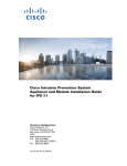
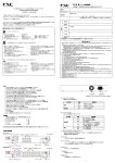
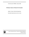
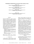
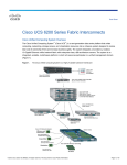
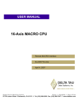
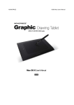
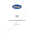
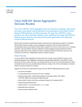
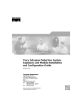
CH A P T E R
7
Installing the IPS 4510 and IPS 4520
Contents
This chapter describes the Cisco IPS 4510 and IPS 4520, and includes the following sections:
•
Installation Notes and Caveats, page 7-1
•
Product Overview, page 7-2
•
Chassis Features, page 7-3
•
Specifications, page 7-9
•
Accessories, page 7-10
•
Memory Configurations, page 7-11
•
Power Supply Module Requirements, page 7-11
•
Supported SFP/SFP+ Modules, page 7-11
•
Installing the IPS 4510 and IPS 4520, page 7-12
•
Removing and Installing the Core IPS SSP, page 7-15
•
Removing and Installing the Power Supply Module, page 7-17
•
Removing and Installing the Fan Module, page 7-19
•
Installing the Slide Rail Kit Hardware, page 7-20
•
Installing and Removing the Slide Rail Kit, page 7-21
•
Rack-Mounting the Chassis Using the Fixed Rack Mount, page 7-30
•
Installing the Cable Management Brackets, page 7-33
•
Troubleshooting Loose Connections, page 7-34
•
IPS 4500 Series Sensors and the SwitchApp, page 7-35
Installation Notes and Caveats
Pay attention to the following installation notes and caveats before installing the IPS 4510 and IPS 4520.
Note
Read through the entire guide before beginning any of the installation procedures.
Cisco Intrusion Prevention System Appliance and Module Installation Guide for IPS 7.1
OL-24002-01
7-1
Chapter 7
Installing the IPS 4510 and IPS 4520
Product Overview
Warning
Only trained and qualified personnel should install, replace, or service this equipment. Statement 49
Caution
Read the safety warnings in the Regulatory Compliance and Safety Information for the Cisco Intrusion
Prevention System 4500 Series Sensor Appliance document and follow proper safety procedures when
performing the steps in this guide.
Product Overview
The IPS 4510 delivers 3Gbps of intrusion prevention performance based on real world deployment
traffic patterns. You can use the IPS 4510 to protect multi-Gbps aggregated traffic traversing switches
from multiple subnets and for medium sized data centers. The IPS 4510 is a purpose-built device that
has support for both copper and fiber NIC environments thus providing flexibility of deployment in any
environment. Based on the ASA 5585-X chassis, the IPS 4510 provides a proven hardware environment
for stand-alone IPS protection. It ships with one power supply module, but optional redundant,
hot-swappable power supply modules are available as well as hot-swappable fan modules in case of
failures. All port numbers are numbered from right to left beginning with 0. This platform replaces the
IPS 4270-20.
The IPS 4520 delivers 5 Gbps of intrusion prevention performance. You can use the IPS 4520 to protect
multi-Gigabit networks and aggregated traffic traversing switches from multiple subnets. The IPS 4520
is a purpose-built device that has support for both copper and fiber NIC environments thus providing
flexibility of deployment in any environment. The IPS 4520 ships with two power supply modules, but
optional redundant, hot-swappable power supply modules are available as well as hot-swappable fan
modules in case of failures. All port numbers are numbered from right to left beginning with 0. It is also
based on the ASA 5585-X chassis.
Both the IPS 4510 and IPS 4520 have a console port, an auxiliary port, two 1 Gb (copper) management
ports, and a total of 10 data ports—6 GigabitEthernet copper ports and 4 SFP/SFP+ module (1 or 10 Gb)
ports.
Note
The management ports are Management 0/0 and Management 0/1. Management 0/1 is reserved for future
use.
Note
Online insertion and removal (OIR) of the SFP/SFP+ module, power supply module, and fan module is
supported.
Caution
If you remove a power supply or fan module, replace it immediately to prevent disruption of service.
IDM
The IPS 4510 and IPS 4520 support the Intrusion Prevention System Device Manager (IDM) 7.1.4 and
later. IDM delivers security management and monitoring through an intuitive, easy-to-use web-based
management interface. IDM is a Java Web Start application that enables you to configure and manage
your IPS 4510 and IPS 4520. IDM is bundled with IPS 7.1. You can access it through Internet Explorer
or Firefox web browsers.
Cisco Intrusion Prevention System Appliance and Module Installation Guide for IPS 7.1
7-2
OL-24002-01
Chapter 7
Installing the IPS 4510 and IPS 4520
Chassis Features
IME
The Intrusion Prevention System Manager Express (IME) 7.2.3 and later also support the IPS 4510 and
IPS 4520. IME is a network management application that provides system health, events, and
collaboration monitoring in addition to reporting and configuration for up to ten sensors. IME monitors
sensor health using customizable dashboards and provides security alerts through RSS feed integration
from the Cisco Security Intelligence Operations site. It monitors global correlation data, which you can
view in events and reports. It monitors events and lets you sort views by filtering, grouping, and
colorization. IME also supports tools such, as ping, trace route, DNS lookup, and whois lookup for
selected events. It contains a flexible reporting network. It embeds the IDM configuration component to
allow for a seamless integration between the monitoring and configuration of IPS devices. Within IME
you can set up your sensors, configure policies, monitor IPS events, and generate reports. IME works in
single application mode—the entire application is installed on one system and you manage everything
from that system.
Chassis Features
This section describes the IPS 4510 and IPS 4520 chassis features and indicators. Figure 7-1 shows the
grounding lug on the left side of the chassis (when facing the front of the chassis).
Figure 7-1
1
IIPS 4510 and IPS 4520 Side Chassis View
Grounding lug
Cisco Intrusion Prevention System Appliance and Module Installation Guide for IPS 7.1
OL-24002-01
7-3
Chapter 7
Installing the IPS 4510 and IPS 4520
Chassis Features
Figure 7-2 shows the front view of the IPS 4510 and IPS 4520.
Figure 7-2
IPS 4510 and IPS 4520 Front Panel Features
Cisco IPS 4520
1
9
1
3
8
7
6
4
5
6
SFP/SFP+
2
5
4
3
2
1
0
7
1
8
MGMT
0
9
USB
R
PW
OT
BO
M
AR
AL
T
AC
10 11
N
VP
1
PS
0
PS
D1
HD
D0
HD
12
RESET
AUX
CONSOLE
331672
Cisco ASA 5585-X IPS SSP
0
13 14 15 1
1
Removal screws
2
Reserved bays for hard disk drives1
3
TenGigabitEthernet 0/9
(1-Gb and 10-Gb fiber SFP/SFP+ modules)
4
TenGigabitEthernet 0/8
(1-Gb and 10-Gb fiber SFP/SFP+ modules)
5
TenGigabitEthernet 0/7
(1-Gb and 10-Gb fiber SFP/SFP+ modules)
6
TenGigabitEthernet 0/6
(1-Gb and 10-Gb fiber SFP/SFP+ modules)
7
GigabitEthernet 0/0 through 0/5
(from right to left, 1-Gb copper RJ45)
8
Management 0/12
(GigabitEthernet RJ45)
9
Management 0/0
(GigabitEthernet RJ45)
10
USB port
11 USB port
12
Front panel indicators
13 Auxiliary port (RJ45)
14
Console port (RJ45)
15 Reset3
1. Hard disk drives are not supported at this time. The hard disk drive bays are empty.
2. Reserved for future use.
3. Reserved for future use.
Cisco Intrusion Prevention System Appliance and Module Installation Guide for IPS 7.1
7-4
OL-24002-01
Chapter 7
Installing the IPS 4510 and IPS 4520
Chassis Features
Figure 7-3 shows the front panel indicators.
Figure 7-3
Front Panel Indicators
1
USB
R
PW
OT
BO
1
M
AR
AL
T
AC
3
N
VP
1
PS
5
2
4
0
PS
D1
HD
7
6
1 PWR
2
BOOT
3 ALARM
4
ACT1
5 VPN2
6
PS1
7 PS0
8
HDD13
D0
HD
AUX
CONSOLE
253904
0
9
8
9 HDD24
1. Not supported at this time.
2. Not supported at this time.
3. Not supported at this time.
4. Not supported at this time.
Table 7-1 describes the front panel indicators on the IPS 4510 and IPS 4520.
Table 7-1
Front Panel Indicators
Indicator
Description
PWR
Indicates whether the system is off or on:
BOOT
ALARM
•
Off—No power.
•
Green—System has power.
Indicates how the power-up diagnostics are proceeding:
•
Flashing green—Power-up diagnostics are running or the system is booting.
•
Green—System has passed power-up diagnostics.
•
Amber—Power-up diagnostics failed.
Indicates whether a component has failed:
•
Off—No alarm.
•
Flashing yellow—Critical alarm.
Major failure of hardware component or software module, temperature over
the limit, power out of tolerance, or OIR is ready to remove the module.1
ACT
Not supported at this time.
VPN
Not supported at this time.
Cisco Intrusion Prevention System Appliance and Module Installation Guide for IPS 7.1
OL-24002-01
7-5
Chapter 7
Installing the IPS 4510 and IPS 4520
Chassis Features
Table 7-1
Front Panel Indicators (continued)
Indicator
Description
PS1
Indicates the state of the power supply module installed on the right when facing
the back panel:
PS0
HDD1
HDD2
•
Off—No power supply module present or no AC input.
•
Green—Power supply module present, on, and good.
•
Amber—Power or fan module off or failed.
Indicates the state of the power module installed on the left when facing the back
panel:
2
3
•
Off—No power supply module present or no AC input.
•
Green—Power supply module present, on, and good.
•
Amber—Power or fan module off or failed.
Indicates activity on the hard disk drive:
•
Off—No hard disk drive present.
•
Flashing green—Hard disk drive activity.
•
Amber—Hard disk drive failure.
Indicates activity on the hard disk drive:
•
Off—No hard disk drive present.
•
Flashing green—Hard disk drive activity.
•
Amber—Hard disk drive failure.
1. OIR is not available at this time.
2. The hard disk drive bays are reserved for future use.
3. The hard disk drive bays are reserved for future use.
Cisco Intrusion Prevention System Appliance and Module Installation Guide for IPS 7.1
7-6
OL-24002-01
Chapter 7
Installing the IPS 4510 and IPS 4520
Chassis Features
Figure 7-4 shows the back panel features.
Figure 7-4
Back Panel Features
3
1
2
7
4
6
Cisco-ASA-FAN
O
FA UT
IL
F
O AN
K
100-240V
15.0/8.0.A
56/60Hz
I
ON
K
Cisco ASA 1200W AC
2
5
8
1
Power supply module (corresponds to
PS1 indicator)
2
Power supply module/fan module removal
screws
3
Power supply module plug
4
Toggle On/Off switch for power supply module
5
Power supply module indicators
6
Power supply module or fan module handle
7
Fan module
8
Fan module indicator
Figure 7-5 shows the power supply module indicators.
Figure 7-5
Power Supply Module Indicators
1 IN OK
2
O
FA UT
IL
1
2
3
253905
F
O AN
K
100-240V
15.0/8.0.A
56/60Hz
I
ON
K
Cisco ASA 1200W AC
FAN OK
3 OUT FAIL
Cisco Intrusion Prevention System Appliance and Module Installation Guide for IPS 7.1
OL-24002-01
7-7
Chapter 7
Installing the IPS 4510 and IPS 4520
Chassis Features
Table 7-2 describes the power supply module and fan module indicators.
Table 7-2
Power Supply Module and Fan Module Indicators
Indicator
Description
IN OK
Indicates status of power supply module:
FAN OK
•
Off—No AC power cord connected or AC
power switch off.
•
Green—AC power cord connected and AC
power switch on.
Indicates status of fan module
OUT FAIL
•
Off—Fan module failure or AC power switch
off.
•
Green—AC power cord connected, AC power
switch on, and internal fan is running.
•
Red—Output voltage failure1
1. The power supply module has three output voltages—3.3V, 12V, and 50V.
Table 7-3 describes the Ethernet port indicators.
Table 7-3
Ethernet Port Indicators
Indicator
Gigabit Ethernet (RJ45)
Description
•
Left side:
– Green—Physical activity
– Flashing green—Network activity
•
Right side:
– Not lit—10 Mbps
– Green—100 Mbps
– Amber—1000 Mbps
Cisco Intrusion Prevention System Appliance and Module Installation Guide for IPS 7.1
7-8
OL-24002-01
Chapter 7
Installing the IPS 4510 and IPS 4520
Specifications
Table 7-3
Ethernet Port Indicators (continued)
Indicator
Description
10-Gigabit Ethernet Fiber
(SFP+)/1-Gigabit Ethernet Fiber
(SFP)
•
Left side:
– Off—No 10-Gigabit Ethernet physical link
– Green—10-Gigabit Ethernet physical link
– Flashing green1—Network activity
•
Right side:
– Off—No 1-Gigabit Ethernet physical link
– Green—1-Gigabit Ethernet physical link
– Flashing green1—Network activity
Management port
•
Left side:
– Green—Physical activity
– Flashing green—Network activity
•
Right side:
– Not lit—10 Mbps
– Green—100 Mbps
– Amber—1000 Mbps
1. Flashing is in proportion to the percentage of number of packets or bytes received.
Specifications
Table 7-4 lists the specifications for the IPS 4510 and IPS 4520.
Table 7-4
IPS 4510 and IPS 4520 Specifications
Dimensions and Weight
Height
3.47 in (8.8 cm)
Width
19 in (48.3 cm)
Depth
26.5 in (67.3 cm)
Weight
50 lb (22.7 kg)
Form factor
2 RU, standard 19-inch rack-mountable
Power
Rated input voltage
(per power supply module)
100 to 127 VAC
200 to 240 VAC
Rated input frequency
50 to 60 Hz
Rated input power
1465W @ 100 VAC
1465W @ 200 VAC
Rated input current
12A (100 VAC)
8A (200 VAC)
Cisco Intrusion Prevention System Appliance and Module Installation Guide for IPS 7.1
OL-24002-01
7-9
Chapter 7
Installing the IPS 4510 and IPS 4520
Accessories
Table 7-4
IPS 4510 and IPS 4520 Specifications (continued)
Maximum heat dissipation
3960 BTU/hr (100 VAC)
5450 BTU/hr (200 VAC)
Power supply output steady state 1200W
Maximum peak
1200W
Environment
Temperature
Operating 32°F to 104°F (0°C to 40°C)
Nonoperating -40°F to 158°F (-40°C to 70°C)
Airflow
Front to back
Relative humidity
(noncondensing)
Operating 10% to 90%
Nonoperating 5% to 95%
Altitude
Operating 0 to 3000 ft (9843 ft)
Nonoperating 0 to 4570 ft (15,000 ft)
Shock
Operating Half-sine 2 G, 11 ms pulse, 100 pulses
Nonoperating 15 G, 170 in/sec delta V
Vibration
2.2 Grms, 10 minutes per axis on all three axes
Noise
65 dBa max
Accessories
The contents of the sensor packing box contains the following items you need to install the sensor:
•
Sensor chassis
•
Documentation
•
2 Yellow Ethernet cables
•
Blue console cable PC terminal adapter
•
Power cable 120V
Note
The IPS 4510 ships with one power supply module installed and one power cable. The IPS
4520, ships with two power supply modules installed and two power cables.
•
Screws
•
Cable management brackets
•
Front and rear rack-mount brackets
•
Slide rail kit hardware
•
Slide rail kit
Cisco Intrusion Prevention System Appliance and Module Installation Guide for IPS 7.1
7-10
OL-24002-01
Chapter 7
Installing the IPS 4510 and IPS 4520
Memory Configurations
Memory Configurations
The IPS 4510 and IPS 4520 have up to 6 DIMM modules per CPU. DIMM population is
platform-dependent. Table 7-5 shows the memory configurations.
Table 7-5
Memory Configurations
Model
Memory
IPS 4510
24-GB DRAM
IPS 4520
48-GB DRAM
Power Supply Module Requirements
Table 7-6 lists the power supply module requirements.
Table 7-6
Power Supply Module Requirements
50 V
12 V
3.3 V_STBY
Maximum
52.0 V
12.2. V
3.45 V
Nominal
50.0 V
12.0 V
3.35 V
Minimum
48.0 V
11.8 V
3.25 V
Maximum
17.3 A
27.0 A
1.5 A
Minimum
0
0
0
Maximum
17.3 A
27.0 A
1.5 A
Minimum
0
0
0
Output Voltage
Output Current @ 200 VAC
Output Current @ 100 VAC
Note
The IPS 4520 requires two power supply modules.
Supported SFP/SFP+ Modules
The SFP/SFP+ module is a hot-swappable input/output device that plugs into the SFP/SFP+ ports and
provides Gigabit Ethernet connectivity. The SFP and SFP+ modules are optional and not included with
the IPS 4510 and IPS 4520. You can purchase them separately. For 1 Gb, you need SFP. For 10Gb, you
need SFP+. The interfaces are called TenGigabitEthernet 0/x whether they are 10 Gb-enabled or not.
Cisco Intrusion Prevention System Appliance and Module Installation Guide for IPS 7.1
OL-24002-01
7-11
Chapter 7
Installing the IPS 4510 and IPS 4520
Installing the IPS 4510 and IPS 4520
Table 7-7 lists the SFP/SFP+ modules that the IPS 4510 and IPS 4520 support.
Table 7-7
SFP/SFP+ Modules
1G SFP Module
GLC-SX-MM
1000 Base-SX SFP module
GLC-SX-MMD
1000BASE-SX short wavelength, with DOM
GLC-LH-SM
1000 Base-LX/LH SFP module
GLC-LH-SMD
1000BASE-LX/LH long-wavelength, with DOM
GLC-T
1000BASE-T standard
10G SFP+ Module
SFP-10G-ER
10G ER SFP+ module
SFP-10G-SR
10G SR SFP+ module
SFP-10G-LRM
10G LRM SFP+ module
SFP-10G-LR
10G LR SFP+ module
SFP-H10GB-ACU7M
10GBASE-CU SFP+ Cable 7 Meter, active
SFP-H10GB-ACU10M
10GBASE-CU SFP+ Cable 10 Meter, active
SFP-H10GB-CU1M
10GBASE-CU SFP+ cable 1 meter, passive
SFP-H10GB-CU3M
10GBASE-CU SFP+ cable 3 meter, passive
SFP-H10GB-CU5M
10GBASE-CU SFP+ cable 5 meter, passive
Installing the IPS 4510 and IPS 4520
The IPS 4510 and IPS 4520 have two dedicated Gigabit Ethernet interfaces for device management that
are called Management 0/0 and Management 0/1. The additional interface, Management 0/1 is reserved
for future use. The management interfaces are similar to the console port, because they only accept
traffic that is destined to-the-box (versus traffic that is through-the-box).
To connect the IPS 4510 and IPS 4520 cables to the network interfaces, follow these steps:
Step 1
Place the sensor on a flat, stable surface, or in a rack (if you are rack-mounting it).
Step 2
Connect to the management interface, Management 0/0.
a.
Locate an Ethernet cable, which has an RJ-45 connector on each end.
Cisco Intrusion Prevention System Appliance and Module Installation Guide for IPS 7.1
7-12
OL-24002-01
Chapter 7
Installing the IPS 4510 and IPS 4520
Installing the IPS 4510 and IPS 4520
Connect one RJ-45 connector to the Management 0/0 interface.
7
6
5
4
3
2
1
0
0
1
MGMT
0
1
USB
c.
253908
b.
Connect the other end of the Ethernet cable to the Ethernet port on your computer or to your
management network.
Caution
Management and console ports are privileged administrative ports. Connecting them to an untrusted
network can create security concerns.
Step 3
(Optional) Connect to the sensor console port if you want to use the IPS CLI. Use the console port to
connect to a computer to enter configuration commands.
Before connecting a computer or terminal to any ports, determine the baud rate of the serial port.
The baud rate of the computer or terminal must match the default baud rate (9600 baud) of the
console port of the adaptive security appliance. Set up the terminal as follows: 9600 baud (default), 8
data bits, no parity, 1 stop bits, and Flow Control (FC) = Hardware.
b.
Connect the RJ-45 to the console port and connect the other end to your computer.
(Optional) Connect to the SFP/SFP+ port if you are using fiber ports. The IPS 4510 and the IPS 4520
have four SFP/SFP+ ports. If you are using the fiber ports, you need an SFP+ module for 10-Gigabit
Ethernet or an SFP module for 1-Gigabit Ethernet (SFP or SFP+ modules are not included).
9
8
7
6
SFP/SFP
+
a.
253906
Step 4
a.
Install the SFP/SFP+ module.
Cisco Intrusion Prevention System Appliance and Module Installation Guide for IPS 7.1
OL-24002-01
7-13
Chapter 7
Installing the IPS 4510 and IPS 4520
Installing the IPS 4510 and IPS 4520
Connect one end of the LC cable to the SFP/SFP+ module.
9
8
7
6
253907
b.
SFP/SFP
+
c.
Step 5
Connect the other end of the LC cable to a network device, such as a router or switch.
Install the electrical cables.
a.
Attach the power cable to the power supply module on the back of the sensor.
Cisco AS
A 1200W
AC
Cisco-A
SA
Cisco AS -FAN
A 1200W
AC
IN K FAN
UT
O
OK O AIL
253972
100-240
V
15.0/8.0
.A
56/60Hz
INP
F
UT FAN
OUTPUT
100-240
V
15.0/8.0
.A
56/60Hz
If you have redundant power supply modules, you must connect both power cables to the back of
the sensor.
2
2
1
Power supply module (PS0)
c.
Plug the power cable(s) in to a power source (we recommend a UPS).
Cisco ASA 1200W AC
100-240V
15.0/8.0.A
56/60Hz
O
FA UT
IL
O
FA UT
IL
F
O AN
K
100-240V
15.0/8.0.A
56/60Hz
I
ON
K
Cisco ASA 1200W AC
F
O AN
K
1
I
ON
K
b.
IN K FAN
UT
O
OK O FAIL
Power supply module (PS1)
Cisco Intrusion Prevention System Appliance and Module Installation Guide for IPS 7.1
7-14
OL-24002-01
Chapter 7
Installing the IPS 4510 and IPS 4520
Removing and Installing the Core IPS SSP
Step 6
Power on the sensor.
Caution
If the appliance is subjected to environmental overheating, it shuts down and you must manually power
cycle it to turn it on again.
Step 7
Check the PWR indicator on the front panel of the sensor to verify power socket connectivity. It should
be green. To verify power supply operation, check the PS0 and PS1 indicators on the front panel. They
should be green. On the back panel of the sensor, make sure the IN OK and the FAN OK indicators are
green and the OUT FAIL indicator is off.
For More Information
For a list of the supported SFP/SFP+ modules, see Supported SFP/SFP+ Modules, page 7-11.
Removing and Installing the Core IPS SSP
You can uninstall the core IPS SSP in the IPS 4510 and IPS 4520, for example, if you need to move it to
a different chassis or replace it.
To remove and install the core IPS SSP in the IPS 4510 and IPS 4520, follow these steps:
Step 1
Log in to the CLI.
Step 2
Prepare the sensor to be powered off. Wait for the power down message before continuing with Step 3.
sensor# reset powerdown
Note
You can also power off the sensor using the IDM or the IME.
Step 3
Press Enter to confirm.
Step 4
Power off the sensor.
Step 5
Remove the power cable from the sensor.
Step 6
From the front panel of the sensor, loosen the captive screws from the bottom slot.
Cisco Intrusion Prevention System Appliance and Module Installation Guide for IPS 7.1
OL-24002-01
7-15
Chapter 7
Installing the IPS 4510 and IPS 4520
Removing and Installing the Core IPS SSP
Step 7
Grasp the ejection levers at the left and right bottom of the designated slot and pull them out.
SFP31
SFP20
SFP17
SFP60
5
4
3
2
4520
331818
Cisco IPS
1
0
0
1
MGMT
0
USB
1
R
PW
2
OT
BO
M
AR
AL
T
AC
N
VP
1
PS
0
PS
D1
HD
D0
HD
AUX
CONSOL
E
RESET
1
2
1
2
Module
Ejection levers
Step 8
Grasp the sides of the module and pull it all the way out of the chassis.
Step 9
Install the new module by lining it up with the module slot making sure the ejection levers are extended.
SFP31
SFP20
SFP17
SFP60
5
4
3
2
4520
331818
Cisco IPS
1
0
0
1
MGMT
0
USB
1
2
R
PW
BO
OT
M
AR
AL
T
AC
N
VP
1
PS
0
PS
D1
HD
D0
HD
AUX
CONSOL
E
RESET
1
2
1
Module
2
Ejection levers
Step 10
Slide the module into the slot until it is seated and push the ejection levers back into place.
Step 11
Tighten the screws.
Step 12
Reconnect the power cable to the sensor.
Step 13
Power on the sensor.
Step 14
Verify that the PWR indicator on the front panel is green.
Cisco Intrusion Prevention System Appliance and Module Installation Guide for IPS 7.1
7-16
OL-24002-01
Chapter 7
Installing the IPS 4510 and IPS 4520
Removing and Installing the Power Supply Module
Removing and Installing the Power Supply Module
The IPS 4510 ships with one power supply module and one fan module installed, and the IPS 4520 ships
with two power supply modules installed in a load balancing/sharing configuration. This configuration
ensures that if one power supply module fails, the other power supply module assumes the full load until
the failed power supply module is replaced. To maintain airflow, both bays must be populated by either
a power supply module and a fan module or two power supply modules.
You can replace the fan module with a second power supply module in the IPS 4520 to create a redundant
power supply module configuration. If you already have two power supply modules installed, you can
install or replace either power supply module without powering off the sensor, as long as one power
supply module is active and functioning correctly.
If only one power supply module is installed, do not remove the power supply module unless the sensor
has been powered off. Removing the only operational power supply module causes an immediate power
loss.
Caution
If you remove a power supply or fan module, replace it immediately to prevent disruption of service.
Caution
If the appliance is subjected to environmental overheating, it shuts down and you must manually power
cycle it to turn it on again.
To remove and install the power supply module, follow these steps:
Step 1
If you are removing the only power supply module, power off the sensor.
Step 2
From the back panel of the sensor, unplug the power supply module cable.
Step 3
On the back of the sensor, loosen the captive screws from the power supply module.
2
Cisco AS
A 1200W
AC
Cisco-A
SA
100-240V
15.0/8.0.
A
56/60Hz
253970
Cisco AS -FAN
A 1200W
AC
IN K FAN
UT
O
OK O FAIL
100-240V
15.0/8.0.
A
56/60Hz
1
IN K FAN
UT
O
OK O FAIL
2
1
Step 4
Power supply module and power
supply module handle
2
Power supply module screws
Remove the power supply module by grasping the handle and pulling the power supply module away
from the chassis.
Cisco Intrusion Prevention System Appliance and Module Installation Guide for IPS 7.1
OL-24002-01
7-17
Chapter 7
Installing the IPS 4510 and IPS 4520
Removing and Installing the Power Supply Module
Step 5
Install the new power supply module by aligning it with the power supply module bay and pushing it
into place until it is seated.
2
Cisco AS
A
1200W
AC
Cisco-A
SA
253971
Cisco AS -FAN
A 1200W
AC
100-240V
IN K
15.0/8.0.
A
O
56/60Hz
INP
N
FA K OUT IL
O
FA
UT FAN
OUTPUT
100-240V
15.0/8.0.
A
56/60Hz
1
IN K FAN
UT
O
OK O FAIL
2
2
Power supply module and power
supply module handle
Power supply module screws
Step 6
Tighten the captive screws.
Step 7
Reconnect the power cable. If you are installing two power supply modules for a redundant
configuration, plug each one into a power source (we recommend a UPS).
2
1
Power supply module (PS0)
2
Cisco ASA 1200W AC
100-240V
15.0/8.0.A
56/60Hz
O
FA UT
IL
O
FA UT
IL
F
O AN
K
100-240V
15.0/8.0.A
56/60Hz
I
ON
K
Cisco ASA 1200W AC
F
O AN
K
1
I
ON
K
1
Power supply module (PS1)
Step 8
If you had to power off the sensor because you are removing and replacing the only power supply
module, power it back on.
Step 9
Check the PS0 and PS1 indicators on the front panel to make sure they are green. On the back panel of
the sensor, make sure the IN OK and the FAN OK indicators are green and the OUT FAIL indicator is off.
Cisco Intrusion Prevention System Appliance and Module Installation Guide for IPS 7.1
7-18
OL-24002-01
Chapter 7
Installing the IPS 4510 and IPS 4520
Removing and Installing the Fan Module
Removing and Installing the Fan Module
The IPS 4510 ships with one power supply module and one fan module installed, and the IPS 4520 ships
with two power supply modules instead of a power supply module and a fan module. You can replace
the fan module in the IPS 4510 if necessary. The fan module is hot-pluggable. You can install or replace
the fan module without powering down the sensor, as long as the power supply module is active and
functioning correctly. To maintain airflow, both bays must be populated by either a power supply module
and a fan module or two power supply modules.
Note
Caution
A power supply module is required for the system to operate.
If you remove a power supply or fan module, replace it immediately to prevent disruption of service.
To remove and install the fan module, follow these steps:
Step 1
From the right-hand side of the back panel of the sensor loosen the fan module screws until they release.
The screws are captive in the front panel.
2
Cisco AS
A
1200W
AC
Cisco-A
SA-FA
IN K FAN
UT
O
OK O FAIL
253909
100-240
V
15.0/8.0
.A
56/60Hz
N
3
1
2
Step 2
1
Fan module and fan module handle
3
Power supply module
2
Fan module screws
Remove the fan module by grasping the handle and pulling the fan module away from the chassis.
Cisco Intrusion Prevention System Appliance and Module Installation Guide for IPS 7.1
OL-24002-01
7-19
Chapter 7
Installing the IPS 4510 and IPS 4520
Installing the Slide Rail Kit Hardware
Step 3
Install the new fan module by aligning it with the fan module bay and pushing it into place until it is
seated.
2
Cisco AS
A
1200W
AC
Ci
Cisc
sco-A
o-ASA
SA-FA
-FANN
100-240
V
15.0/8.0
.A
56/60Hz
253910
IN K FAN
UT
O
OK O FAIL
3
1
2
1
Fan module and fan handle
3
Power supply module
2
Fan module screw
Step 4
Tighten the captive screws.
Step 5
Verify that the fan indicator on the lower right-hand of the back panel is green.
Installing the Slide Rail Kit Hardware
Before installing the appliance in the slide rail kit, you must install the slide rail kit hardware.
To install the slide rail kit hardware on the IPS 4510 and IPS 4520, follow these steps:
Step 1
Power off the appliance.
Step 2
Remove the power cable from the appliance.
Step 3
If your appliance has the fixed cable management brackets, do the following:
a.
Remove the cable management brackets from the front sides of the appliance.
b.
Remove the appliance from the rack.
c.
Remove the front brackets, left and right side brackets, and left and right rear brackets from the
appliance.
Cisco Intrusion Prevention System Appliance and Module Installation Guide for IPS 7.1
7-20
OL-24002-01
Chapter 7
Installing the IPS 4510 and IPS 4520
Installing and Removing the Slide Rail Kit
Figure 7-6 shows all of the brackets that can be removed for the fixed rack mount.
Brackets for the Fixed Rack Mount
SFP1
SFP0
7
6
5
4
3
2
1
0
0
1
MGMT
0
USB
SFP1
344202
Figure 7-6
1
R
PW
M
OT
AR
BO
T
AL
AC
N
VP
PS
1
7
6
0
PS
SFP0
D1
HD
D0
HD
AUX
5
4
3
2
1
0
1
MGMT
0
USB
RESET
CONSOLE
RESET
1
R
PW
M
OT
AR
BO
T
AL
AC
N
VP
PS
1
0
PS
D1
HD
D0
HD
AUX
Step 4
CONSOLE
0
Attach the slide rail kit hardware (front brackets and left and right side brackets) to the appliance. The
brackets are labelled RIGHT and LEFT. This prepares the appliance for installation in the rack using the
slide rail kit. Figure 7-7 shows all of the brackets you need to install on the appliance.
Brackets for the Slide Rail Kit
333331
Figure 7-7
Installing and Removing the Slide Rail Kit
After you have installed the slide rail kit hardware, you can install the slide rail kit. This section
describes how to install and remove the slide rail kit for the IPS 4510 and IPS 4520, and contains the
following sections:
•
Package Contents, page 7-22
•
Installing the Chassis in the Rack, page 7-22
•
Removing the Chassis from the Rack, page 7-28
Cisco Intrusion Prevention System Appliance and Module Installation Guide for IPS 7.1
OL-24002-01
7-21
Chapter 7
Installing the IPS 4510 and IPS 4520
Installing and Removing the Slide Rail Kit
Package Contents
The slide rail kit package contains the following items:
•
Left and right slide rails
•
Six #10-32 screws
•
Two #10-32 cage nuts
Installing the Chassis in the Rack
To install the chassis in the rack using the slide rail kit, follow these steps:
Step 1
Press the latch on the end of the slide rail and push forward to engage the pins in the rack until the clip
clicks and locks around the rack post (Figure 7-8).
Note
The slide rails are labeled ‘left’ and ‘right.’ Install the left slide rail on the left side of the rack
and the right slide rail on the right side of the rack.
Press and Push to Install the Slide Rail
330560
Figure 7-8
Cisco Intrusion Prevention System Appliance and Module Installation Guide for IPS 7.1
7-22
OL-24002-01
Chapter 7
Installing the IPS 4510 and IPS 4520
Installing and Removing the Slide Rail Kit
For square hole posts, square studs must be attached fully inside the square hole on the rack rail. For
threaded hole posts, the round stud must fully enter inside the threaded hole rack rail (Figure 7-9).
Note
After installing the square or round studs into the rack post, verify that the locking clip is fully
seated and secure against the rack rail.
Square Studs for Square Hole Post
330561
Figure 7-9
Cisco Intrusion Prevention System Appliance and Module Installation Guide for IPS 7.1
OL-24002-01
7-23
Chapter 7
Installing the IPS 4510 and IPS 4520
Installing and Removing the Slide Rail Kit
Step 2
Caution
Secure the slide rail to the rack post with the provided #10-32 screws by tightening the screws at the front
and rear end of the slide rail to the rack post (Figure 7-10). Both front and rear rack posts must be secured
with the screws before you install the chassis.
It is critical that the screws are installed and secured to the front and rear end of the slide rails.
Securing the Slide Rail to the Rack Post
332655
Figure 7-10
Cisco Intrusion Prevention System Appliance and Module Installation Guide for IPS 7.1
7-24
OL-24002-01
Chapter 7
Installing the IPS 4510 and IPS 4520
Installing and Removing the Slide Rail Kit
Step 3
For square hole racks, install one #10-32 cage nut on each side of the rack rail (Figure 7-11). Leave one
square hole spacing above the slide rail. The cage nut will be used later to secure the chassis to the rack
post. For threaded hole racks, no additional hardware is needed.
Installing the #10-32 Cage Nuts
332656
Figure 7-11
Cisco Intrusion Prevention System Appliance and Module Installation Guide for IPS 7.1
OL-24002-01
7-25
Chapter 7
Installing the IPS 4510 and IPS 4520
Installing and Removing the Slide Rail Kit
Step 4
Install the chassis on the outer rail. Make sure that the U-bars are aligned to the outer rail evenly, then
push the chassis into the rack (Figure 7-12).
Caution
Before installing the chassis, make sure that the slide rails are properly installed and that the perforated
holes on the outer slide rail align with the perforated holes on the chassis.
330562
Figure 7-12 Installing the Chassis on the Outer Rail
Cisco Intrusion Prevention System Appliance and Module Installation Guide for IPS 7.1
7-26
OL-24002-01
Chapter 7
Installing the IPS 4510 and IPS 4520
Installing and Removing the Slide Rail Kit
Step 5
Tighten the screws to secure the chassis to the rack (Figure 7-13). Use the upper hole to secure the
chassis to the rack.
a.
For square hole racks, secure the chassis to the rack by installing the #10-32 screw into the cage nut
that you installed in Step 3.
b.
For threaded hole racks, secure the front of the chassis by installing the #10-32 screws into the rack
threaded hole.
330563
Figure 7-13 Securing the Chassis to the Outer Rail
Cisco Intrusion Prevention System Appliance and Module Installation Guide for IPS 7.1
OL-24002-01
7-27
Chapter 7
Installing the IPS 4510 and IPS 4520
Installing and Removing the Slide Rail Kit
Removing the Chassis from the Rack
To remove the chassis from the rack, follow these steps:
Step 1
Remove the screws from the front brackets of the rail post (Figure 7-14).
Removing the Screws from the Outer Rail
330599
Figure 7-14
Step 2
Pull out the chassis to the locked position.
Cisco Intrusion Prevention System Appliance and Module Installation Guide for IPS 7.1
7-28
OL-24002-01
Chapter 7
Installing the IPS 4510 and IPS 4520
Installing and Removing the Slide Rail Kit
Step 3
Press down the release hook to remove the chassis from the rack (Figure 7-15).
Pressing Down the Release Hook
330564
Figure 7-15
Cisco Intrusion Prevention System Appliance and Module Installation Guide for IPS 7.1
OL-24002-01
7-29
Chapter 7
Installing the IPS 4510 and IPS 4520
Rack-Mounting the Chassis Using the Fixed Rack Mount
Step 4
Remove the two screws from the front and rear of the rack that are securing the slide rail, and release the
latch and pull out the rails (Figure 7-16).
Releasing the Latch to Pull Out the Rails
330565
Figure 7-16
Rack-Mounting the Chassis Using the Fixed Rack Mount
If you are not able to use the slide rail kit in your rack installation, an optional fixed rack mount solution
is available. You can install fixed front and rear rack mount brackets on the ASA 5585-X so that you can
easily mount it in a rack.
The IPS 4510 and the IPS 4520 ship with front rack mount brackets so that you can easily mount them
in a rack.
To install the rack mount brackets on the sensor, follow these steps:
Step 1
If the sensor is already operational and not rack-mounted, or if you are replacing one sensor with another
sensor, do the following:
•
Power off the sensor.
•
Remove the power cable from the sensor.
•
Remove the old sensor from the rack.
Cisco Intrusion Prevention System Appliance and Module Installation Guide for IPS 7.1
7-30
OL-24002-01
Chapter 7
Installing the IPS 4510 and IPS 4520
Rack-Mounting the Chassis Using the Fixed Rack Mount
Position the front bracket on the side of the sensor and line up the bracket screws with the screw holes
on the sensor.
Cisco IPS
SFP1
SFP3
SFP0
SFP2
SFP17
6
SFP0
55
44
33
22
11
4510
00
00
11
MGM
MGMTT
00
USB
USB
11
RR
PW
PW
OTT
RRMM
BBOOO ALA
TT
ALA AC
AC
NN
VP
VP
11
PS
PS
00
PS
PS
D11
HHDDD
D00
HHDDD
AUX
AUX
CON
CONSOLE
SOLE
RESE
RESETT
1
1
2
Bracket
2
Bracket screws
Step 3
Tighten the screws in to the chassis.
Step 4
Repeat the procedure on the other side of the chassis.
Step 5
Mount the chassis in a rack. Go to Step 12. If using the optional slide rails, go to Step 6.
Step 6
(Optional) Attach one of the rear brackets using three M4 screws.
Cisco IPS
SFP1
2
2
4510
331821
Step 2
SFP0
7
6
5
4
3
2
1
0
0
1
MGMT
0
USB
1
R
PW
M
OT
AR
BO
T
AL
AC
N
VP
PS
1
0
PS
D1
HD
D0
HD
AUX
CONSOLE
RESET
Step 7
(Optional) Repeat the procedure to attach the second bracket to the other side of the chassis.
Step 8
(Optional) Measure the distance between the front and rear rack rails and select the proper slide-mount
brackets.
Note
The slide-mount brackets let you install the rear of the chassis to the rear rack rails. The brackets
are designed to slide within the installed rear brackets and accommodate a range of rack depths.
Cisco Intrusion Prevention System Appliance and Module Installation Guide for IPS 7.1
OL-24002-01
7-31
Chapter 7
Installing the IPS 4510 and IPS 4520
Rack-Mounting the Chassis Using the Fixed Rack Mount
(Optional) Install the proper slide-mount brackets on to the rear bracket on the chassis.
331822
Step 9
Cisco IPS
SFP1
SFP3
Step 10
SFP0
SFP2
SFP17
SFP06
55
44
33
22
11
00
4510
00
11
MGMT
MGMT
00
USB
USB
11
R
PWR
PW
M
OT
ARM T
BOOT ALAR
BO
AL
ACT
AC
N
VPN
VP
1
PS1
PS
0
PS0
PS
D1
HDD1
HD
D0
HDD0
HD
AUX
AUX
CONSOLE
CONS
OLE
RESE
RESETT
(Optional) For added security, screw in the front brackets to the rack.
4510
331823
Cisco IPS
Step 11
(Optional) Secure the slide brackets to the corresponding holes in the rear rack rail using the screws
provided.
RESET
RESET
Cisco ASA
1200W
AC
Cisco ASA
1200W
AC
N
T
IN
OK FAOK OU IL
FA
100-240V
15.0/8.0.
A
56/60Hz
Step 12
Reattach the power cable to the sensor.
Step 13
Power on the sensor.
N
T
IN
OK FAOK OU IL
FA
330149
100-240V
15.0/8.0.
A
56/60Hz
Cisco Intrusion Prevention System Appliance and Module Installation Guide for IPS 7.1
7-32
OL-24002-01
Chapter 7
Installing the IPS 4510 and IPS 4520
Installing the Cable Management Brackets
Installing the Cable Management Brackets
The IPS 4510 and IPS 4520 ship with two cable management brackets that you can use to organize the
cables connected to the sensor.
To install the cable management brackets on the sensor, follow these steps:
Step 1
Power off the sensor.
Step 2
Remove the power cable from the sensor.
Step 3
Position the cable management brackets on the front side of the sensor, and line up the bracket screws
with the screw holes on the sensor. Figure 7-17 shows the cable management bracket for the fixed rack
mount and Figure 7-18 on page 7-34 shows the cable management bracket for the slide rail.
Figure 7-17
Cable Management Brackets for the Fixed Rack Mount
SFP2
SFP2
SFP1
SFP1
SFP0
SFP0
55
44
33
22
11
00
4510
331824
Cisco IPS
SFP3
SFP3
00
11
MGM
MGMTT
00
USB
USB
11
R
PWPWR BOOTOT ARMM
BO ALALAR ACT T N
AC VPVPN PS1 1
0
PS PSPS0 HDD1D1 D0
HD HDHDD0
AUX
AUX
CONS
OLE
CONS
OLE
RESE
TT
RESE
Cisco Intrusion Prevention System Appliance and Module Installation Guide for IPS 7.1
OL-24002-01
7-33
Chapter 7
Installing the IPS 4510 and IPS 4520
Troubleshooting Loose Connections
Cable Management Brackets for the Slide Rail
333053
Figure 7-18
Step 4
Tighten the screws in to the rack.
Step 5
Reattach the power cable to the sensor.
Step 6
Organize the cables through the cable management brackets on the sensor.
Step 7
Power on the sensor.
Troubleshooting Loose Connections
Perform the following actions to troubleshoot loose connections on sensors:
•
Make sure all power cords are securely connected.
•
Make sure all cables are properly aligned and securely connected for all external and internal
components.
•
Remove and check all data and power cables for damage. Make sure no cables have bent pins or
damaged connectors.
•
Make sure each device is properly seated.
•
If a device has latches, make sure they are completely closed and locked.
•
Check any interlock or interconnect indicators that indicate a component is not connected properly.
•
If problems continue, remove and reinstall each device, checking the connectors and sockets for bent
pins or other damage.
Cisco Intrusion Prevention System Appliance and Module Installation Guide for IPS 7.1
7-34
OL-24002-01
Chapter 7
Installing the IPS 4510 and IPS 4520
IPS 4500 Series Sensors and the SwitchApp
IPS 4500 Series Sensors and the SwitchApp
The 4500 series sensors have a built in switch that provides the external monitoring interfaces of the
sensor. The SwitchApp is part of the IPS 4500 series design that enables the InterfaceApp and sensor
initialization scripts to communicate and control the switch. Any application that needs to get or set
information on the switch must communicate with the SwitchApp. Additionally the SwitchApp
implements the following:
•
Detects bypass—When the SensorApp is not monitoring, the SwitchApp places the switch in bypass
mode and then back to inspection mode once the SensorApp is up and running normally.
•
Collects port statistics—The SwitchApp monitors the switch and collects statistics on the external
interfaces of the switch for reporting by InterfaceApp.
•
Handles the external interface configuration—When you update the interface configuration, the
configuration is sent to the InterfaceApp, which updates the interface configuration for SwitchApp,
which then forwards that configuration on to the switch.
For More Information
For detailed information about the IPS system architecture, refer to System Architecture.
Cisco Intrusion Prevention System Appliance and Module Installation Guide for IPS 7.1
OL-24002-01
7-35
Chapter 7
Installing the IPS 4510 and IPS 4520
IPS 4500 Series Sensors and the SwitchApp
Cisco Intrusion Prevention System Appliance and Module Installation Guide for IPS 7.1
7-36
OL-24002-01